Article

Fiber Model Considering the Local Instability Effect and Its Application to the Seismic Analysis of Eccentrically Compressed Steel Piers

1
College of Civil Engineering and Architecture, Zhejiang University of Science &Technology, Hangzhou 310023, China
2
Center for Balance Architecture, Zhejiang University, Hangzhou 310058, China
3
College of Civil Science and Engineering, Yangzhou University, Yangzhou 225009, China
*
Author to whom correspondence should be addressed.
Appl. Sci. 2022, 12(12), 5838; https://doi.org/10.3390/app12125838
Submission received: 18 May 2022 / Revised: 3 June 2022 / Accepted: 6 June 2022 / Published: 8 June 2022
(This article belongs to the Special Issue Seismic Performance Assessment for Structures)

Abstract

:
To propose a seismic response calculation model for eccentrically compressed steel piers that can consider the local instability effect and horizontal bidirectional earthquake actions, in-plane and out-of-plane pseudo-static numerical simulation and bidirectional seismic response analysis are performed to study the applicability of the improved fiber model. The comparison results with the refined hybrid-element model show that the improved fiber model can accurately simulate the hysteretic performance of eccentrically compressed steel piers in the in-plane or out-of-plane directions and can be used to calculate the structural seismic requirements under the bidirectional action of rarely met earthquakes.

1. Introduction

Steel bridges have many advantages, such as high strength, light weight, good ductility, and convenient construction. This kind of structure is also environmentally friendly, that is, it is in line with the sustainable development goals. Since the Kobe Earthquake occurred in Japan in 1995, the seismic performance of single-column centrally compressed steel piers has been valued by experts and scholars worldwide. Through post-earthquake investigations [1,2] and structural test studies through pseudo-static loading [3,4,5,6,7] or pseudo-dynamic loading [8,9], it has been confirmed that the local instability of steel plates primarily causes the seismic damage of steel piers. To determine the seismic performance of single-column centrally compressed steel piers, Usami et al. [10] summarized the empirical formulas of the structural ultimate bearing capacity and ductility under horizontal unidirectional earthquake actions. Chen et al. [11] summarized the empirical formula for the seismic performance of steel piers based on the Chinese Q345qC steel. Zheng et al. [12] proposed using the average strain within the length of the effective damaged zone as the check calculation index of steel piers under rarely met earthquakes. Based on the calculation results of the shell-element model, an empirical formula for the limiting value of the average strain was established. The above studies have considered the influence of structural parameters, such as the width–thickness ratio, axial compression ratio, slenderness ratio, and the stiffness ratio of the stiffeners. Furthermore, Watanabe et al. [5] found that the horizontal bidirectional seismic input aggravates the seismic damage of steel piers; Goto et al. [8] and Kulkarni et al. [13] proposed calculation formulas for seismic performance under horizontal bidirectional earthquake actions. The effect of horizontal bidirectional seismic input thus started to be of concern to researchers.
On the other hand, the high computational cost of the shell-element model makes it challenging to be used in engineering applications, whereas the traditional single-degree-of-freedom-system model or fiber model cannot reflect the local instability deformation; thus, the calculation accuracy is low. Therefore, reasonable calculation methods for the elastoplastic seismic response of steel piers need to be urgently developed. For this reason, some scholars have successively proposed seismic response analysis models based on beam structures that can consider the local instability effect of steel plates to meet the requirements of actual engineering seismic response analysis for centrally compressed steel piers. For example, Dang et al. [14], Suzuki et al. [15], and Chen et al. [12] proposed load–displacement hysteretic models for single-degree-of-freedom systems. Kolwankar et al. [16], Kazuhiko et al. [17], and Zhuge et al. [18,19] respectively proposed improved fiber-element calculation models that can be used for horizontal bidirectional seismic response calculations. The above studies show that the seismic capacity of single-column centrally loaded steel piers under rarely met earthquakes has been relatively clear, and the structural seismic response calculation model has also been gradually improved.
Recently, due to the functional or landscape requirements of newly built urban viaducts, steel piers with eccentric compression have emerged worldwide, which have also been referred to as inverted L-shaped steel piers. Under the action of a transverse earthquake, this form of bridge piers is subjected to an additional bending moment in the plane. When subjected to an earthquake action along the longitudinal direction, the piers are simultaneously subjected to additional torsional and bending moments. Thus, the cross-section internal force distribution of this kind of structure significantly differs from that of the centrally compressed bridge piers, and its seismic design method needs further investigation. In terms of in-plane seismic design, Li et al. [20] conducted an in-plane pseudo-static test study of eccentrically compressed steel columns. Furthermore, Li et al. studied the seismic performance of steel piers with embedded energy-dissipating shell plates under eccentric pressure through experiments and a finite element (FE) analysis, and analyzed the influence of various structural parameters [21]. On this basis, the influence of multi-directional seismic input was studied [22]. Gao et al. [23] conducted a pseudo-static test and shell-element numerical simulation analysis, proposing that the bearing capacity and ductility performance indexes of eccentrically compressed circular- or rectangular-section steel piers in the in-plane direction can be directly obtained based on the results of centrally loaded steel piers. Liu et al. [24] established a single-degree-of-freedom system hysteretic model for in-plane seismic response analysis and compared the calculation results with the experimental results. In terms of out-of-plane seismic performance, Goto et al. [25] conducted a FE analysis on a continuous beam bridge under transverse eccentric compression. It was observed that the torsional deformation of the bridge piers should be restrained when performing out-of-plane seismic response analysis. Aoki et al. [26] conducted out-of-plane pseudo-static loading tests for eccentric steel piers with rectangular stiffened cross-sections. Based on the results of Aoki’s experiment [26] and numerical simulation, Ge et al. [27] proposed a reduction factor for the bearing capacity and ductility of eccentrically compressed rectangular steel piers compared to centrally compressed ones. The factor’s size is only related to the eccentricity. Gao et al. [28] also established the reduction factor expressions for steel piers with circular sections.
Thus, from the above studies, a certain understanding exists about the seismic performance of eccentrically compressed steel piers in the in-plane and out-of-plane directions. Specifically, the structural bearing capacity and ductility performance in the two different directions are obviously different, and the calculation formulas of the limiting state can be directly converted from the results of the centrally compressed steel piers. However, actual bridge structures are subjected to earthquakes in both horizontal directions simultaneously. The additional bending moment further deteriorates the seismic performance of eccentrically compressed steel piers under horizontal bidirectional earthquakes. The single-degree-of-freedom system model obviously cannot be used for seismic response analysis under horizontal bidirectional earthquakes. In contrast, the fiber-element calculation model can take into account the biaxial bending effect. Therefore, the fiber model is a reasonable choice to implement the horizontal bidirectional seismic response calculation in engineering. To improve the bridge seismic design theory, it is necessary to establish an accurate and practical calculation model based on fiber elements for the seismic response analysis of eccentrically compressed steel piers.
This study is conducted based on the fiber model proposed in the literature [18,19], which considers the local instability effect of steel plates and the horizontal bidirectional seismic input. For steel piers without eccentric compression, the effectiveness of the improved fiber model has been verified through the comparison with FE analysis [18] and steel pier tests [19]. In this paper, the fiber-element calculation models for eccentrically compressed steel piers are established, performing pseudo-static analysis under the in-plane or out-of-plane horizontal cyclic loads. The applicability of the improved fiber model is studied by comparing the results with those obtained from a refined hybrid-element model. Furthermore, the calculation accuracy of the fiber-model calculation method was verified by the horizontal bidirectional seismic response analysis. This study expands the application range of the improved fiber model considering the local instability effect, and provides a calculation method for the elastoplastic seismic response analysis of eccentrically compressed steel piers with high precision and efficiency.

2. FE Model of Steel Piers

2.1. Structural Form and Parameters of Steel Piers

This study considers the eccentrically compressed hollow steel piers with square-stiffened sections as the research object. Figure 1 shows the cross-sectional form of the square-stiffened section of a steel pier. The section width is B0, n is the number of separations of the flange plates by the longitudinal stiffeners, a1 is the distance between the longitudinal stiffeners, and t and t1 are the thickness of stiffened plates and the longitudinal stiffeners, respectively.
Theoretical and experimental studies on the seismic performance of eccentrically compressed steel piers [23,27,28] have shown that the local instability deformation characteristics and overall hysteretic performance of the steel plates of square-section eccentric compression steel piers are affected by the axial compression ratio N/Ny (Ny is the yield axial force of the section), the eccentricity e/h, and other structural parameters, including the width-to-thickness ratio RR of the stiffened plates, the overall slenderness ratio λ, the relative stiffness ratio of the longitudinal stiffeners γ/γ*, and the diaphragm-spacing ratio α. These structural parameters are defined as
{ R R = B 0 t σ y E 12 ( 1 μ 2 ) 4 n 2 π 2 λ = 2 h π r σ y E γ / γ = I λ γ B t 3 / [ 12 ( 1 μ 2 ) ] α = a 0 B 0
where r is the section’s gyration radius and γ* is the optimal relative stiffness of the longitudinal stiffener. Rf is the overall thickness ratio. The Chinese and Japanese specifications [29,30] requires γ/γ* ≥ 1.0 to ensure the stiffness of longitudinal stiffeners. However, studies have shown that γ/γ* ≥ 1.0 still cannot prevent the overall panel buckling. Therefore, it is suggested that the γ/γ* of steel piers should be basically controlled to be ≥2.0 or even 3.0 [31]. In this paper, γ/γ*, which was equal to 3.0, was mostly used, which is in line with the engineering design situation. In addition, σy is the material’s yield strength, E is the material’s elastic modulus, and μ is the Poisson’s ratio. In order to reflect the influence of different structural parameters on the seismic performance of eccentrically compressed rectangular section steel piers, this paper conducted an analysis on steel piers with the different parameters shown in Table 1.

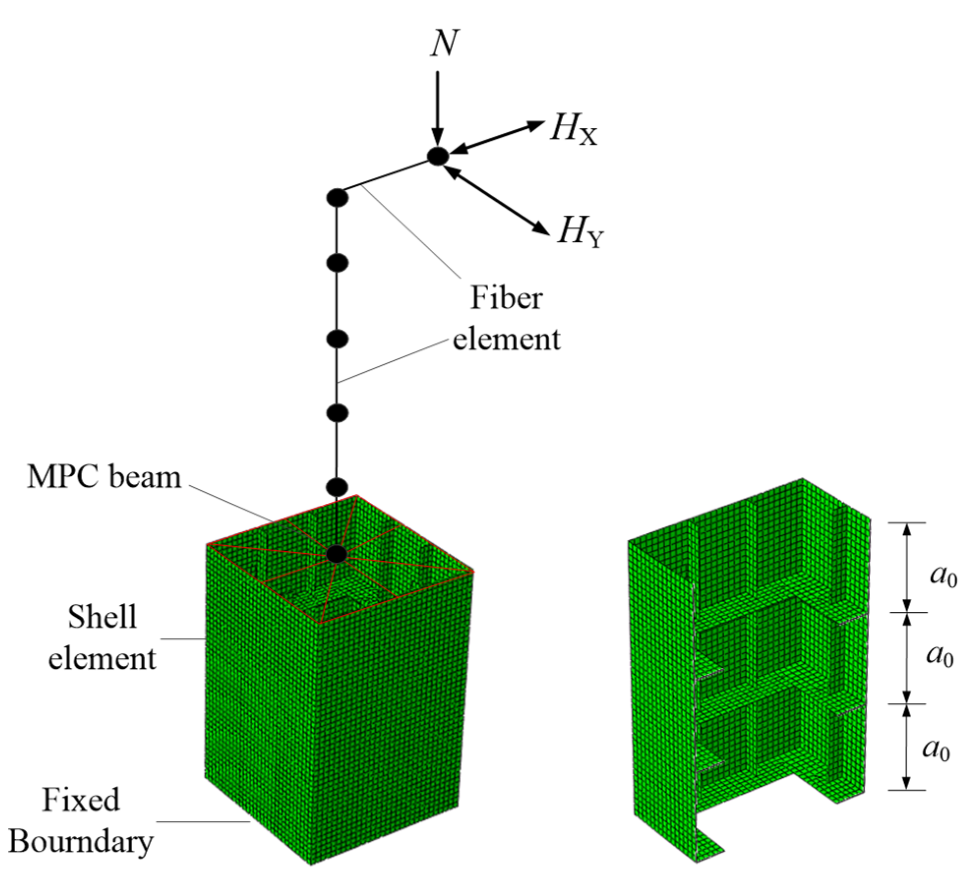
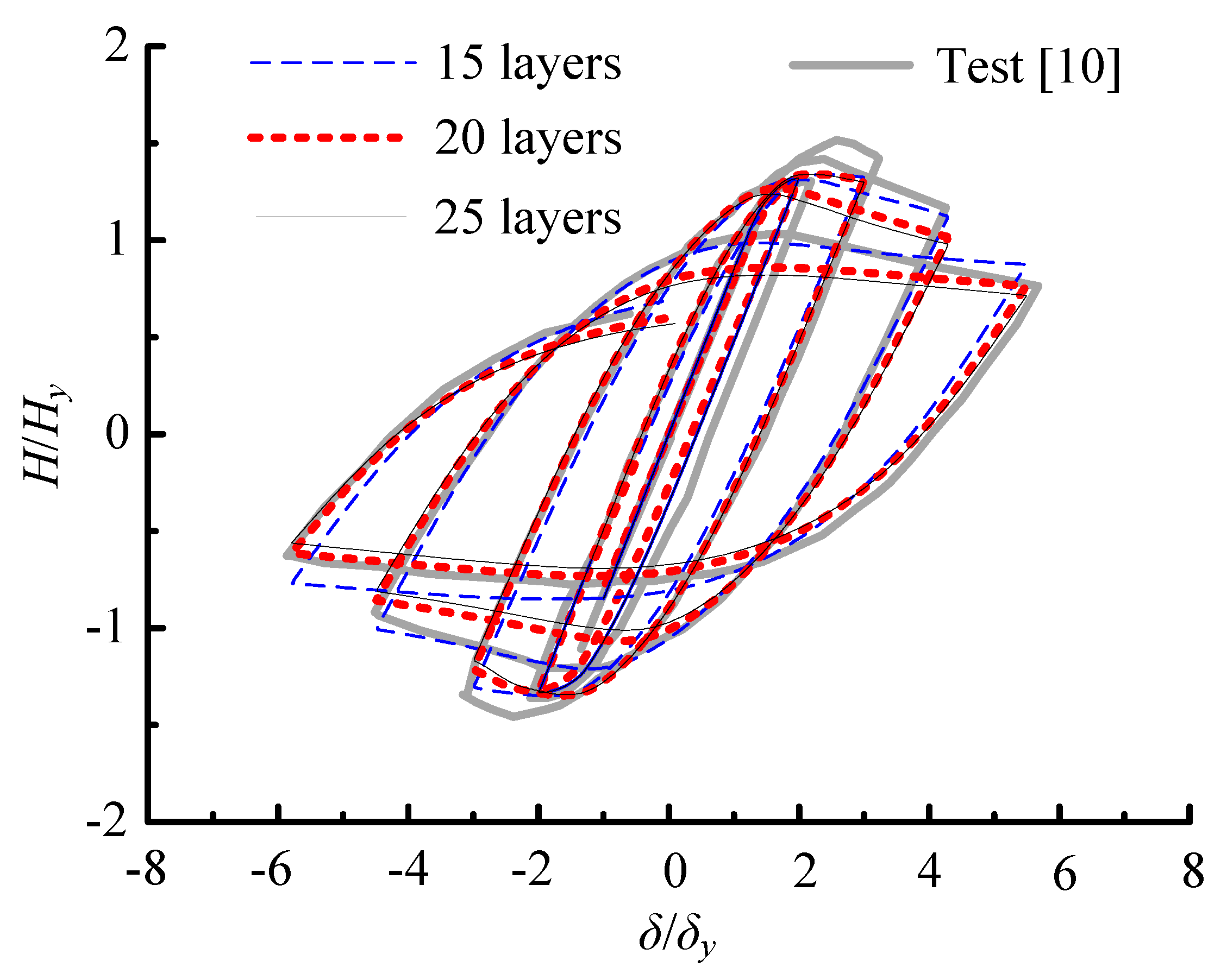
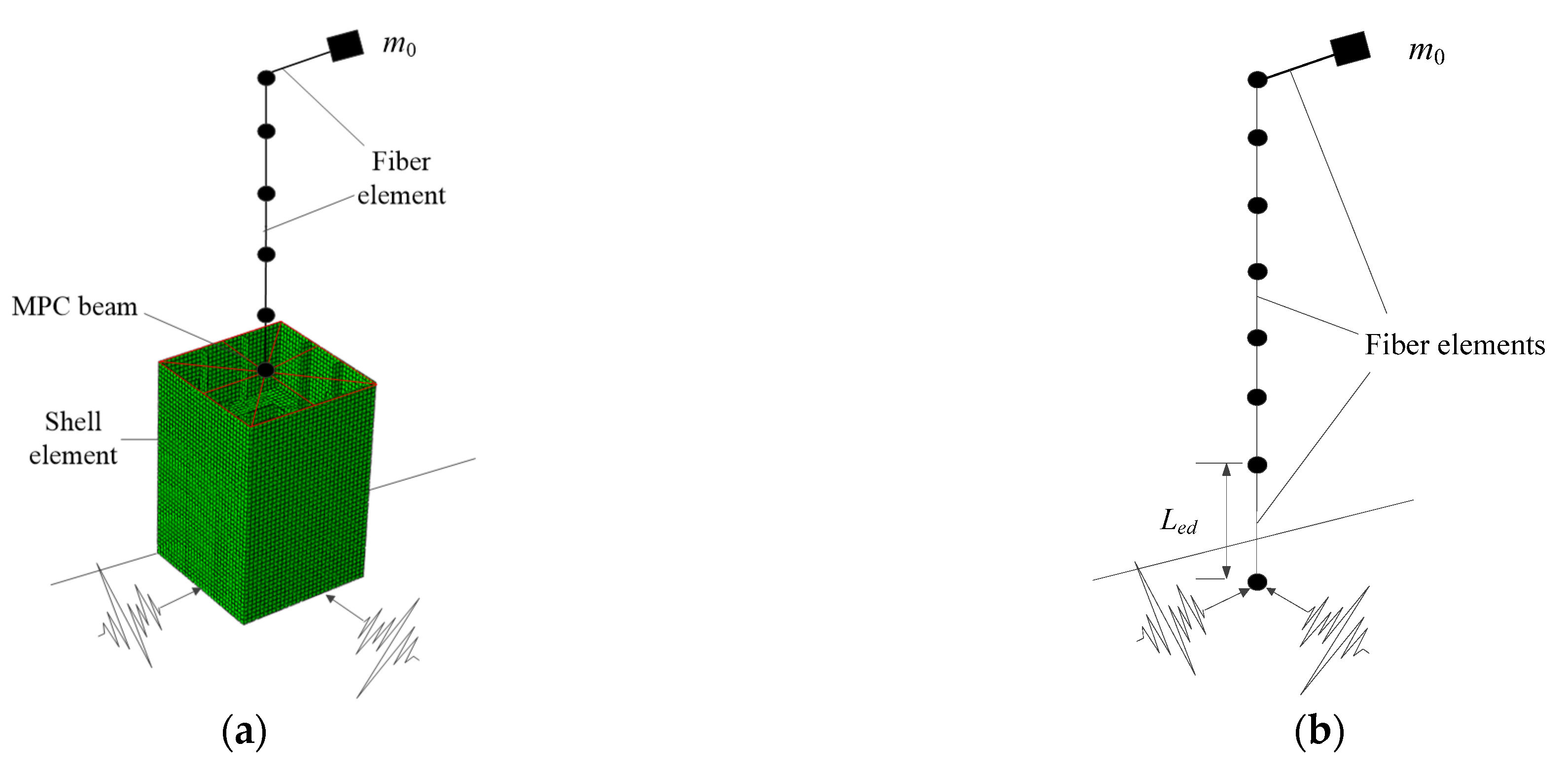
2.2. Hybrid-Element Model

To study the seismic performance and practical calculation method of the seismic response of eccentrically compressed steel piers, the hybrid-element models, which are combined with fiber elements and shell elements for multiple steel piers, were established in the common FE software ABAQUS 6.14 to perform the pseudo-static numerical simulation analysis. Figure 2 shows the horizontal bidirectional pseudo-static analysis model of a typical eccentrically compressed steel pier with a square-stiffened section. The height of the pier is h, the diaphragm spacing is a0, and the fixed boundary condition is applied at the bottom of the pier. The vertical constant axial force N and horizontal cyclic loads HX and HY were applied at a distance of e (i.e., the eccentricity) from the center of the section. In this case, note that the subscript X represents the horizontal direction in the eccentric plane, i.e., the transverse direction of the actual bridge, whereas Y represents the out-of-plane horizontal direction perpendicular to the X-direction, i.e., the longitudinal direction of the actual bridge.
For the material elastoplastic constitutive model, the bilinear kinematic and isotropic hardening models are traditional nonlinear hysteretic constitutive steel models. However, these two models can only consider the Bauschinger effect or the strain-strengthening effect separately. Actual steel has these two performances simultaneously, so these two constitutive models have limited accuracy when applied to steel piers with significant plastic strain history and local instability behavior [32]. To improve the calculation accuracy, this study adopts the modified two-surface hysteretic constitutive model modified by Shen et al. [33,34], which has been widely used in the seismic response analysis of steel piers [4,12,13,18,19,27,28]. Wang et al. [35] further modified this constitutive model locally to avoid the defect of unreasonable hysteresis history under slight cyclic loading.
The modified two-surface model was used, which is realized by programing and calling the UMAT subroutine in ABAQUS. The steel type used in this paper was Q345qC, a kind of structural steel alloy widely used in bridge engineering in China. The material parameters of the modified two-surface model constitutive model were calibrated by Wang et al. [35] (Table 2). The detailed meaning of each material parameter can be found in the literature [33,34,35].
To reflect the local instability effect of steel plates that may occur at the bottom of piers, shell elements were established within the range of thrice the spacing of the transverse diaphragms, which can cover the area where local buckling deformation occurs [31]. Fiber elements were established in the remaining part (Figure 2). The shell element type is a four-node reduced integral isoparametric element (S4R) in Abaqus, and there are five integration points in the element’s thickness direction. The fiber-element type is a two-node linear spatial beam element (B31).
In order to determine the reasonable shell element size to model the local instability behavior, the mesh size sensitivity analysis was carried out by comparing the calculation results and pseudo-static test results of a square-section steel pier in the literature [10]. The material and structural parameters of the tested pier are shown in Table 3 and Table 4, respectively. Within the length of diaphragm spacing, 15, 20 and 25 layers of shell elements were divided in three different models. The comparison between the calculation results of the load–displacement curve at the top of the pier and the test results in the literature [10] is shown in Figure 3. In the figure, H and Hy are the horizontal force and the cross-section yield force, respectively. It can be seen from the figure that, when the length is divided into 20 layers, the curve shows a certain difference from that obtained by the 15-layer model, but it is quite close to the curve of the 25-layer model. Meanwhile, it is very close to the tested curve. Therefore, in this paper, the hybrid-element models were established uniformly with the mesh density of the 20-layer shell elements within the length of diaphragm spacing.
Moreover, the multipoint coupling (MPC) function in Abaqus was used to simulate the deformation relationship between the shell and fiber elements at the interface section. According to the existing research conclusions [4,11,18,36], the hybrid-element calculation model can accurately reflect the local instability effect of the steel plates at the bottom of piers. Additionally, this kind of model can improve the calculation efficiency compared with fully shell-element models.

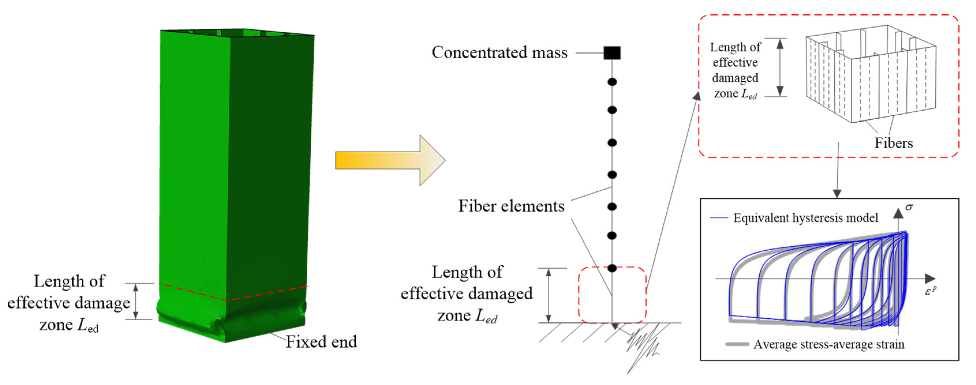
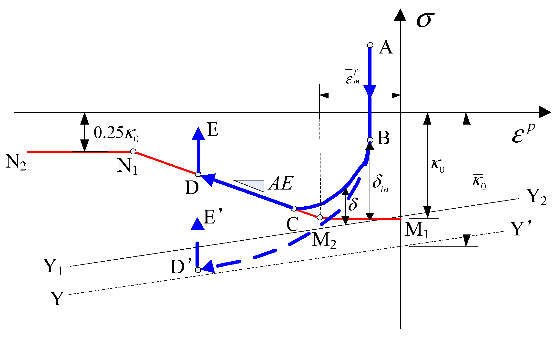
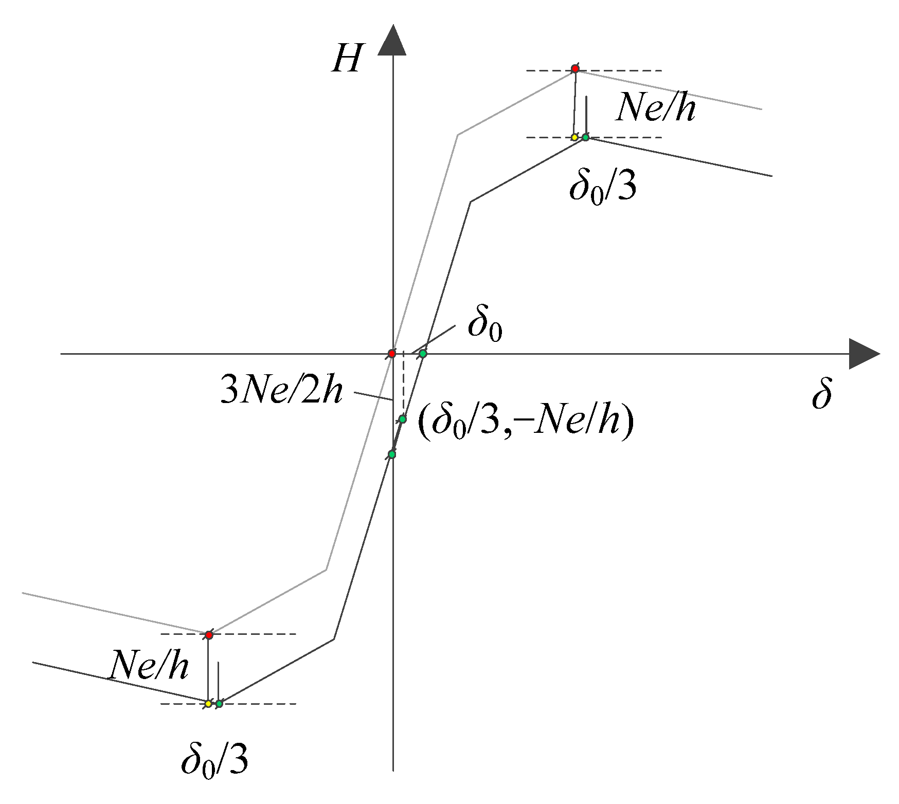
3. Review of the Improved Fiber Model

To establish a high-precision calculation model for centrally compressed square-section steel piers that can be used in horizontal bidirectional seismic response analysis, previous studies [18,19] proposed a kind of fiber model that can accurately consider the local instability of steel plates. Figure 4 shows a schematic of the basic principle of this improved fiber model. It can be seen from Figure 4 that the core idea of the model is to use an equivalent hysteresis model as the constitutive relationship of the fiber element in the length of the effective seismic damaged zone Led at the bottom of the pier to reflect the local instability effect of the steel plates.
Since the local instability effect of steel plates distorts the section, the traditional fiber model based on the plane cross-section assumption and the material elastoplastic constitutive relationship becomes inapplicable. Therefore, in the improved fiber model that can consider local instability effect, it is firstly necessary to determine the length of the effective seismic damaged zone, Led, where the steel plates may undergo local instability deformation and the plane cross-section assumption is no longer applicable. Only one fiber element will be established in this area. The empirical value formula for Led given in [18,19] is shown below.
L ed = L w min [ 0.7 B 0 , a 0 ]
where Lw is the half length of a buckling wave of steel plates.
Furthermore, it is necessary to establish the equivalent stress–strain hysteresis model of the fiber element within Led. Figure 4 shows that this hysteretic model was established by fitting the axial average-stress–average-strain relationship within Led obtained by the hybrid-element calculation model.
To unify the constitutive relationship of the fiber elements in other regions, the modified two-surface uniaxial constitutive steel model was selected as the initial form of the equivalent hysteretic model. By comparing the average-stress–average-strain relationship and the stress–strain relationship of the steel modified two-surface model, it can be seen that, because the steel plates undergo out-of-plane geometric deformation after local instability, the geometric deformation of the steel plates is restored when reverse tension is applied. Thus, the axial stiffness of the fiber element within Led must be reduced. According to the characteristics of the average-stress–average-strain curve, the fiber element in the effective seismic damaged zone adopted the following equivalent elastic modulus E′:
E = { E , ε ¯ ε ¯ m E k e m ε ¯ , ε ¯ < ε ¯ m
where ε ¯ is the current strain, ε ¯ m is the average strain value corresponding to the peak value of the horizontal displacement load, E is the elastic modulus value of the steel alloy, and k and m are equivalent hysteretic model parameters. Through the parameter analysis of several centrally compressed steel piers, the fitting formulas were obtained in the literature [18], as follows:
{ k = 0.951 R R 0.981 λ 0.186 α 0.333 ( N N y ) 0.286 L ed 0.322 ( γ γ ) 0.080 m = 28.578 R R 1.635 λ 0.345 α 0.178 ( N N y ) 0.260 L ed 0.260 ( γ γ ) 0.244 k 2.016
After determining the equivalent elastic modulus, the average plastic strain can be calculated as follows and the stress–strain relationship can be translated into the stress–plastic strain relationship.
ε ¯ p = ε σ ¯ E
Furthermore, Figure 4 shows that, due to the local buckling of the steel plates, the average-stress–plastic strain curve produces a negative stiffness in the compression section. To describe the characteristics of the deformation history, the compression section of the stress–plastic strain path ABCDE (blue solid line in Figure 5) was introduced, based on the initial stress–plastic strain curve ABD’E’ (blue dotted line in Figure 5) of the material two-surface model. The initial value of the compressive skeleton curve M1M2N1N2 (red solid line in Figure 5) is σy. When the plastic strain ε ¯ p lower than the peak average plastic strain ε ¯ m p , the skeleton curve decreases with the slope AE, and remains unchanged until reaching to 0.25 times the σy. It can be seen from Formula (3) that, when the strain is equal to ε ¯ m , the elastic modulus does not need to be reduced, so the peak average plastic strain ε ¯ m p in the figure can be calculated as follows:
ε ¯ m p = ε ¯ m σ y E
Figure 5 also shows that the bounding surface YY’ of the modified two-surface model must be removed to Y1Y2 to obtain a reasonable result. Therefore, it is necessary to define the bounding-surface reduction law of the equivalent hysteretic model after local instability deformation occurs, and the radius of the elastic range should also be reduced. According to the trial calculation, the initial radius of the bounding surfaces in the equivalent hysteresis model was modified to
κ ¯ 0 1 = B κ ¯ 0
where B is the model parameter. The modified bounding surface radius and elastic range radius can be calculated by
κ ¯ 1 = κ ¯ ( ε ¯ m p ε ¯ 1 p ) C E
κ 1 = κ [ E 0 P + ( A + C ) E ] ( ε ¯ m p ε ¯ 1 p ) 2
where C is the model parameter and ε ¯ 1 p is the plastic strain from the previous compression-to-tension turning point in the strain history. κ ¯ and κ are the radii of the elastic range and the bounding surface of the material two-surface model, respectively. The remaining parameters are the same as previously used. The fitting formulas of model parameters ε ¯ m p , A, B, and C are also obtained through the statistics of the many parameter-analysis results of steel piers. The results are given as follows, fitted in the literature [18].
ε ¯ m p = 0.00163 R R 3.00 λ 0.208 α 0 0.203 N N y 0.305 L ed 0.053 γ γ 0.435 A = 0.445 R R 1.387 λ 0.744 α 0 0.284 N N y 0.693 L ed 0.312 γ γ 0.504 B = 1.095 R R 0.122 λ 0.182 α 0 0.091 N N y 0.104 L ed 0.029 γ γ 0.006 C = 1.370 R R 0.929 λ 1.889 α 0 0.299 N N y 0.985 L ed 0.432 γ γ 0.197
The fitting Formulas (4) and (10) of the model parameters apply to the centrally compressed steel piers made of Q345qC bridge steel, and the structural parameters must satisfy 0.039 ≤ RR ≤ 0.052, 0.22 ≤ λ ≤ 0.40, 0.5 ≤ α ≤ 1.0, 0.1 ≤ N/Ny ≤ 0.3, and 1.0 ≤ γ/γ* ≤ 3.0. By comparing the FE simulation and test results, the improved fiber model of the square-section steel piers without eccentricity has a high calculation accuracy and is suitable for structural seismic response calculation under rarely met horizontal bidirectional earthquake actions [18,19].
Figure 6 shows the calculation flow chart for the global stiffness matrix of the improved fiber model of the square-section steel piers. In the figure, N0 is the total number of elements and M is the total number of load increment steps. In the engineering design, the structural seismic demand analysis can be carried out according to the steps in the flow chart.

4. Calculation and Discussion for Eccentrically Compressed Steel Piers

Under the action of a horizontal bidirectional earthquake, eccentrically compressed steel piers are subjected to the combined effect of eccentric axial force and in-plane and out-of-plane horizontal seismic forces. In this paper, the pseudo-static analysis was performed, and the steel piers presented in Table 1 were considered as the research object to study the applicability of the improved fiber model in the in-plane and out-of-plane directions for the eccentrically compressed steel piers. Obviously, the actual eccentricity needs to be considered when establishing the fiber model of the eccentrically compressed steel pier, and the model is different from that of the centrally compressed steel pier in Figure 4.

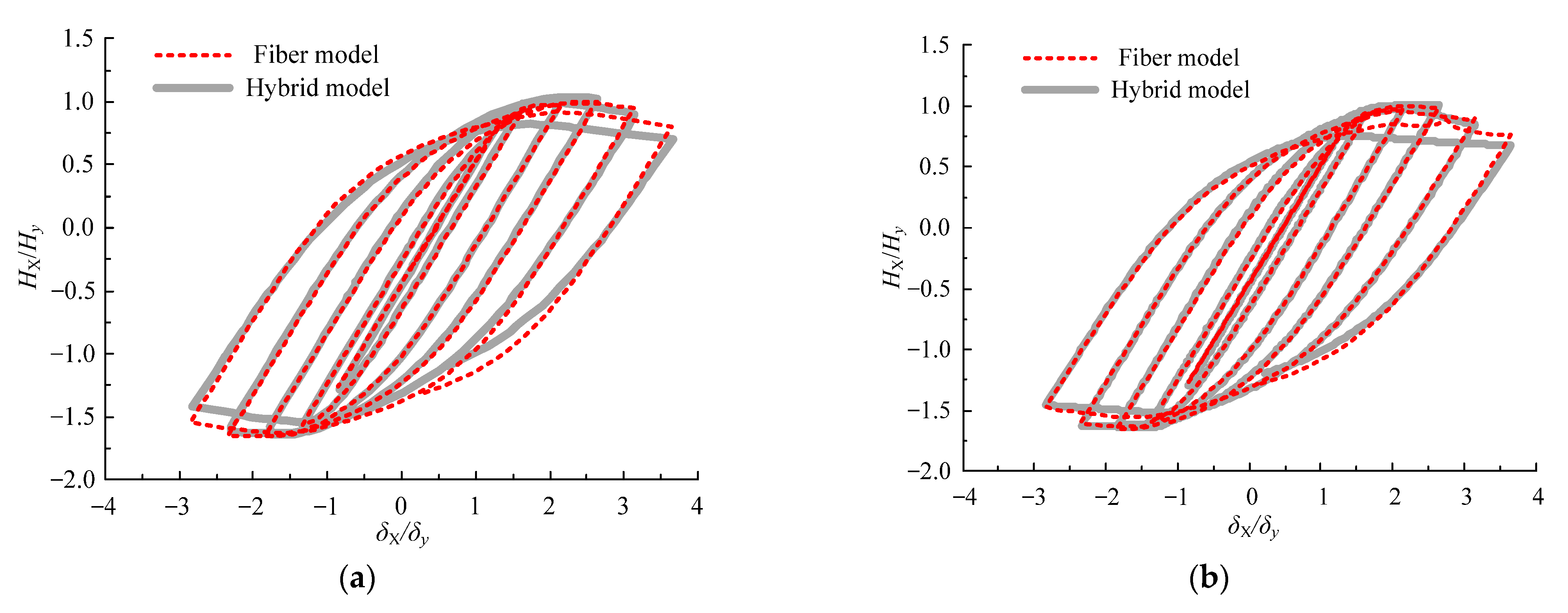
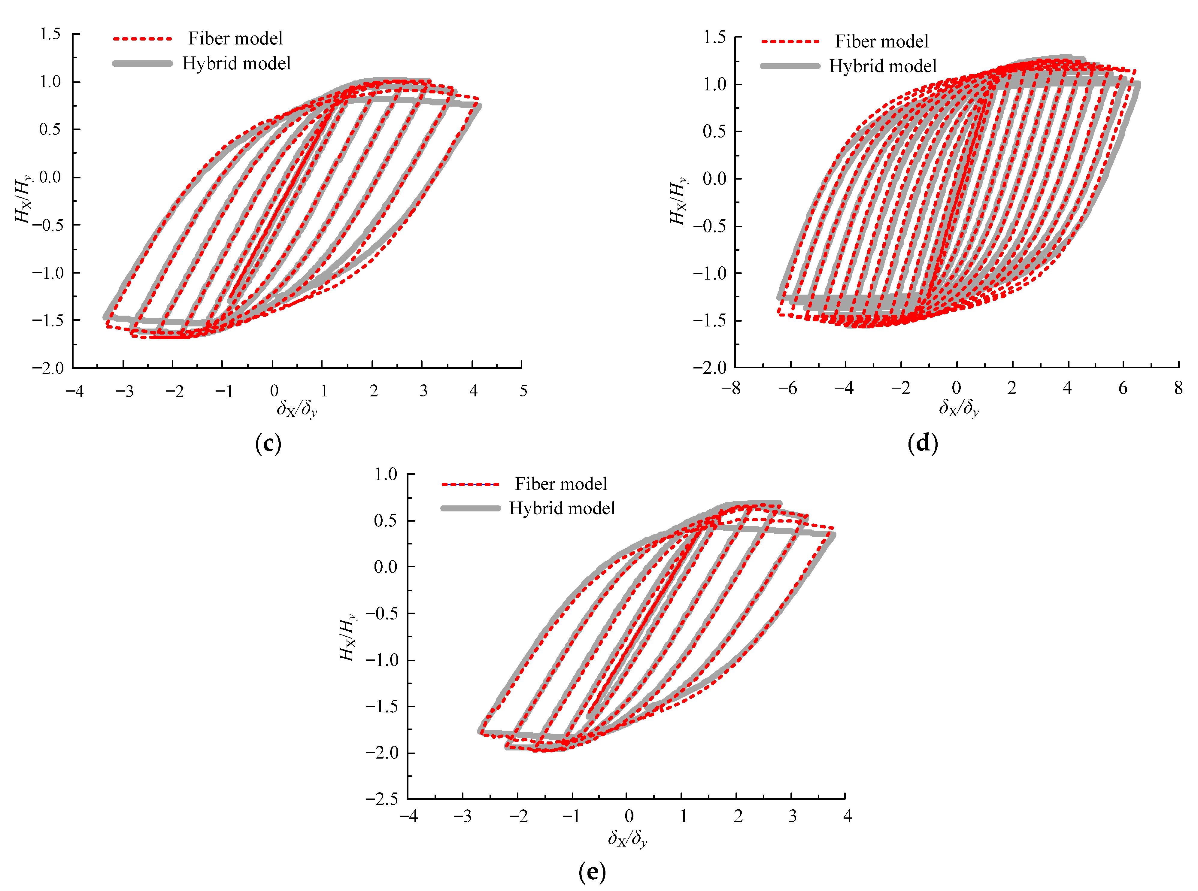
4.1. In-Plane Pseudo-Static Analysis

Figure 2 shows that, under the action of the eccentric constant axial compression N and the horizontal cyclic load HX in the plane, the steel piers are subjected to the eccentric bending moment Ne additionally. Since N is applied first, the structure produces the initial eccentric displacement δ0. Gao et al. [23] concluded that the force–displacement hysteresis curves of the eccentrically compressed rectangular- or circular-section steel piers under the in-plane horizontal earthquake could be directly obtained by translating those of the centrally loaded steel piers. Figure 6 shows the skeleton lines of the hysteresis curves of steel piers under the action of eccentric or centrally loaded compression and in-plane horizontal force. Figure 7 shows that the vector requiring translation is (δ0/3, −Ne/h). In addition, it is easily discerned that the bearing capacity and ductility performance indexes of the structures must be translated along the same vector.
To study the applicability of the improved fiber model in in-plane pseudo-static analysis, the hysteresis curves of the centrally loaded steel piers under in-plane horizontal cyclic loads obtained using the fiber-shell hybrid-element calculation models were directly removed along the vector (δ0/3, −Ne/h) to obtain the hysteretic curves of the eccentrically compressed steel piers. The hysteresis curves of the centrally loaded steel piers were obtained in the literature [18] through the FE analysis of hybrid-element models. To be consistent with the displacement loading history of the hybrid-element calculation model, the horizontal displacement loading form for fiber models was modified based on the loading forms for the centrally loaded piers (Figure 8). This loading form has been used in several papers [11,18,19,36], and this paper adds the effect of eccentricity-induced initial displacement. The initial displacement is defined as δ0, and the forced displacements are translated by δ0/3 along the positive X-direction. Moreover, the peak displacement increment of each cycle is δy/2. Previous studies [11,18,19] consider the state when the bearing capacity of the steel piers in the horizontal direction decreases to 80% of the peak value as the limiting state. Therefore, in this pseudo-static analysis, the state when the bearing capacity obtained using the hybrid-element calculation models decreased to 80% of the peak value was considered as the structural limiting state, and the loading stopped.
The load–displacement calculation results between the improved fiber and hybrid-element calculation models in the in-plane direction of piers in Table 1 were thoroughly compared. Due to space limitations and to be as comprehensively as possible to show the influence of different kinds of structural parameters, the load–displacement curve results of each pier shown in bold in Table 1 are given in Figure 9.
Figure 9 shows that each pier’s load–displacement curve, calculated according to the improved fiber model, is quite close to that obtained using the hybrid-element calculation model, and other piers in Table 1 also have similar comparison results.
The key data of the in-plane calculation results obtained by the two models are given in Table 5, including the initial stiffness, the maximum bearing capacity, the displacement corresponding to the maximum bearing capacity (δm), the displacement corresponding to the bearing capacity dropped to 80% of the maximum value (δ80), and the total hysteretic energy. These data were all obtained according to Figure 9 and were, therefore, dimensionless. It can be seen from the table that the results obtained by the improved fiber model are quite close to those obtained by the hybrid model, while the error is within an acceptable range.
Thus, the improved fiber model can accurately simulate the influence of the eccentric bending moment, reflecting the process of increasing the bearing capacity, reaching the ultimate bearing capacity, and degrading the bearing capacity of the steel piers. It is verified that the improved fiber model is suitable for the in-plane seismic response calculation of steel piers under eccentric compression.

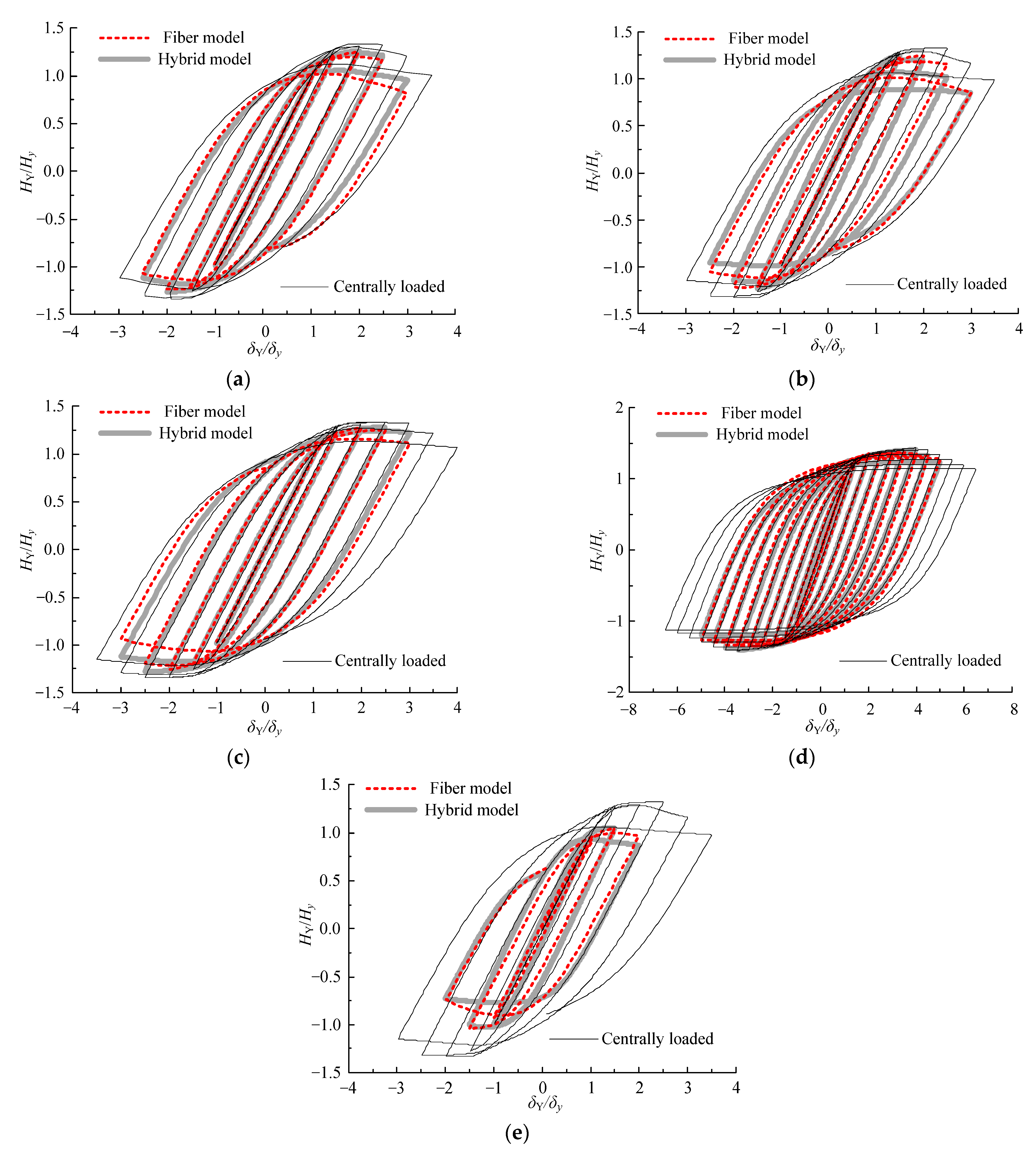
4.2. Out-of-Plane Pseudo-Static Analysis

Figure 2 shows that, under the action of the eccentric compression N and the out-of-plane eccentric horizontal cyclic load HY, the steel piers are subjected to the torsional moment HYe and the bending moment Ne. Goto et al. [25] confirmed that the restraint of the upper bearings should be considered when studying a single steel pier, i.e., the torsional deformation should be restrained. Therefore, this study restrained the torsional deformation of the steel pier under eccentric compression. Although the recommended formula of the scale coefficient for the bearing capacity and ductility performance index between the eccentric and centrally loaded rectangular-section steel piers under out-of-plane horizontal earthquakes was given in a previous study [27,28], the relationship between the hysteresis curves of these two kinds of structures remains unclear. Therefore, each pier’s hybrid-element calculation models (Figure 2) were established to perform the out-of-plane numerical simulation analysis in this paper. When performing the out-of-plane pseudo-static analysis for the eccentrically compressed steel piers, the adopted displacement loading form is the same as that used in the pseudo-static analysis of the centrally loaded steel piers (Figure 10) [11,18,19].
Out-of-plane horizontal pseudo-static numerical simulations were conducted through the improved-fiber and hybrid-element calculation models for piers, as shown in Table 1. Figure 11 shows the calculation results of the out-of-plane load–displacement curve of each pier, as shown in bold in Table 1. The hysteresis curve results of the corresponding steel piers without eccentricity are also plotted in the figure to reflect the influence of eccentric compression. The calculation results show that, due to the eccentric bending moment effect, the maximum structural bearing capacity is worse than that of the steel piers without eccentricity, and the ductility is also reduced. Therefore, eccentrically compressed piers will attain the limiting state in advance. Because the torsional deformation is restrained, the stiffness does not change in an obvious manner. Furthermore, each pier’s load–displacement curve in Figure 11, calculated according to the improved fiber model, is quite close to that obtained using the hybrid-element calculation model, and other piers in Table 1 also have similar comparison results.
The key data of the out-of-plane calculation results obtained by the two models are given in Table 6, including the initial stiffness, the maximum bearing capacity, the displacement corresponding to the maximum bearing capacity (δm), the displacement corresponding to the bearing capacity dropped to 80% of the maximum value (δ80), and the total hysteretic energy. It can be seen from the table that the results obtained by the improved fiber model are quite close to those obtained by the hybrid model, while the error is within an acceptable range.
It can be observed that, when performing a horizontal cyclic pseudo-static analysis in the out-of-plane direction for the eccentrically compressed steel piers, the improved fiber model can also reflect the influence of increased local instability on the compressed side and accurately simulate the structural elastoplastic hysteretic performance in the out-of-plane direction, and other piers in Table 1 also have similar comparison results.
By establishing improved fiber models, the pseudo-static analysis of the eccentrically compressed steel piers in the in-plane and out-of-plane horizontal directions was conducted. The calculation results were compared with those of the refined hybrid-element calculation models. It was confirmed that the improved fiber model could accurately simulate the structural deformation characteristics in the local instability area under in-plane or out-of-plane horizontal loads, so the calculation accuracy in both directions was high. Next, the improved fiber model is used to calculate the horizontal bidirectional elastoplastic seismic response of the steel piers.

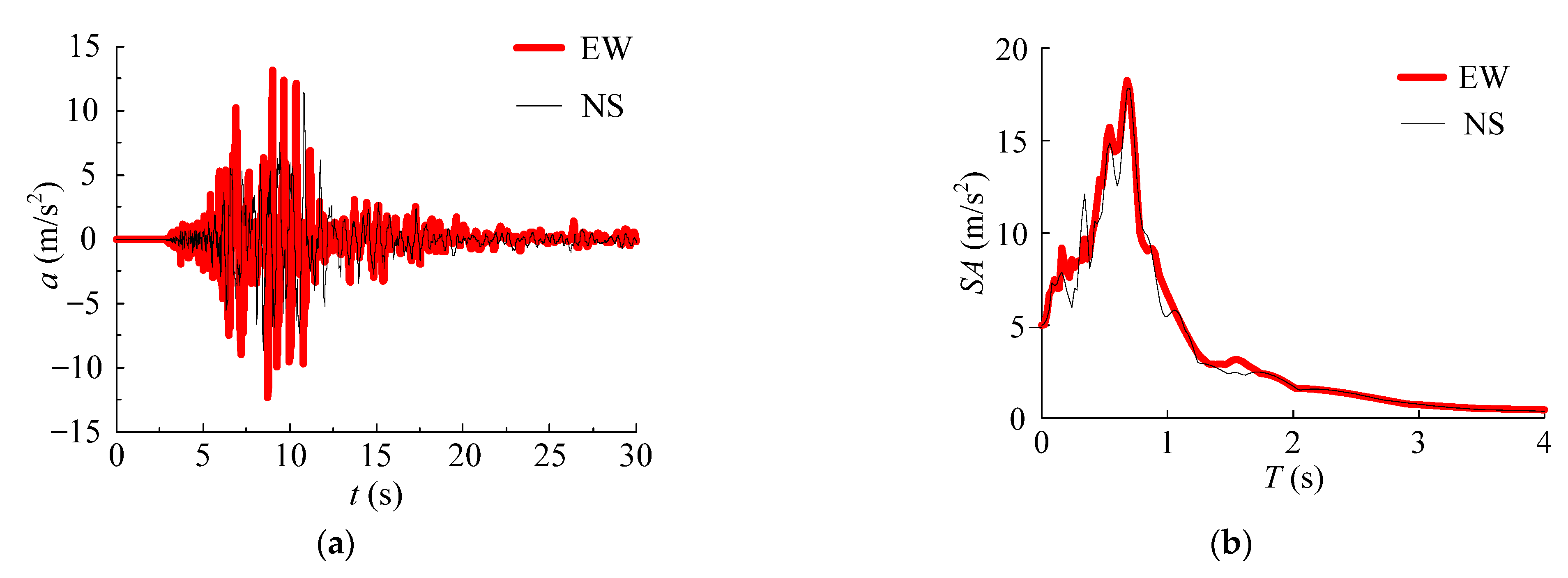
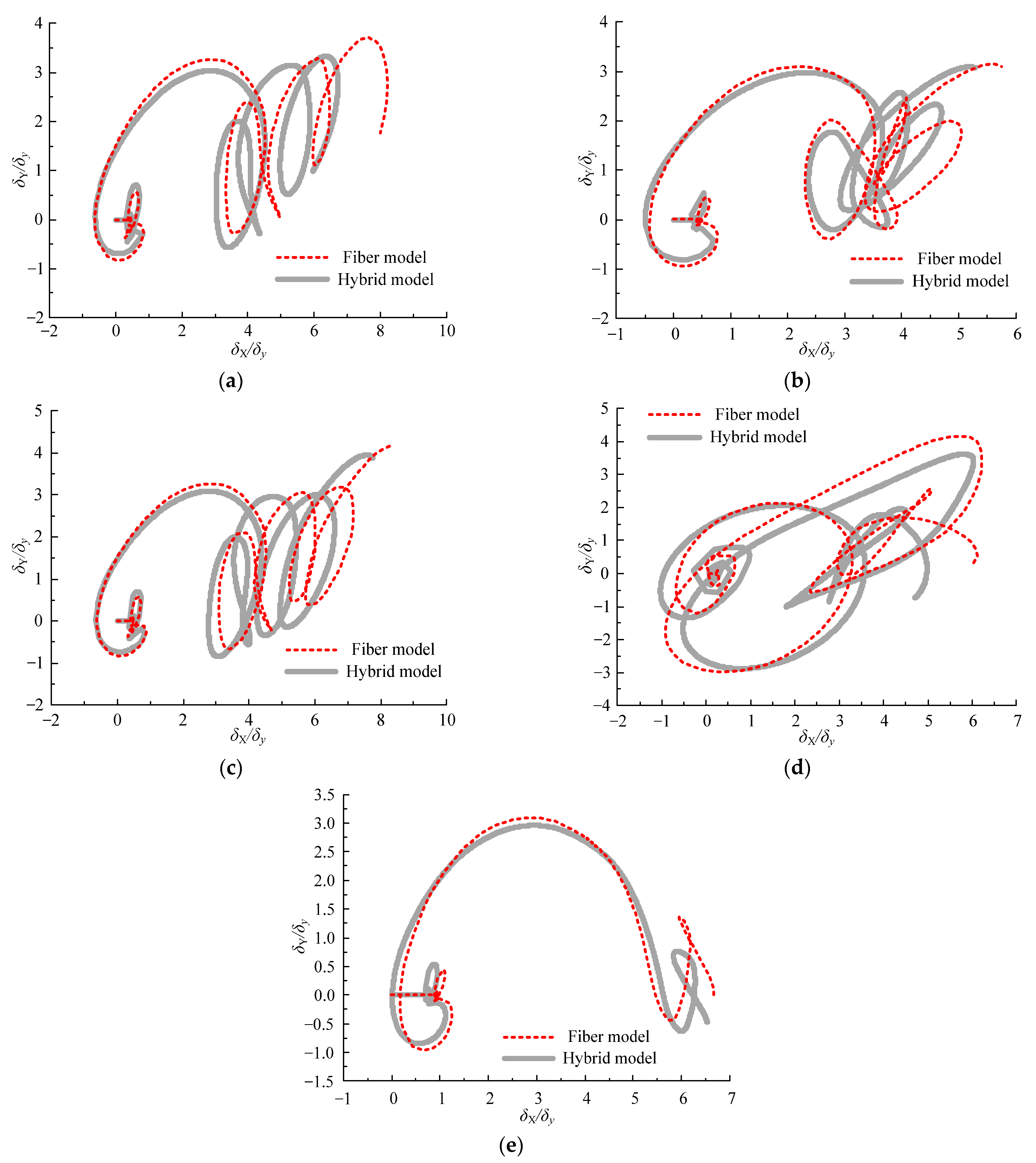
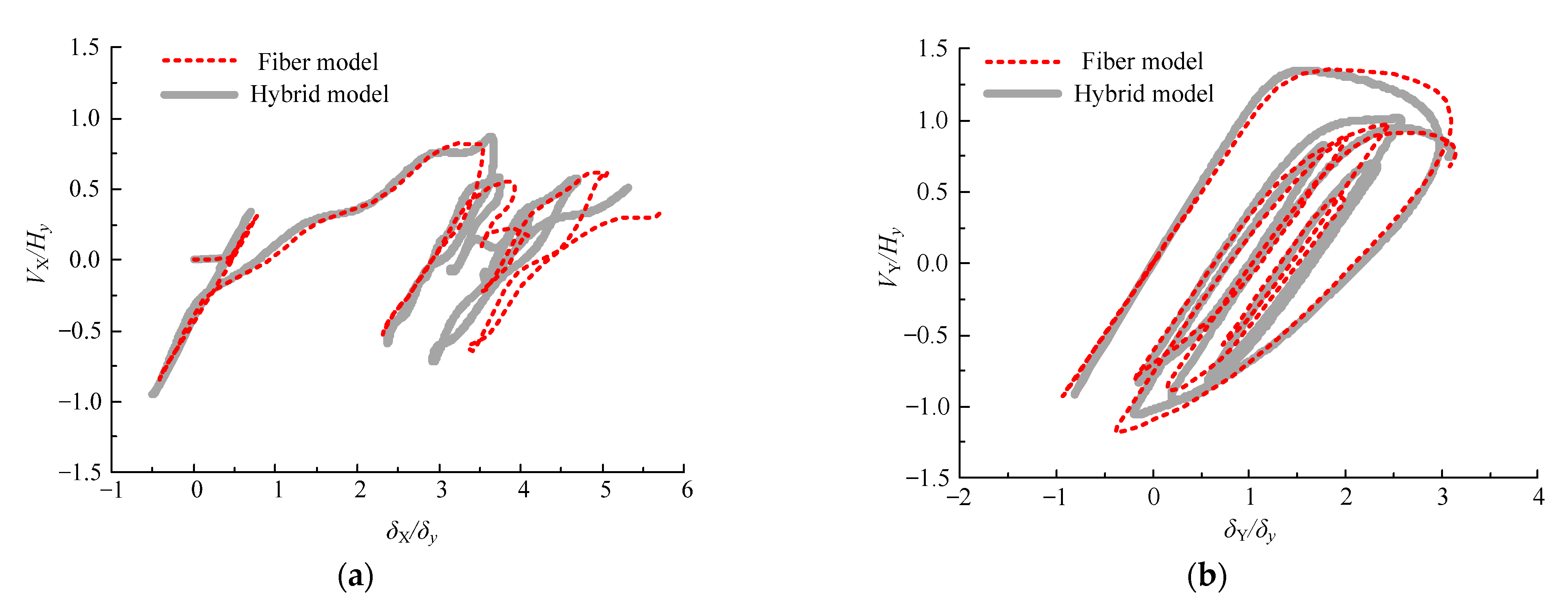
4.3. Seismic Response Analysis

To further verify the applicability of the improved fiber model in seismic response analysis for eccentrically compressed steel piers, considering the five groups of piers marked in bold font in Table 1 as an example, improved fiber models were established to calculate the structural seismic response under horizontal bidirectional earthquakes. Simultaneously, hybrid-element calculation models were also established for comparison. Figure 12 shows the schematics of the two models used in the seismic response analysis. The axial force in the pseudo-static analysis model was converted into the pier top mass m0.
To verify the structural applicability under actual horizontal bi-directional earthquakes, ground motions were input simultaneously along the two main axis directions at the bottom of the pier. NS waves were input along the X-direction (in-plane direction), whereas the EW waves were input along the Y-direction (out-of-plane direction). The EW and NS ground motion inputs use the acceleration waves from the Niigata earthquake in Japan recorded by JMA (2004) [37]. The earthquake record is not related with the bridge design. Figure 13 shows the acceleration waves and response spectra of the EW and NS inputs, where a represents the acceleration and SA represents the acceleration response spectrum.
Figure 14 shows the calculation results of the displacement trajectory at the top of the eccentrically compressed steel piers. The parameters of these piers are shown in bold in Table 1. Taking the b3 pier as an example, the shear force–displacement curves in the in-plane (X) and out-of-plane (Y) directions are given in Figure 15. The calculation results of the horizontal bidirectional displacement trajectory and shear force–displacement curves obtained using the improved fiber model are basically consistent with those obtained using the hybrid-element calculation model.
Under the action of horizontal bidirectional earthquakes, the overall deformation in the in-plane direction >> that in the out-of-plane direction for the eccentrically compressed steel piers. This trend is due to the eccentric compression causing the piers to move toward the eccentric side in the plane. Combined with Figure 11, it is evident that the deformation in the in-plane direction adversely affects the structural bearing capacity and stiffness in the out-of-plane direction, which deteriorates the seismic performance of the structures.
At the same time, the key data comparison of the horizontal bidirectional seismic response calculation results obtained by the two kind of models is given in Table 7, including the maximum displacement and residual displacement, δm and δr, respectively, in the X and Y directions, and the first-order frequency f. As can be seen from the table, the results obtained by the improved fiber model are very close to those obtained by the hybrid model, while the error is within an acceptable range. In Figure 16, the calculation results of the local deformation of the hybrid model at the same time point are given. It can be seen that the local deformation is within the height of the Led at the bottom of the pier, and the increase in the eccentricity aggravates the degree of local deformation.
The above results further verify that the proposed equivalent hysteresis model and improved fiber model have a high calculation accuracy and good applicability for eccentrically compressed steel piers. Thus, the improved fiber model can be directly used in engineering to analyze the seismic response of eccentrically compressed square-section steel piers under different rarely met earthquakes, according to the flow chart in Figure 6.

5. Conclusions and Discussion

This study focuses on a horizontal bidirectional seismic response calculation method for eccentrically compressed steel piers. An improved fiber model for centrally compressed steel piers considering the local instability effect was introduced. The improved fiber and hybrid-element calculation models were established and the in-plane and out-of-plane pseudo-static analysis and horizontal bidirectional seismic response analysis of the eccentrically compressed steel piers were conducted. The following conclusions were obtained.
(1)
The hysteretic curves in the in-plane direction of the eccentrically compressed steel piers can be obtained by translating those of the centrally compressed piers. The improved fiber model can accurately simulate the hysteretic performance of the structures in the in-plane direction;
(2)
The bearing capacity and ductility of the eccentrically compressed steel piers in the out-of-plane direction are lower than those of the centrally compressed piers. The improved fiber model can also accurately calculate the structural hysteretic performance in the out-of-plane direction;
(3)
By taking five piers as examples, the improved fiber model was used to analyze the horizontal bidirectional seismic response of the eccentrically compressed steel piers. The results show that this kind of beam-based model can obtain accurate seismic response analysis results.
The research in this paper provides guidance for the application of the improved fiber model to the seismic demand calculation of eccentrically compressed steel piers. It was verified that the seismic response of the eccentrically compressed steel piers can be directly calculated by using the improved hysteresis model after actual modeling without making more modifications and avoiding some troublesome operations, such as using specific bending moment-curvature model or other fiber sections.
It should be noted that the bridge seismic performances and the seismic evaluation methods are another important issue. The existing seismic-performance-checking methods are all based on the results of shell-element models, resulting in the incompatibility between the seismic capacity and demand values. Therefore, the seismic evaluation method based on the improved fiber model should also be proposed for eccentrically compressed steel piers, which needs further study.

Author Contributions

Conceptualization, X.Z.; Funding acquisition, H.Z.; Investigation, Z.T.; Validation, F.S.; Writing—review & editing, H.Z. All authors have read and agreed to the published version of the manuscript.

Funding

This research was funded by the General Program of National Natural Science Foundation of China, Grant No. 51878606.

Institutional Review Board Statement

Not applicable.

Informed Consent Statement

Not applicable.

Data Availability Statement

Not applicable.

Acknowledgments

The authors would like to express their gratitude to Dassault Systèmes Simulia Corporation for allowing the use of their powerful commercial FE package-ABAQUS6.14 during this research.

Conflicts of Interest

The authors declare no conflict of interest.

References

  1. Watanabe, E.; Sugiura, K.; Nagata, K.; Kitane, Y. Performances and damages to steel structures during the 1995 Hyogoken-Nanbu earthquake. Eng. Struct. 1998, 20, 282–290. [Google Scholar] [CrossRef]
  2. Usami, T. Guidelines for Seismic and Damage Control Design of Steel Bridges; Gihodo Shuppan Co., Ltd.: Tokyo, Japan, 2007. [Google Scholar]
  3. Ge, H.; Gao, S.; Usami, T.; Matsumura, T. Numerical Study on Cyclic Elasto-plastic Behavior of Steel Bridge Piers of Pipe-Sections without Stiffeners. Doboku Gakkai Ronbunshu 1997, 1997, 181–190. [Google Scholar] [CrossRef] [Green Version]
  4. Zheng, Y.; Usami, T.; Ge, H.B. Ductility evaluation procedure for thin-walled steel structures. J. Struct. Eng. 2000, 126, 1312–1319. [Google Scholar] [CrossRef]
  5. Watanabe, E.; Sugiura, K.; Oyawa, W.O. Effects of multi-directional displacement paths on the cyclic behaviour of rectangular hollow steel columns. Doboku Gakkai Ronbunshu 2000, 2000, 79–95. [Google Scholar] [CrossRef] [Green Version]
  6. Goto, Y.; Jiang, K.; Obata, M. Hysteretic behavior of thin-walled circular steel columns under cyclic biaxial loading. Doboku Gakkai Ronbunshu 2005, 2005, 181–198. [Google Scholar] [CrossRef] [Green Version]
  7. Goto, Y.; Jiang, K.; Obata, M. Hysteretic behavior of thin-walled stiffened rectangular steel columns under cyclic bi-directional loading. Doboku Gakkai Ronbunshuu A 2007, 63, 122–141. [Google Scholar] [CrossRef] [Green Version]
  8. Goto, Y.; Koyama, R.; Fujii, Y.; Obata, M. Ultimate state of thin-walled stiffened rectangular steel columns under bi-directional seismic excitations. Doboku Gakkai Ronbunshuu A 2009, 65, 61–80. [Google Scholar] [CrossRef] [Green Version]
  9. Dang, J.; Nakamura, T.; Aoki, T.; Suzuki, M. Bi-directional loading hybrid test of square section steel piers. J. Struct. Eng. A 2010, 56A, 367–380. [Google Scholar]
  10. Usami, T.; Gao, S.B.; Ge, H.B. Stiffened steel box columns. Part 2: Ductility evaluation. Earthq. Eng. Struct. Dyn. 2000, 29, 1707–1722. [Google Scholar] [CrossRef]
  11. Chen, S.X.; Xie, X.; Zhuge, H.Q. Hysteretic model for steel piers considering the local buckling of steel plates. Eng. Struct. 2019, 183, 303–318. [Google Scholar] [CrossRef]
  12. Zheng, Y.; Usami, T.; Ge, H.B. Ductility of thin-walled steel box stub-columns. J. Struct. Eng. 2000, 126, 1304–1311. [Google Scholar] [CrossRef]
  13. Kulkarni, N.; Sakai, A.; Tsuboi, H. Displacement based seismic verification method for thin-walled circular steel columns subjected to bi-directional cyclic loading. Eng. Struct. 2009, 31, 2779–2786. [Google Scholar] [CrossRef]
  14. Dang, J.; Yuan, H.H.; Igarashi, A.; Aoki, T. Curve-approximated hysteresis model for steel bridge columns. J. Struct. Eng. 2014, 140, 04014058. [Google Scholar] [CrossRef]
  15. Suzuki, M.; Usami, T.; Terada, M.; Itoth, T.; Saizuka, K. Hysteresis models for steel bridge piers and their application to elasto-plastic seismic response analysis. Doboku Gakkai Ronbunshu 1996, 1996, 191–204. [Google Scholar] [CrossRef] [Green Version]
  16. Kolwankar, S.; Kanvinde, A.; Kenawy, M.; Lignos, D.; Kunnath, S. Simulating cyclic local buckling–induced softening in steel beam-columns using a nonlocal material model in displacement-based fiber elements. J. Struct. Eng. 2020, 146, 04019174. [Google Scholar] [CrossRef]
  17. Kazuhiko, K.; Tran-Tuan, N.; Bruce, F.M. Structural collapse correlative analysis using phenomenon logical fiber hinge elements to simulate two-directional column deteriorations. Earthq. Eng. Struct. Dyn. 2016, 45, 1581–1601. [Google Scholar]
  18. Zhuge, H.; Xie, X. Hysteresis Model for Fiber Elements in Effective Damaged Zone of Square-Section Steel Piers Considering Local Instability Effect of Steel Plates. J. Struct. Eng. 2020, 146, 04020156. [Google Scholar] [CrossRef]
  19. Zhuge, H.Q.; Xie, X.; Li, S.L.; Wang, J.D. Seismic performance test and practical calculation method of thin-walled square-section steel piers under horizontal bi-directional seismic excitations. China Civ. Eng. J. 2020, 53, 74–85. [Google Scholar]
  20. Li, H.F.; Luo, Y.F. Experimental and numerical study on cyclic behavior of eccentrically-compressed steel box columns. Thin-Walled Struct. 2015, 96, 269–285. [Google Scholar] [CrossRef]
  21. Li, H.F.; Lv, K.D.; Cui, R.S. Seismic behaviour of eccentrically compressed steel-box bridge-pier columns with embedded energy-dissipating shell plates. Bull. Earthq. Eng. 2020, 18, 3401–3432. [Google Scholar] [CrossRef]
  22. Luo, W.W.; Li, H.F.; Cao, B.A. Seismic performance of eccentrically-compressed steel pier under multi-directional earthquake loads. Earthq. Eng. Eng. Vib. 2021, 20, 771–789. [Google Scholar]
  23. Gao, S.B.; Usami, T.; Ge, H.B. Eccentrically loaded steel columns under cyclic in-plane loading. J. Struct. Eng. 2000, 126, 964–973. [Google Scholar] [CrossRef]
  24. Liu, Q.Y.; Usami, T.; Kasai, A. Inelastic seismic response analysis of eccentrically loaded steel bridge piers. Doboku Gakkai Ronbunshu 2000, 2000, 25–38. [Google Scholar] [CrossRef] [Green Version]
  25. Goto, Y.; Li, X.S.; Yamaguchi, E. Ultimate behavior and design of inverted L-shaped bridge piers under longitudinally applied seismic force. Doboku Gakkai Ronbunshu 2001, 2001, 313–330. [Google Scholar] [CrossRef] [Green Version]
  26. Aoki, T.; Suzuki, S.; Watanabe, S.; Suzuki, M.; Usami, T.; Ge, H.B. Experimental study on strength and deformation capacity of inverted L-shaped steel bridge piers subjected to out-of-plane cyclic loading. Doboku Gakkai Ronbunshu 2003, 2003, 213–223. [Google Scholar] [CrossRef] [Green Version]
  27. Ge, H.B.; Watanabe, S.; Usami, T.; Aoki, T. Analytical study on strength and deformation capacity of inverted L-shaped steel bridge piers subjected to out-of-plane cyclic loading. Doboku Gakkai Ronbunshu 2003, 2003, 207–218. [Google Scholar] [CrossRef] [Green Version]
  28. Gao, S.B.; Usami, T.; Ge, H.B. Eccentrically loaded steel columns under cyclic out-of-plane loading. J. Struct. Eng. 2000, 126, 974–981. [Google Scholar] [CrossRef]
  29. Japan Road Association. Specifications for Highway Bridges; Part V: Seismic Design; Maruzen Publishing Co., Ltd.: Tokyo, Japan, 2017. [Google Scholar]
  30. Ministry of Transport, PRC. Specifications for Design of Highway Steel Bridge; JTG D64-2015; China Communications Press: Beijing, China, 2015. [Google Scholar]
  31. Chen, W.F.; Duan, L. Bridge Engineering Handbook, 2nd ed.; Seismic Design; CRC Press: Boca Raton, FL, USA, 2014. [Google Scholar]
  32. Gao, S.B.; Ge, H.B. Applicable range of steel constitutive models under cyclic load. China J. Highw. Transp. 2008, 21, 69–75. [Google Scholar]
  33. Shen, C.; Mizuno, E.; Usami, T. A generalized two-surface model for structural steels under cyclic loading. Doboku Gakkai Ronbunshu 1993, 1993, 23–33. [Google Scholar] [CrossRef] [Green Version]
  34. Shen, C.; Mamaghani, I.; Mizuno, E.; Usami, T. Cyclic behavior of structural steel, II: Theory. J. Eng. Mech. 1995, 121, 1165–1172. [Google Scholar] [CrossRef]
  35. Wang, T.; Xie, X.; Shen, C.; Tang, Z.Z. Effect of hysteretic models on elasto-plastic seismic performance evaluation of a steel arch bridge. Eqrthq. Struct. 2016, 10, 1089–1109. [Google Scholar] [CrossRef]
  36. Zhuge, H.Q.; Xie, X.; Tang, Z.Z. Lengths of damaged zones of steel piers under bidirectional horizontal earthquake components. China J. Highw. Transp. 2019, 32, 79–90. [Google Scholar]
  37. JMA (Japan Meteorological Agency). Type 95 Seismic Signatures; JMA, CD-ROM: Tokyo, Japan, 2004. [Google Scholar]
Figure 1. Sectional form of square-stiffened hollow section.
Applsci 12 05838 g001
Figure 2. Hybrid-element model of the eccentrically compressed steel pier.
Applsci 12 05838 g002
Figure 3. Sensitivity analysis results of the shell element mesh size.
Applsci 12 05838 g003
Figure 4. Basic principle of the improved fiber model [18,19] for the centrally compressed square-section steel pier.
Applsci 12 05838 g004
Figure 5. Compression section of the stress–plastic strain path.
Applsci 12 05838 g005
Figure 6. The calculation flow chart of the global stiffness matrix of the improved fiber model.
Applsci 12 05838 g006
Figure 7. Skeleton lines of the hysteresis curves under in-plane eccentric or centrally loaded loadings [23].
Applsci 12 05838 g007
Figure 8. Horizontal displacement loading form for the in-plane pseudo-static analysis.
Applsci 12 05838 g008
Figure 9. Load–displacement curves of the in-plane pseudo-static analysis: (a) b2; (b) b3; (c) b4; (d) b13−10; and (e) b3−d.
Applsci 12 05838 g009aApplsci 12 05838 g009b
Figure 10. Horizontal displacement loading form for the out-of-plane pseudo-static analysis.
Applsci 12 05838 g010
Figure 11. Load–displacement curves of the out-of-plane pseudo-static analysis: (a) b2; (b) b3; (c) b4; (d) b13−10; and (e) b3−d.
Applsci 12 05838 g011
Figure 12. Calculation models for the seismic response of eccentrically compressed steel piers: (a) hybrid-element calculation; (b) improved fiber models.
Applsci 12 05838 g012
Figure 13. Niigata earthquake record: (a) acceleration curves; (b) response spectrum.
Applsci 12 05838 g013
Figure 14. Calculation results of the horizontal bidirectional seismic response analysis: (a) b2; (b) b3; (c) b4; (d) b13−10; and (e) b3−d.
Applsci 12 05838 g014
Figure 15. Comparison of the shear force–displacement curves of the b3 pier: (a) X direction; (b) Y direction.
Applsci 12 05838 g015
Figure 16. Local deformation calculation results of the hybrid model: (a) b3 pier; (b) b3−d pier.
Applsci 12 05838 g016
Table 1. Structural parameters of the analyzed steel piers.
No.PierB0 (m)RRRfλαγ/γ*N/Nye/h
1b21.0230.39240.39240.39240.51.00.150.1
2b31.3440.51550.31040.39450.53.00.150.1
3b41.0230.39240.39240.39450.71.00.150.1
4b51.0230.39240.23550.22550.53.00.150.1
5b61.0230.39240.39240.39451.01.00.150.1
6b71.0230.39240.22950.39451.03.00.150.1
7b81.0230.39240.23550.39450.53.00.150.1
8b9−101.0230.39240.23320.39450.73.00.10.1
9b9−151.0230.39240.23320.39450.73.00.150.1
10b9−201.0230.39240.23320.39450.73.00.20.1
11b9−301.0230.39240.23320.39450.73.00.30.1
12b101.0230.39240.23550.30390.53.00.150.1
13b11−101.0230.39240.23320.2250.73.00.10.1
14b11−151.0230.39240.23320.2250.73.00.150.1
15b11−201.0230.39240.23320.2250.73.00.20.1
16b11−301.0230.39240.23320.2250.73.00.30.1
17b13−101.0230.39240.23320.30790.73.00.10.1
18b13−151.0230.39240.23320.30790.73.00.150.1
19b13−201.0230.39240.23320.30790.73.00.20.1
20b13−301.0230.39240.23320.30790.73.00.30.1
21b141.0230.39240.22950.22541.03.00.150.1
22b151.0230.39240.22950.30711.03.00.150.1
23b161.3440.51550.30710.39450.73.00.150.1
24b181.3440.51550.30510.39451.03.00.150.1
25b201.1840.45420.27300.39450.53.00.150.1
26b211.1840.45420.27080.39450.73.00.150.1
27b221.1840.45420.26680.39451.03.00.150.1
28b3−b1.3440.39240.23730.39450.53.00.150.1
29b3−c1.0230.51550.31040.39450.53.00.150.1
30b7−b1.3440.39240.23320.39451.03.00.150.1
31b7−c1.0230.51550.30620.39451.03.00.150.1
32b9−b1.3440.39240.23320.39450.73.00.150.1
33b9−c1.0230.51550.30710.39450.73.00.150.1
34b2−b1.0230.39240.39240.39240.51.00.150.2
35b2−c1.0230.39240.39240.39240.51.00.150.3
36b3−d1.3440.51550.31040.39450.53.00.150.2
37b3−e1.3440.51550.31040.39450.53.00.150.3
38b4−b1.0230.39240.39240.39450.71.00.150.2
39b4−c1.0230.39240.39240.39450.71.00.150.3
Table 2. Modified two-surface model parameters of the Q345qC steel [35].
E s t P   ( GPa ) ε s t p   M E 0 i P   ( GPa ) ω (MPa−1) κ ¯ 0   ( MPa ) σu (MPa)
4.470.0153−0.1421.430.0161412.2636.4
ζef (GPa)abcα
307.4470.00.53−0.35821.41.030.343
Table 3. Material parameters used in the shell element mesh sensitivity analysis [10].
σy/MPaσu/MPaE/GPaμ
3796292060.3
Table 4. Structural parameters used in the shell element mesh sensitivity analysis [10].
RRλN/Nyγ/γ*α
0.5600.260.1250.91.0
Table 5. Comparison of the in-plane calculation results.
PierModelElastic
Stiffness
Hmδmδ80Total
Hysteretic
Energy
b2Fiber model0.9660.9982.653.6521.36
Hybrid model0.9871.0192.653.2620.97
b3Fiber model0.9670.9972.653.6021.38
Hybrid model0.9891.0142.653.2120.31
b4Fiber model0.9621.0092.654.1532.11
Hybrid model0.9811.0192.654.0230.29
b13−10Fiber model0.9971.2564.157.05135.87
Hybrid model0.9691.2884.156.24123.29
b3−dFiber model0.9680.6662.805.5121.32
Hybrid model0.9890.6992.805.4520.29
Table 6. Comparison of the out-of-plane calculation results.
PierModelElastic
Stiffness
Hmδmδ80Total
Hysteretic
Energy
b2Fiber model0.9671.2482.002.70824.89
Hybrid model0.9971.2632.002.85224.57
b3Fiber model0.9671.2432.002.69525.21
Hybrid model1.0991.2412.002.51023.66
b4Fiber model0.9621.2592.503.2131.62
Hybrid model0.9831.2762.502.6430.69
b13−10Fiber model0.9681.3623.505.1598.89
Hybrid model0.9971.4104.004.9396.26
b3−dFiber model0.9731.0421.501.7710.86
Hybrid model1.1031.0261.501.7810.62
Table 7. Comparison of the seismic response analysis calculation results.
PierModelδmδrf
XYXY
b2Fiber model8.2343.6998.1252.3951.452
Hybrid model6.7223.3286.0431.9871.473
b3Fiber model5.7623.1484.4831.2541.341
Hybrid model5.2933.0933.9911.1521.350
b4Fiber model8.3454.1815.8701.7911.457
Hybrid model7.8683.9465.7781.7161.468
b13−10Fiber model6.2194.1683.8520.01802.553
Hybrid model6.0243.6143.7740.01082.560
b3−dFiber model6.7423.0946.4450.5201.310
Hybrid model6.5322.9576.3470.1061.316
Publisher’s Note: MDPI stays neutral with regard to jurisdictional claims in published maps and institutional affiliations.

