
Tri-Band Bidirectional Antenna for 2.4/5 GHz WLAN and Ku-Band Applications

 ,
,
Abstract
1. Introduction
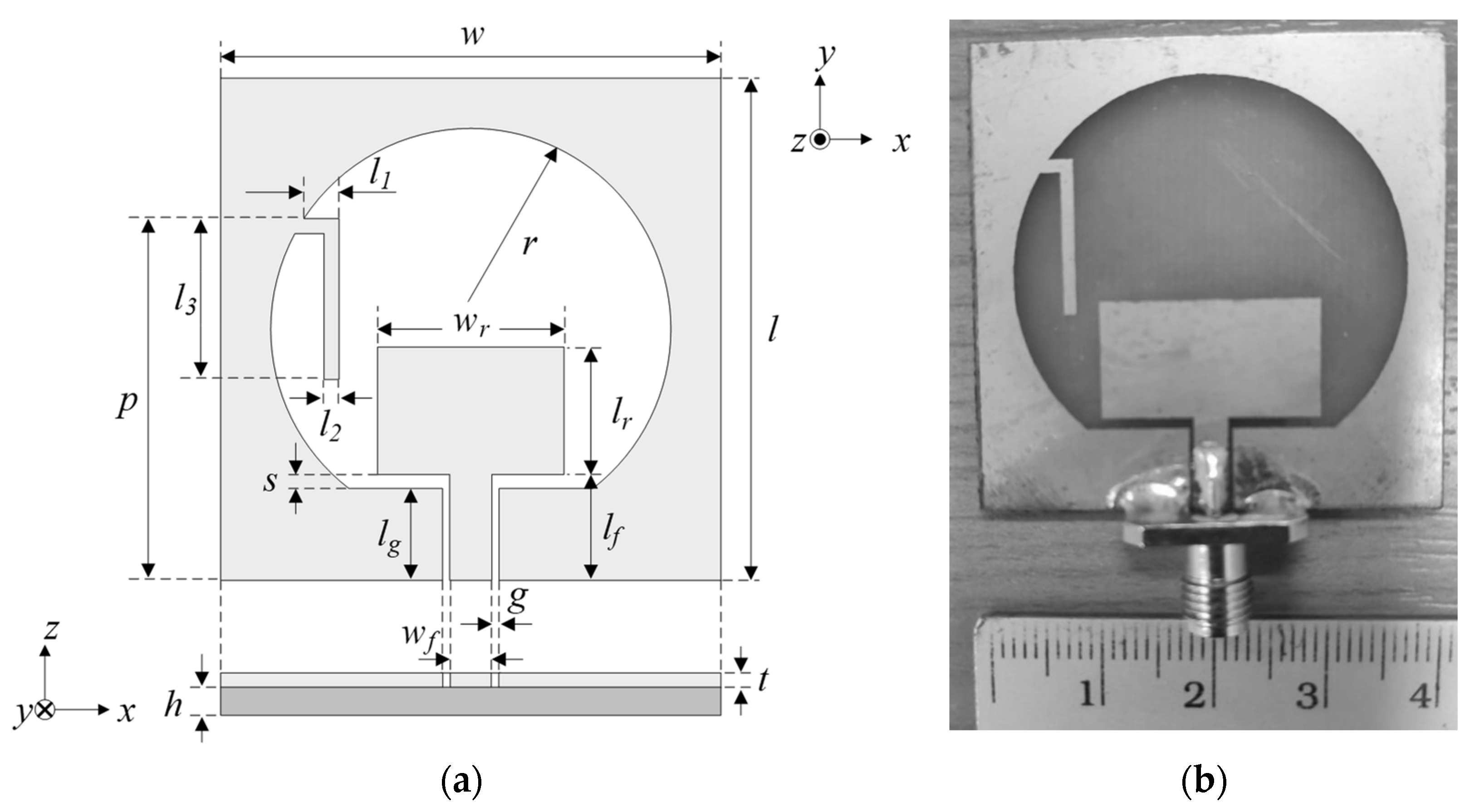
2. Structure of the Tri-Band Antenna
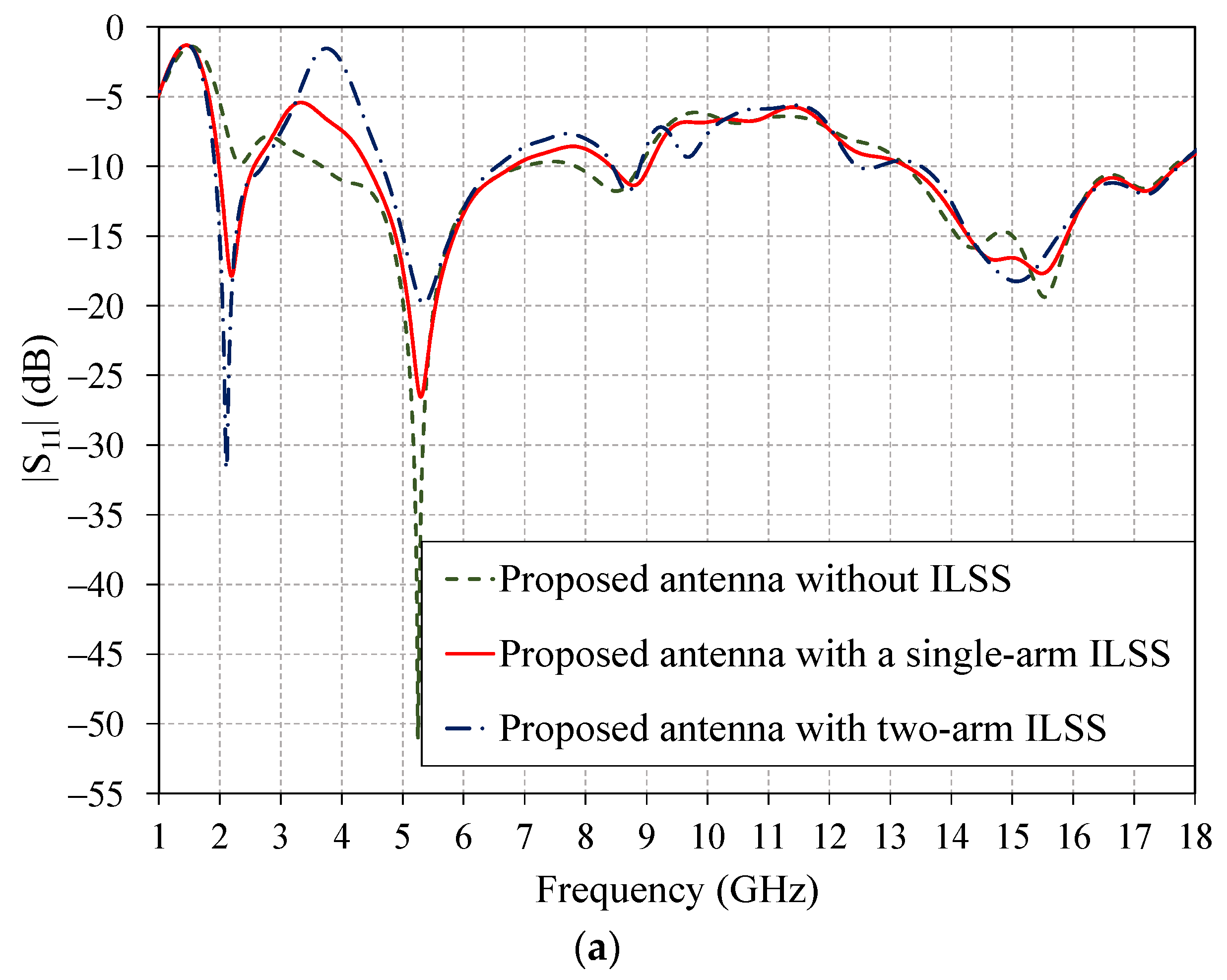
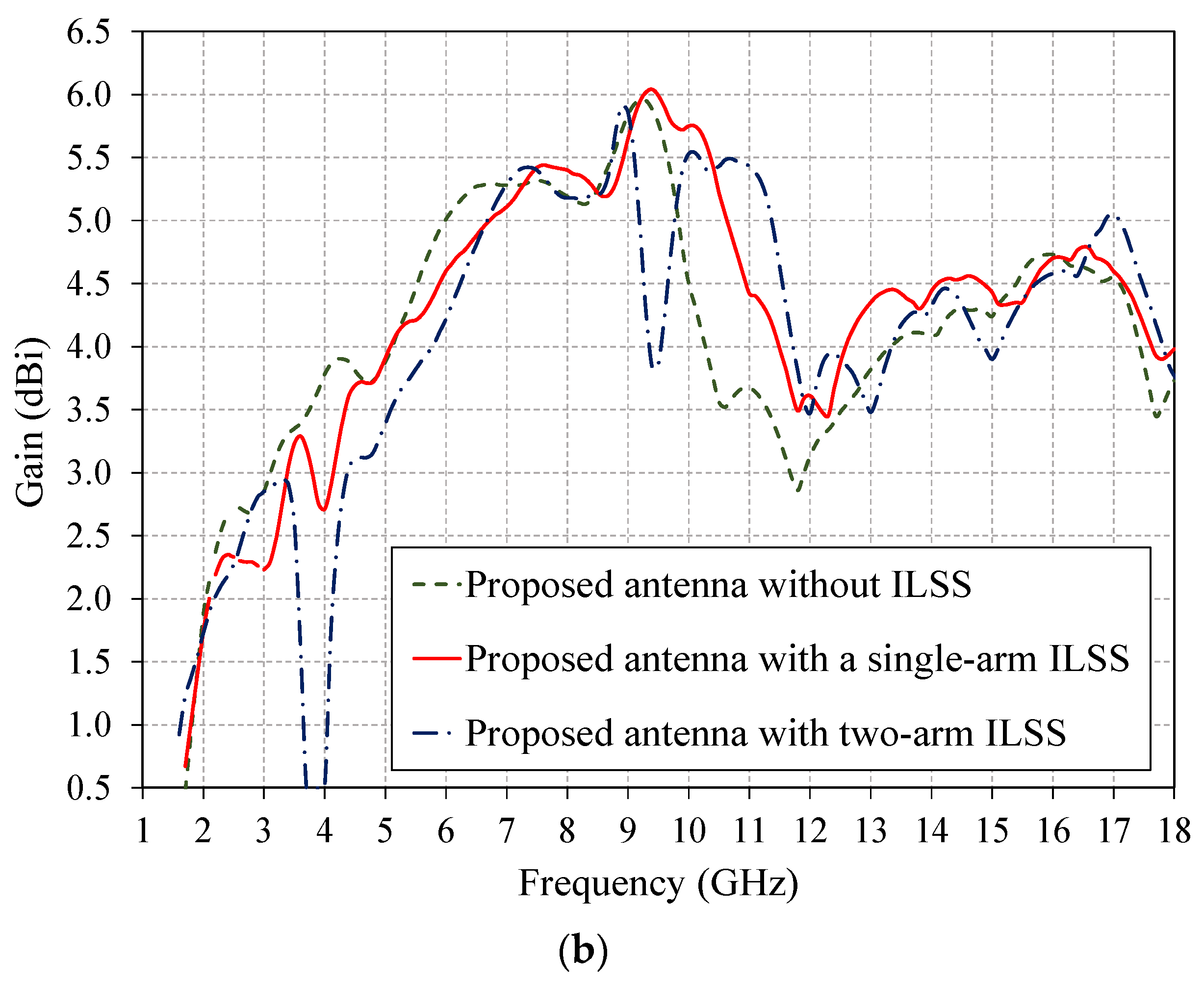
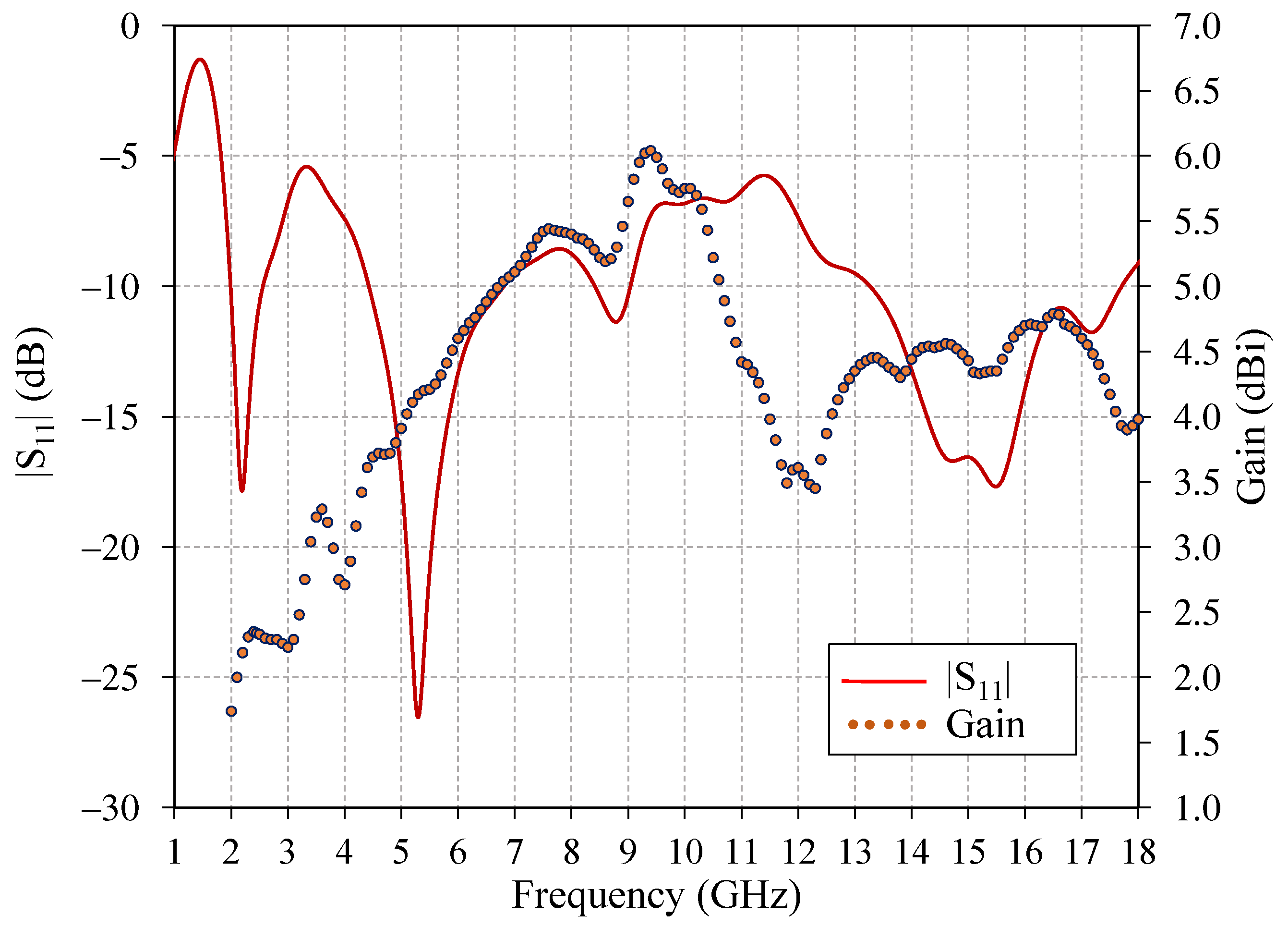
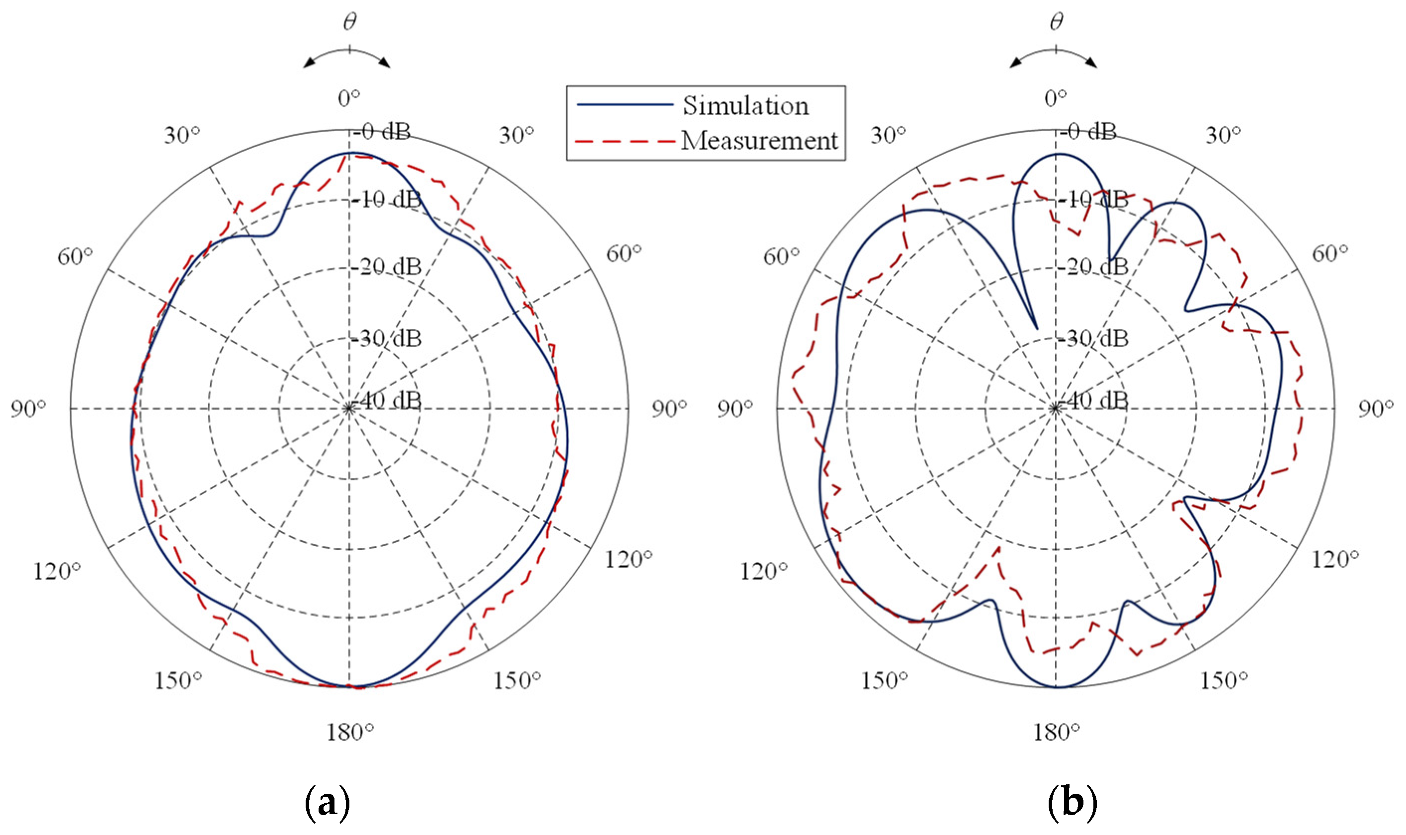
3. Simulation and Measurement Results
4. Conclusions
Author Contributions
Funding
Institutional Review Board Statement
Informed Consent Statement
Acknowledgments
Conflicts of Interest
References
- Hu, W.; Yin, Y.-Z.; Fei, P.; Yang, X. Compact Triband Square-Slot Antenna With Symmetrical L-Strips for WLAN/WiMAX Applications. IEEE Antennas Wirel. Propag. Lett. 2011, 10, 462–465. [Google Scholar] [CrossRef]
- Hongnara, T.; Mahattanajatuphat, C.; Akkaraekthalin, P.; Krairiksh, M. A multiband CPW-fed slot antenna with fractal stub and parasitic line. Radioengineering 2012, 21, 597–604. [Google Scholar]
- Lu, J.-H.; Huang, B.-J. Planar Compact Slot Antenna With Multi-Band Operation for IEEE 802.16m Application. IEEE Trans. Antennas Propag. 2012, 61, 1411–1414. [Google Scholar] [CrossRef]
- Hoang, T.V.; Park, H.C. Very simple 2.45/3.5/5.8 GHz triple-band circularly polarized printed monopole antenna with bandwidth enhancement. Electron. Lett. 2014, 50, 1792–1793. [Google Scholar] [CrossRef]
- Liu, H.; Li, R.; Pan, Y.; Quan, X.; Yang, L.; Zheng, L. A Multi-Broadband Planar Antenna for GSM/ UMTS/LTE and WLAN/WiMAX Handsets. IEEE Trans. Antennas Propag. 2014, 62, 2856–2860. [Google Scholar] [CrossRef]
- Pratyush, P.; Rani, G.V. A metamaterial-based tri-band antenna for WIMAX /WLAN application. Microw. Opt. Technol. Lett. 2016, 58, 558–561. [Google Scholar]
- Alqadami, A.S.M.; Jamlos, M.F.; Islam, I.; Soh, P.J.; Mamat, R.; Khairi, K.A.; Narbudowicz, A. Multi-Band Antenna Array Based on Double Negative Metamaterial for Multi Automotive Applications. Prog. Electromagn. Res. 2017, 159, 27–37. [Google Scholar] [CrossRef][Green Version]
- Trujillo-Flores, J.I.; Torrealba-Meléndez, R.; Muñoz-Pacheco, J.M.; Vásquez-Agustín, M.A.; Tamariz-Flores, E.I.; Colín-Beltrán, E.; López-López, M. CPW-Fed Transparent Antenna for Vehicle Communications. Appl. Sci. 2020, 10, 6001. [Google Scholar] [CrossRef]
- Moeikham, P.; Akkaraekthalin, P. A compact printed slot antenna with high out-of-band rejection for WLAN/WiMAX applications. Radioengineering 2016, 25, 672–679. [Google Scholar] [CrossRef]
- Januszkiewicz, L.; Barba, P.D.; Jopek, L.; Hausman, S. Many-objective automated optimization of a four-band antenna for multiband wireless sensor networks. Sensors 2018, 18, 3309. [Google Scholar] [CrossRef]
- Jha, K.R.; Bukhari, B.; Singh, C.; Mishra, G.; Sharma, S.K. Compact Planar Multistandard MIMO Antenna for IoT Applications. IEEE Trans. Antennas Propag. 2018, 66, 3327–3336. [Google Scholar] [CrossRef]
- Gangwar, A.K.; Alam, M.S. A miniaturized quad-band antenna with slotted patch. Int. J. Electron. Commun. 2019, 112, 152911. [Google Scholar] [CrossRef]
- Yang, M.; Sun, Y.; Li, F. A Compact Wideband Printed Antenna for 4G/5G/WLAN Wireless Applications. Int. J. Antennas Propag. 2019, 2019, 3209840. [Google Scholar] [CrossRef]
- Liu, T.; Sun, Y.; Li, J.; Yu, J.; Wang, K. CPW-fed compact multiband monopole antenna for WLAN/WiMAX/X-band application. PIER Lett. 2019, 87, 105–113. [Google Scholar] [CrossRef]
- Mohammad Saadh, A.W.; Poonkuzhali, R.R. A compact CPW fed multiband antenna for WLAN/INSAT/WPAN applications. Int. J. Electron. Commun. 2019, 109, 128–135. [Google Scholar] [CrossRef]
- Sreelakshmi, K.; Rao, G.S.; Kumar, M.N.V.S.S. A Compact Grounded Asymmetric Coplanar Strip-Fed Flexible Multiband Reconfigurable Antenna for Wireless Applications. IEEE Access 2020, 8, 194497–194507. [Google Scholar] [CrossRef]
- Camacho-Gomez, C.; Sanchez-Montero, R.; Martínez-Villanueva, D.; López-Espí, P.L.; Salcedo-Sanz, S. Design of a multi-band microstrip textile patch antenna for LTE and 5G services with the CRO-SL ensemble. Appl. Sci. 2020, 10, 1168. [Google Scholar] [CrossRef]
- Thanamalapong, W.; Phongcharoenpanich, C.; Lamultree, S. A tri-band antenna for 2.4/5 GHz WLAN and Ku-band applications. In Proceedings of the International Conference on Electrical Engineering/Electronics, Computer, Telecommunications and Information Technology (ECTI-CON), Phuket, Thailand, 24–27 June 2020; pp. 80–83. [Google Scholar]
- Surendran, A.; Aravind, B.; Ali, T.; Kumar, O.P.; Kumar, P.; Anguera, J. A dual-band modified franklin mm-wave antenna for 5G wireless applications. Appl. Sci. 2021, 11, 693. [Google Scholar] [CrossRef]
- Xu, P.; Yan, Z.H.; Wang, C. Multi-band modified fork-shaped monopole antenna with dual L-shaped parasitic plane. Electron. Lett. 2011, 47, 364–365. [Google Scholar] [CrossRef]
- Lu, G.; Yan, F.B.; Zhang, K. A Dual-Band High-Gain Subwavelength Cavity Antenna with Artificial Magnetic Conductor Metamaterial Microstructures. Micromachines 2022, 13, 58. [Google Scholar] [CrossRef]
- Chang, S.F.; Jeng, Y.H.; Chen, J.L. Dual-band step-impedance bandpass filter for multimode wireless LANs. IEE Electron. Lett. 2004, 40, 38–39. [Google Scholar] [CrossRef]
- Chen, H.D.; Chen, J.S.; Cheng, Y.T. Modified Inverted-L Monopole Antenna For 2.4/5 Ghz Dual-Band Operation. Electron. Lett. 2003, 39, 1567–1568. [Google Scholar] [CrossRef]
- AbuTarboush, H.F.; Nilavalan, R.; Budimir, D.; Al-Raweshidy, H.S. Double U-slots patch antenna for tri-band wireless systems. Int. J. RF Microw. Comput. Aided Eng. 2010, 20, 279–285. [Google Scholar] [CrossRef]
- Shang, Z.Q.; Xu, K.; Liu, Y. A Broadband Solar Radio Dynamic Spectrometer Working in the Millimeter-wave Band. Astrophys. J. Suppl. Ser. 2022, 258, 25. [Google Scholar] [CrossRef]
- Kosulvit, S.; Krairiksh, M.; Phongcharoenpanich, C.; Wakabayashi, T. A simple and cost-effective bidirectional antenna using a probe excited circular ring. IEICE Trans. Electron. 2001, 84, 443–450. [Google Scholar]
- Lamultree, S.; Phongcharoenpanich, C. Bidirectional Ultra-Wideband Antenna using Rectangular Ring Fed by Stepped Monopole. Prog. Electromagn. Res. 2008, 85, 227–242. [Google Scholar] [CrossRef][Green Version]
- Lamultree, S.; Phongcharoenpanich, C.; Kosulvit, S.; Krairiksh, M. Analysis of radiation characteristics of a probe-excited rectangular ring antenna by the dyadic Green’s function approach. PIER B 2009, 11, 79–101. [Google Scholar] [CrossRef]
- Lamultree, S.; Panthasa, R.; Phongcharoenpanich, C. Design and measurement of a probe-fed open-ended rectangular waveguide with four-stacked-coupling-aperture. Prz. Elektrotech. 2019, 95, 73–76. [Google Scholar] [CrossRef]
- Kumar, R.; Chaudhary, R.K. A new bidirectional wideband circularly polarized cylindrical dielectric resonator antenna using modified J-shaped ground plane for WiMAX/LTE applications. Radioengineering 2019, 28, 391–398. [Google Scholar] [CrossRef]
- CST Studio Suite. 3D EM Simulation and Analysis Software; Studio, C.P. CST Studio Suite; Simulia: Darmstadt, Germany, 2018. [Google Scholar]
- Balanis, C.A. Antenna Theory: Analysis and Design, 4th ed.; Wiley: Hoboken, NJ, USA, 2016. [Google Scholar]


| Symbol | Parameter | Physical Size (mm) |
|---|---|---|
| w | Width of the substrate | 40 |
| l | Length of the substrate | 40 |
| wr | Width of the rectangular patch | 19 |
| lr | Length of the rectangular patch | 10 |
| lf | Length of feeding strip | 8 |
| wf | Width of feeding strip | 3 |
| lg | Length of ground plane | 7 |
| g | Gap between feed line and ground plane | 0.4 |
| r | Radius of wide circular slot | 17 |
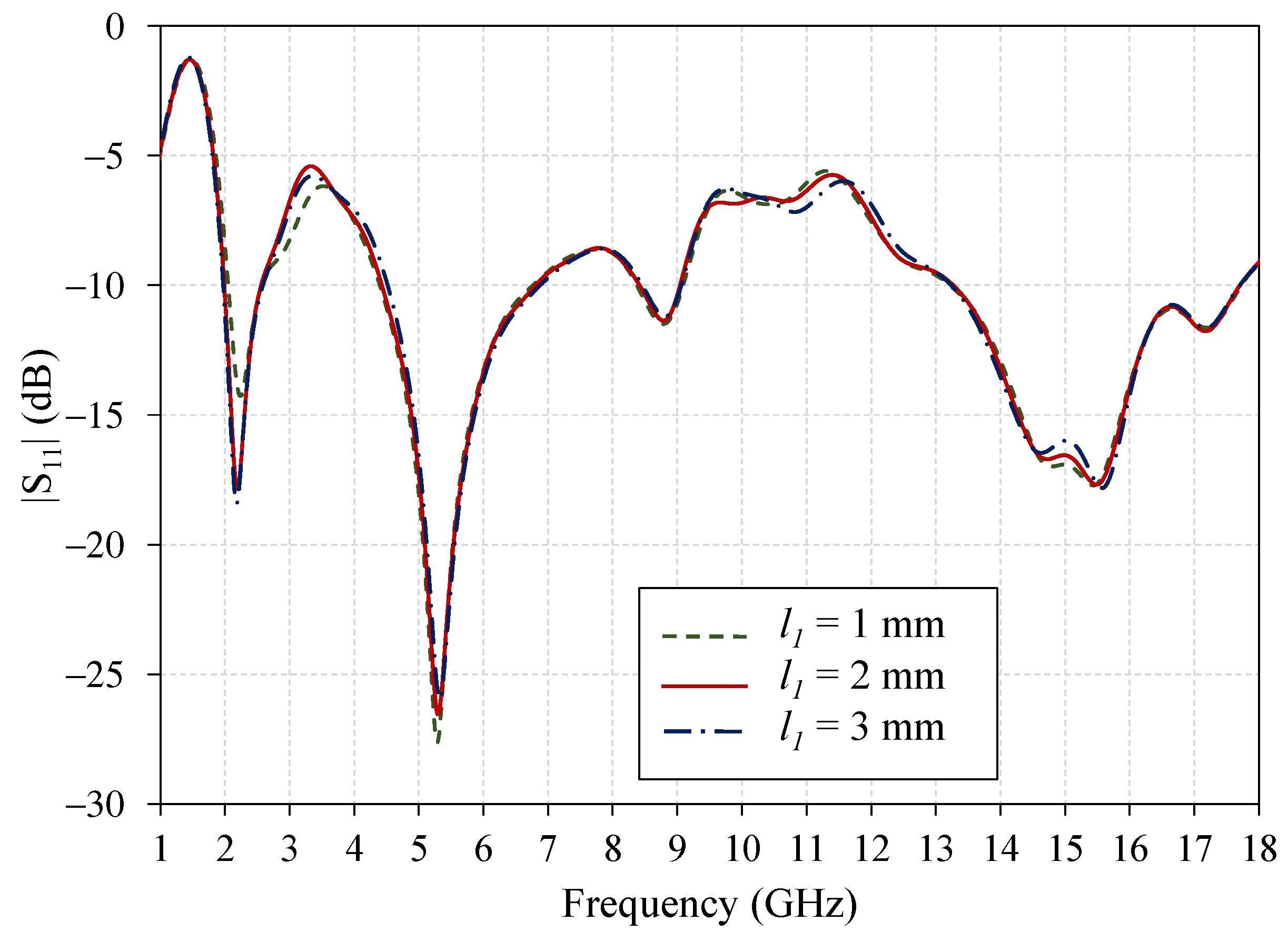
| l1 | Width of a single-arm ILSS | 2 |
| l2 | Thickness of a single-arm ILSS | 1 |
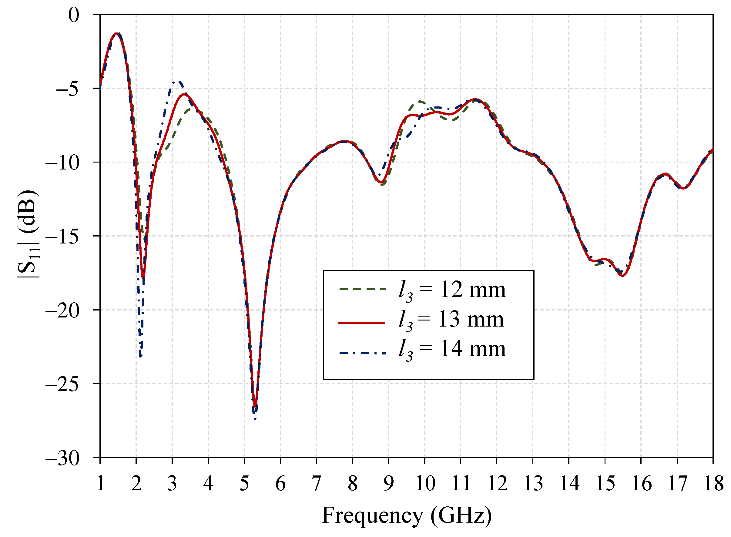
| l3 | Length of a single-arm ILSS | 13 |
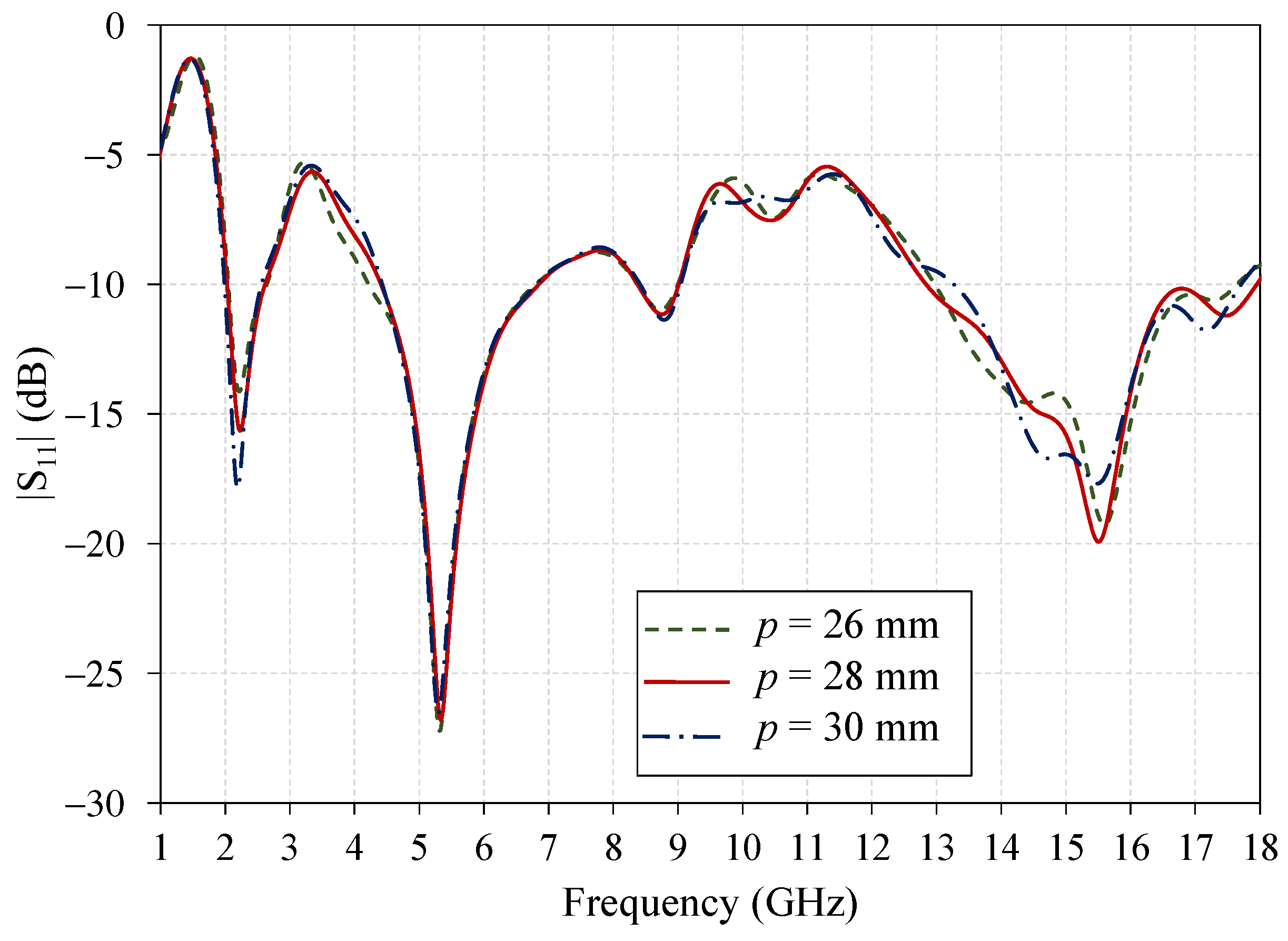
| p | Position of a single-arm ILSS | 30 |
| s | Spacing between the bottom of rectangular Patch and ground plane | 1 |
| h | Thickness of the substrate | 1.6 |
| t | Thickness of the copper layer | 0.003 |
| References | Fractional Bandwidth of |S11| | Pattern | Peak Gain (dBi) | Application | Overall Antenna Dimension (mm) | Structure |
|---|---|---|---|---|---|---|
| [1] | 2.34–2.82 GHz, 3.16–4.06 GHz, and 4.69–5.37 GHz | Omnidirectional | 3.06/3.13/3.10 | WLAN and WiMAX | 32 × 28 × 1 | FR-4 |
| [2] | 1.67–2.07 GHz, 2.35–4.23 GHz, and 4.65–5.43 GHz | Bi-directional | 3/3.5/1 | DCS, WiMAX, WLAN, and IMT | 48 × 50 × 0.8 | FR-4 |
| [5] | 790–1061 MHz, 1650–2775 MHz, and 3132–6382 MHz | Omnidirectional | 3/4/5 | GSM/UMTS/LTE and WLAN/WiMAX | 115 × 60 × 0.5 | TLY-5 |
| [6] | 2.5–2.78 GHz, 3.24–4 GHz, and 5.18–5.88 GHz | Omnidirectional | 1.65/2.59/3.94 | WLAN and WiMAX | 22 × 14 × 0.5 | F4B |
| [9] | 2.26–2.68 GHz, 3.28–4.09 GHz and 4.75–6.04 GHz | Omnidirectional | 1.67/2.75/5.5 | WLAN and WiMAX | 33 × 33 × 1.6 | FR-4 |
| [13] | 685–1012 MHz, 1596–2837 MHz, and 3288–3613 MHz | Omnidirectional | 1.4–2.5 | 4G/5G/WLAN | 60 × 120 × 1.5 | FR-4 |
| [14] | 2.24–2.85 GHz, 3.29–4.12 GHz, 5.13–6.24 GHz, and 6.58–8.57 GHz | Omnidirectional | 2.87/3.48/1.82/3.34 | WLAN/WiMAX/X-Band | 18 × 22 × 1 | FR-4 |
| [18] | 2.02–2.62 GHz, 5.08–6.27 GHz, and 11.97–18 GHz | Bidirectional | 2.27/4.02/5.05 | 2.4/5 GHz WLAN and Ku-band | 40 × 40 × 1.6 | FR-4 |
| [20] | 2.35–2.49 GHz, 3.27–3.8 GHz, and 4.65–5.89 GHz | Omnidirectional | 2.24/2.88/4.29 | WLAN and WiMAX | 34.5 × 18 × 1 | FR-4 |
| [23] | 2342–2548 MHz and 4877–5987 MHz | Omnidirectional | - | WLAN and HIPERLAN | 40 × 45 × 0.8 | FR-4 |
| Proposed | 2.10–2.70 GHz, 4.82–6.10 GHz, and 12.73–18 GHz | Bidirectional | 2.35/4.41/4.71 | 2.4/5 GHz WLAN and Ku-band | 40 × 40 × 1.6 | FR-4 |
Publisher’s Note: MDPI stays neutral with regard to jurisdictional claims in published maps and institutional affiliations. |
© 2022 by the authors. Licensee MDPI, Basel, Switzerland. This article is an open access article distributed under the terms and conditions of the Creative Commons Attribution (CC BY) license (https://creativecommons.org/licenses/by/4.0/).
Share and Cite
Lamultree, S.; Thanamalapong, W.; Dentri, S.; Phongcharoenpanich, C. Tri-Band Bidirectional Antenna for 2.4/5 GHz WLAN and Ku-Band Applications. Appl. Sci. 2022, 12, 5817. https://doi.org/10.3390/app12125817
Lamultree S, Thanamalapong W, Dentri S, Phongcharoenpanich C. Tri-Band Bidirectional Antenna for 2.4/5 GHz WLAN and Ku-Band Applications. Applied Sciences. 2022; 12(12):5817. https://doi.org/10.3390/app12125817
Chicago/Turabian StyleLamultree, Suthasinee, Wutthipong Thanamalapong, Sitthichai Dentri, and Chuwong Phongcharoenpanich. 2022. "Tri-Band Bidirectional Antenna for 2.4/5 GHz WLAN and Ku-Band Applications" Applied Sciences 12, no. 12: 5817. https://doi.org/10.3390/app12125817
APA StyleLamultree, S., Thanamalapong, W., Dentri, S., & Phongcharoenpanich, C. (2022). Tri-Band Bidirectional Antenna for 2.4/5 GHz WLAN and Ku-Band Applications. Applied Sciences, 12(12), 5817. https://doi.org/10.3390/app12125817