Article

Analysis of Contact Stress Distribution between Rolling Element and Variable Diameter Raceway of Cageless Bearing

Key Laboratory of Advanced Manufacturing and Intelligent Technology, Ministry of Education, Harbin University of Science and Technology, Harbin 150080, China
*
Author to whom correspondence should be addressed.
Appl. Sci. 2022, 12(12), 5764; https://doi.org/10.3390/app12125764
Submission received: 4 May 2022 / Revised: 25 May 2022 / Accepted: 1 June 2022 / Published: 7 June 2022
(This article belongs to the Section Mechanical Engineering)

Abstract

:
The change in contact state between the rolling elements and raceway of a cageless bearing with a variable diameter raceway affect the wear of the bearing, which leads to discrete motion failure of the rolling elements. For this purpose, the contact characteristics as contact form and contact stress between the rolling elements and raceway were determined. A numerical method is proposed to determine the three-dimensional contact stress of a cageless bearing. First, combined with the variable diameter raceway structure characteristics and the motion of rolling elements, the rolling elements and raceway contact stress model was established, and the influence factors of contact stress and the maximum stress distribution were determined. Based on the rolling contact theory, the relative position of the stick-slip region and the tangential stress distribution of the contact area were analyzed. The stress equations for the three-dimensional between rolling elements and variable diameter raceway were obtained by the principle of superposition, and the stress component characteristics of the contact area were numerically simulated. The results show that the main influencing factors of contact stress are: load, structure of variable diameter raceway, spindle speed, friction coefficient µ and the ratio of the stick region and the slip region k. Taking a cageless bearing as an example, the influence of the contact curvature Ri on the contact stress is smaller than that of ri. Increasing ri to make it larger than 1.5 mm and controlling the speed to be lower than 13,950 r/min, the maximum stress appears in the conventional raceway, which is beneficial to alleviate the failure of the variable diameter raceway. There are a slip region and a stick region in the contact area, reducing the friction coefficient µ and increasing the stick-slip coefficient k appropriately can ensure the discrete movement of the rolling elements and reduce the wear of the variable diameter raceway. The error of the stress distribution model is less than 15%, which can predict and characterize the contact stress distribution between the rolling elements and the variable diameter raceway. The theoretical guidance for the development and application of cageless bearings is provided.

1. Introduction

With the increasing application of high-speed equipment such as control systems for rocket engines and fans, the cageless bearing is used as the protective bearing of the electromagnetic bearing rotor system, the discrete performance of rolling elements is the premise to ensure the smooth operation of rotor [1,2]. The design of the local variable diameter raceway in the outer ring of bearing is a method to realize the discretization of rolling elements [3]. Considering the particularity of the local variable diameter raceway structure, when the rolling elements pass through the variable diameter raceway, the contact characteristics between the rolling elements and the bearing raceway change. To determine the influence of the contact characteristics between the rolling elements and the raceway on the discrete effect of the variable diameter raceway, it is necessary to analyze the contact state and contact stress between the rolling elements and the raceway. It is urgent to determine the three-dimensional contact stress distribution and the influencing factors of the contact characteristics of the discrete motion of the rolling elements, and optimize the design of the cageless bearing structure and provide suitable application conditions.
For research on the contact stress characteristics between the bearing rolling element and the raceway, Stribick et al. [4] combined with the classical Hertz theory to study the bearing contact characteristics, which ignored the friction in the contact area in the research process. Palmgren et al. [5] simplified the contact problem of the ball bearing and provided an ideal numerical model for the stress analysis in the static stage. Harris [6] considered the dynamic contact stress calculation model of the load, local deformation and rolling element motion state. In recent years, in order to improve the research on the contact stress of rolling bearing, researchers [7,8,9] have studied the existence of radial clearance and the influence of the shape of rolling elements on the contact stress, and suggest that having radial negative clearance minimizes the mutation of maximum contact stress, which provides the guidance for the design of a bearing raceway. Zhai et al. [10] suggested the calculation model of the maximum stress of rolling element and raceway under different operating speeds, and provided a basis for the setting of the bearing limit speed according to the influence of centrifugal force on the maximum stress of rolling elements and raceways at high speeds. Pandiyarajan et al. [11] proposed the contact stress distribution model of bearing parts under variable working conditions, and determined the influence of contact load and rotating speed on the variation law of maximum stress. Mehmet Bozca [12] developed a numerical model to calculate the maximum contact stress according to the geometric parameters of the bearing. The model was taken to provide the raceway contact radius with the static bearing capacity based on the maximum contact stress as the objective function. However, the study of bearing contact stress not only considered the distribution of macro maximum contact stress by influencing factors such as speed, load and bearing structure, etc., but also the microscopic stress distribution in the contact area also affects the contact characteristics of the rolling elements and raceway. The stress distribution and composition in the contact area not only inform the sliding between the rolling element and the raceway, but also have important significance for the prediction of bearing wear and life.
Carter [13] proposed a three-dimensional stress distribution theory in the elastic half-space of rolling contact based on the Hertzian theory of two-dimensional contact stress analysis. Reuss M et al. [14] investigated a method for determining the stick-slip boundary in the contact area based on the geometry of linear bearings. The method can determine the influencing factors of the contact friction between the rolling element and the raceway. Sen Gupta [15] generalized that there are both sticking and slipping areas in the contact area between the ball and the inner raceway of an angular contact ball bearing. The relationship between the rolling element motion and frictional traction in the sliding-adhesion zone is solved numerically. The interaction model between the contact pressure and shear stress in the slip region was carried out by Irina Gory et al. [16] using Coulomb’s law to explore the three-dimensional contact problem of elastic rolling elements; the relationship between the surface tensile stress and the friction coefficient was determined. Chen et al. [17] presented a surface rolling contact algorithm to investigate the use of the creep phenomenon caused by the relative displacement between the wheel and the rail. It was found that the coupling effect of the normal and tangential stress produces a tangential force with a regular distribution, which changes the shape and size of the contact spot. Johnson and Shcherbakov et al. [18,19] micro-differentiated the contact area through the superposition method and found the influence between tangential stress and normal stress. The method improved the accuracy of stress solution. Song et al. [20] deduced the contact ellipse truncation method to solve the maximum contact stress distribution model between the rolling element and the raceway. Toumi et al. [21] based on the “strip method”, discussed the relationship between compressive stress and shear stress in the contact area under cyclic load, and determined the relationship between shear stress distribution and friction coefficient. Lee et al. [22] theoretically investigated the stress distribution profile characteristics of the static contact area, and determined the relationship between the tangential frictional traction force of the rolling element, the raceway and the contact stress. The calculation amount of the numerical model is huge, the research on contact stress distribution using finite element technology and experiments has gradually developed in recent years. Lostado R et al. [23] developed a finite element stress distribution model for roller bearings, and obtained the distribution law and influencing factors of roller contact stress. Kania L. et al. [24] analyzed the influence of different structural forms on the stress distribution performance of slewing plate bearings through the finite element analysis method. However, due to various simplifications of the finite element model, the calculation of the contact stress distribution has certain limitations. The effects of load and rotating speed on the distribution characteristics of bearing contact stress are studied by strain equivalent experiment in references [25,26,27].
The above research on contact stress is aimed at standard bearings. These studies provide ideas and methods for establishing the contact stress distribution model. With the development of the machinery industry, the demand of non-standard bearings is gradually increasing [28]. The contact characteristics of non-standard bearings affect the mechanics and life of bearings. Hence, the research on the contact characteristics between the rolling element and raceway of non-standard bearings has gradually become a topic of interest. With the change in raceway structure, the contact point position, contact area, and contact characteristics of the rolling element and raceway also change [29]. The literatures [30,31] mainly deduced the influence of high and low point distribution of the raceway contour of the three lobe wave non-circular raceway bearing on contact load distribution characteristics. Zhang et al. [32] proposed the shape of the raceway as a variable and determined the radius ratio of the rolling element to the raceway to design the non-standard bearing structure with the maximum contact stress as the objective function using the Hertz theory. Wang [33] simplified the assumption of straightness of contact curvature of the elliptical raceway ball bearing and analyzed the influence of maximum contact stress of the raceway and elliptical curvature. Arendra et al. [34] considered different radial clearance values caused by the elliptical raceway, and analyzed the calculation error of the maximum contact stress between the elliptical raceway and rolling body with different macro geometry through the finite element method. Kim et al. [35] took the load distribution as the research object for the design of non-standard bearings, and determined the maximum contact stress model between the rolling element and the inner and outer rings from the perspective of isostress. Niu et al. [36] considered the contact stress law by studying the contact state of the four contact points and the distribution of the load in the contact area, which combined the change in the contact point between the rolling element and the raceway for the asymmetric four-point contact ball bearing. The research on the contact stress of the variable curvature raceway mostly focuses on the determination and influencing factors of the maximum contact stress, but there is little information on the three-dimensional stress distribution in the micro contact area.
Combining the characteristics of raceway structure and contact state changes when the rolling elements pass through the variable diameter raceway, this study proposes a three-dimensional contact stress calculation method between the rolling element and the raceway of a cageless ball bearing based on the rolling contact theory. This method macroscopically analyzes the influence of variable diameter raceway structure and different working conditions on the contact stress of cageless bearing. The narrow-band method was used to calculate stress components, and the three-dimensional contact stress numerical model in the contact area was established. This study determines the analytical solution of stress and reveals the characteristics of stress components in the contact area, and obtains the action relationship between the factors affecting the sudden change in stress. Finally, strain experiments were used to verify the validity of the stress model. This provides feasible theoretical guidance for the design and application of cageless bearing with a local variable diameter raceway, provides ideas for optimizing the structure to improve the maximum stress concentration, and ensures the discrete effect of the variable diameter raceway.
Our study mainly provides the following contributions:
First, the macroscopic contact stress distribution model was established with the raceway structure as a parameter, which provides a wide applicability for the study of raceway contact stress of non-standard bearings. The composition and distribution model of the microscopic three-dimensional stress in the contact area was established, which fills the gap in the research on the contact characteristics of non-standard bearings. Then, the narrow-band method was used to calculate each stress component of the three-dimensional stress distribution in the contact area, and determines the analytical solution of the stress component. Next, the dimensionless numerical solution of the stress component was carried out to provide an accurate law of stress distribution. Finally, through experimental comparative analysis, it was verified that our model and method are instructive in the contact stress distribution between the rolling element and the variable diameter raceway of the cageless bearing.

2. Motion and Contact State of the Rolling Element

The rolling elements of cageless bearing are in contact with each other during operation. The literature [37] proposed to design a variable diameter raceway structure in the outer ring raceway of the bearing. As shown in Figure 1, when rolling elements pass through the variable diameter raceway, the discrete effect is achieved. Assuming that the bearing outer ring is fixed, the inner ring rotates at an angular speed ωi, the radial load is applied, and the axial preload is zero. The inertial coordinate system (OiXiYiZi) is fixed at the rotating axis center of the outer ring. A variable diameter raceway is located in the load area of the bearing outer ring in a symmetrical structure. The design of the variable diameter raceway is related to the number of rolling elements and the diameter of the inner and outer ring raceways of the bearing. The variable diameter raceway structure parameters are expressed as θ1 and θ2. The axial span angle θ2 increases first and then decreases with the increase in the circumferential span angle θ1. The starting position of the variable diameter raceway forms an included angle θ1/2 with the negative direction of the Zi-axis. The circumferential span angle θ1 and axial span angle θ2 correspond to the range of 6 arcsin r o d i sin θ 2 2 θ 1 2 arcsin R 1 d i + d o and θ 2 < 2 arcsin d o θ 1 π 2 × 360 o r o , respectively. The radius of curvature of the variable diameter raceway in the YiOiZi plane is Ri, in the plane parallel to the XiOiZi plane, the radius of curvature is ri. The motion coordinate system of the rolling element mass center ObXbYbZb is established. The Xb-axis coincides with the rolling element rotation axis. The Zb-axis points to the rotation center of bearing.
Under the action of radial load Fr and centrifugal force, the rolling elements rotate around the Xb-axis while revolving circumferentially along the variable diameter raceway, the rolling elements maintain contact with the variable diameter. The normal force between the rolling element and the variable diameter raceway is Qi, the direction of Qi passes through the rolling element spherical center and is perpendicular to the contact area.
The contact surface is generated between the rolling elements and the variable diameter raceway under the radial load and is considered to be an ellipse based on the Hertz theory. The contact area is exaggerated in Figure 1, and its actual dimensions in engineering practice are quite small, based on which the contact coordinate system oxyz′ is established. The equivalent contact radius of curvature Ri and ri are related to the structure of the variable diameter raceway. As the position angle φi is different, the curvature radius Ri changes from the outer ring groove bottom radius to the radius of the variable diameter raceway transition region, and then to the inner gyration radius of the contact section (YiOiZi plane). ri changes from the curvature radius of the raceway groove to the radius of the variable diameter raceway transition region. When the rolling elements pass through the variable diameter raceway, combined with the discrete principle, the normal variable load Qi on the contact area varies with the angle of the rolling element at different positions of the variable diameter raceway. The variable diameter raceway is prone to generate alternating stress under the effect of the alternating load. The alternating stress leads to the wear of the variable diameter raceway, which changes the shape and size of the variable diameter raceway. The variable diameter raceway cannot achieve the effect of dispersion between rolling elements, hence, it is based on the analysis of stress characteristics when the rolling elements pass through the variable diameter raceway. The variable diameter raceway structure is optimized to ensure the effectiveness of the discrete movement of the rolling elements.

3. Analysis of Contact Stress Distribution between Rolling Element and Variable Diameter Raceway

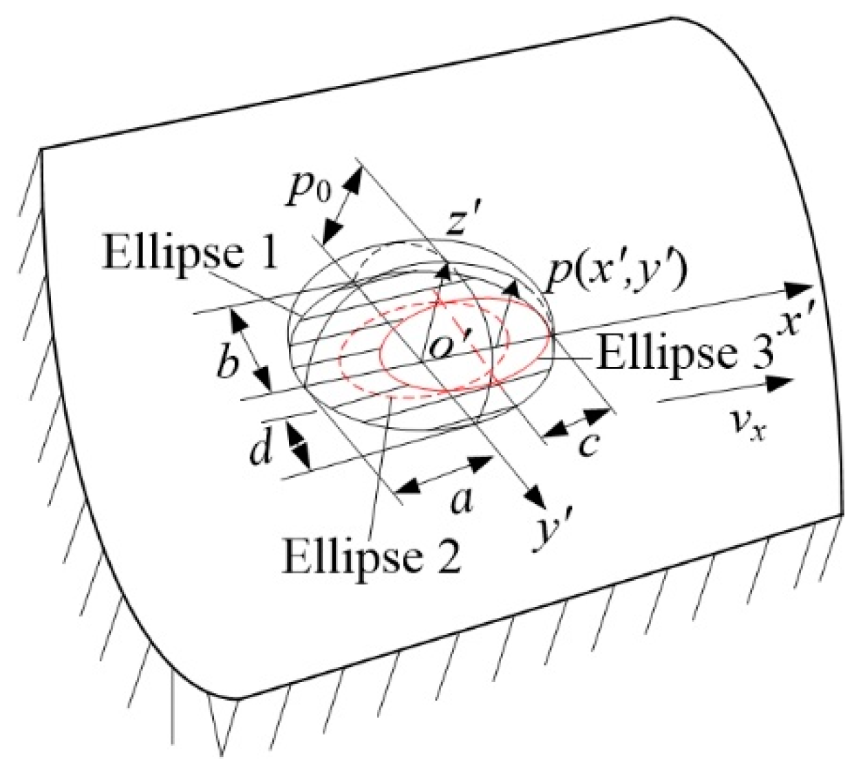
Based on the rolling contact theory, a three-dimensional tangential stress distribution model is obtained under the combined effect of the variable diameter raceway structure and load conditions at the rolling contact area. In rolling contact between the rolling elements and variable diameter raceway, the contact area is under compression. A slight deformation occurs in the contact area (x′–y′ plane), where o’ is the initial contact point, the elliptical contact area is defined, as shown in Figure 2.
The x′-axis is the direction of motion, and the contact normal load is the direction of the z′-axis. a and b denote the minor and major semi-axes of the ellipse, respectively. Semi-axis a is along the x′-axis, and semi-axis b is along the y′-axis. According to the Hertz contact theory, the equation of the contact deformation ellipse boundary between the rolling element and the variable diameter raceway can be expressed as:
x 2 a 2 + y 2 b 2 = 1
The distribution of the normal stress p (x′, y′) in the contact area can be expressed as:
p x , y = p 0 1 x 2 a 2 y 2 b 2
where p0 is maximum surface stress at the center point o′ of contact area, and is the maximum contact stress in the ellipse contact area, p0 can be obtained as:
p 0 = 3 Q i 2 π a b = 6 Q E * 2 π 3 R 2 1 3
where the normal variable load of the rolling element enters and exits at both ends of the variable diameter raceway is: Q i = d i + d o m ω c j 2 cot γ / 2 m R 1 ω ˙ c j .The variable diameter raceway is: Q i = R 1 + d i / 2 m ω c j 2 + G sin mod φ i , 2 π 2 cos α . do is outer raceway diameter, do′ is diameter of the contact trajectory within variable diameter raceway. E* is the equivalent elastic modulus, which is calculated by Equation (4):
1 E = 1 υ 1 2 E 1 + 1 υ 2 2 E 2
where υ 1 , υ 2 , E 1 and E 2 are the Poisson’s ratio, elastic modulus of the materials of the rolling elements and the variable diameter raceway. R is the equivalent radius of curvature at the contact point in Equation (3). According to the geometrical characteristics of the variable diameter raceway, the equivalent radius can be obtained from Equation (5):
R * = ( R R ) 1 2 = R 1 R i R 1 r i R 1 + R i R 1 + r i 1 2
where RI and RII are the relative radii of the curvatures at the contact point. R 1 and R 1 are the main radii of the curvatures of the rolling element and the variable diameter raceway at the initial contact point, respectively (as shown in Figure 1). R1 is the radius of the rolling element. When the contact area is in the transition region of both ends of the variable diameter raceway, Ri = ro; ri = r. When the contact area is in the non-transition region of both ends of the variable diameter raceway, Ri = r; r i = d o 2 cos θ 2 2 . r is the transition radius of the variable diameter raceway. do′ is the diameter of the circle formed by the contact point, d o = d o 2 R 1 R 1 2 r o sin θ 2 2 2 0.5 . a and b are calculated by Equations (3)–(5):
a = a * 3 Q i 2 E * ρ 1 / 3   ,   b = b * 3 Q i 2 E * ρ 1 / 3
The contact load between the rolling elements and the variable diameter raceway is an alternating load. Friction and sliding occur with the change in the radius of curvature, which makes the contact stress of variable diameter raceway alternating stress. There will be a spatially varying shear stress field in the contact area due to the alternating stress. From a macroscopic point of view, the judgment of the rolling state between the rolling element and the variable diameter raceway is directly affected by the shear stress field. From a microscopic point of view, the impact failure in the contact area is due to abrupt changes within the spatial stress field. To ensure that slipping and stress concentration do not occur when the rolling elements pass through the variable diameter raceway, it is necessary to analyze the contact state and stress distribution in the contact area.
When the rolling elements enter the variable diameter raceway, the normal force in the contact area is only provided by the centrifugal force and the gravity of the rolling element, the tangential stress at the boundary of the contact area tends to infinity. Hence, the contact condition cannot be satisfied and results in relative slipping. In the transition region, the normal load is provided by the radial load and the centrifugal force of the rolling elements of the bearing. As the position angle of the rolling element gradually increases, the tangential friction force gradually decreases. Therefore, under the combined action of the tangential stress and the normal stress, the stick-slip phenomenon occurs in the contact area when the rolling elements pass through the variable diameter raceway.
When stick-slip occurs between the rolling elements and the variable diameter raceway, one side of the contact area along the rolling direction is compressed and the other side is stretched. The contact area moves along the direction of the tangential stress, the offset distances of all the points are equal. The shape of the contact area is shown in Figure 2. The semi-axes c and d of the stick region (ellipse 2) coincide with the x′ and y′-axis. The stick region is offset along the rolling body direction under the action of tangential stress, the shape and boundary of the contact area remains unchanged in ellipse three during the displacement process. The front part of the contact area is the stick region, the rear part is the slip region, and the slipping offset distance is s.
According to Carter’s rolling contact theory, the distribution of the tangential stress in the three-dimensional rolling contact area is accomplished by the superposition principle, it is calculated as follows:
p = p x , y slip   region p x , y + q x , y stick   region
where p x , y and p x , y ± q x , y denote the distributions of the tangential stress in the slip and stick region, respectively. p x , y = 3 μ Q 2 π a b 1 x 2 a 2 y 2 b 2 1 / 2 2 c a < x 1 < a , q x , y = 3 c μ Q 2 π a 2 b 1 x + s c 2 y d 2 1 / 2 a x 1 2 c a ) . A negative sign indicates that the tangential stress is in the opposite direction of the motion.
Since the width of the ellipse contact area changes with the y-axis, a is much smaller than b. Contact stress p1 is very small near x1 = a. The elliptical contact area was divided into numerous narrow bands, and the corresponding contact width is 2x, the normal stress in the contact area can be calculated as: p 1 = 3 Q 2 π a b 1 x 1 a 2 y 1 b 2 .
The three-dimensional contact stresses of each narrow band under a normal stress p1 can thus be expressed as:
σ x p = P 1 a m 1 + z 2 + n 2 m 2 + n 2 2 z σ z p = P 1 a m 1 z 2 + n 2 m 2 + n 2 τ x z p = P 1 a n m 2 z 2 m 2 + n 2
where:
m = 1 2 a 2 1 y 2 b 2 x 2 + z 2 2 + 4 x 2 z 2 1 / 2 + 1 2 a 2 1 y 2 b 2 x 2 + z 2 n = 1 2 a 2 1 y 2 b 2 x 2 + z 2 2 + 4 x 2 z 2 1 / 2 1 2 a 2 1 y 2 b 2 x 2 + z 2
According to the relationship between the tangential stress and the normal stress of the sliping contact, it can be observed that the tangential stress distribution in the slip region is the same in the rolling contact and sliping states, but in opposite directions. The stress components induced by the tangential stress p′ (x, y) in the contact area can be expressed as follows:
σ x p = σ x p = μ p a n 2 z 2 m 2 m 2 + n 2 2 x σ z p = σ z p = μ p a n m 2 z 2 m 2 + n 2 τ x z p = τ x z p = μ p a m 1 + z 2 + n 2 m 2 + n 2 2 z
From Equation (6), the distribution of q′ (x, y) is only defined in the stick region, and is similar to that of p′ (x, y), satisfying a certain proportion relationship. The stress components due to q′ (x, y) can thus be expressed as:
σ x q = μ q c n 2 z 2 m 2 m 2 + n 2 2 x + s σ z q = μ q c n m 2 z 2 m 2 + n 2 τ x z q = = μ q c m 1 + z 2 + n 2 m 2 + n 2 2 z
where m′ and n′ as follows:
m = 1 2 c 2 1 y 2 d 2 x + s 2 + z 2 2 + 4 x + s 2 z 2 1 / 2 + 1 2 c 2 1 y 2 d 2 x + s 2 + z 2 n = 1 2 c 2 1 y 2 d 2 x + s 2 + z 2 2 + 4 x + s 2 z 2 1 / 2 1 2 c 2 1 y 2 d 2 x + s 2 + z 2
According to the results obtained by Johnson for a problem involving tangential stress, the total stress can be obtained by superposition of the stress components. The dimensionless analytic equations are here introduced to express the stress components in the contact area, using W = x/a; H =y/b; B = z/a. By the superposition of Equations (7)–(9), the three-dimensional stresses σx/p0; σz/p0; and τxz/p0 can be obtained as:
σ x p 0 = 1 1 H 2 [ Q B 2 + T 2 Q 2 + T 2 μ T B 2 Q 2 Q 2 + T 2 + Q + 2 μ T 2 ( B + μ W ) ] μ k 2 H 2 [ T ( 2 B 2 Q 2 Q 2 + T 2 ) k ( 1 + W k ) k 2 H 2 ] σ z p 0 = 1 1 H 2 [ Q Q B 2 + T 2 Q 2 + T 2 μ T B 2 Q 2 Q 2 + T 2 ] μ k 2 H 2 [ T Q 2 B 2 Q 2 + T 2 ] τ x z p 0 = 1 1 H 2 [ T Q 2 B 2 Q 2 + T 2 μ Q Q 2 + B 2 + 2 T 2 Q 2 + T 2 ] + μ k 2 H 2 [ Q B 2 + Q 2 + 2 T 2 Q 2 + T 2 2 B ]
where the parameter k is defined as distribution ratio of the stick region to the slip region, where k = c / a = d / b = 1 p / μ p x , y 1 / 3 .
Q 2 = m 2 a 2 = 1 2 1 H 2 W 2 + B 2 2 + 4 x 2 z 2 1 / 2 + 1 H 2 W 2 + B 2 2 T 2 = n 2 a 2 Q 2 = 1 2 1 H 2 k 2 W 2 + B 2 2 + 4 x + s 2 z 2 1 / 2 + 1 H 2 k 2 W 2 + B 2 2 T 2 = n 2 a 2
The total stress σp distribution in the contact area between the rolling element and the variable diameter raceway is obtained by linearly superimposing Equation (10) as:
σ p = σ p 1 + σ p + σ q
According to the above analysis, it can be obtained that the main influencing factors of the contact stress between the rolling elements and the variable diameter raceway are: normal load, the size of the contact curvature radius of the variable diameter raceway, the friction coefficient between the rolling element and the raceway, and the ratio of stick region and slip region.

4. Numerical Analysis of the Contact Characteristics

4.1. Numerical Analysis of Contact Stress

In order to analyze the stress distribution at different positions of the variable diameter raceway, combining the two factors of the variable diameter raceway structure and normal load, the variable diameter raceway structure in reference [37] was taken as an example. The variation range of its curvature radius Ri is 24.92 mm–25.7 mm. ri selects four sizes of 0.5 mm, 1.5 mm, 15 mm, and 150 mm. Other dimensions and structural parameters of bearings with local variable diameter raceway are shown in Table 1.
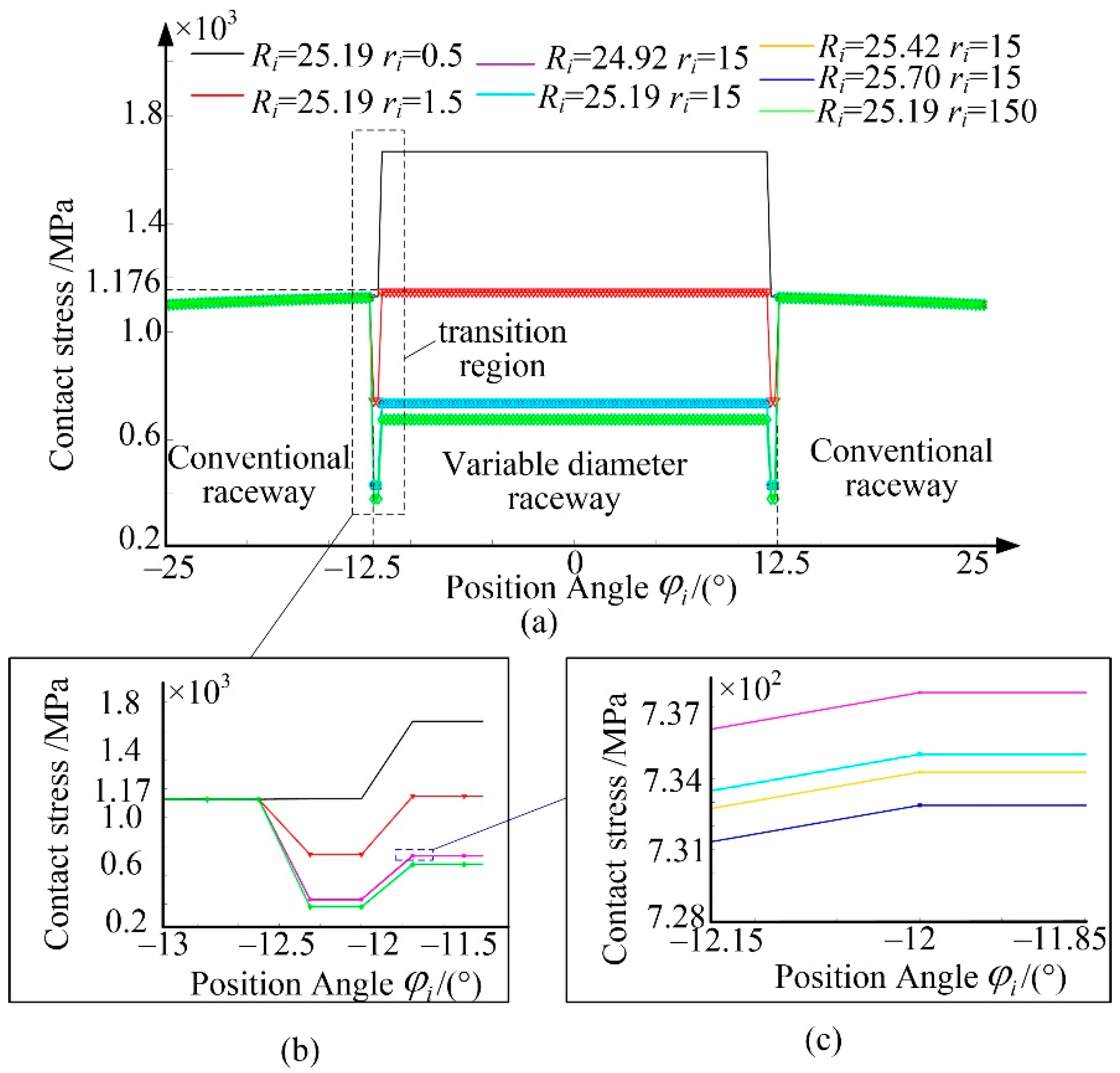
Combined with Table 1 and Equations (8)–(12), the influence of different variable diameter curvatures on contact stress was analyzed from a macro perspective, the contact stress at different positions of the raceway was obtained as shown in Figure 3.
Figure 3a shows that the rolling elements and the raceway are in different contact positions due to different position angles. The rolling elements pass through the conventional raceway, transition region and variable diameter raceway in turn. The contact stress and load are different due to the different radii of curvature of the raceway during this process. The contact stress between the rolling element and the outer ring increases as the position angle approaches the radial load action line in the conventional raceway, the trend is distributed to the regular sinusoidal curve. When φi = −12.5°, the maximum stress value of the conventional raceway is 1176 MPa. In the transition region of the variable diameter raceway, the contact stress is affected by curvatures Ri and ri of the variable diameter raceway. As ri increases, the contact stress gradually decreases. Moreover, as the rate of change in ri increases, the effect of ri on the contact stress tends to be stable (as shown in Figure 3b). The reason for this is that the contact form between the rolling element and the variable diameter raceway tends to be in contact with ball and plane when ri tends to infinity. When the load is constant the contact stress variation range is almost unchanged. Combined with the range of Ri, when the rolling element is in the variable diameter raceway, as Ri increases, the stress at different positions of the variable diameter raceway decreases (Figure 3c). When ri is larger than 1.5 mm, the contact stress in the variable diameter raceway is smaller than that in the conventional raceway. Maximum stress during operation is generated in the conventional raceway. When the rolling element enters the variable diameter raceway, the stress decreases first and recovers after exiting variable diameter raceway. When ri is less than 1.5 mm, the stress of the variable diameter raceway is larger than that of the conventional raceway, which indicates that the rolling elements are subject to a stress shock when entering the variable diameter raceway. When Ri = 25.19 mm, ri = 1.5 mm, the contact stress between the conventional raceway and the variable diameter raceway is equal. There is no stress mutation leading to impact and collision when the rolling elements are in motion. Ri has little influence on the distribution of contact stress, and ri has a greater effect of the distribution of contact stress because the range of Ri is very tiny.
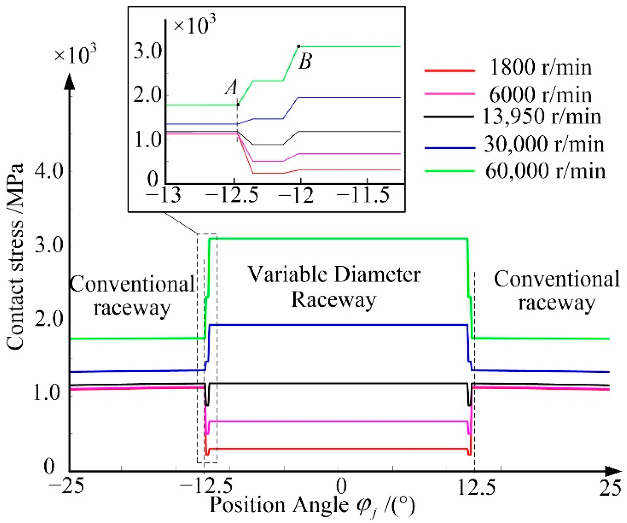
The factors affecting the stress of the variable diameter raceway are the contact curvature radius and the load acting on the contact area according to Equation (3). The change in bearing speed causes the change in centrifugal force and contact load. Combined with the geometric structure, the relationship between the speed and the angular contact stress at different positions is obtained as shown in Figure 4. The radius of curvature of the variable diameter raceway was selected as Ri = 25.19 mm, and ri = 1.5 mm according to the stress mutation during the movement process, the radial load was set as 500 N. Figure 4 illustrates that the contact stress between the rolling element and the outer ring increases gradually in the form of a regular sinusoidal curve as the position angle gradually decreases. The contact stress has a linear relationship in the variable diameter raceway; however, there is a tendency for abrupt stress change in the transition region due to load changes. With the increase in rotational speed, the contact stress increases gradually.
When the rotational speed is less than 13,950 r/min, the contact stress of the rolling elements in the variable diameter raceway is smaller than that of the conventional raceway. The reason is that main load source of the raceway at low rotational speed is the radial load. As the rotational speed increases, when the rotational speed is larger than 13,950 r/min, the contact stress of the rolling elements increases gradually. When the stress reaches the maximum, the rolling elements just reach the variable diameter raceway. This is because the large centrifugal force generated by the rolling elements at high speed becomes the main normal load. Combined with the variable diameter raceway structure and Equation (3), it can be observed that the smaller the equivalent contact radius is in the variable diameter raceway, the larger the contact stress is in the variable diameter raceway. Focusing on the stress change area, the A-B area in Figure 4 depicts the initial transition area of the variable diameter raceway. Since the radius of curvature ri in the transition region is relatively large, and is only affected by the centrifugal force of the rolling elements, the maximum stress of the raceway occurs at the point where the rolling elements enter and exit the variable diameter raceway. In order to reduce the influence of centrifugal force on the contact stress during the movement of the rolling elements, combined with the radial load, it is necessary to control the rotational speed below 13,950 r/min, to ensure that there is no obvious stress mutation during the operation.
According to the above analysis, it can be seen that in the process of rolling elements passing through the variable diameter raceway, the maximum stress on the variable diameter raceway is determined by the variable diameter raceway structure and the rotational speed. Therefore, the position of the maximum stress can be determined in different working conditions. Then the micro-contact characteristics generated at the maximum contact stress can be analyzed.

4.2. Numerical Analysis of Stress Distribution in Contact Area

From the analysis, it is observed that the stress state in the contact area affect the contact slipping and rolling states of the rolling element and the raceway. The friction coefficient µ and the ratio k of the stick region and the slip region are the main factors. The effects of different values of µ and k on the stress components are shown in Figure 5.
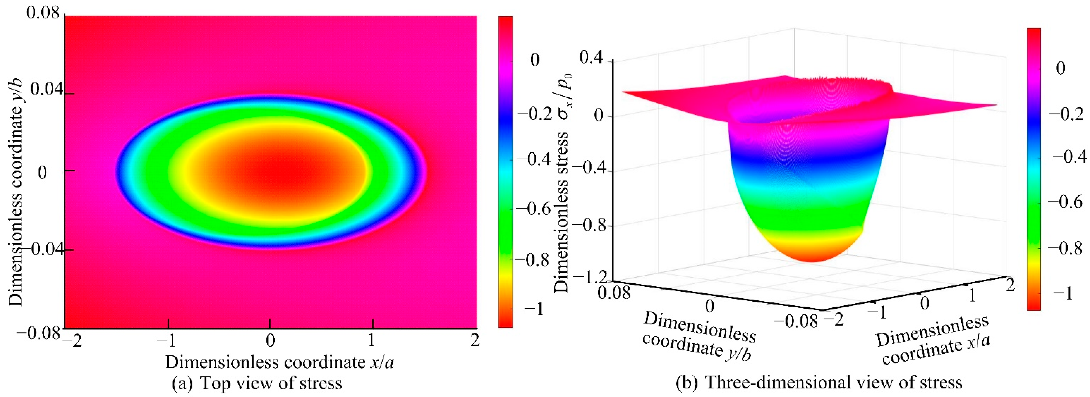
As shown in Figure 5a, the rolling elements roll in the negative direction of the x-axis, which offsets the stress of the stick region in the rolling direction. The normal stress is compressive in the rolling direction and tensile in the opposite direction and the amplitude of the compressive stress is larger than that of the tensile stress as shown in Figure 5b. The existence of tangential friction during the contact between the rolling element and the raceway causes the velocity difference of the relative movement of the contact area, which results in the creep phenomenon in the micro-contact area. The maximum compressive stress is shifted to the rolling direction, while the maximum tensile stress is at the trailing edge of the contact area. The stress mutation occurs at the junction of the stick region and the slip region of the adopted Carter theory. The non-continuous distribution of stress in the contact area leads to uneven stress on the material. In actual contact, there is a large stress gradient at the junction of the stick region and the slip region.
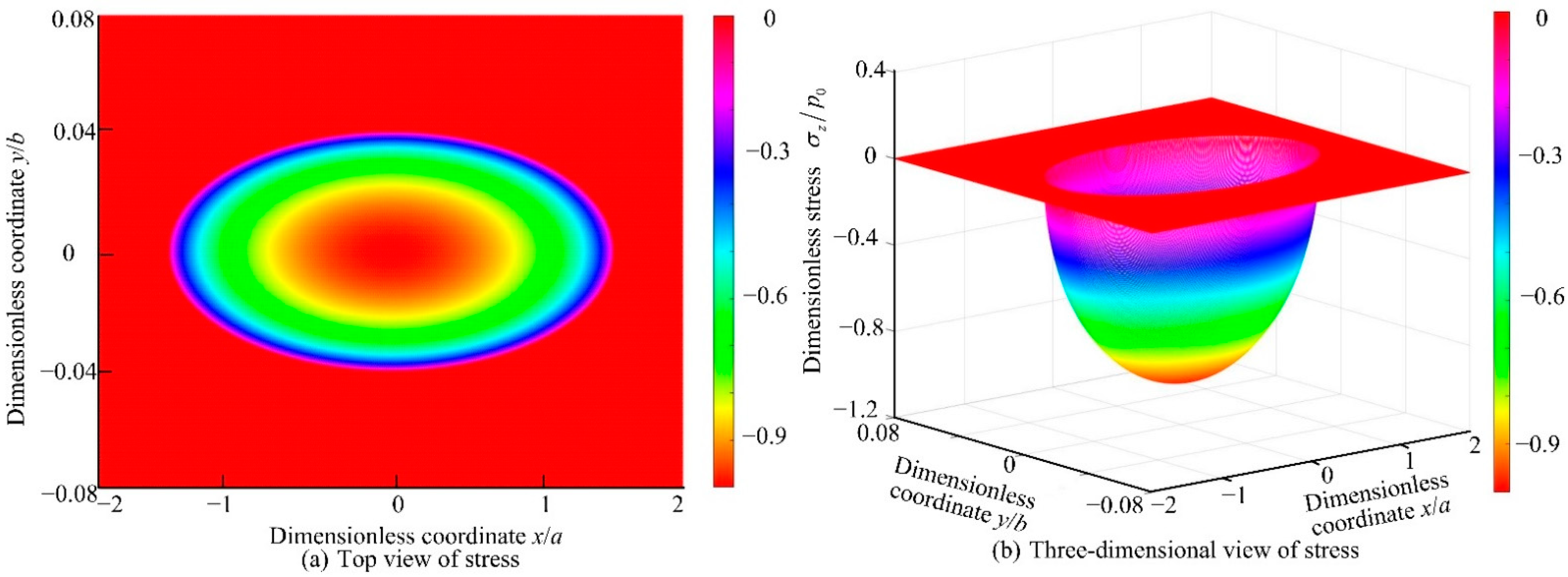
Figure 6 illustrates that the variation of σz/p0 in the contact area. The stress value reaches the maximum when x/a = 0, and it is distributed in a hemispherical shape in the contact area. There is no stress mutation in the normal direction. Normal stress has no effect on rolling and slipping in the contact area.
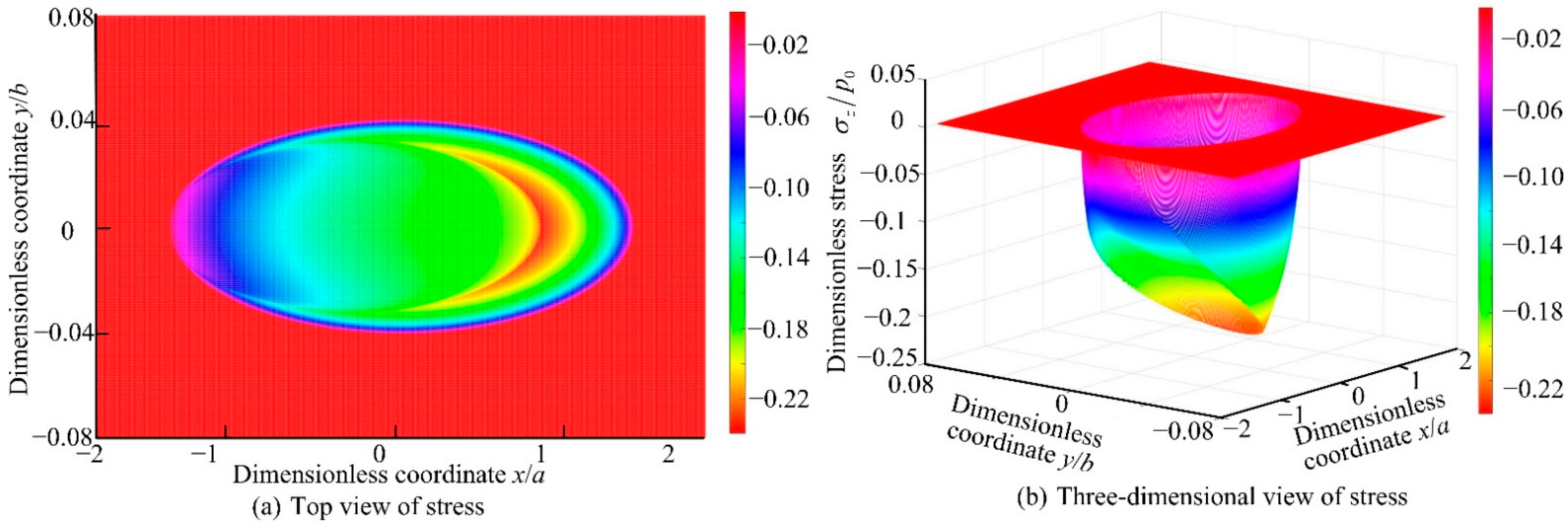
Figure 7 shows the variation of τxz/p0 for k = 0.8 and µ = 0.15. It can be clearly observed that in the slip region, the stress is larger. Stress mutation occurs at the junction of the stick region and the slip region, moreover, the maximum stress value appears in the tangential slipping direction.
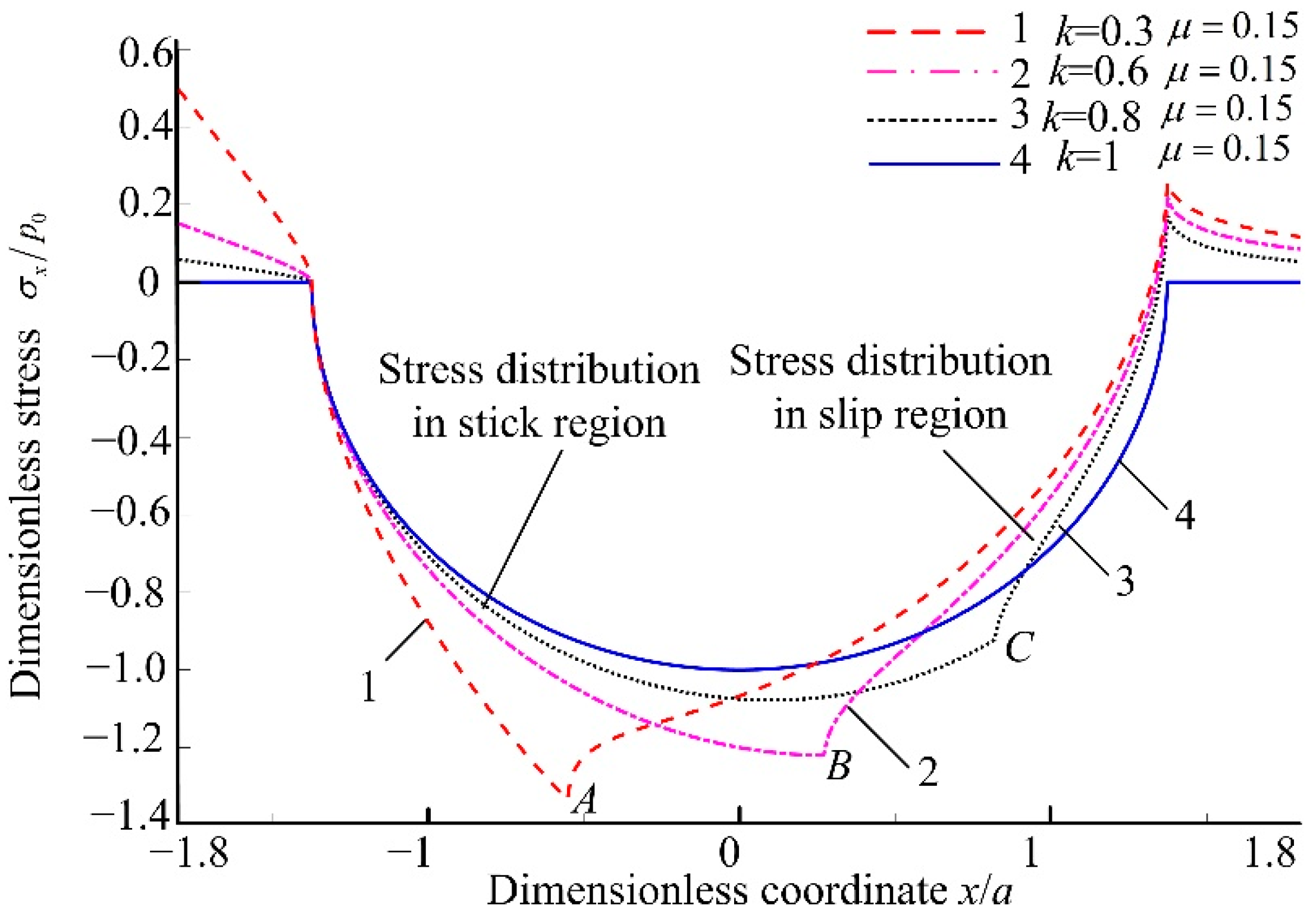
Figure 5, Figure 6 and Figure 7 show the maximum contact stress between the rolling element and the variable diameter raceway in the contact area, there is no stress mutation in the normal direction, and the tangential stress mutation is related to the existence of the slip region and the stick region. The tangential stress is related to the friction coefficient μ and the stick-slip coefficient k. Therefore, the influence of different friction coefficient μ and stick-slip coefficient k on the dimensionless tangential stress σx/p0, τxz/p0 is described below.
Figure 8 is the variation law of stress components σx/p0 for fixed values of µ = 0.15 and y/b = 0 and varying values of k. Points A, B, and C are the stress mutation points under different k. When k = 1, the whole contact area is a stick region, there is no slip phenomenon or stress mutation in the contact ellipse which is an ideal situation without slip. When k < 1, the smaller k is, the smaller the stick region is, and the location of the stress mutation is closer to the rolling direction of the rolling elements. Moreover the stress in the stick region increases with the decrease in k, and the compressive stress in the slip region increases with the k increases. The faster the tensile stress disappears with the increase in k. Comparing the values of points A, B, and C, which are −1.3, −1.2, and −1.0, respectively, it can be seen that the stress mutation is not proportional to the k; the larger k is, the larger the stress mutation value is; the larger the stress mutation rate is, the easier it is to fail at the contact point. When the friction coefficient µ is constant, the faster the rolling element moves, the larger the transmission force is. High speed causes k to decrease and the tangential force to increase. The contact area of the local slip region becomes larger and can lead to slip. Moreover, under the condition of a periodic load, the wear and fatigue are more likely to occur at the variable diameter raceway, resulting in the failure of variable diameter discrete action.
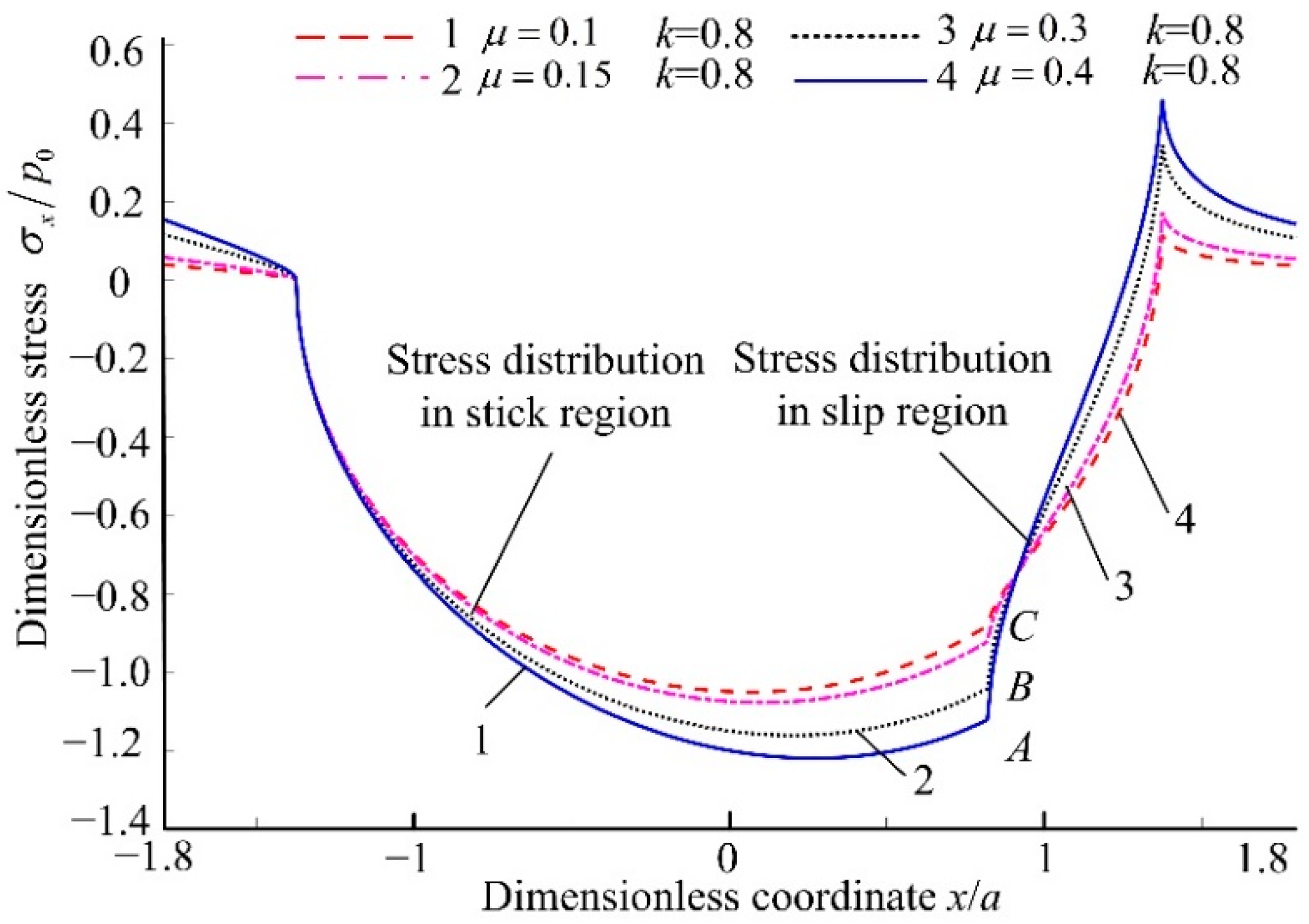
Figure 9 shows that the variation law of stress components σx/p0 for k is constant and there are varying values of µ. The results in Figure 9 show that the friction coefficient µ has a slight effect on the stress. The change in friction coefficient µ within the 0.1–0.4 range causes the change in dimensionless stress σx/p0 for no more than 18.07%, which in the stick region is not more than 20.1%, and in the slip region is not more than 18.05%. The tangential stress in the slip region is less than the tangential stress in the stick region. When the friction coefficient σx/p0 is larger, the relative difference between compressive stress and tensile stress is larger, which leads to the stress mutation in the contact area more seriously. The stress mutation occurs at the junction of the stick region and the slip region (points A, B and C). Equation (6) shows that the composition of the contact stress in the stick region and the slip region is different. The friction resistance in the slip region is opposite to the direction of motion, for this reason the stress in the slip region is less than that in the stick region. The mechanical properties in the contact area conform to the Amontons-Coulomb friction law; hence with the increase in µ, the tangential friction force increases and the tangential stress component along the moving direction of the rolling element is larger.
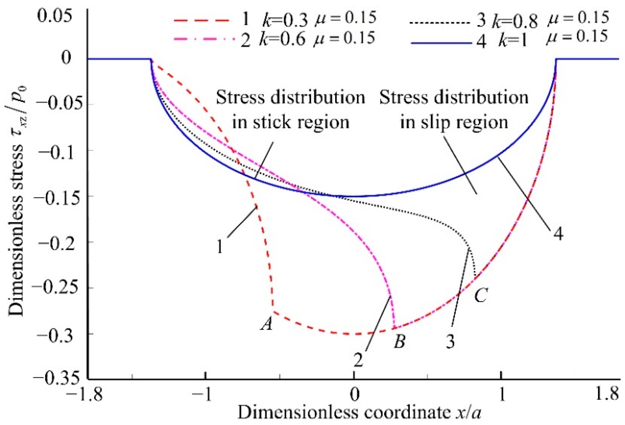
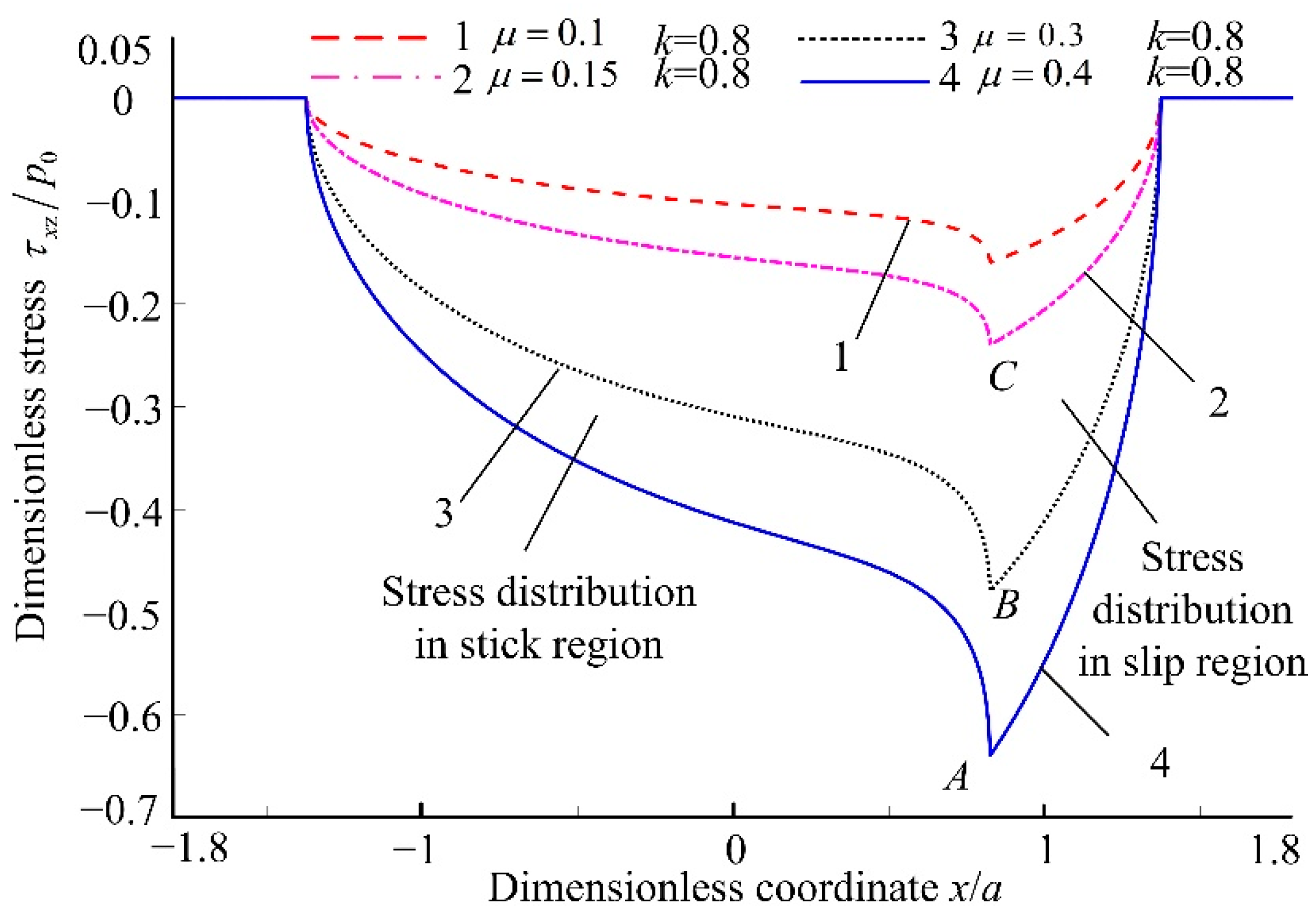
Figure 10 and Figure 11 show the effects of different friction coefficients µ and stick-slip coefficients k on stress components; when µ = 0.15 and y = 0 and varying values of k. The variation law of stress components τxz = p0 is shown in Figure 10.
When k = 1 the whole contact area is a stick region, there is no slip phenomenon or stress mutation in the contact ellipse. When k < 1, as k increases, the width of the stick region gradually increases, the contact stress gradually decreases. According to the position of the three points (stress mutation points A, B, and C), it can be analyzed that as k increases, the position of the stress mutation moves away from the rolling direction. At this time, the stick contact area increases, which proves that the stress mutation occurs at the stick-slip junction. The reason for this is as k increases, the creep phenomenon in the contact area decreases; therefore, the slip at the contact point decreases, and the stress mutation value decreases. In the slip region, the rate of change in the tangential stress component is independent of k. This is because in the slip region, the tangential friction is constant because the friction coefficient is constant, which provides the external tangential load of the tangential stress component.
Figure 11 shows that when k = 0.8, the variation of τxz = p0 for different µ. When the friction coefficient µ decreases, the stress of contact area decreases. Because the contact area satisfies Coulomb’s friction, as the friction coefficient decreases, the relative slip velocity in the rolling contact increases; therefore, the tangential force domain value for the relative slipping decreases, which makes it easier for relative sliding between the two contact bodies, but the impact caused by stress mutation is reduced.
When the k ≠ 1, regardless of the friction coefficient µ and k, there are compressive stress and tensile stress in the contact area. The stress mutation occurs at the junction of stick region and slip region. With the increase in k, the larger the stick region is, the less likely it is to slip between the rolling element and the variable diameter raceway, which makes the stress mutation in the contact area smaller and less likely to cause wear. Considering the two tangential stress components in the contact surface, it is beneficial to control the maximum stress in the contact area if the friction coefficient between the rolling element and the variable diameter raceway is reduced in the bearing design. However, it is easy to cause the macroscopic slipping phenomenon of rolling elements and the variable diameter raceway. Therefore, reducing the friction coefficient µ and increasing the stick-slip coefficient k appropriately can reduce stress mutation, thereby reducing the wear of rolling elements and variable diameter raceway. These measures can improve the service life of cageless bearings. From the perspective of kinematics, the excessive friction coefficient leads to large wear of the variable diameter raceway, which affects the effect of speed change when rolling elements pass through the variable diameter raceway. Finally, the discrete function of the variable diameter raceway fails more quickly. The above analysis shows that on the premise of ensuring the discretization of rolling elements, to reduce the wear of the variable diameter raceway and maintain the discrete effect to prolong the life of the bearing, it is reasonable to increase the stick-slip coefficient k and decrease the friction coefficient µ.

5. Experiment on Contact Characteristics of Cageless Bearing

To further demonstrate the contact stress when rolling elements pass through the variable diameter raceway, the equivalent strain experiment was used to test the cageless ball bearing, as shown in Figure 12. The experimental sample is processed combined with the geometric structure parameters of the cageless bearing in Table 1. According to the requirements of skill, the bearing sample was mounted onto the bearing testing measurement apparatus (model was BVT-1) with the outer ring fixed, and the variable diameter raceway was located at the lowest point. A radial load of 85 N was applied symmetrically at 45°, and the spindle speed was 1800 r/min. The rolling elements and the outer ring are in relative motion; hence, the foil strain gauge was pasted on the outer surface of the bearing where the variable diameter raceway is located. The foil strain gauge must be selected with a small size and high precision, due to the contact area at the variable diameter raceway being very small (model was bx120–1aa), to cooperate with the strain gauge (model was xl2101b6) to collect strain data.
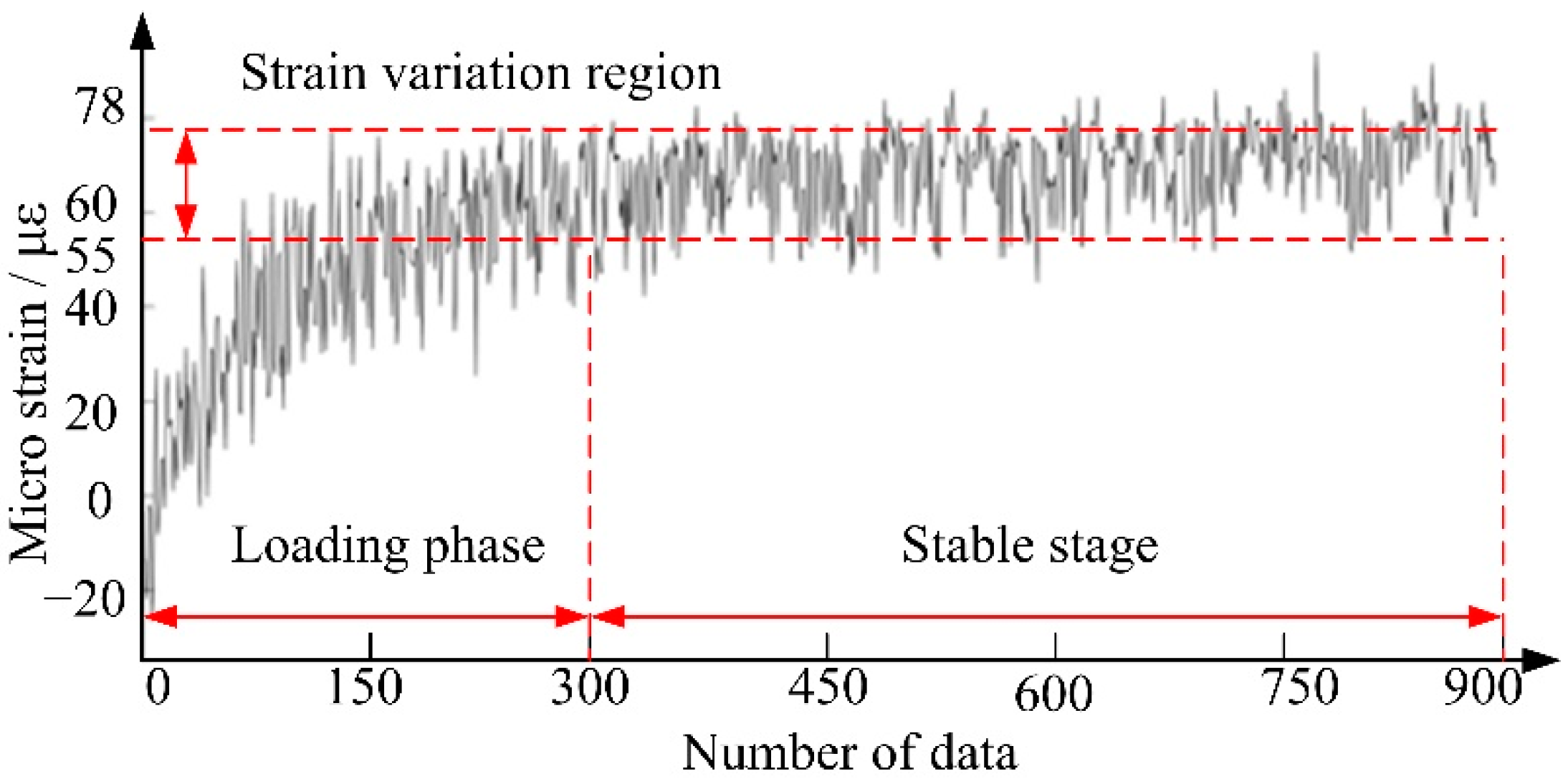
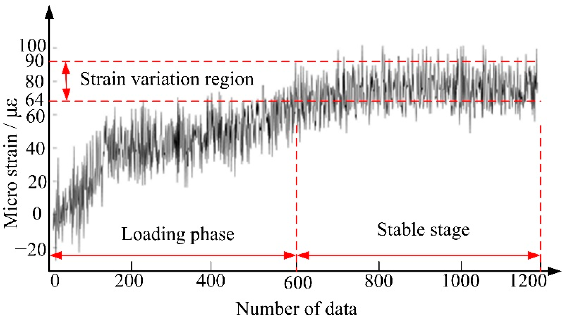
Combining Equations (8)–(12) and the relationship between stress and strain, it was obtained that the stress in the transition region between the rolling element and the variable diameter raceway is 621.7 MPa, and the contact stress in the variable diameter raceway is 224.444 MPa. Combined with the structure of the test sample, the stress distribution at a depth of 2 mm along the load direction is σz1 = 3.0855 MPa, the stress in the variable diameter raceway is σz2 = 0.0497 MPa after conversion. The contact strain between the rolling element and the transition region of the variable diameter raceway of the cageless ball bearing is εz1 = 2.269 × 10⁻⁵ on the surface, the micro strain is 22.69 µε. In the variable diameter raceway, the surface strain value is εz2 = 3.6538 × 10⁻⁷, the micro strain is 0.36538 µε. Through the calculation, it is observed that the strain in the variable diameter raceway is small relative to the strain in the transition region that it can be ignored. Thus, the strain gauges are only attached to the entry and exit of the variable diameter raceway, the strain data are collected to obtain the contact strain test results of the cageless ball bearing as shown in the Figure 13 and Figure 14.
When the bearing is running, as the radial load gradually increases, the strain data have an initial unstable stage. When the bearing is running stably, the data of 300–900 are selected as the stage of the rolling element entering the variable diameter raceway for analysis. The strain range is 55 με−78 με, and the micro-strain is 23 με. When the rolling element exits the variable diameter raceway, the data of 600–1200 are selected as the stable data. The strain range is 64 με−90 με, and the micro-strain is 26 με. The micro-strain of the rolling elements entering and exiting the variable diameter raceway is close to the theoretical calculation of 22.69 με. By comparing the experimental measured strain value with the theoretical distribution model calculation, the error of the stress distribution model at the starting position of the variable diameter raceway is 1.76%, and the error of the model at the ending position of the variable diameter raceway is 14.59%; the error is less than 15%. There are errors caused by objective factors such as the accuracy of the strain gauge and the uniformity of the outer ring of the bearing in the experimental process, but there is no significant difference. The above analysis shows that the stress distribution model can predict and characterize the contact stress distribution between the rolling elements and the variable diameter raceway. It has guiding significance for the design of the variable diameter raceway and the selection of operating conditions.

6. Conclusions

  • A new method for calculating the stress of three-dimensional nonconforming rolling contact between rolling elements and the variable diameter raceway was developed. The equations for analyzing the stress components were established. It was determined that the variable diameter raceway structure, spindle speed, friction coefficient and stick-slip coefficient are the main influencing factors of stress distribution. In addition, it was determined that the contact area is composed of two parts: the stick region and the slip region, the stress mutation often occurs at the boundary. The error of the new method for calculating is less than 15%. The correctness of the calculation method and the accuracy of the three-dimensional stress distribution model are verified, which can predict and characterize the contact stress distribution between the rolling elements and the variable diameter raceway.
  • As the radius of the curvature ri increases, the contact stress distribution gradually changes from the downward curve of the opening to the upward curve of the opening. When Ri = 25.19 mm and ri = 1.5 mm, the contact stress in the conventional raceway and the variable diameter raceway is equal. As the spindle speed increases, the maximum stress of stress distribution occurs in the reducer raceway. Therefore, the larger ri should be selected in the design of the variable diameter raceway. It is recommended that the rotation speed below 13,950 r/min is beneficial to reduce the stress impact during the process of rolling elements passing through the variable diameter raceway.
  • With the decrease in the friction coefficient µ and the increase in the stick-slip coefficient k, the stress mutation on the contact area of the rolling elements and variable diameter raceway reduces, which reduces the wear between the rolling element and variable diameter raceway. From the point of view of the discrete action, reducing µ and increasing the stick-slip coefficient k appropriately is beneficial to increase the service life of the variable diameter raceway.

Author Contributions

Conceptualization, Y.Z.; methodology and validation, Y.Z. and Q.W.; software, Q.W. and M.W.; formal analysis, Q.W.; investigation, Q.W. and M.W.; resources, Y.Z.; data curation, M.W. and Q.W.; writing—original draft preparation, Q.W.; writing—review and editing, Y.Z. and Q.W.; visualization, Q.W.; supervision, Y.Z.; project administration, Y.Z.; funding acquisition, Y.Z. All authors have read and agreed to the published version of the manuscript.

Funding

This research was funded by the National Natural Science Foundation of China (grant number 51875142), China.

Institutional Review Board Statement

Not applicable.

Informed Consent Statement

Not applicable.

Data Availability Statement

Please contact the corresponding authors.

Conflicts of Interest

The authors declare no conflict of interest.

References

  1. Silayev, B.M.; Danilenko, P.A. Method of calculating high-speed rolling bearings intended for an aircraft engine based on considering the wear process. J. Frict. Wear 2015, 36, 350–354. [Google Scholar] [CrossRef]
  2. Zhu, Y.; Zhang, Y.; Yu, C. Dynamic responses after rotor drops onto a new-type active eliminating protective clearance touchdown bearing. J. Mech. Sci. Technol. 2020, 34, 2277–2288. [Google Scholar] [CrossRef]
  3. Zhao, Y.; Wang, Q.; Wang, M.; Pan, C.; Bao, Y. Discrete theory of rolling elements for a cageless ball bearing. J. Mech. Sci. Technol. 2022, 36, 1921–1933. [Google Scholar] [CrossRef]
  4. Stribeck, R. Ball bearings for various loads. J. Trans. ASME 1907, 29, 420–463. [Google Scholar]
  5. Palmgren, A. Ball and Roller Bearing Engineering; SKF Industries Inc.: Philadelphia, PA, USA, 1959. [Google Scholar]
  6. Harris, T.A.; Kotzalas, M.N. Advanced Concepts of Bearing Technology: Rolling Bearing Analysis; CRC Press: Boca Raton, FL, USA, 2006. [Google Scholar]
  7. Ambrożkiewicz, B.; Syta, A.; Gassner, A.; Georgiadis, A.; Litak, G.; Meier, N. The influence of the radial internal clearance on the dynamic response of self-aligning ball bearings. Mech. Syst. Signal Processing 2022, 171, 108954. [Google Scholar] [CrossRef]
  8. Chudzik, A.; Warda, B. Effect of radial internal clearance on the fatigue life of the radial cylindrical roller bearing. Eksploat. Niezawodn. 2019, 21, 211–219. [Google Scholar] [CrossRef]
  9. Tomović, R. Load Calculation of the Most Loaded Rolling Element for a Rolling Bearing with Internal Radial Clearance. Appl. Sci. 2020, 10, 6934. [Google Scholar] [CrossRef]
  10. Qu, J.; Wang, W.; Han, H.; Liu, X. Study on Contact Analysis of High Angular Contact Ball Bearings Based on ANSYS. Mach. Des. Manuf. 2016, 8, 61–64. [Google Scholar] [CrossRef]
  11. Pandiyarajan, R.; Starvin, M.; Ganesh, K. Contact stress distribution of large diameter ball bearing using Hertzian elliptical contact theory. Procedia Eng. 2012, 38, 264–269. [Google Scholar] [CrossRef] [Green Version]
  12. Bozca, M. Effects of Design Parameters on Static Equivalent Stress of Radial Rolling Bearings. Acta Polytech. 2021, 61, 163–173. [Google Scholar] [CrossRef]
  13. Carter, F.W. On the action of a locomotive driving wheel. Proc. R. Soc. Lond. Ser. A 1926, 112, 151–157. [Google Scholar] [CrossRef]
  14. Reuss, M.; Sakai, T.; Matsubara, A. Modeling Approach for Estimation of Contact and Friction Behavior of Rolling Elements in Linear Bearings. Int. J. Autom. Technol. 2019, 13, 382–388. [Google Scholar] [CrossRef]
  15. Sen Gupta, S.K. Analytical and experimental studies of conical thrust ball bearings. Wear 1981, 69, 277–297. [Google Scholar] [CrossRef]
  16. Goryacheva, I.; Miftakhova, A. Modelling of the viscoelastic layer effect in rolling contact. Wear 2019, 430–431, 256–262. [Google Scholar] [CrossRef]
  17. Chen, Y.; Wang, P.J.; Sun, Y.L.; An, B.; Zhang, M.; Wang, P. Analysis of wheel-rail rolling contact behavior considering curved contact patch. J. China Railw. Soc. 2021, 43, 27–36. [Google Scholar] [CrossRef]
  18. Johnson, K.L. Contact Mechanics; Cambridge University Press: Cambridge, UK, 1987. [Google Scholar]
  19. Shcherbakov, S.S. Spatial stress-strain state of tribofatigue system in roll–shaft contact zone. Strength Mater. 2013, 45, 35–43. [Google Scholar] [CrossRef]
  20. Song, X.D.; Liu, S.D.; Xu, H.L. Checking method for static load capacity of angular contact ball bearing under axial load. Bearing 2020, 7, 5–8. [Google Scholar] [CrossRef]
  21. Toumi, M.; Murer, S.; Bogard, F.; Bolaers, F. Numerical simulation and experimental comparison of flaw evolution on a bearing raceway: Case of thrust ball bearing. J. Comput. Des. Eng. Optim. 2018, 5, 427–434. [Google Scholar] [CrossRef]
  22. Lee, D.-H.; Seo, J.-W.; Kwon, S.-J.; Choi, H.-Y. Three-dimensional transient rolling contact analysis of similar elastic cylinders. Procedia Eng. 2011, 10, 2633–2638. [Google Scholar] [CrossRef] [Green Version]
  23. Lostado, R.; Martinez, R.F.; Mac Donald, B.J. Determination of the contact stresses in double-row tapered roller bearings using the finite element method, experimental analysis and analytical models. J. Mech. Sci. Technol. 2015, 29, 4645–4656. [Google Scholar] [CrossRef]
  24. Kania, L. Modelling of rollers in calculation of slewing bearing with the use of finite elements. J. Mech. Mach. Theory 2006, 41, 1359–1376. [Google Scholar] [CrossRef]
  25. Bian, L.; Ma, J.; Huang, Q. Research on Condition Monitoring for Slewing Bearings Based on Stain Analysis. Bearing 2015, 11, 50–53. [Google Scholar] [CrossRef]
  26. Nagatomo, T.; Takahashi, K.; Okamura, Y.; Kigawa, T.; Noguchi, S. Effects of load distribution on life of radial roller bearings. J. Tribol. 2012, 134, 021101. [Google Scholar] [CrossRef]
  27. Yang, X.; Xiao, H. Analyzing Load Case of Mill Roller Bearing with Boundary Element Method. In Proceedings of the 2009 International Conference on Measuring Technology and Mechatronics Automation, Zhangjiajie, China, 11–12 April 2009; pp. 754–757. [Google Scholar]
  28. Yang, X.Q. Contact Mechanics Theory and Design Analysis of Rolling Bearing; Huazhong University of Science & Technology Press: Wuhan, China, 2018. [Google Scholar]
  29. Ping, L.; Wang, C.; Li, L. Contact Problems of Gothic-arc Bearing. J. Nanjing Univ. Sci. Technol. 2007, 31, 458–461. [Google Scholar] [CrossRef]
  30. Lu, Z.; Lu, Y.; Deng, S. Study on Load Distribution Characteristics of Cylindrical Roller Bearings with Trilobe Raceways. Bearing 2016, 9, 1–6. [Google Scholar] [CrossRef]
  31. Zhang, Z.; Deng, S.; Ju, H.W. Study on Processing for Non-Circular Raceway of Aerospace Trilobe Cylindrical Roller Bearings. Bearing 2019, 9, 13–17,20. [Google Scholar] [CrossRef]
  32. Zhang, X.; Luo, Y.; Zhang, Y. Influence of Raceway Shape on Mechanical Properties of Four-Point Contact Ball Bearings. Bearing 2014, 4, 40–42. [Google Scholar] [CrossRef]
  33. Wang, J. Geometric Design and Static Stress Analysis of Deep Groove Ball Bearing with Oval Raceway. Master’s Thesis, Northeastern University, Shenyang, China, 2014. [Google Scholar]
  34. Singh, A.P.; Agrawal, A.; Joshi, D. Contact Mechanics Studies for an Elliptical Curvature Deep Groove Ball Bearing Using Continuum Solid Modeling based on FEM Simulation Approach. IOSR J. Mech. Civ. Eng. 2016, 13, 1–11. [Google Scholar] [CrossRef]
  35. Kim, S.-W.; Kang, K.; Yoon, K.; Choi, D.-H. Design optimization of an angular contact ball bearing for the main shaft of a grinder. J. Mech. Mach. Theory 2016, 104, 287–302. [Google Scholar] [CrossRef]
  36. Niu, R.; Xu, J.; Shao, X.; Deng, S. Mechanical Properties Analysis of Asymmetric Double Row Four-point-contact Slewing Bearing. J. Mech. Eng. 2018, 54, 177–186. [Google Scholar] [CrossRef]
  37. Zhao, Y.; Zhang, X.; Qin, S. Design and simulation analysis of variable speed surface of cage-free bearing. J. Harbin Univ. Sci. Technol. 2021, 26, 33–39. [Google Scholar] [CrossRef]
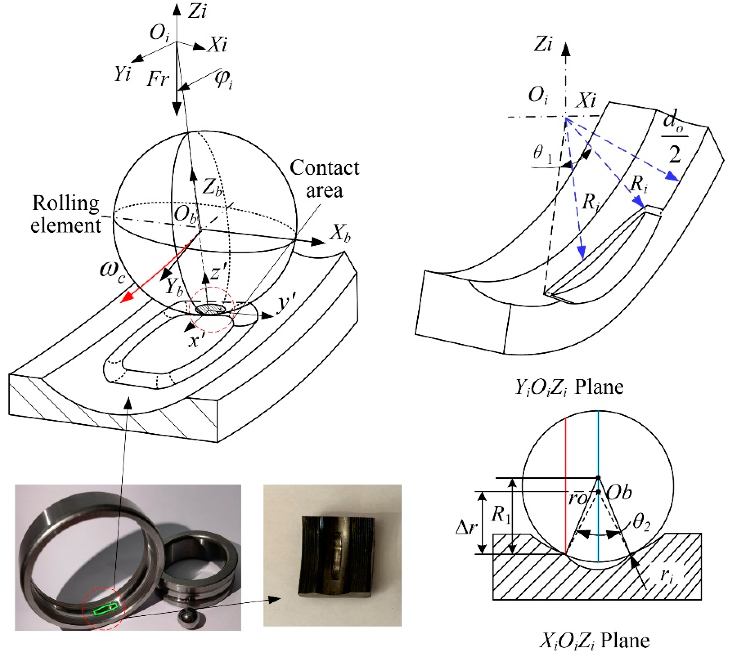
Figure 1. Structural model of cageless bearing with variable diameter raceway.
Applsci 12 05764 g001
Figure 2. State of contact area.
Applsci 12 05764 g002
Figure 3. Relationship between contact stress and position angle for different curvature radii: (a) The complete process of rolling elements movement, (b) transition region of variable diameter raceway, (c) The junction of the variable diameter raceway and the transition region.
Applsci 12 05764 g003
Figure 4. Relationship between contact stress and position angle for different speed.
Applsci 12 05764 g004
Figure 5. Distribution of dimensionless stress σx/p0 for k = 0.8 and µ = 0.15.
Applsci 12 05764 g005
Figure 6. Distribution of dimensionless stress σz/p0 for k = 0.8 and µ = 0.15.
Applsci 12 05764 g006
Figure 7. Distribution of dimensionless stress τxz/p0 for k = 0.8 and µ = 0.15.
Applsci 12 05764 g007
Figure 8. Stress σx/p0 for different values of k.
Applsci 12 05764 g008
Figure 9. Stress σx/p0 for different values of µ.
Applsci 12 05764 g009
Figure 10. Stress τxz/p0 for different values of k.
Applsci 12 05764 g010
Figure 11. Stress τxz/p0 for different values of µ.
Applsci 12 05764 g011
Figure 12. Strain test device for cageless ball bearing.
Applsci 12 05764 g012
Figure 13. Strain curve of rolling element entering variable diameter raceway.
Applsci 12 05764 g013
Figure 14. Strain curve of rolling element exiting variable diameter raceway.
Applsci 12 05764 g014
Table 1. Parameters of the cageless bearing and initial values in the numerical simulation.
ParameterNumericalParameterNumerical
Inner diameter30 mmX load0 N
Outer diameter62 mmY load500 N
Inner raceway diameter36.48 mmRolling element density3.18 g/cm3
Outer raceway diameter55.53 mmBearing ring density7.81 g/cm3
Ball diameter 9.525 mmRolling element Poisson’s ratio0.26
Inner raceway radius of curvature 4.905 mmBearing ring Poisson’s ratio0.3
Outer raceway radius of curvature 4.953 mmSpeed6 K–18 K RPM
Publisher’s Note: MDPI stays neutral with regard to jurisdictional claims in published maps and institutional affiliations.