Article

Finite-Time Consensus Tracking Control for Speed Sensorless Multi-Motor Systems

1
Shien-Ming Wu School of Intelligent Engineering, South China University of Technology, Guangzhou 510000, China
2
School of Electrical Engineering, Guangxi University, Nanning 530000, China
*
Author to whom correspondence should be addressed.
Appl. Sci. 2022, 12(11), 5518; https://doi.org/10.3390/app12115518
Submission received: 18 April 2022 / Revised: 22 May 2022 / Accepted: 25 May 2022 / Published: 29 May 2022

Abstract

:
Considering the unknown compound interference in manufacturing systems, the finite-time tracking and synchronization performance of the multi-motor system significantly affects the production safety, reliability, and quality, which can be considered a multi-agent system with unmeasured speed and uncertainty. In recent years, the synchronous control schemes of the multi-motor system have grown to maturity, but the research on the speed sensorless finite-time consensus tracking control remains to be extended. This paper proposes an observer-based leader–follower consensus tracking control for the synchronous coordination control of the multi-motor system. The speed and position of all motors can be tracked by consensus in a finite time when only some motors realize partial interaction. First, a finite-time observer is designed to estimate the unknown composite disturbance and unmeasurable speed variable of each motor. Second, the distributed finite-time consensus tracking control protocol is designed using the observed value and local information interaction. The stability of the overall closed-loop system is theoretically analyzed based on Lyapunov theory and graph theory, which shows that the consensus tracking error converges to an arbitrary small neighborhood of zero, and all signals are globally bounded in finite time. Finally, simulation results are provided to illustrate the effectiveness of the proposed control method.

1. Introduction

In the era of Industry 4.0, the growing scale and complexity of industrial production make it necessary to coordinate multiple motors to complete complex production tasks in many areas, such as printing, textile and high-precision machining [1]. The synchronous control accuracy of the multi-motor system directly affects the production efficiency and product quality. Improving the precision of the synchronous control can achieve significant benefits, including low cost, high adaptivity, and easy maintenance [2,3].
The existing synchronous control schemes of the multi-motor system mainly include uncoupled synchronous control and coupling synchronous control [4,5,6,7]. The uncoupled synchronous control strategy assumes that each team member can track the same command signal. Thus, the control method is simple and easy to implement. However, because members cannot share information, the control precision and robustness are not satisfactory when the motor system is subjected to external disturbances and parameter perturbation [8]. To our best knowledge, Koren first proposed the cross-coupling control scheme [9]. The distinguishing feature of this method is that the difference of position or velocity is used as the feedback signal of every team member to compensate for the deviation with the reference value. A novel method based on cross-coupling angle compensation was presented, which can realize the angle compensation of permanent magnet synchronous motors in offline or online conditions [10]. A cross-coupling control strategy based on second-order terminal sliding mode was applied to aim to improve the synchronization accuracy of dual-motor [11]. Chen et al. proposed a cross-coupled control strategy for the consensus tracking of multi-motor [12]. Moreover, researchers conducted considerable works on coupling synchronous control with modern control theory [13,14]. However, these control schemes inevitably produced a large number of intensive online calculations due to parameter coupling. To this end, it is necessary and meaningful to find a satisfactory synchronous control method with high synchronization performance.
The synchronization tracking problem of the multi-agent system can be regarded as the individual state variables gradually converge to the given desired state of the system, namely the goal is to asymptotically synchronize [15,16]. Compared with infinite settling time, the finite-time consensus control of multi-agent systems has been widely investigated in recent years because of its superior performance in improving the precision of synchronous control, and faster convergence rate [17]. In practice, the many required control systems need fast dynamic response such as multi-motor, robot operation, and spacecraft systems and the system error converges to zero in a finite time [18]. Unfortunately, most existing finite-time consensus control methods only focus on simple integrator models, such as first-order, second-order, and high-order integrators [19,20,21]. Zhang et al. proposed an observer-based variable structure consensus control to achieve the high-precision synchronous control [22]. Given the inevitable existence of parameter drift and unmodeled dynamics in an actual motor system, the desired performance is impossible to achieve by the application of a simplified-model-based consensus control in an actual multi-motor system such as a shaftless-driven printing press [23]. Moreover, when the speed of the leader changes, the followers should obtain the acceleration information of the leader, which is difficult or even impossible to quickly achieve in practical engineering [23,24]. Nevertheless, the angular position or velocity is assumed to be measurable in the above-cited research works. In practice, precise measurements may not be accessible and may be subject to the failure of onboard sensors or environmental perturbations. To address this issue, in the absence of speed information, the finite-time consensus protocol was designed based on the estimation of speed information [25,26]. Chen et al. investigated a class of nonlinear systems with uncertain states and an observer based on impulse control to estimate external disturbances [27,28,29]. Through linear matrix inequalities derivation and Lyapunov functions, the theoretical results are successfully applied to multi-link robots.
The concepts of the sensorless control solutions are to eliminate the hall sensors and optical encoders to obtain the position or speed information of the motors through some intelligent control algorithms [30]. In fact, the speed sensorless control schemes can reduce the encoder installed on the motor spindle and the decoder device on the control panel, and the speed signal will no longer be affected by the strong electromagnetic interference of the motor, which greatly improves the anti-interference ability and mechanical reliability of the multi-motor system [31,32]. Chen et al. proposed an adaptive observer to efficiently estimate the speed and identified the resistance with speed sensorless [33]. Considering the speed tracking performance under various uncertainties and disturbances, a sensorless speed controller for induction motors based on speed and perturbation estimation was presented by defining nonlinear dynamics and external disturbances [34]. To solve a class of high-order nonlinear systems with mismatched external disturbances and uncertainties, researchers had developed state observers to provide an on-line state estimator for control systems [35]. The unmeasured states and unmatched disturbances were estimated by an extended state observer, and a finite-time consensus protocol was designed based on the output feedback using the adding power integration method [36].
Inspired by the above mentioned works and industrial requirements, an observer-based finite-time leader–follower consensus tracking control method is proposed for the synchronous coordination control of the multi-motor system in this study. The main contributions of this paper are reflected as follows: (1) Many existing control strategies can obtain a stable synchronization system, but the obtained stable system may encounter large parameter perturbation or interference that causes loss of synchronization performance. A feedback consensus protocol is developed based on the disturbance estimation/compensation, which can actively suppress the uncertainty and chattering. Compared to the passive anti-disturbance control strategy, the cooperative tracking performance of the multi-motor system can be improved; (2) The distributed finite-time state observers are designed to estimate the speed of each agent when only part of the motors interact locally. It means that there is no need to measure the speed of all motors and only partial agents receive the reference signal to complete the synchronization tracking process, which are easy to implement in practice. The speed sensorless control strategy avoids intensive on-line computational work and improves the mechanical reliability of the system; (3) Based on local information interaction, the proposed distributed finite-time consensus control studied the synchronization and tracking of second-order multi-agent systems with nonlinear properties and external disturbance. Compared with the existing control strategies, the proposed control method exhibits higher synchronization control accuracy through rigorous theoretical proof and numerical simulation.
The remainder of this paper is organized as follows. Section 2 describes the mathematical model of the motor with parameter perturbation and necessary lemmas. The finite-time observer design and its convergence analysis are provided in Section 3. Section 4 illustrates the design of the finite-time consensus tracking protocol based on the output feedback. Moreover, the analysis of the stability of the closed-loop system is presented by using the adding a power integrator method. Section 5 verifies the proposed method by simulations. The summary is presented in Section 6.

2. Preliminaries and Problem Formulation

2.1. Graph Theory

Consider a multi-motor system consisting of one leader and n followers, where motor 0 (L) is the virtual leader, and motors 1, 2, …, n are the followers. Each motor can be considered a node in the multi-agent network. The data interaction between motors is realized through communication network, which can be represented by graph theory [5,26,37]. G n = { V n , E n } is an undirected graph, where the vertex set V n = { v 1 , v 2 , , v n } refers to n motors and the edge set E n = v i , v j v i , v j V n ( i , j = 1 , 2 , , n ) refers to the interactions among motors. v i , v j E n denotes that nodes v i and v j can receive information from each other. The adjacency matrix, which indicates the connection weight between nodes v i and v j for the undirected graph is A n = [ a i j ] R n × n , where a i j = 0 , if v i , v j E n and a i j > 0 , if v i , v j E n . In addition, the self-loop condition is not considered in the paper, i.e., for i = 1 , , n , a i i = 0 . The Laplacian matrix related to L = [ l i j ] R n × n is defined as l i i = i j a i j and l i j = a i j , where i j . Assume that the diagonal matrix B = d i a g { a 10 , , a n 0 } refers to the weight matrix between the followers and the leader. If a i 0 > 0 , then the matrix indicates that i follower can obtain the information of the leader. Otherwise, a i 0 = 0 .

2.2. Lemmas

To facilitate the subsequent theoretical analysis, the following lemmas are provided.
Lemma 1
([36]). Suppose V : D R is a continuous function satisfying: (1) V is positive definite; (2) There exist real numbers c > 0 , α ( 0 , 1 ) , 0 < γ < , and an open region U D near the origin such that: V ˙ ( x , t ) c V ( x , t ) α + γ , x ( t ) U \ { 0 } . There exists a finite time T * V ( x , 0 ) 1 α ( 1 μ ) c ( 1 α ) , 0 < μ < 1 . When t T * , V ( x , t ) is bounded by V ( x , t ) γ μ c 1 α .
Lemma 2
([38]). x , y R , if 0 < q = q 1 / q 2 1 , q 1 > 0 and q 2 > 0 are positive odd integers. Then one has x q y q 2 1 q x y q .
Lemma 3
([38]). For any real numbers x , y , λ , c > 0 , and d > 0 , one has x c y d c c + d λ x c + d + d c + d λ c / d y c + d .
Lemma 4
([38]). For x i R , i = 1 , 2 , , n , 0 < p < 1 , the following inequality holds: ( x 1 + + x n ) p x 1 p + + x n p .

2.3. Problem Description

The dynamics of each motor is governed by [39]:
θ ˙ i = ω i ω ˙ i = K t i K e i J i R i ω i + K t i J i R i u i 1 J i T L i i = 1 , 2 , , n ,
where θ i is the angular position of motor i, ω i is the angular velocity of motor i, u i is the control input, R i is the total armature resistance, K e i is the voltage feedback coefficient, J i is the moment of inertia, K t i is the electromagnetic torque coefficient, and T L i is the load torque of motor i.
We consider that the parameters vary with time during the actual operation of the motor. These parameters such as the resistance, inductance can change with different temperature. Therefore, we set k i = ( K t i K e i K t i K e i J i R i J i R i ) , b i = K t i K t i J i R i J i R i and c i = 1 1 J i J i , where k i = k ¯ i + Δ k i , b i = b ¯ i + Δ b i , and c i = c ¯ i + Δ c i . k ¯ i , b ¯ i , c ¯ i are the nominal parts of system parameters k i , b i , c i . Δ k i , Δ b i , Δ c i are the perturbed values. The parameter perturbation and load torque are unified as unknown composite disturbances, i.e., d i = Δ k i ω i + Δ b i u i + c i T L i . Thus, Equation (2) can be written as follows:
θ ˙ i = ω i ω ˙ i = k ¯ i ω i + b ¯ i u i + d i i = 1 , 2 , , n .
Assuming that motor 0 is a virtual leader, the kinetic equation of the virtual leader is:
θ ˙ 0 = ω 0 ω ˙ 0 = k ¯ 0 ω 0 + b ¯ 0 u 0 .
The objective of this study is to design a finite-time observer to estimate the speed and unknown composite disturbance in the absence of speed information, and the estimated value is fed back to the controller. The finite-time consensus protocol based on the output feedback is designed to make the state of each follower consistent with the state of the virtual leader, i.e.,
lim t T θ i θ 0 = 0 , lim t T ω i ω 0 = 0 .

3. Finite-Time Convergent Observer Design

In practical engineering, all state variables of the system are difficult to obtain because of the limitation of technical conditions. The lack of some state information hampers the achievement of the control protocol based on the full state feedback. Thus, the unknown compound interference must be accurately estimated and fed back to the controller to reduce the influence of high-frequency chattering. To this end, input u i and output θ i of the system (2) are used to estimate the unmeasurable speed variable ω i and unknown compound interference d i of the system in this section.
Let θ ^ i , ω ^ i , d ^ i denote the estimates associated with states θ i , ω i and uncertainty d i , respectively. e i 1 and e i 2 denote the state estimation errors, which are defined as e i = e i 1 e i 2 T = θ i θ ^ i ω i ω ^ i T .
When the unknown state and interference is out of certain scope, the system will lose synchronization and produce high-frequency chattering. To precisely estimate unmeasured states ω i and uncertainty d i , we design the following finite-time observer for system (2):
θ ^ ˙ i = ω ^ i + l i 1 e i 1 1 2 sgn ( e i 1 ) ω ^ ˙ i = k ¯ i ω ^ i + b ¯ i u i + l i 2 sgn ( e i 1 ) ,
where l i 1 and l i 2 are the observer gains to be designed later.
Theorem 1.
In the multi-motor system, the parameters to be designed of the finite-time observers satisfy the following:
l i 1 p 11 + l i 2 p 12 > 0 p 12 ( l i 1 p 11 + l i 2 p 12 ) ( l i 2 p 22 + l i 1 2 p 12 1 2 p 11 ) 2 > 0 ,
where p i j ( i , j = 1 , 2 ) is the element of symmetrical positive definite matrix P. The observer error will converge to an arbitrary small neighborhood of zero in finite time T 1 , and the estimated value of the composite disturbance can be described by lim t T 1 d ^ i = l i 2 sgn ( e i 1 ) e i 2 .
Proof. 
Subtracting Formula (5) from (2), the error dynamics can be obtained as follows:
e ˙ i 1 = e i 2 l i 1 e i 1 1 2 sgn ( e i 1 ) e ˙ i 2 = k ¯ i e i 2 l i 2 sgn ( e i 1 ) + d i .
To examine the convergence of the observer, the Lyapunov function is selected as follows:
U i = ξ i T P ξ i ,
where the auxiliary variable is ξ i T = e i 1 1 2 sgn ( e i 1 ) e i 2 T , and the symmetrical positive definite matrix is P = p 11 p 12 p 12 p 22 . If the parameters of matrix P satisfy p 11 > 0 ,   p 11 p 22 p 12 2 > 0 , the Lyapunov function U i is positive definite, as follows:
λ min ( P ) ξ i T ξ i U i λ max ( P ) ξ i T ξ i .
Finding the derivation of U i along the system trajectory (8) yields:
U ˙ i = 2 e i 1 1 2 sgn ( e i 1 ) 2 e i 2 P × 1 2 e i 1 1 2 ( e i 2 l i 1 e i 1 1 2 sgn ( e i 1 ) ) k ¯ i e i 2 l i 2 sgn ( e i 1 ) + d i = 2 [ 1 2 sgn ( e i 1 ) p 11 e i 2 + 1 2 1 e i 1 1 2 e i 2 p 12 e i 2 1 2 p 11 l i 1 e i 1 1 2 sgn 2 ( e i 1 ) 1 2 e i 2 p 12 l i 1 sgn ( e i 1 ) + k ¯ i e i 1 1 2 sgn ( e i 1 ) e i 2 p 12 + e i 2 T p 22 k ¯ i e i 2 l i 2 p 12 e i 1 1 2 sgn 2 ( e i 1 ) l i 2 e i 2 T sgn ( e i 1 ) p 22 + d i e i 1 1 2 sgn ( e i 1 ) p 12 + d i e i 2 T p 22 ] .
The following can be obtained:
U ˙ i 1 e i 1 1 2 e i 1 1 2 sgn ( e i 1 ) e i 2 × l i 1 p 11 + l i 2 p 12 l i 2 p 22 + l i 1 2 p 12 1 2 p 11 l i 2 p 22 + l i 1 2 p 12 1 2 p 11 p 12 × e i 1 1 2 sgn ( e i 1 ) e i 2 + ( p 12 e i 1 1 2 sgn ( e i 1 ) + e i 2 T p 22 ) × ( k ¯ i e i 2 + d i ) .
Denote Q i = l i 1 p 11 + l i 2 p 12 l i 2 p 22 + l i 1 2 p 12 1 2 p 11 l i 2 p 22 + l i 1 2 p 12 1 2 p 11 p 12 , the following inequality can obtain:
U ˙ i 1 e i 1 1 2 ξ i T Q i ξ i + m i ,
where m i = 2 p M ξ i ( k ¯ i e i 2 + d i ) , p M = max { p 12 , p 22 } . Moreover, observe that ξ i 2 = e i 1 + e i 2 2 , e i 1 1 2 U 1 2 λ min 1 2 ( P ) , then U ˙ i 1 e i 1 1 2 λ min ( Q i ) λ min ( P ) U + m i λ min ( Q i ) λ min 1 2 ( P ) U 1 2 + m i .
According to Lemma 1, the observer error will converge to the region Ω = { ( e i 1 , e i 2 } ) : e i 1 + e i 2 2 ( λ min 1 2 ( P ) m i μ i λ min ( Q i ) ) 2 } in the finite time T 1 = 2 λ min 1 2 ( P ) U ( ξ i , 0 ) 1 2 ( 1 μ i ) λ min ( Q i ) , where 0 < μ i < 1 , and the matrices P and Q i can be selected to make the error sufficiently small.
δ i > 0 , when t < T 1 :
d ^ i d i < δ i .
when t > T 1 , e i 1 , e i 2 will converge to the region Ω near the origin. According to (7), the estimated value of the unknown composite disturbance can be obtained as follows:
lim t T 1 d ^ i = l i 2 sgn ( e i 1 ) e i 2 .
The proof is completed. □

4. Finite-Time Consensus Tracking Protocol Design

In this section, the unmeasured speed variable and estimated value of unknown compound interference are introduced into the design of the consensus protocol under the premise of speed sensorless. The control protocol does not need to use all status information. First, the consensus tracking error is defined as follows:
σ i = j N i a i j ( θ i θ j ) + a i 0 ( θ i θ 0 ) ,
where N i is the set of neighbors for the motor. For multi-motor system (2), the finite-time consensus tracking protocol based on the output feedback is designed as follows:
u i = 1 b ¯ i ( k ¯ i ω ^ i d ^ i q 1 [ ω i p + q 2 p σ i ] 2 / p 1 ) , i = 1 , 2 , , n ,
where 1 < p = p 1 / p 2 < 2 , p 1 and p 2 are positive odd numbers; q 1 and q 2 are the positive constants to be designed; ω ^ i and d ^ i are the estimated values ω i and d i .
Theorem 2.
For multi-motor system (2), under the action of the consensus protocol (16), let parameters q 1 and q 2 satisfy the following inequality:
q 1 ( 2 1 / p ) 2 1 1 / p q 2 1 + p ( q 5 + q 6 ) q 2 = p 2 1 1 p 1 + p + α + n γ 1 + p + q 5 ,
where q 3 = 2 1 1 p α + α q 2 p 1 + p + n γ p · 2 1 1 / p + q 2 1 + p , q 4 = 1 q 2 γ 2 1 1 / p 1 + p , q 6 = q 3 q 2 + n q 4 + 2 1 1 p 1 + p , and α = max { j N i a i j } , γ = max { a i j , i , j } . Then, the consensus error will converge to an arbitrary small neighborhood of zero in finite time.
Proof. 
The construction of the controller is mainly based on the inverse recursive design method, and the proof is divided into two steps.
Step 1: A positive definite Lyapunov function is constructed as follows:
V 0 = 1 2 i = 1 n j N i a i j ( θ i θ j ) 2 + 1 2 i = 1 n a i 0 ( θ i θ 0 ) 2 .
The communication topology is an undirected graph. Thus, the following equation is obtained by finding the derivation of V 0 :
V ˙ 0 = i = 1 n j N i a i j ( θ i θ j ) T ( ω i ω j ) + i = 1 n a i 0 ( θ i θ 0 ) T × ( ω i ω 0 ) = i = 1 n j = 0 n a i j ( θ i θ j ) T ω ¯ i = i = 1 n j = 0 n a i j ( θ i θ j ) T ( ω i * + ( ω ¯ i ω i * ) ) ,
where ω ¯ i = ω i ω j . The virtual control law is designed as ω i * = q 2 σ i 1 / p . Substituting the virtual control law into Formula (19) yields:
V ˙ 0 = i = 1 n j = 0 n a i j ( θ i θ j ) T ( ω i * + ( ω ¯ i ω i * ) ) = i = 1 n σ i ω i * + i = 1 n σ i ( ω ¯ i ω i * ) q 2 i = 1 n σ i 1 + 1 / p + i = 1 n σ i ω ¯ i ω i * .
Let ρ i = ω ¯ i p ω i * p . Then, according to Lemmas 2 and 4, one can obtain:
V ˙ 0 q 2 i = 1 n σ i 1 + 1 / p + i = 1 n σ i ω ¯ i ω i * q 2 i = 1 n σ i 1 + 1 / p + i = 1 n σ i 2 1 1 / p ω ¯ i p ω i * p 1 / p q 2 i = 1 n σ i 1 + 1 / p + i = 1 n 2 1 1 / p ( p σ i 1 + 1 / p 1 + p + ρ i 1 + 1 / p 1 + p ) .
Step 2: The following Lyapunov function is constructed:
V = V 0 + i = 1 n V 1 i
where V 1 i = 1 ( 2 1 / p ) 2 1 1 / p q 2 1 + p ω i * ω ¯ i ( τ p ω i * p ) 2 1 / p d τ , and V 1 i is a positive definite function. Finding the derivation of V 1 i yields:
V ˙ 1 i = ( k ¯ i ω i + b ¯ i u i + d i ) ( 2 1 / p ) 2 1 1 / p q 2 1 + p ρ i 2 1 / p 1 2 1 1 / p q 2 1 + p ( d ω i * p d t ) ω i * ω ¯ i ( τ p ω i * p ) 1 1 / p d τ .
Because d ( ω i * p ) d t = q 2 p j N i a i j ( ω i ω j ) + a i 0 ( ω i ω 0 ) q 2 p ( α ω ¯ i + γ m = 1 n ω m ) , where ω m = ω i ω 0 , α = max { j N i a i j } , γ = max { a i j , i , j } , and ω i * ω ¯ i ( τ p ω i * p ) 1 1 / p d τ ω ¯ i ω i * ρ i 1 1 / p , it is substituted in Equation (23). Thus,
V ˙ 1 i ( k ¯ i ω i + b ¯ i u i + d i ) ( 2 1 / p ) 2 1 1 / p q 2 1 + p ρ i 2 1 / p + ( α ω ¯ i + γ m = 1 n ω m ) 2 1 1 / p q 2 ω ¯ i ω i * ρ i 1 1 / p .
According to Lemmas 2 and 3, the following inequalities are obtained:
ω ¯ i ω ¯ i ω i * ρ i 1 1 / p 2 1 1 / p ω ¯ i ρ i 1 / p ρ i 1 1 / p = 2 1 1 / p ω ¯ i ρ i 2 1 1 / p ( ω ¯ i ω i * + ω i * ) ρ i 2 1 1 / p ( 2 1 1 / p ρ i 1 + 1 / p + q 2 ρ i σ i 1 / p ) 2 1 1 / p ( 2 1 1 / p ρ i 1 + 1 / p + q 2 1 + p σ i 1 + 1 / p + q 2 p 1 + p ρ i 1 + 1 / p )
ω m ω ¯ i ω i * ρ i 1 1 / p 2 1 1 / p ω m ρ i 1 / p ρ i 1 1 / p = 2 1 1 / p ω m ρ i 2 1 1 / p ( ω m ω m * + ω m * ) ρ i 2 1 1 / p ( 2 1 1 / p ρ m 1 / p + q 2 σ m 1 / p ) ρ i 2 1 1 / p ( ( 2 1 1 / p + q 2 ) p 1 + p × ρ i 1 + 1 / p + 2 1 1 / p 1 + p ρ m 1 + 1 / p + q 2 1 + p σ m 1 + 1 / p ) .
Substituting (25) and (26) into (24) yields the following equation:
V ˙ 1 i 1 q 2 ( α ( 2 1 1 / p ρ i 1 + 1 / p + q 2 1 + p σ i 1 + 1 / p + q 2 p 1 + p ρ i 1 + 1 / p ) + γ m = 1 n ( 2 1 1 / p 1 + p ρ m 1 + 1 / p + q 2 1 + p σ m 1 + 1 / p ) + n p γ ( 2 1 1 / p + q 2 ) 1 + p ρ i 1 + 1 / p ) + 1 ( 2 1 / p ) 2 1 1 / p q 2 1 + p ρ i 2 1 / p ( k ¯ i ω i + b ¯ i u i + d i ) q 3 q 2 ρ i 1 + 1 / p + α 1 + p σ i 1 + 1 / p + q 4 m = 1 n ρ m 1 + 1 / p + γ 1 + p m = 1 n σ m 1 + 1 / p + ( k ¯ i ω i + b ¯ i u i + d i ) ( 2 1 / p ) 2 1 1 / p q 2 1 + p ρ i 2 1 / p .
The following equation is obtained by combining Equations (21), (22) and (27).
V ˙ ( q 2 p 2 1 1 / p 1 + p α + n γ 1 + p ) i = 1 n σ i 1 + 1 / p + ( 2 1 1 / p 1 + p + q 3 q 2 + n γ 2 1 1 / p q 2 ( 1 + p ) ) i = 1 n ρ i 1 + 1 / p + 1 ( 2 1 / p ) 2 1 1 / p q 2 1 + p i = 1 n ρ i 2 1 / p ( k ¯ i ω i + b ¯ i u i + d i ) .
According to Theorem 2, substituting Formula (16) into (28) yields:
V ˙ q 5 i = 1 n σ i 1 + 1 / p + q 6 i = 1 n ρ i 1 + 1 / p q 1 ( 2 1 / p ) 2 1 1 / p q 2 1 + p i = 1 n ρ i 2 1 / p ( ω i p + q 2 p σ i ) 2 / p 1 + i = 1 n ρ i 2 1 / p ( k ¯ i e i 2 + δ i ) ( 2 1 / p ) 2 1 1 / p q 2 1 + p .
Because the virtual control law ω i * = q 2 σ i 1 / p , ( ω i p + q 2 p σ i ) 2 / p 1 = ρ i 2 / p 1 can be calculated. Substituting Formula (17) into (29) yields:
V ˙ q 5 i = 1 n σ i 1 + 1 / p q 5 i = 1 n ρ i 1 + 1 / p + i = 1 n ρ i 2 1 / p ( k ¯ i e i 2 + δ i ) ( 2 1 / p ) 2 1 1 / p q 2 1 + p .
Because i = 1 n σ i 2 = ( L 1 / 2 θ ¯ ) T ( L 1 / 2 θ ¯ ) λ 2 ( L ) ( θ ¯ ) T ( θ ¯ ) , where θ ¯ = θ i θ j and V 1 i ω i ω i * ω i p ω i * p 2 1 p ( 2 1 p ) 2 1 1 / p q 2 1 + p ρ i 2 ( 2 1 / p ) q 2 1 + p , one can obtain V = V 0 + i = 1 n V 1 i c 1 ( i = 1 n σ i 2 + i = 1 n ρ i 2 ) and c 1 = max { λ 2 ( L ) , 1 ( 2 1 / p ) q 2 1 + p } . The following can be obtained using Lemma 4:
V 1 2 + 1 2 p c 1 1 2 + 1 2 p i = 1 n σ i 1 + 1 / p + i = 1 n ρ i 1 + 1 / p .
The following formula is obtained by combining Formulas (30) and (31):
V ˙ q 5 c 1 1 2 + 1 2 p V 1 2 + 1 2 p + ζ ,
where ζ = i = 1 n ρ i 2 1 / p ( k ¯ i e i 2 + δ i ) ( 2 1 / p ) 2 1 1 / p q 2 1 + p , denote c 2 = q 5 c 1 1 2 + 1 2 p . According to Lemma 1, the convergence time is t s = 2 p V ( 0 ) 1 2 1 2 p ( 1 μ ) c 2 ( p 1 ) , and V ( ζ μ c 2 ) 2 p p + 1 , t > t s . The consensus tracking error will converge to the region σ i ( 2 ( ζ μ c 2 ) p p + 1 ) within the finite time. The consensus tracking error is guaranteed to be sufficiently small by selecting the proper parameters.
The proof is completed. □

5. Simulations

In this section, a simulation example is provided to verify the effectiveness of the proposed method. Five nonidentical servo motors 0 (L), 1, 2, 3, and 4 are used in the simulation. Motor 0 is assumed to be the virtual leader and motors 1, 2, 3, and 4 are all the followers. Apparently, the reference signal is only transmitted to the virtual leader and all the followers are able to track the motion of the virtual leader. The communication and interaction among motors are shown in Figure 1, and the parameter settings of all motors are shown in Table 1. Each follower realizes the overall consensus through the local information exchange. If motor i and motor j exchange their information, a i j = a j i = 1 , i j . Otherwise, a i j = a j i = 0 , i j . If motor i exchanges information with the leader, a i 0 = 1 . Otherwise, a i 0 = 0 .
A = 0 1 1 0 1 0 0 0 1 0 0 1 0 0 1 0 , B = 1 0 0 0
To verify the effectiveness of the proposed method, four different disturbance signals are adopted: d 1 = 15 sin ( 3 t ) , d 2 = 12 cos ( 5 t ) , d 3 ( t ) = 15 cos ( 5 t ) e 0.3 t , d 4 = 13 sin ( 3 t ) + 3 cos ( 5 t ) , to simulate the uncertainty of each motor. During the simulation experiment, the parameter matrix of the finite-time observer is set as: l 1 = l 11 l 12 T = 20 45 T , l 2 = l 21 l 22 T = 21 43 T , l 3 = l 31 l 32 T = 22 44 T , l 4 = l 41 l 42 T = 23 45 T . The gain of the consensus control protocol is set to q = q 1 q 2 T = 50 10 T .

5.1. Performance Evaluations of Observers

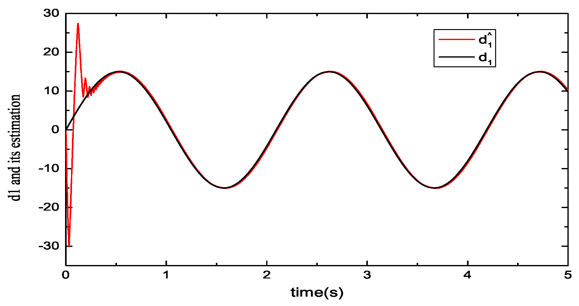
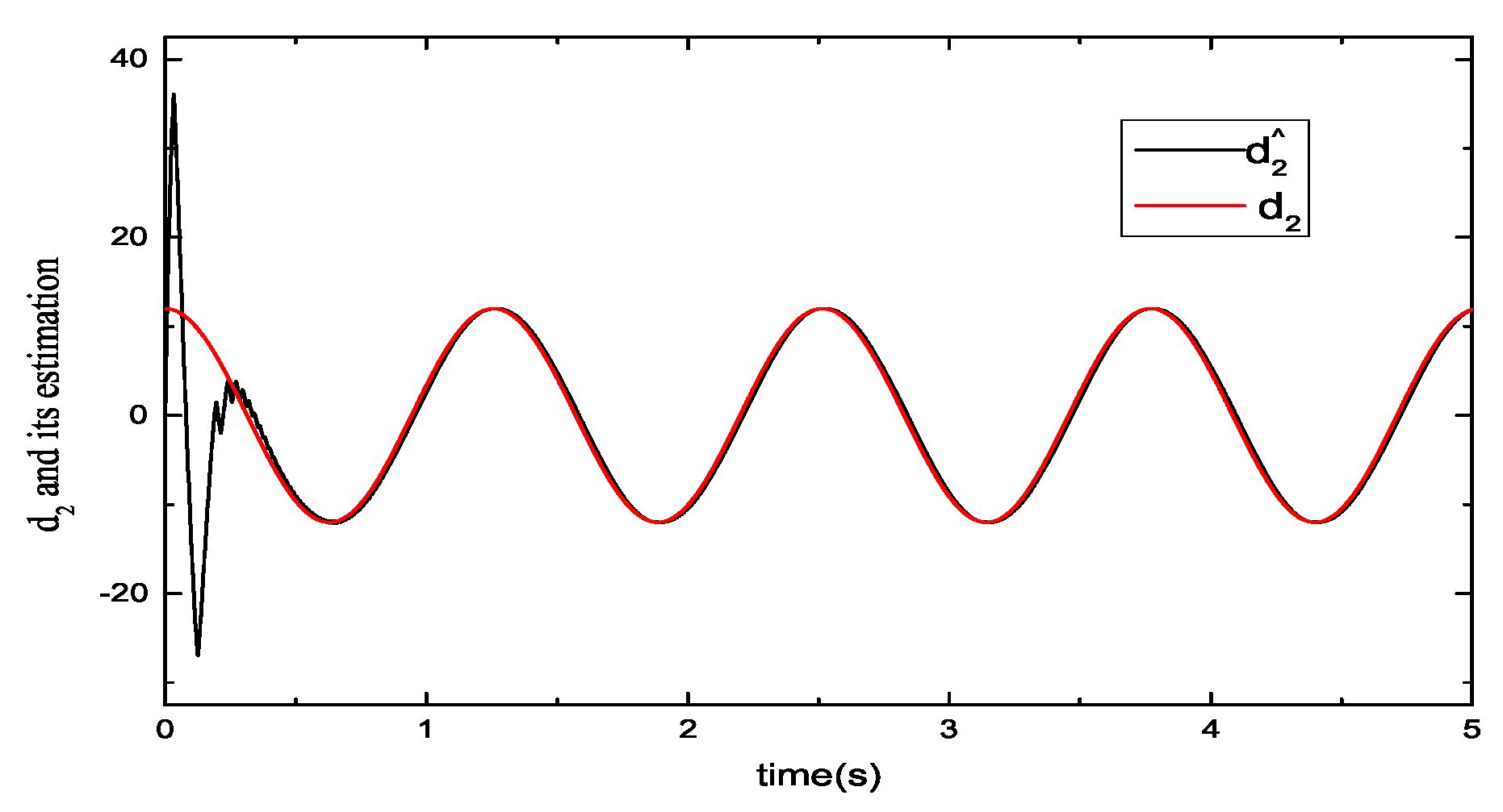
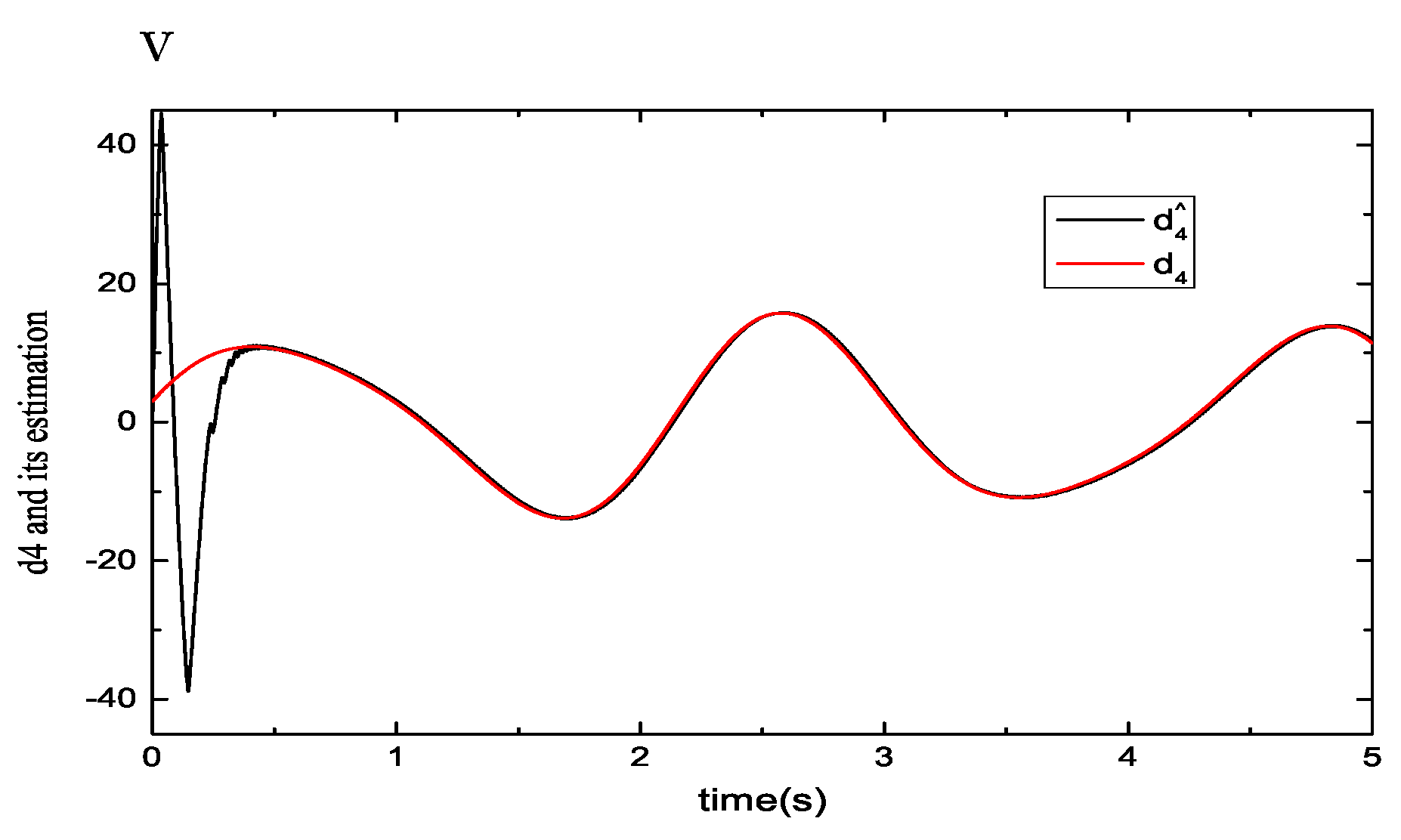
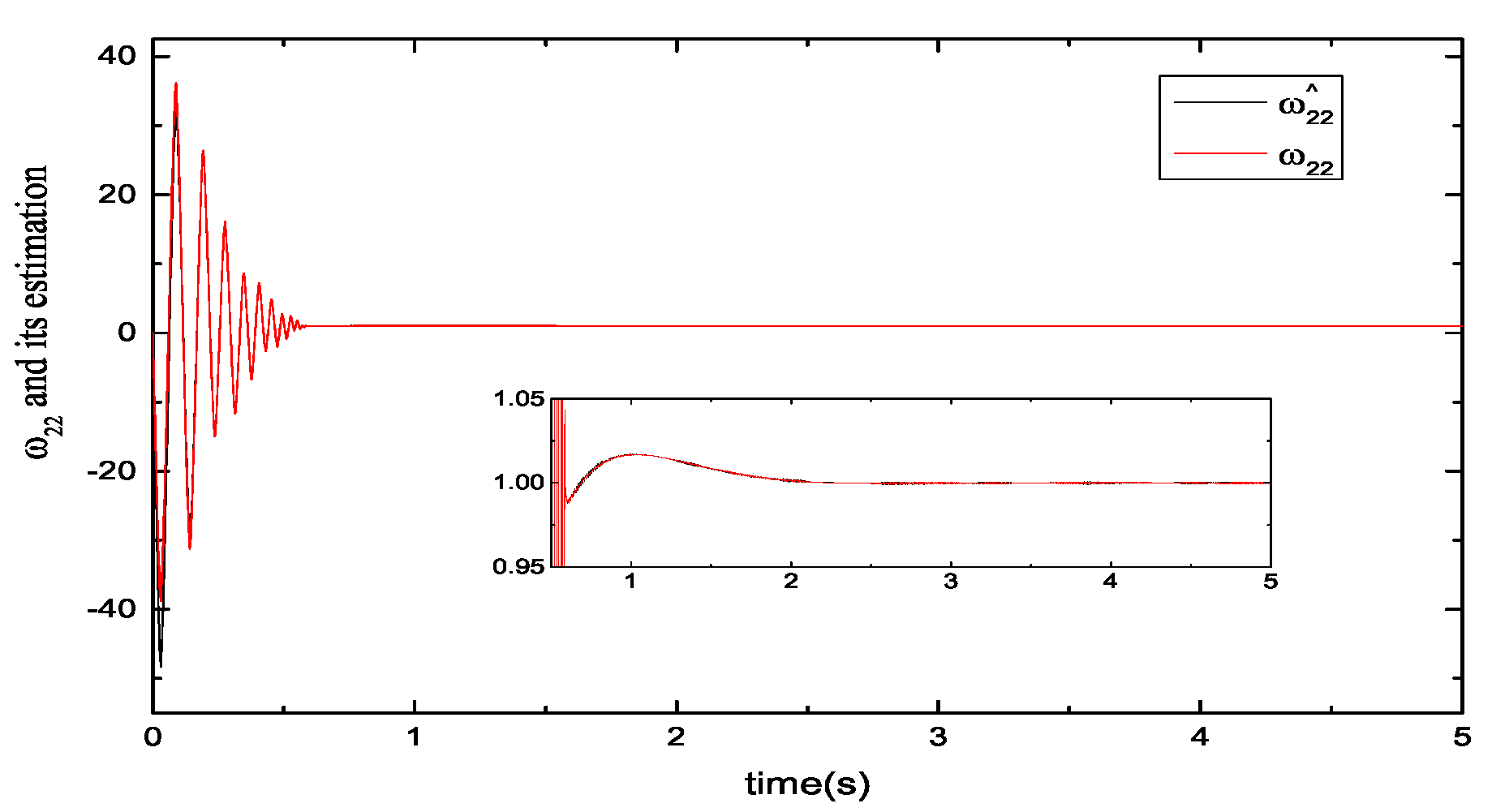
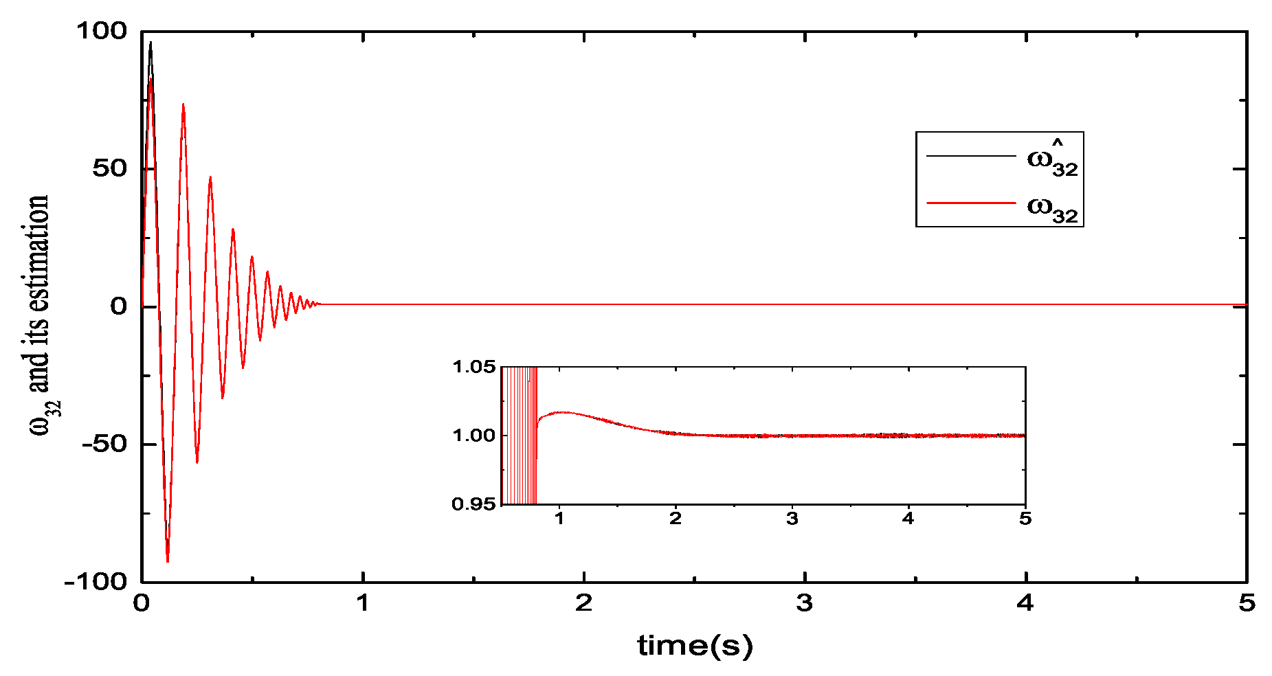
The estimated accuracy of the disturbance directly determines the performance of the following controllers. First, the disturbance observers are designed and evaluated. To verify the performance of the disturbance observers, four disturbance signals d 1 , d 2 , d 3 and d 4 are added to the follower motors 1, 2, 3 and 4, respectively. Figure 2, Figure 3, Figure 4 and Figure 5 show the comparison of four disturbance signal curves and corresponding observed value curves. From Figure 2, it shows that the disturbance value of motor 1 and its estimated value achieve consensus tracking after 0.5 s and the maximum steady-state error ratio of the observer is 0.575%. Similarly, from Figure 3, Figure 4 and Figure 5, it can be concluded that the maximum tracking time of the observers is 0.45 s, 0.55 s, and 0.55 s, respectively. The maximum steady-state error ratios of all the observers are 0.575%, 0.66%, 0.575%, and 0.642%, which satisfy the requirements of the controller design.
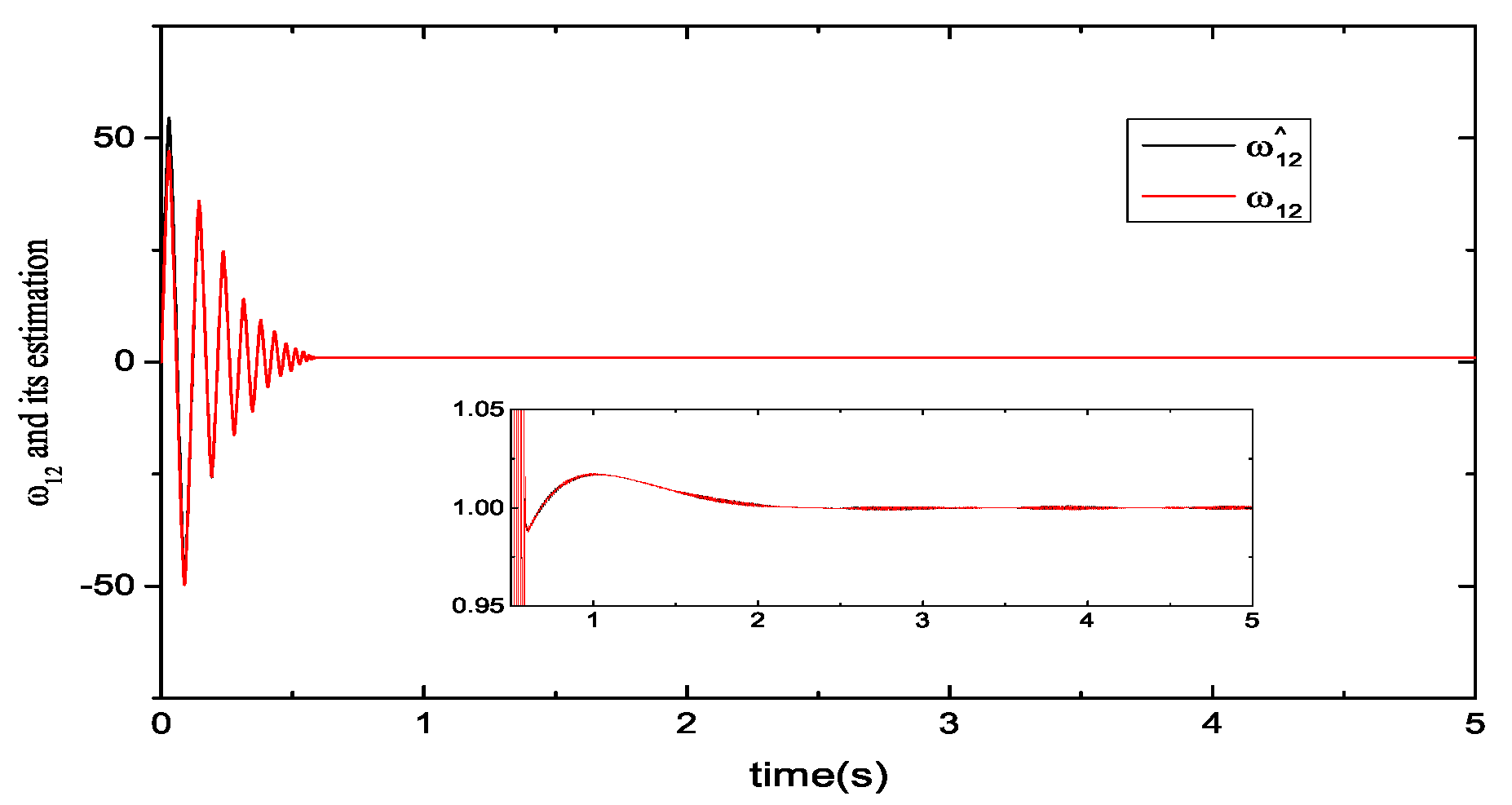
In addition, the accuracy of state estimation also has an important impact on the performance of the controller. Figure 6, Figure 7, Figure 8 and Figure 9 show the comparison of the unmeasurable states and their corresponding estimated values of four subsystems. In Figure 6, it shows that the unmeasurable state value ω 1 and its corresponding estimated value achieve consensus tracking after 0.25 s and the maximum steady-state error ratio of the observer is 0.342%. Similarly, from Figure 7, Figure 8 and Figure 9, it can be concluded that the maximum tracking time of the observers is 0.3 s, 0.28 s, and 0.3 s, respectively. The maximum steady-state error ratios of all the observers are 0.342%, 0.425%, 0.613%, and 0.532%, which satisfy the requirements of the controller design.

5.2. Performance Evaluations of the Consensus Control Protocol

Two cases are provided to verify the synchronous control performance of all motors under the consensus control protocol.
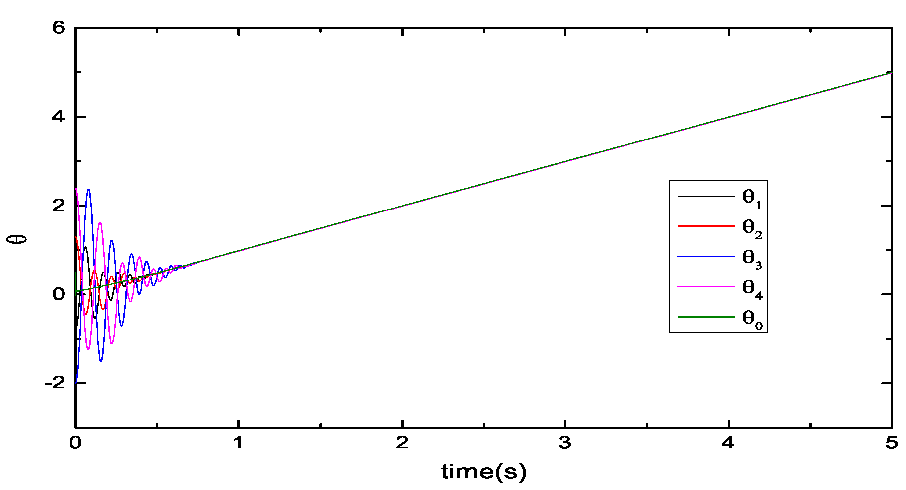
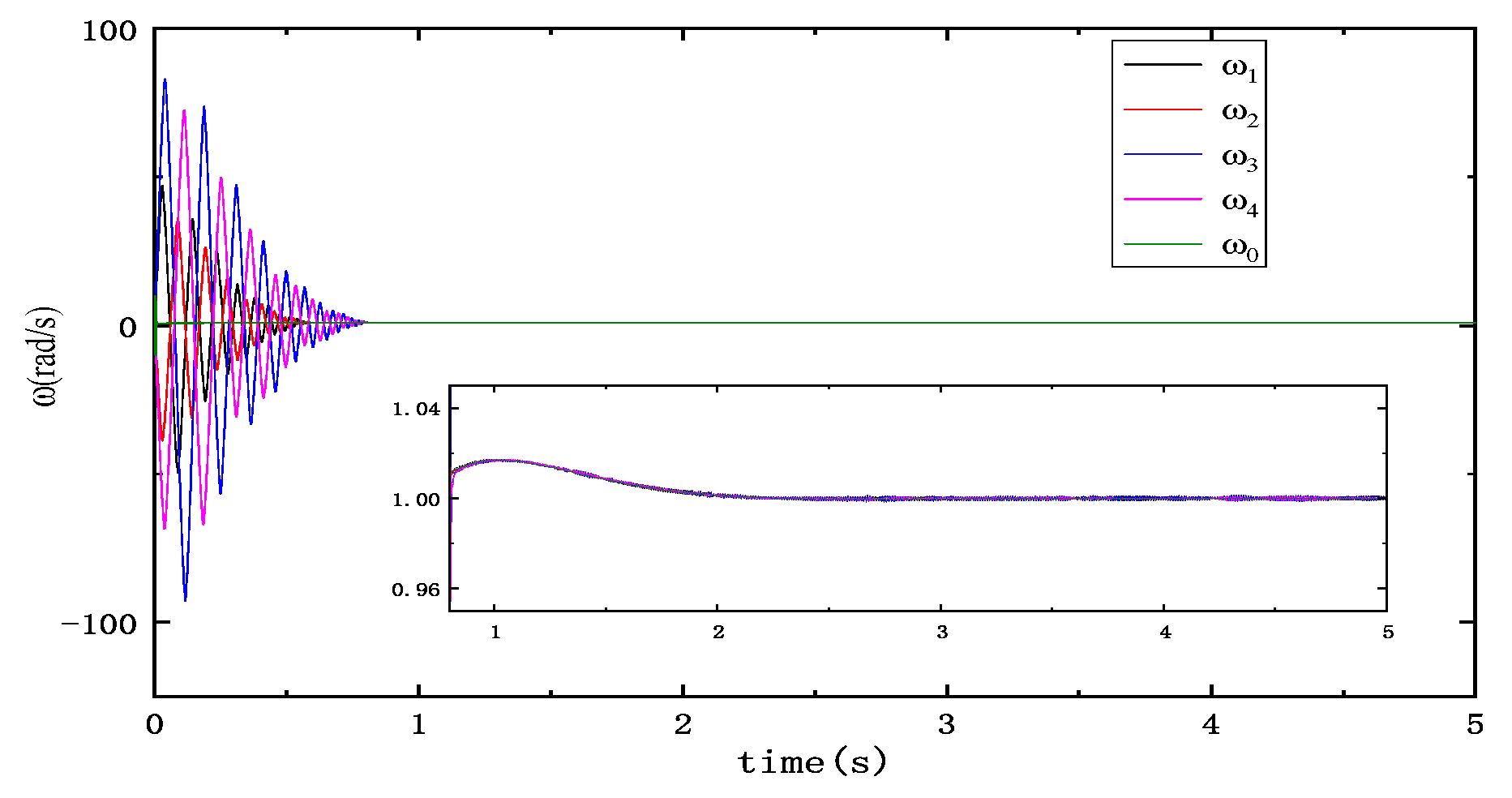
Case 1: The leader’s output is a ramp function θ 0 = t ( r a d ) . Figure 10 and Figure 11 show the dynamic tracks of the positions and velocities of all motors under the consensus protocol. The output curves of the follower motors 1, 2, 3, and 4 are marked by solid black, solid red, solid blue, and solid pink lines, respectively. As shown in Figure 10 and Figure 11, the output amplitudes of all following motors are showing a decreasing trend before 0.65 s. Figure 10 shows that the four following motors track the position signal of the virtual leader motor. The simulation result indicates that the positions of the motors in the system tend to be consistent after approximately 0.65 s. Figure 11 shows that the speed signals of the followers are gradually consistent with the speed of the virtual leader, which converge to 1 rad/s by theoretical calculation. The maximum steady-state error ratio of case 1 is 0.25%.
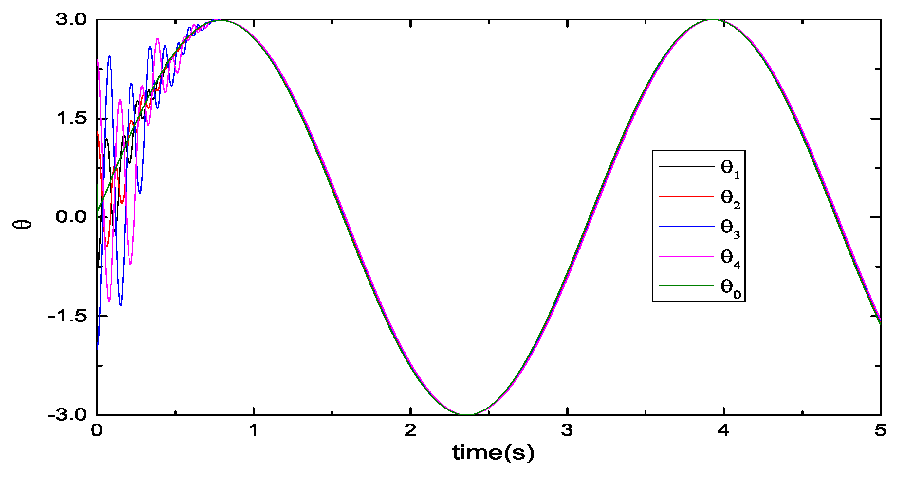
Case 2: The leader’s output is a sinusoidal signal θ 0 = 3 sin ( 2 t ) . Figure 12 and Figure 13 show the position and velocity signals of all motors under the consensus protocol. As shown in Figure 12 and Figure 13, the output amplitudes of all following motors show a decreasing trend and are gradually approaching the output amplitude of the leader motor before 0.61 s. Figure 12 shows that the four following motors track the position signal of the virtual leader motor under the reference signal θ 0 = 3 sin ( 2 t ) . The simulation result indicates that the positions of the motors in the system tend to be consistent after approximately 0.61 s. Figure 13 shows that the speed signals of the followers are gradually consistent with the speed of the virtual leader, and the maximum steady-state error ratio of case 2 is 0.752%. Based on the simulation results of case 1 and case 2, it is clear that the positions and speed of all motors reach consensus with the leader in finite time. In short, the proposed control method can effectively suppress the influence of chattering and uncertainties such as unknown compound disturbances and parameter perturbation on the multi-motor system.
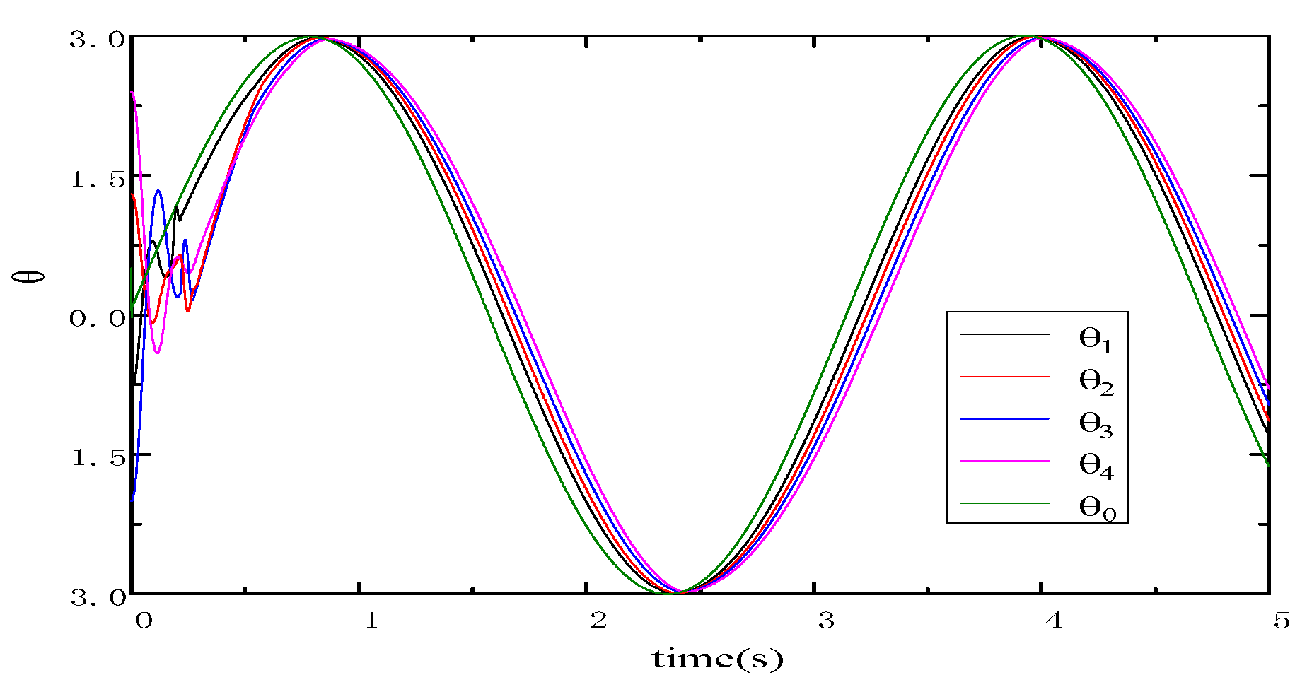
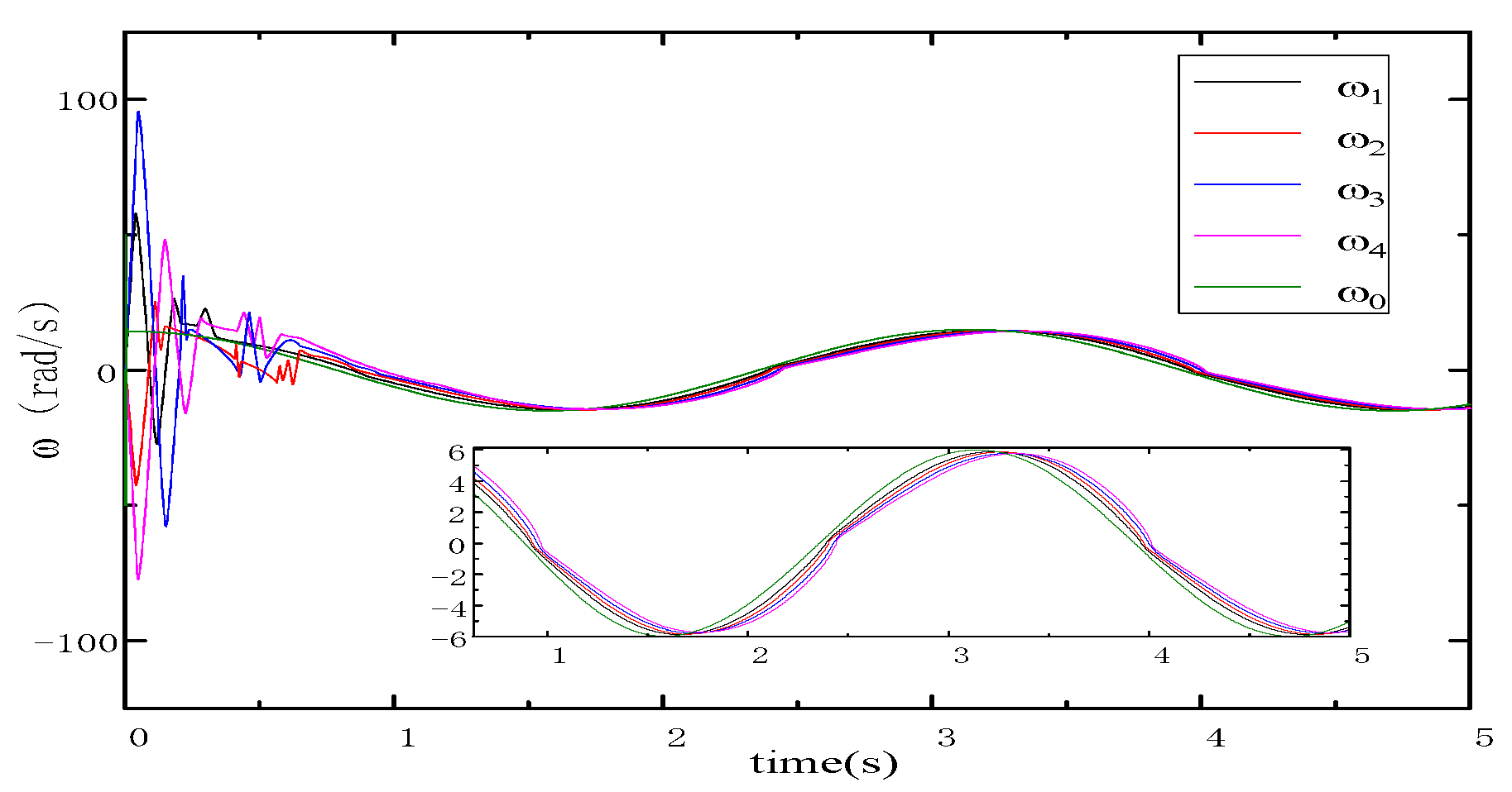
To illustrate the advantage of the proposed control method, a comparison result will be presented by applying the consensus tracking control protocol in the reference [22]. The identical initial states, parameters of the control law and uncertainties are selected the same to ensure the fairness of the comparison. Figure 14 shows that the four following motors track the position signal of the virtual leader motor and Figure 15 shows that the speed signals of the followers are gradually consistent with the speed of the virtual leader. As shown in Figure 14 and Figure 15, the four following motors gradually converge after t = 0.58 s. It is obvious that although the convergence time in Figure 14 and Figure 15 is slightly shorter than that in Figure 12 and Figure 13, the final consensus tracking accuracy in Figure 14 and Figure 15 is obviously worse than that in Figure 12 and Figure 13 under the same simulation conditions. The results further show that the proposed control method has greater advantages in consistency tracking accuracy and robustness.

6. Conclusions

In this study, the multi-motor synchronous control was examined under the framework of finite-time leader–follower consensus with speed sensorless. We have designed a finite-time consensus tracking protocol based on the output feedback to solve the unknown composite disturbance and overcome the difficulty in obtaining speed signals. At the same time, the proposed control method only requires less information interaction and effectively suppresses chattering. The adverse effect of the observer error on the cooperative tracking performance is considered during the stability analysis. Using Lyapunov and graph theory, it is proven that the consensus tracking error converges to an arbitrary small neighborhood of zero in finite time. Under the dual constraints of four common interference signals and unknown speed signals, the finite-time observer can accurately estimate the unknown interference and undetectable states. A multi-agent system consisting of five motors is used as the simulation object. Simulations are provided to corroborate that the proposed consensus control protocol exhibits high synchronization performance and robustness. In fact, as long as appropriate parameters are set, the position and speed of the followers are consistent with the leader under any required reference value. For future work, it is recommended to consider a multi-agent system with dynamic topologies and time-delayed control from neighbors. We aim to further extend the proposed second-order multi-agent system to higher-order or general systems with the unknown interference and states.

Author Contributions

B.Z. and S.M. conceived and designed the experiments; B.Z., H.Z. and T.Q. performed the experiments and analyzed the data; B.Z. and Y.Z. contributed to the paper structure and framework design; B.Z. and S.M. wrote the paper. All authors have read and agreed to the published version of the manuscript.

Funding

This work has been partially supported by the National Natural Science Foundation of China under Grant 62103152, the Strategic Priority Research Program of the Chinese Academy of Sciences (class A) (Grant No. XDA22040203), the Natural Science Foundation of Guangdong Province (Grant No. 2020A1515010621), and Guangzhou Applied Basic Research Foundation (202102020360).

Institutional Review Board Statement

Not applicable.

Informed Consent Statement

Not applicable.

Data Availability Statement

No data is reported in the article.

Acknowledgments

The authors would like to express their sincere gratitude to all our respective reviewers and editors for their pertinent and constructive comments.

Conflicts of Interest

The authors declare that they have no known competing financial interest or personal relationships that could have appeared to influence the work reported in this paper.

References

  1. Wang, M.; Ren, X.; Chen, Q. Robust tracking and distributed synchronization control of a multi-motor servomechanism with H-infinity performance. ISA Trans. 2018, 72, 147–160. [Google Scholar] [CrossRef] [PubMed]
  2. Hu, S.; Ren, X.; Lv, Y. Predictor-Based Tracking and Synchronization Control for Multi-Motor Drive Servo Systems. In Proceedings of the 2019 IEEE 8th Data Driven Control and Learning Systems Conference (DDCLS), Dali, China, 24–27 May 2019; Volume 1, pp. 539–544. [Google Scholar]
  3. Canese, L.; Cardarilli, G.C.; Nunzio, L.D.; Fazzolari, R.; Giardino, D.; Re, M.; Spanò, S. Multi-Agent Reinforcement Learning: A Review of Challenges and Applications. Appl. Sci. 2021, 11, 4948. [Google Scholar] [CrossRef]
  4. Fang, P.; Wang, Y.; Hou, Y.; Wu, Y.F. Synchronous Control of Multi-Motor Coupled with Pendulum in a Vibration System. IEEE Access 2020, 8, 51964–51975. [Google Scholar] [CrossRef]
  5. Masroor, S.; Peng, C. Agent-based consensus on speed in the network-coupled DC motors. Neural Comput. Appl. 2016, 30, 1647–1659. [Google Scholar] [CrossRef]
  6. Amornwongpeeti, S.; Ekpanyapong, M.; Chayopitak, N.; Monteiro, J. A single chip FPGA-based cross-coupling multi-motor drive system. IEICE Electron. Express 2015, 12, 383–389. [Google Scholar] [CrossRef] [Green Version]
  7. Chen, B.; Ding, J. Adaptive Model-Free Coupling Controller Design for Multi-Axis Motion Systems. Appl. Sci. 2020, 10, 3592. [Google Scholar] [CrossRef]
  8. He, J.; Ding, J.; Zhang, C.; Mao, S.; Liu, J.; Hu, J.; Ma, Z. Research on Multi-axis Servo Synergic Control System Based on Sliding Mode Variable Structure. In Proceedings of the IECON 2019—45th Annual Conference of the IEEE Industrial Electronics Society, Lisbon, Portugal, 14–17 October 2019; Voluem 1, pp. 6908–6915. [Google Scholar]
  9. Koren, Y. Cross-Coupled Biaxial Computer Control for Manufacturing Systems. J. Dyn. Syst. Meas. Control.-Trans. Asme 1980, 102, 265–272. [Google Scholar] [CrossRef]
  10. Shuang, B.; Zhu, Z.Q.; Wu, X. Improved Cross-coupling Effect Compensation Method for Sensorless Control of IPMSM with High Frequency Voltage Injection. IEEE Trans. Energy Convers. 2022, 37, 347–358. [Google Scholar] [CrossRef]
  11. Zhu, C.; Tu, Q.; Jiang, C. A Cross Coupling Control Strategy for Dual-Motor Speed Synchronous System Based on Second Order Global Fast Terminal Sliding Mode Control. IEEE Access 2020, 8, 217967–217976. [Google Scholar] [CrossRef]
  12. Chen, W.; Liang, J.; Shi, T. Speed Synchronous Control of Multiple Permanent Magnet Synchronous Motors Based on an Improved Cross-Coupling Structure. Energies 2018, 11, 282. [Google Scholar] [CrossRef] [Green Version]
  13. Li, L.; Sun, L.; Zhang, S. Mean deviation coupling synchronous control for multiple motors via second-order adaptive sliding mode control. ISA Trans. 2016, 62, 222–235. [Google Scholar] [CrossRef] [PubMed]
  14. Shi, T.; Liu, H.; Geng, Q.; Xia, C. Improved relative coupling control structure for multi-motor speed synchronous driving system. Iet Electr. Power Appl. 2016, 10, 451–457. [Google Scholar] [CrossRef]
  15. Štil, V.J.; Varga, T.; Benšić, T.; Barukčić, M. A Survey of Fuzzy Algorithms Used in Multi-Motor Systems Control. Electronics 2020, 9, 1788. [Google Scholar] [CrossRef]
  16. Li, L.; Sun, L.; Zhang, S.; Yang, Q. Speed tracking and synchronization of multiple motors using ring coupling control and adaptive sliding mode control. ISA Trans. 2015, 58, 635–649. [Google Scholar] [CrossRef]
  17. Yu, S.; Long, X. Finite-time consensus for second-order multi-agent systems with disturbances by integral sliding mode. Automatica 2015, 54, 158–165. [Google Scholar] [CrossRef]
  18. Zhang, C.; Lin, Z.; Yang, S.X.; He, J. Total-Amount Synchronous Control Based on Terminal Sliding-Mode Control. IEEE Access 2017, 5, 5436–5444. [Google Scholar] [CrossRef]
  19. Koren, Y. Distributed finite-time tracking of multiple non-identical second-order nonlinear systems with settling time estimation. Automatic 2016, 64, 86–93. [Google Scholar]
  20. Amornwongpeeti, S.; Ekpanyapong, M.; Chayopitak, N.; Monteiro, J. Finite-time consensus for second-order multi-agent systems with saturated control protocols. IET Control Theory Appl. 2015, 9, 312–319. [Google Scholar]
  21. Ma, X.; Sun, F.; Li, H.; He, B. Neural-network-based integral sliding-mode tracking control of second-order multi-agent systems with unmatched disturbances and completely unknown dynamics. Int. J. Control Autom. Syst. 2017, 15, 1925–1935. [Google Scholar] [CrossRef]
  22. Zhang, C.; Wu, H.; He, J.; Xu, C. Consensus tracking for multi-motor system via observer based variable structure approach. J. Frankl. Inst. 2015, 352, 3366–3377. [Google Scholar] [CrossRef]
  23. Zhang, C.; Lin, Z.; Liu, J.; He, J.; Wu, H.; Li, P. Consensus-based total-amount cooperative tracking control for multi-motor locomotive traction system. J. Frankl. Inst. 2019, 356, 819–834. [Google Scholar] [CrossRef]
  24. Zhang, C.; Wu, H.; Liu, B.; He, J.; Li, B. Hybrid Structure Based Tracking and Consensus for Multiple Motors. Math. Probl. Eng. 2014, 2, 1–9. [Google Scholar] [CrossRef] [Green Version]
  25. Zhou, B.; Xu, C.; Duan, G. Distributed and Truncated Reduced-Order Observer Based Output Feedback Consensus of Multi-Agent Systems. IEEE Trans. Autom. Control 2014, 59, 2264–2270. [Google Scholar] [CrossRef]
  26. Li, G.; Wang, X.; Li, S. Finite-Time Output Consensus of Higher-Order Multiagent Systems With Mismatched Disturbances and Unknown State Elements. IEEE Trans. Syst. Man Cybern. Syst. 2019, 49, 2571–2581. [Google Scholar] [CrossRef]
  27. Chen, W.-H.; Ding, K.; Lu, X. Disturbance-observer-based control design for a class of uncertain systems with intermittent measurement. J. Frankl. Inst. 2017, 354, 5266–5279. [Google Scholar] [CrossRef]
  28. Chen, W.-H.; Cheng, L.; Lu, X. Observer-based feedback stabilization of Lipschitz nonlinear systems in the presence of asynchronous sampling and scheduling protocols. Nonlinear Anal. Hybrid Syst. 2019, 33, 282–299. [Google Scholar] [CrossRef]
  29. Chen, W.-H.; He, H.; Lu, X.; Deng, X. Impulsive observer-based design for state estimation of a class of nonlinear singularly perturbed systems with discrete measurements. Nonlinear Anal. Hybrid Syst. 2021, 41, 101–117. [Google Scholar] [CrossRef]
  30. Chen, S.; Liu, G.; Zhu, L. Sensorless Control Strategy of a 315 kW High-Speed BLDC Motor Based on a Speed-Independent Flux Linkage Function. IEEE Trans. Ind. Electron. 2017, 64, 8607–8617. [Google Scholar] [CrossRef]
  31. Jakobsen, U.; Lu, K.; Rasmussen, P.O.; Lee, D.; Ahn, J. Sensorless Control of Low-Cost Single-Phase Hybrid Switched Reluctance Motor Drive. IEEE Trans. Ind. Appl. 2015, 51, 2381–2387. [Google Scholar] [CrossRef]
  32. Xiao, D.; Nalakath, S.; Filho, S.R.; Fang, G.; Dong, A. Universal Full-Speed Sensorless Control Scheme for Interior Permanent Magnet Synchronous Motors. IEEE Trans. Power Electron. 2021, 36, 4723–4737. [Google Scholar] [CrossRef]
  33. Chen, J.; Huang, J.; Sun, Y. Resistances and Speed Estimation in Sensorless Induction Motor Drives Using a Model with Known Regressors. IEEE Trans. Ind. Electron. 2019, 66, 2659–2667. [Google Scholar] [CrossRef]
  34. Ren, Y.; Wang, R.; Rind, S.J.; Zeng, P.; Jiang, L. Speed sensorless nonlinear adaptive control of induction motor using combined speed and perturbation observer. Control Eng. Pract. 2022, 1, 105–119. [Google Scholar] [CrossRef]
  35. Abadi, A.S.S.; Hosseinabadi, P.A.; Mekhilef, S. Fuzzy Adaptive Fixed-time Sliding Mode Control with State Observer for A Class of High-order Mismatched Uncertain Systems. Int. J. Control Autom. Syst. 2020, 3, 1–17. [Google Scholar] [CrossRef]
  36. Wang, Y.; Song, Y.; Krstić, M.; Wen, C. Adaptive finite time coordinated consensus for high-order multi-agent systems: Adjustable fraction power feedback approach. Inf. Sci. 2016, 372, 392–406. [Google Scholar] [CrossRef]
  37. Mo, S.; Chen, W.; Lu, X. Distributed hybrid secondary control strategy for DC microgrid group based on multi-agent system. In Proceedings of the 2021 33rd Chinese Control and Decision Conference (CCDC), Kunming, China, 22–24 May 2021; Volume 1, pp. 109–114. [Google Scholar]
  38. Marshall, A.W.; Olkin, I.; Arnold, B.C. Inequalities: Theory of Majorization and Its Applications; Springer: Berlin/Heidelberg, Germany, 1980; Volume 146. [Google Scholar]
  39. Aung, W.P. Analysis on Modeling and Simulink of DC Motor and its Driving System Used for Wheeled Mobile Robot. Int. J. Electr. Comput. Energ. Electron. Commun. Eng. 2007, 1, 1141–1148. [Google Scholar]
Figure 1. Topology structural diagram of the interaction between motors.
Applsci 12 05518 g001
Figure 2. Performance evaluation curves for four unknown disturbance observers: disturbance of motor 1 and its estimated value.
Applsci 12 05518 g002
Figure 3. Performance evaluation curves for four unknown disturbance observers: disturbance of motor 2 and its estimated value.
Applsci 12 05518 g003
Figure 4. Performance evaluation curves for four unknown disturbance observers: disturbance of motor 3 and its estimated value.
Applsci 12 05518 g004
Figure 5. Performance evaluation curves for four unknown disturbance observers: disturbance of motor 4 and its estimated value.
Applsci 12 05518 g005
Figure 6. Estimated performance evaluation curves of four motor velocities: velocity ω 1 and its estimated value curve.
Applsci 12 05518 g006
Figure 7. Estimated performance evaluation curves of four motor velocities: velocity ω 2 and its estimated value curve.
Applsci 12 05518 g007
Figure 8. Estimated performance evaluation curves of four motor velocities: velocity ω 3 and its estimated value curve.
Applsci 12 05518 g008
Figure 9. Estimated performance evaluation curves of four motor velocities: velocity ω 4 and its estimated value curve.
Applsci 12 05518 g009
Figure 10. Consensus dynamic tracking curve of all motors under the reference signal θ 0 = t ( r a d ) : position signals of all motors.
Applsci 12 05518 g010
Figure 11. Consensus dynamic tracking curve of all motors under the reference signal θ 0 = t ( r a d ) : velocity signals of all motors.
Applsci 12 05518 g011
Figure 12. Consensus dynamic tracking curve of all motors under the reference signal θ 0 = 3 sin ( 2 t ) : position signals of all motors.
Applsci 12 05518 g012
Figure 13. Consensus dynamic tracking curve of all motors under the reference signal θ 0 = 3 sin ( 2 t ) : velocity signals of all motors.
Applsci 12 05518 g013
Figure 14. Compared with the consensus tracking protocol proposed in the reference [22], all motor tracking curves under the same simulation conditions: position signals of all motors.
Applsci 12 05518 g014
Figure 15. Compared with the consensus tracking protocol proposed in the reference [22], all motor tracking curves under the same simulation conditions: velocity signals of all motors.
Applsci 12 05518 g015
Table 1. Parameter settings of all motors.
Motor R ( Ω ) J eq (kg · m2) k e (mv/rad/s) k t Initial Value θ (0) (Rad)
00.20.0250.120.0060.5
10.60.0350.240.012−0.8
20.50.030.240.0091.3
30.70.060.250.018−2.1
40.80.040.30.022.5
Publisher’s Note: MDPI stays neutral with regard to jurisdictional claims in published maps and institutional affiliations.