1. Introduction
Robotic inspection and path planning procedures are well defined for parts with accurate digital twins, enabling automatic path extraction [
1]. This condition is not necessarily met in a range of industries such as remanufacturing, moulded part manufacturing or autonomous site inspection in hazardous environments.
The wear of parts in remanufacturing, or non-critical warping of parts in moulded-part manufacturing such as spring-back [
2] means that the part does not necessarily match the available CAD model. For legacy parts or the inspection of free-form surfaces autonomously, there may be no CAD model available for path planning.
The authors have sought to address the issue of unseen simultaneous autonomous surface profiling and scanning with the Complete-Surface-Finding-Algorithm (CSFA) within [
3]. The CSFA has succeeded in creating a criteria to search an entire surface and in defining a criterion that specifies completion. For surfaces of significant complexity such as struts and other extrusions, additional environmental information may be necessary to detect and prevent collisions.
In this work, a low-cost RGB/Depth camera is utilised for a pre-scan in order to gain a rough model of the part. Both 2D and 3D imaging with RGB and RGB/D cameras are becoming prevalent within NDT. Despite this, many issues with map reconstruction still prove to be a critical block to more general usage within robotised NDT.
An initial study of 2D Visual Odometry and part mosaicing [
4] highlighted several drawbacks with visual imaging and NDT. The key block to wide-spread usage is that highly specular surfaces such as polished metal produce significant visual artefacts. For sectors such as remanufacturing and aerospace that rely on polished metal or highly reflective Carbon-Fibre Reinforced Polymer (CFRP) samples, this is a critical issue. A related work found that a robotically applied Structure-from-Motion (SfM) schema could reproduce parts with sub-millimetre accuracy once the point clouds had been processed [
5]. Key to this method is the presence of significant visual artefacts on the part, allowing dense point-cloud extraction from subsequent 2D images taken at known positions. These studies have presented significant improvements in reverse engineering of parts for later NDT scanning. However, the scans taken for these parts are completed by two complex robotic procedures that are operator-specified. The operator must input a path that is known not to either collide with the part or meet kinematic singularities, and is entirely reachable by the robot. In order to construct a dense 3D map of the part, the data threshold is high, requiring hundreds of images with up to
image overlap to ensure proper part-reconstruction. This presents the significant disadvantage of requiring the part to be stationary within the cell while camera and UT probe tools are interchanged, since the derived CAD model is localised with respect to the robotic work-space.
Small one-shot surface profiling systems such as RGB/D or LIDAR cameras present solutions to this problem, able to profile the surface with the UT probe attached. Several autonomous robotic arm [
6,
7] and drone based [
8] NDT scanning methods rely on this approach. The key drawback of these deployments are the reliance on primitives such as cylinders and planes, reducing flexibility when faced with complex, warped or unknown surfaces. The authors have used the raw point cloud data from off-the-shelf RGB/D cameras to construct paths over the surface, complimented by online path corrections during the UT scan.
Force control is used to ensure the UT probe maintains constant contact with the part through path corrections. Force data in the context of robotic UT-NDT have traditionally utilised roller probe technology, used to provide local corrections to the estimated position of a known part within the robot’s frame of references [
9,
10,
11]. These examples have, however, used known digital-twin models with limited positioning corrections required.
The main draw-back of roller probes are the uni-directional speed allowed along the tool’s axis, along with shear forces causing degradation of the roller probe’s polymer components. An alternative UT contact measurement device is the Conformable Wedge (CW) probe. Filled with water, the wedge’s material has a near-identical UT wave-speed as water, preventing reflection at the boundary. The main drawback of conformable wedges used within a force control schema is the potential for bursting. This method is not suitable for sharp surfaces or high forces, which is defined dependant on the probe material and thickness.
While CW probes are more sensitive to sharp corners than roller probes, the nearly-flat aperture of the sensor presents the advantage of additional information in the form of surface friction. Corroded parts prevalent within sectors such as remanufacturing require surface pre-preparation to clean and level rusted patches in accordance with ISO standard 16809:2017 [
12]. In certain regions, operators may have insufficiently prepared the surface, or the surface thickness may not allow levelling. In these cases, surface roughness data are advantageous to map overlooked regions of the surface in the preparation stage. While laser data provides high-accuracy surface position feedback, the couplant fills pits on the surface, presenting it as smooth and preventing it from providing such a metric. For conformable and flat rigid surfaces separated by a thin film of fluid, the frictional force is a sum of the hydrodynamic friction due to viscosity, and the asperity or contact force [
13]. The hydrodynamic friction term
, contact load
P, area of the CW probe
A, contact friction term
, and normal force
F define the dimensionless coefficient of friction
in a mixed-lubrication regime;
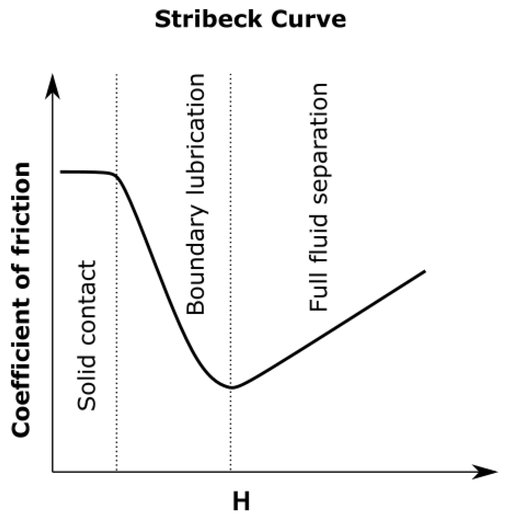
Contributions of hydrodynamic and contact friction are proportional to the surface area exposed to each regime. Along the Stribeck curve [
14], the hydrodynamic coefficient of friction is related in a highly non-linear way with the average load
P, wedge/couplant relative speed
v, and fluid viscosity
by the Hersey number
. The Stribeck curve is shown in
Figure 1.
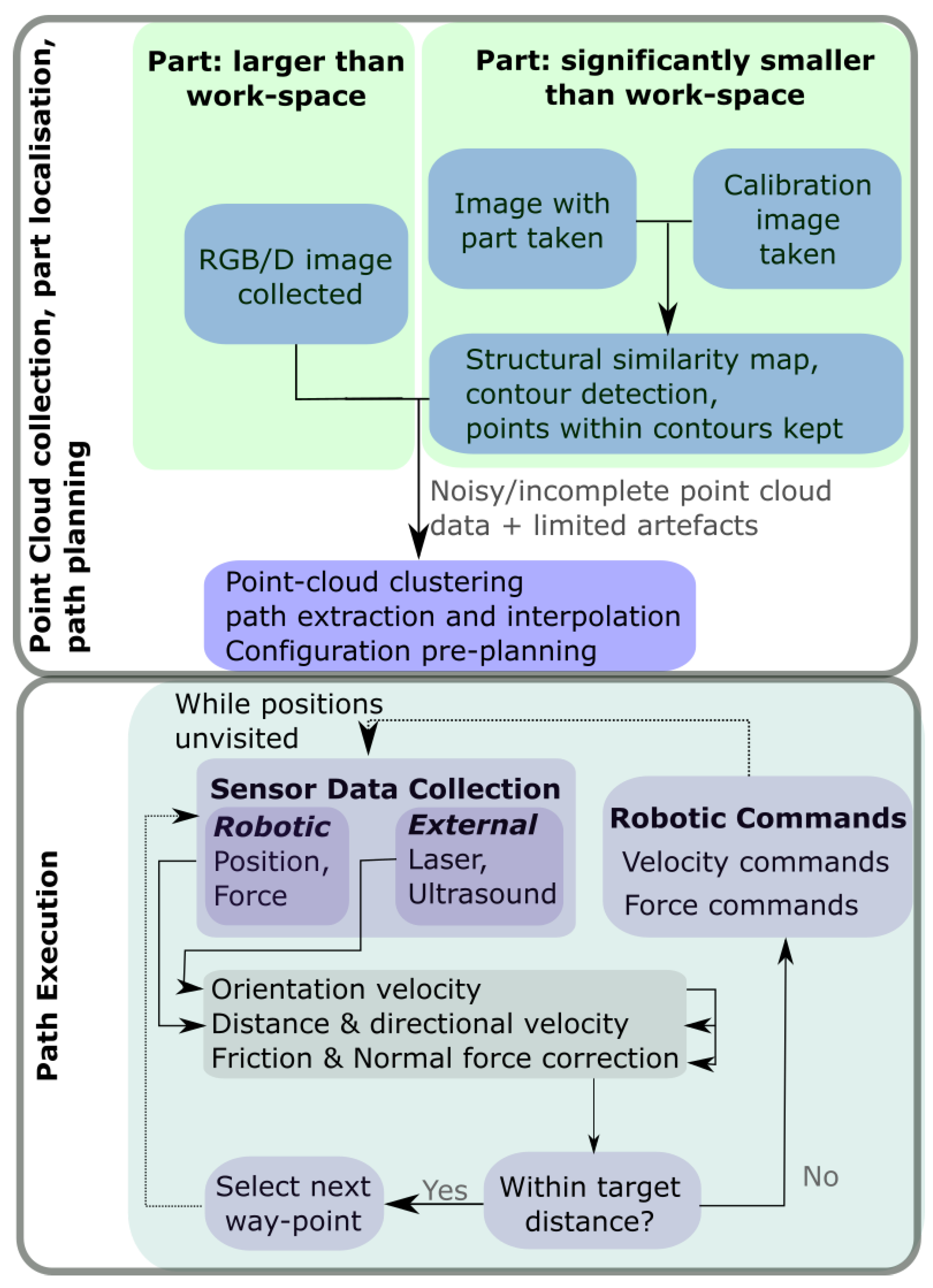
This paper has sought to introduce an autonomous scanning procedure that address the issues with moulded part manufacturing and remanufacturing industries where an accurate digital twin is not always available. The presented method autonomously plans paths and deploys a UT sensor without prior knowledge of the surface through:
location of and planning over a surface using a noisy and incomplete representation of the surface,
simultaneous UT probe alignment, scanning, and path corrections using local force and laser-sensor feedback.
The novel path planning method presented overcomes limitations of traditional visual systems such as variable-lighting artefacts [
15] and RGB/D specific artefacts [
16] without the need for complex and potentially inaccurate point cloud corrections. Further, the requirement for apriori knowledge of the surface, such as imposed primitives, are removed. This is completed while taking full advantage of the data available to minimise the risk of collisions in-process.
The presented method enables single-shot part localisation strategies that could not be used under previous vision-enabled path planning regimes that require greater levels of accuracy. The novel method of robotic force control with a conformable wedge probe has also been demonstrated to offer additional information unavailable to roller or UT probes in the form of surface friction measurements. The full path planning execution process proposed is presented in
Figure 2.
The paper is laid out as follows.
Section 2 covers the algorithms used to localise and then plan paths over a point cloud representation of the part.
Section 3 then applies this path to the robot, describing how the best collision-free path over and approach to the part is calculated in robotic configuration coordinates.
Section 4 then provides details of how the initial path plan is locally corrected online with sensor and internal robotic readings. the method of surface reconstruction and data visualisation is then covered in
Section 5 to aid in operator interpretation of UT results. Finally, experimental results that display the efficacy of each section of the pipeline are presented in
Section 6.
2. Surface Localisation and Profiling
Structured light systems emit low-powered Infra-Red (IR) light that are reflected by objects and received by at least two cameras. The combined observations of the projected pattern are used to triangulate and calculate a depth map in the camera’s field of view. The key disadvantage of these systems is their sensitivity to ambient light and surface reflectivity. Ambient lighting conditions with wide band-width rays, such as direct sunlight, can hide and distort the projected pattern observed by the RGB/D camera system. For highly reflective surfaces, sections of the part may be missing or suffer significant noise as a result.
Applying traditional robotic-NDT path-planning methods to RGB/D point clouds requires surface position and normal estimation for each of the visited points, so as to align the tool correctly. However, even minor point cloud distortions can effect the numerical accuracy of the extracted vector. An advantage of RGB/D cameras is the ability to apply traditional computer-vision techniques to the point cloud map attained. In segmenting parts, two approaches were used for parts of varying scale. For parts smaller than the field of view of the camera, an initial image of the cell and a subsequent image were used in combination with the structural-similarity indices of the two colour images to locate the part. For larger parts, clustering of points to find the nearest point cloud were used to identify the part.
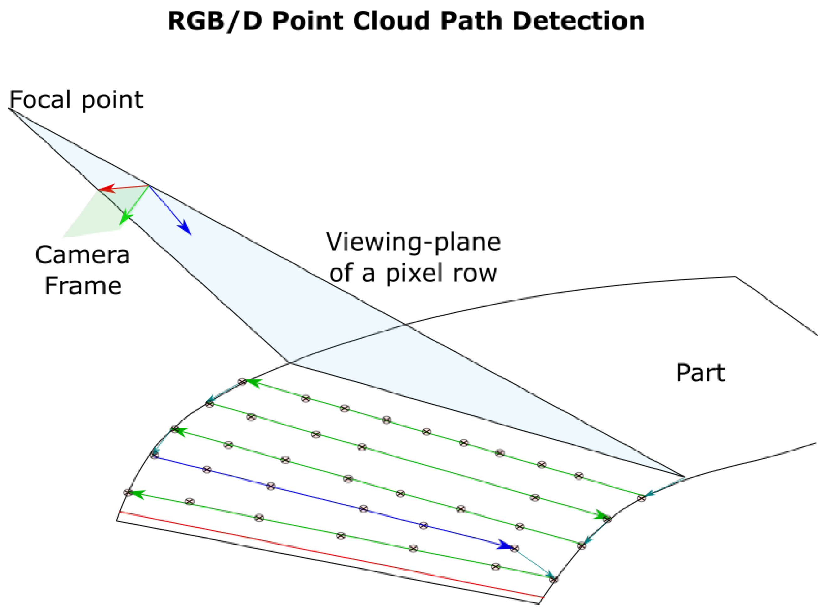
Once the part’s point cloud position is attained and normals are approximated, a rough path for the robot to follow is extracted from the camera’s inherent rasterisation, shown in
Figure 3. Though the RGB/D camera is composed of two cameras, their co-planarity allows the field to view to be merged and simplified to a single camera’s. Excess information within the point cloud has then been utilised as environmental information to detect collisions.
An additional method implemented for guided scanning enables the operator to select a bounding polygon on the colour image, specifying a scanning region. A path is planned on the points within the polygon on the colour and depth maps.
3. Robotic Path Pre-Planning
Environmental data from the RGB/D cameras can inform the process of a potential collision due to a given robotic motion. Since the robot is controlled with speed commands on an uncertain surface, collision detection and prevention is completed before the scan takes place. A custom CUDA-kernel was written to check whether the rough path taken by the robot is collision free, and to remove way-points that may cause a collision given their estimated normals and position. The environmental data consists of the whole point cloud of the part and cell that is then separately refined for path planning, as well as a bounding box set to prevent collisions with the cell. The process of this function is documented in Algorithm 1.
| Algorithm 1: Calculate possible collision-free paths, and the cost of each path from each potential initial configuration. |
| for Path do |
| † |
| end for |
| for, Path do |
| † |
| |
| end for |
| fordo |
| , |
| while do |
| if then |
| |
| |
| |
| |
| else |
| |
| end if |
| end while |
| end for |
Then either the closest initial configuration to the current one can then be used, the one which will lead to the longest collision-free path (given by ’GenCount’ in Algorithm 1, or the one that will lead to the shortest distance travelled in configuration-space depending on operator preference.
After an initial configuration is decided, the approach is calculated using linear motion in the configuration space. If a collision is found, then a Rapidly-exploring Random Tree (RRT) framework calculates a collision free path from the current to the starting configurations.
The limitations of this pre-scan method is that the uncertainty in the point-cloud position and orientation may lead to positions being removed without causing a collision in process. However, the speed command control method requires regular updates, rendering an in-process collision detection method for an unknown surface unfeasible due to latency.
4. Local Robotic Corrections
Once the rough surface has been profiled and localised, the robot needs to traverse the surface. Due to hardware and numerical limitations, real-time path corrections are provided from auxiliary sensors.
The point cloud’s inaccuracies and coupling method of the conformable wedge probe require the conditions:
initial coupling to the surface from the erroneous point cloud;
traversal method that keeps the sensor probe in contact with the surface;
direction commands for the robotic platform to visit each way-point in the path that also compensate for positioning errors;
stop conditions when visiting each way-point.
The Universal-Robot’s UR10e platform deployed comes equipped with force-torque control, enabling the robot to move in a given direction until a force is felt. By utilising the first point’s normal estimation, the robot is able to couple to the surface satisfying Condition: 1.
The Universal Robot’s force control mode also allows users to set directed forces and admissible deviations while executing a path. By requiring the robot apply a set force in the tool’s z-direction and allowing deviations in the works-space dimension that composes the majority of the current tool’s z direction, the robot was able to maintain contact with the part. Allowing motion in all cardinal directions resulted in undesirable motion, requiring the restriction to the direction that gave the largest contribution.
The robotic paths were executed by setting the Cartesian and rotational directions of the tool’s target velocity, within a control loop. While a directed point or planar force/torque sensor has the capability to correct for orientation deviations, the conformable wedge probe presented a non-planar surface that allowed the robot to slip into misalignment.
To aid in the high-accuracy reconstruction of the surface, three linear laser sensors were rigidly attached to the flange. In addition to providing high-accuracy surface positions, the live measurements provided on-line orientation corrections. The laser-measurements provide the approximated surface orientation given by a
rotation matrix
within the world-frame, while the robot has current rotation
. Universal robots utilise the
convention, with the required orientation correction given by;
where
is the conversion between twist vectors and
group elements [
17]. The angular difference is converted to angular velocity
using the average
and standard deviation
of previous loop-durations,
. The damping factor is used to prevent over-corrections and loss of contact with the surface with variable loop speeds and geometric factors.
While the force kept the tool coupled to the part, and the lasers kept the tool normal to the part satisfying Condition 2, data obtained by the RGB/D camera set the directional speed values .
Given a rough target position , current robotic position , current flange orientation matrix , and target tcp speed s, the values were calculated.
Taking the projection to the surface’s tangent plane;
and scaling this to the desired velocity;
. When the remaining in-plane distance from the target is small enough that the robot would over-shoot in a control-loop cycle, the speed is reduced to the estimated value. This satisfies Condition: 3. The projection is necessary since point cloud errors along the surface normal result in jerky motion, with the velocity vector set away from the target surface while the robot tries to maintain a constant force against the surface.
Finally, the stop condition for the robot at each way-point is summarised by taking the current tool position
, velocity vector
, and way point
. The distance
q of the robot from the way-point in the plane is;
Once q has reached a threshold value, the robot is considered to have reached the desired way-point, satisfying Condition: 4.
This method is only suitable for point cloud representation of surfaces that fulfil the following condition: (a) there is a curve along the surface that intersects the current and next way-points such that , and (b) the global minima of the parameter q is attained at only one point along this curve. Point cloud representations of surfaces that do not follow this can only allow sub-optimal solutions to the path followed, or no solutions at all.
This process does assume that each point within the point cloud represents the closest position on the surface. This increases the accuracy threshold for suitable RGB/D sensors when applied to surfaces of high-curvature. For a surface with maximum normal curvature , the maximal inaccuracy can be with .
The speed control for the robot is summarised in Algorithm 2.
| Algorithm 2: Speed control algorithm applied to reach each control point. |
| Define acceptable stopping radius r and expected speed s. |
| for Path do |
| , |
| , , |
| while do |
| , |
| , |
| if ==3 then |
| Extract surface orientation matrix: , |
| else |
| Assert the current TCP orientation is the surface’s; |
| end if |
| Project vector difference to surface tangent: , |
| Update distance value: , |
| Moderate speed with average loop-time so far; . |
| end while |
| end for |
Since the velocity control acts as a Position controller (P-controller), the force considered is only required to counter frictional forces felt, and ensure the coupling pressure is moderately consistent to assist automatic gating procedures by minimising corrections requisite in a varying-offset conformable wedge aperture.
Force control is determined by the Position-Integral (PI) errors experienced. Determined by the given direction of motion, local roughness and errors in tool mass and centre-of-mass calibration, the frictional force is not consistent, with purely P-control used. Under the assumption that the tool is always aligned to the surface by laser-feedback, PI control is used for correcting the normal-force. PI controllers are more reliable than full Position-Integral-Derivative (PID) controllers from force-velocity/position control perspectives when applied to cobots such as the UR10e [
18].
Fundamentally, the tangential velocity and force controls act as P controllers, set to follow the local values required to achieve the global target of attending each way-point. Meanwhile the normal force, with a desired global consistency, is a PI controller.
5. Surface Reconstruction
The complete set of laser measurements are then used in post-processing to reconstruct a digital-twin of the part. The UT measurements provide a heat map from A-scan data, as is traditional in robotised NDT.
The TCP data at each UT measurement was used to project UT data onto the reconstructed surface, allowing a full 3D digital-twin representation of conventional C-scans. Variations in couplant thickness of up to a millimetre require the reconstructed surface to undergo a smoothing process. The chosen reconstruction method is the ball-pivoting algorithm [
19], requiring a provided surface normal. The normal direction of the surface or robot at each discovered laser-point is provided to aid in this surface reconstruction. The surface is then passed through a Laplace filter for smoothing. The advantage of using the laser data over the RGB/D point cloud is the inherent quality of the data resulting in fewer smoothing errors.
Once this is complete, the A-scan data are projected to the surface as a C-scan, as well as the surface friction data and re-made into C-scan and friction map digital twin models.
6. Experimental Results
An Intel D415 RGB/D camera was used to collect depth measurements, handled by the realsense2 Python package. The point cloud, colour and depth measurements have then been processed using Open3D Python software [
20]. A Universal Robots UR10e platform was deployed, controlled through the Real-Time-Data-Exchange (RTDE) package and supplemented by the On-Robot HEX E/H QC force-torque sensor, integrated through UR-Cap software.
The CUDA library was imported into the Python environment and handled the pre-processing of the paths. For online orientation corrections, three Panasonic HG-C 24V class II laser distance sensors relayed data to the external controller via an Arduino-uno at a power low enough to prevent surface ablations. Completed within a laboratory in direct proximity with a window, the the experiments show that the process is robust when exposed to a mixture of low and high intensity ambient lighting levels to be representative of site-inspection work. The robotic platform was statically mounted, with parts placed onto a table within the work-volume. A normal force of was selected to maintain a high quality UT signal response, while also ensuring the CW probe is not damaged or split.
To test the collision detection pre-planning approach, a large non-planar surface was chosen, representing a wing-section from an aerospace component. A highly reflective CFRP section was also chosen to demonstrate resilience to holed and noisy point cloud data. A small calibration plate was chosen to demonstrate the use of the Structural Similarity Index to the location of small surfaces. Finally, a smooth and rough (0.1 mm ridged) CFRP components were chosen to test the applicability of surface friction measurements, and a friction stir weld plate used to validate friction-coefficient imaging.
The robot was capable of significant orientation and positional velocity control in the presence of a large curvature, as shown in
Figure 4. In these experiments, the distance-metric used was not consistently monotonic in the case of inflection; however, the direction of motion was consistently correct. This agrees with the requirement made in
Section 4, as the surface inflects between points but the path taken passes local minima in the planar-distance parameter.
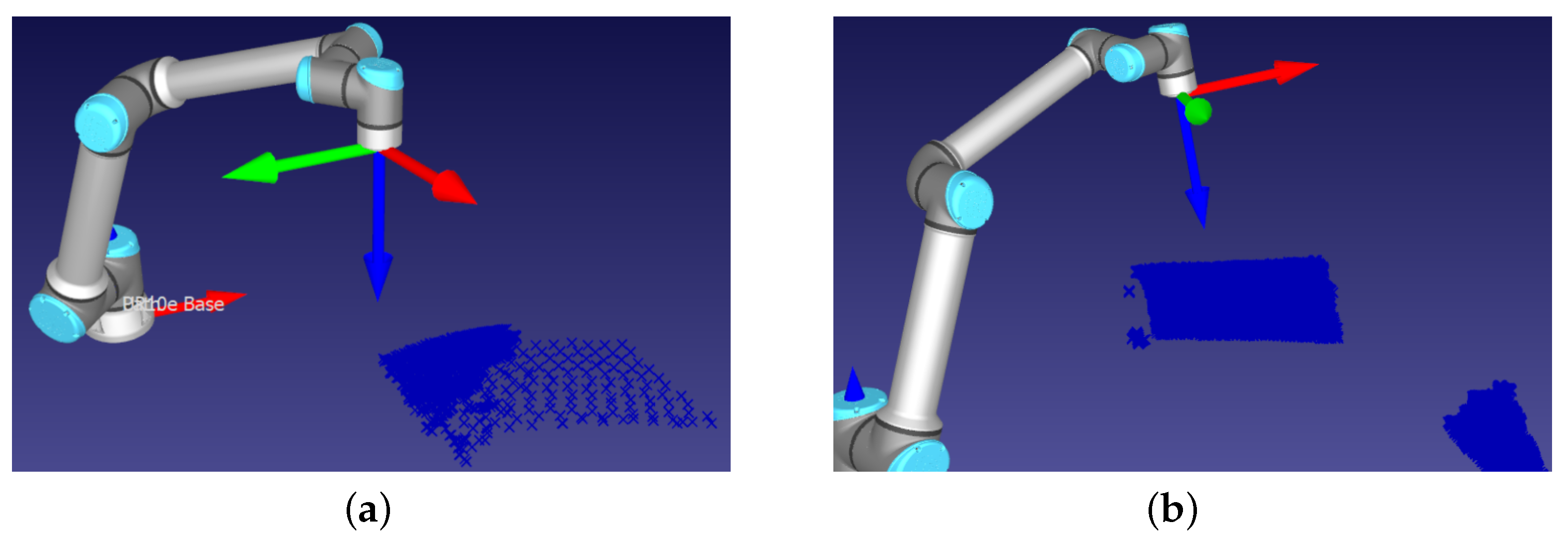
Principle to the path planning process is the initial collision detection procedure to remove points that potentially damage the part or robot. The same wing as used in
Figure 4 was placed at an angle relative to the robot that would cause a collision. The result is a successful removal of points that would potentially cause a collision, as shown in
Figure 5.
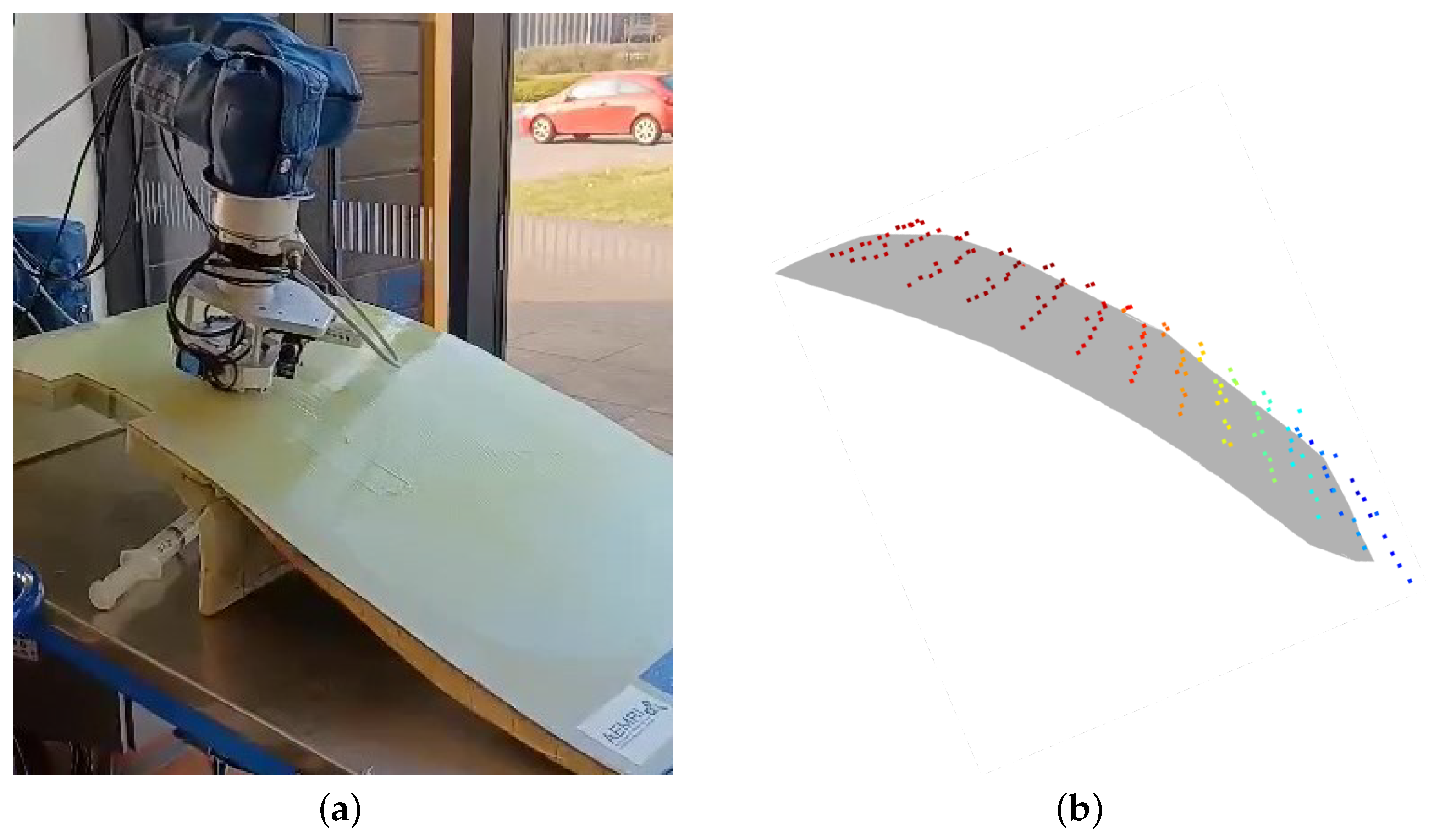
The ability to plan and scan over holed and noisy point cloud data is highlighted in
Figure 6.
Figure 6a shows the initial point cloud corrupted by light-interference. The resultant path executed by the robot is shown in
Figure 6b, shown to cover the part despite the missing and noisy data.
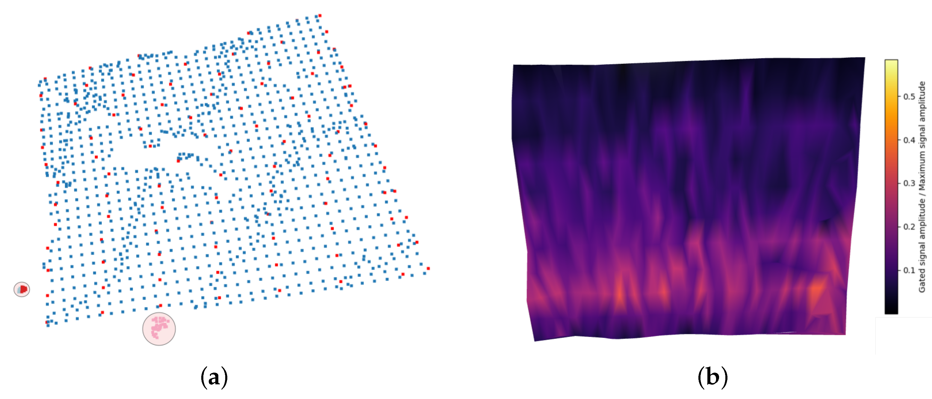
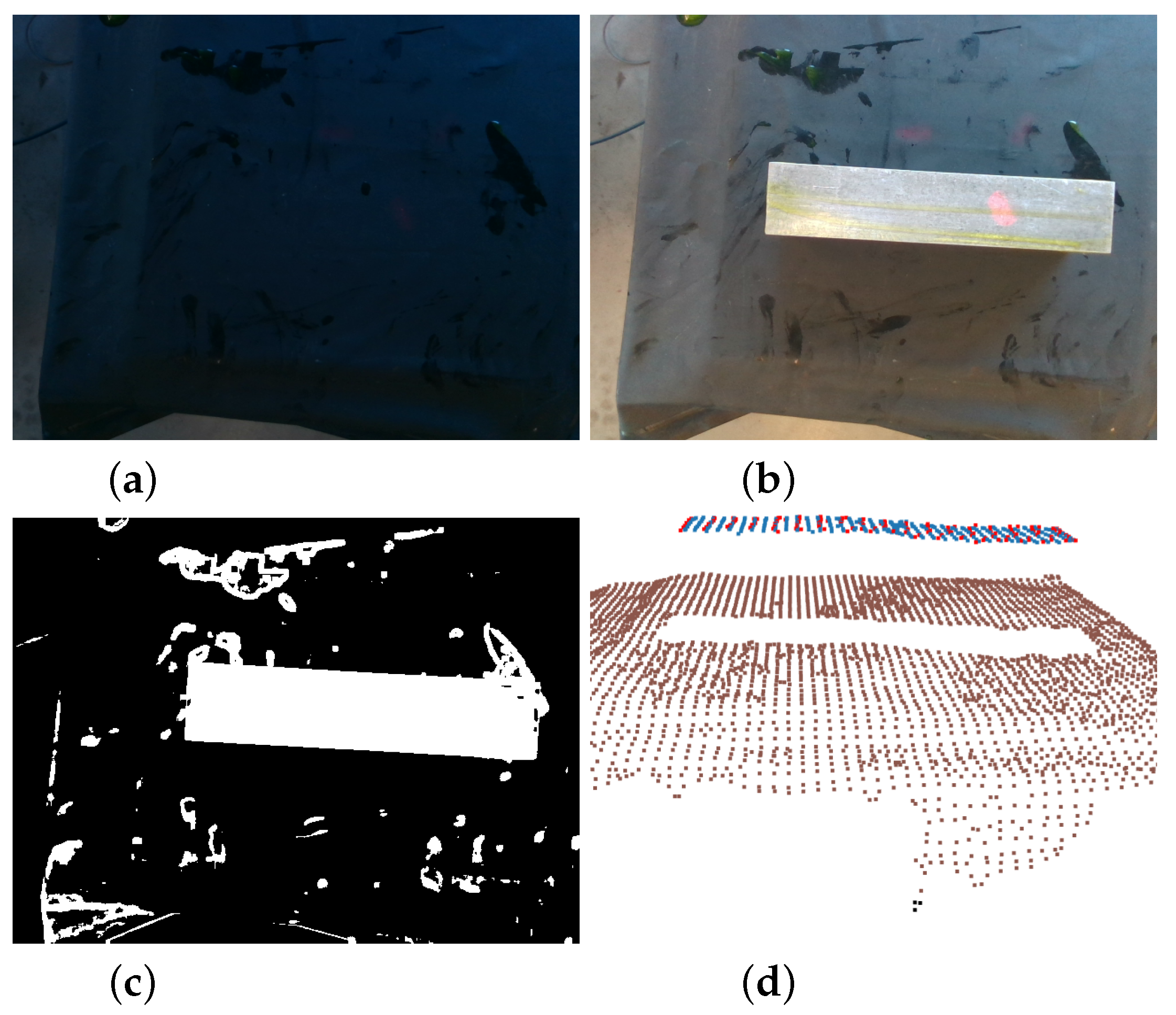
The images shown in
Figure 7 demonstrates the structural similarity method of point-cloud selection prior to clustering and refinement. This is additionally resilient to variable lighting conditions, the main drawback of which is the potential for error when reflective regions are close to the surface of interest, resulting in artefacts seen in
Figure 7c. The point cloud of the artefacts and the surface are then clustered, and the largest or closest to the camera is chosen, resulting in the surface alone being selected in
Figure 7d. The operator should be aware of the placement of small parts so that the surface is not closer to reflective background regions than the clustering radius.
C-scan representations of the data have been validated by imaging the calibration block, seen in
Figure 8. The three side-drilled holes of varying depth are clearly seen on the coloured digital-twin of the surface, highlighted within the image.
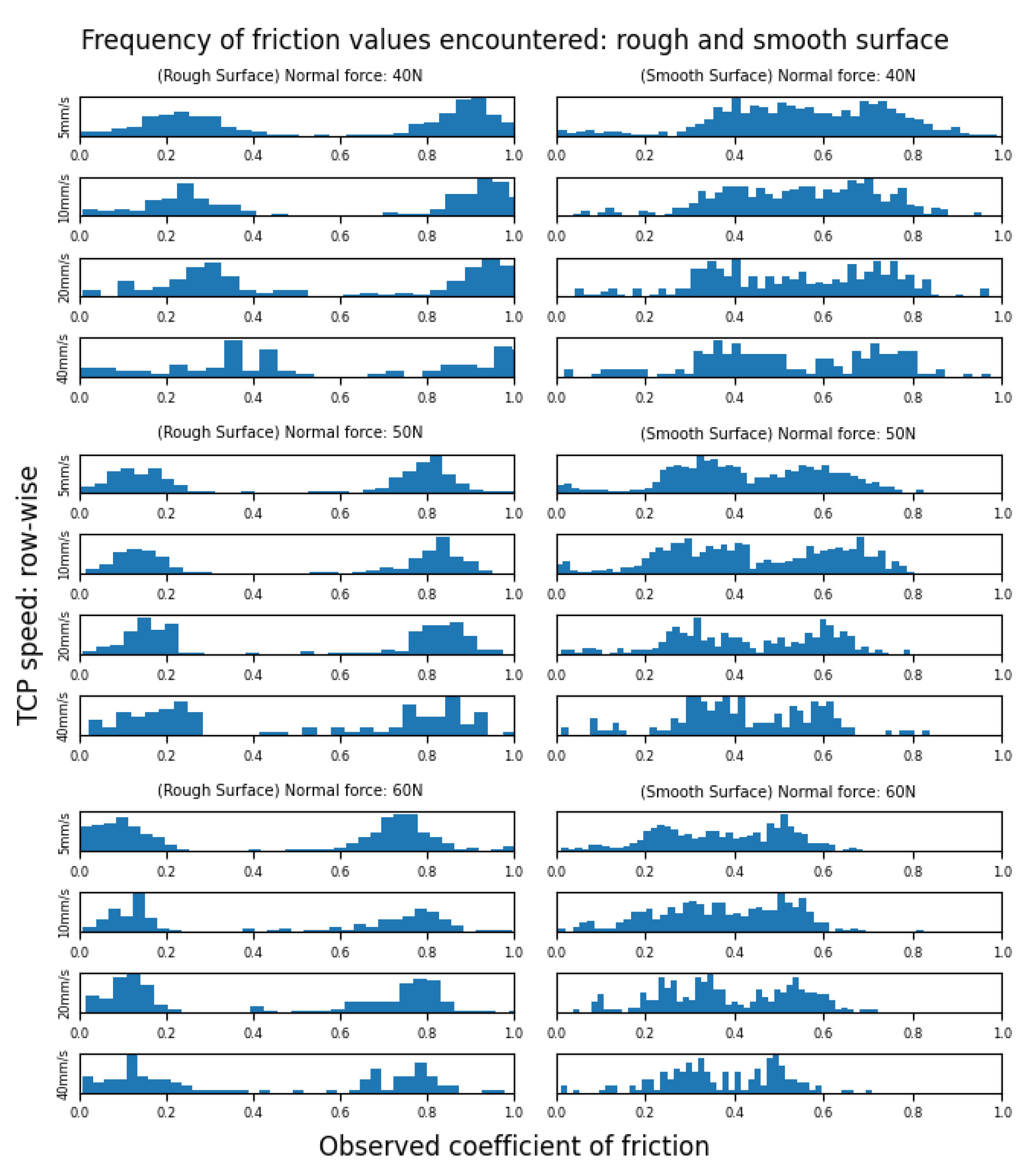
Both a smooth and a rough CFRP sample were used to test friction data at variable pressures and speeds. The results are presented as histogram values in
Figure 9.
While the measured friction across the surface can differentiate between the differing surface roughness values, there is a significant change in the rough surface’s measured friction value. Changes in the hydrodynamic friction of the UT couplant with TCP speed, combined with a mechanical locking of the spring-mechanism explain the shift in friction values across the observed data. The mechanical design of the tool allows for an angled locking of the UT’s sprung support-struts due to the force acting along the strut’s central axis. For rougher surfaces, the frictional force in this direction is great enough to lodge the probe and then on the return, dislodges the tool. The angled face of the tool then also creates a ’bow-wave’ of UT couplant in one direction, allowing the tool to more smoothly pass over the surface with increased lubrication. The result is a split in the frequencies of observed friction values for plates of un-varying roughness, with principle modes becoming visible with greater speed as hydrodynamic friction increases. This is particularly noticeable on the smooth sample, as an increase in speed thereby furthers the split in friction values. Both samples see the peaks of friction inversely correlated with tool load. On the Stribeck curve seen in
Figure 1, the majority of the tool’s aperture is in the well-coupled region, ensuring high quality UT data as there is a thick layer of couplant between the tool and part. This alternating bow-wave effect can also be seen in
Figure 10.
At the raster end-points, the misalignment force is seen as spikes in the friction. The result is that along each raster-line, changes in the friction data can be accurately gathered. However, these data are not transferable across arbitrary raster line-paths. For the purpose of informing operators of changes in surface friction, this is sufficient to highlight potential issues such as significant surface corrosion within the region scanned.
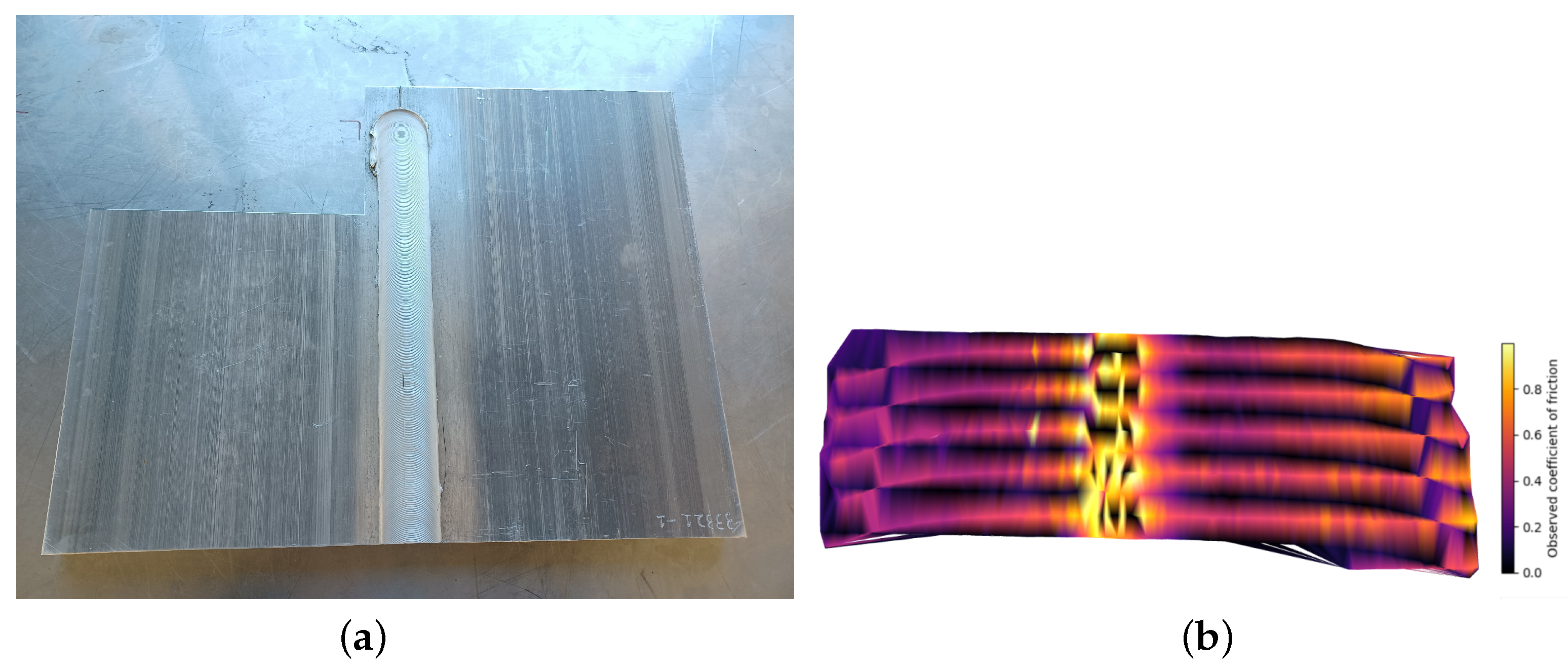
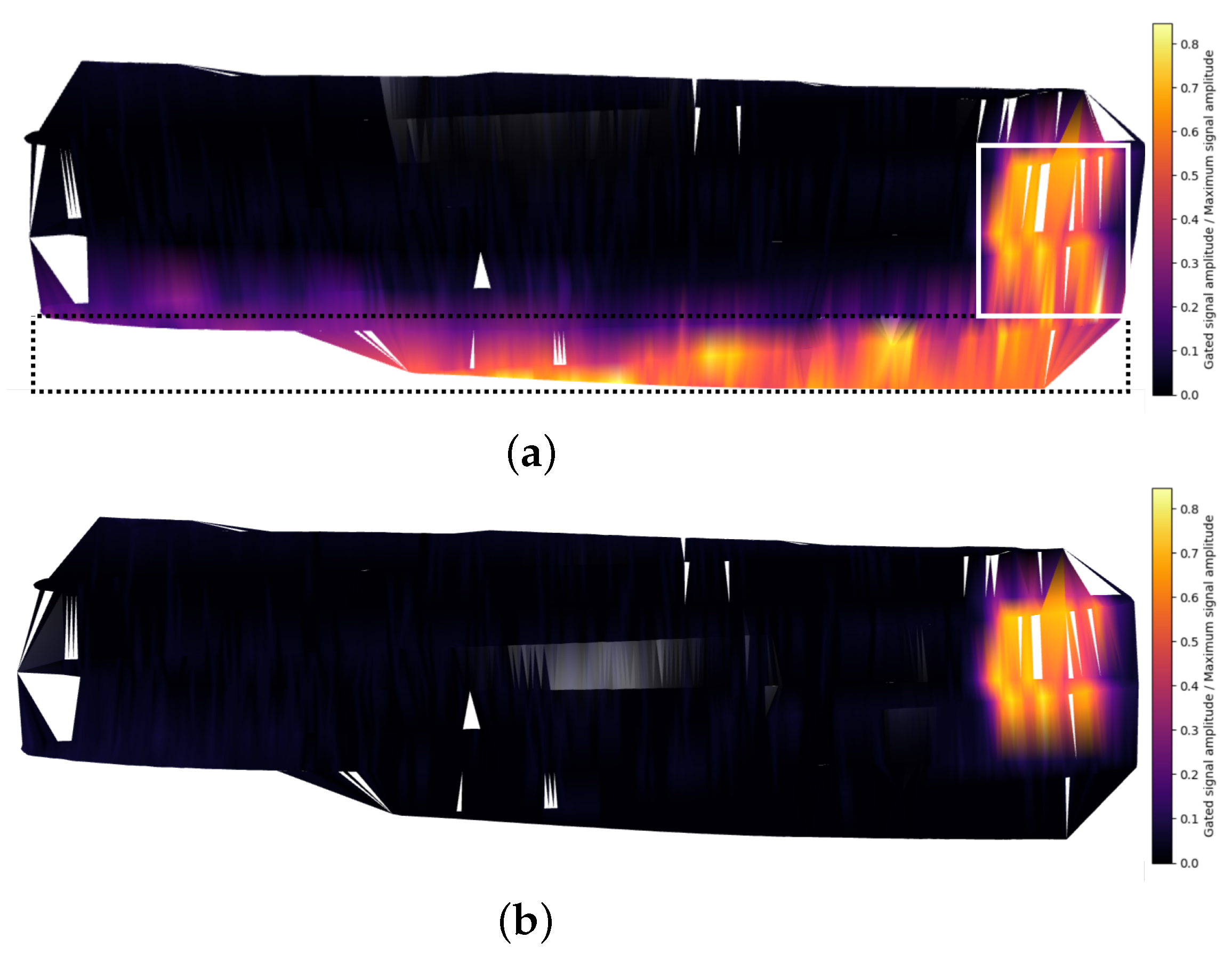
Scanning of a friction-stir-weld is shown in
Figure 10. The ridges of a friction-stir welded plate, shown in
Figure 10a with 0.5 mm ridges at the edge of the weld-line.
In
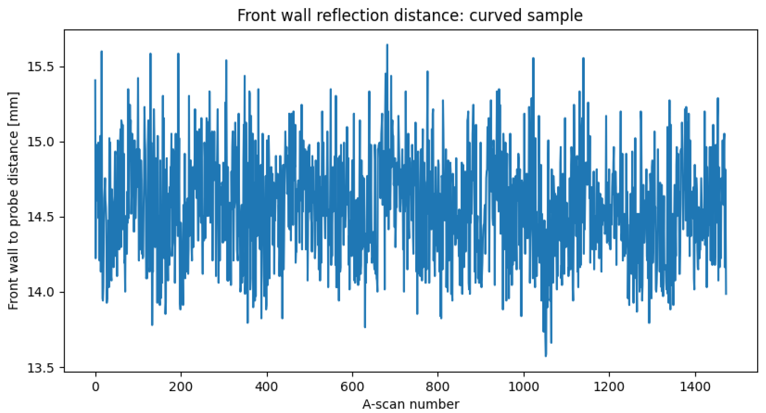
Figure 10b, the ridges can be seen as peaks in the observed coefficient of friction. The normal force control is to maintain consistent contact between the surface and probe, with surface to probe offset values for the curved sample scan presented in
Figure 11.
The standard deviation of 0.36 mm demonstrates the consistency of contact enabled by both the force-control implemented and the sprung tool deployed.
7. Discussion
The two-scale part localisation and path planning methods presented were shown to be robust to different parts with minimal requirements on the placement within the work-cell. However, the criticality of initial tool alignment to guarantee full surface traversal success may require either lasers with greater ranges or operator intervention to re-align the tool in cases of extreme curvature or point-cloud error.
The front-loading of collision avoidance in path planning stages allows the positioning algorithm to react in real-time, correcting position and orientation deviations in a timely way. However, parallelised methods for simultaneous path correction and collision detection may require investigation for robotic platforms that have limited configuration spaces. The UR platform’s joints, unlike many others, have the advantage of a operating range allowing continuous motions over more complex shapes. Taking advantage of these data allows full collision-free coverage of surfaces whose point cloud representations cover all regions of extremal curvature. Future works will investigate integrating this process with the CSFA to capture positions outside of the initial point cloud but still within the robot’s working-range.
While both of the part-localisation stages provided accurate surface positions to use as way-points, for smaller surfaces more appropriate tools such as roller probes or jet-phased array tools may be preferable to prevent wear and tear due to sharp corners.
The novel friction metric has demonstrated it is possible to differentiate regions of high and low friction within each raster-segment, providing useful information to the operator when a surface may be improperly prepared. However, a global friction-coefficient metric is not possible due to mechanical effects.
Finally, the speed-control and correction mechanism has displayed effectiveness in path planning between inaccurate points using local data. The key draw-back is the limitation to convex-shaped regions of parts. For the use-cases considered, the method was sufficient, however for use cases that present large holes in parts, the method may be modified so that the robot retracts within holed regions of a surface.
8. Conclusions
This paper has presented a novel method of autonomous robotised UT deployment that locates the part, plans a path over its surface, approaches the surface without collisions, and scans the surface. In doing so, the proposed methodology frees up operator time and enables flexible collision-free UT sensor deployment to unseen surfaces without the need for a digital twin and without the need for a lengthy pre-scanning and path planning step. The path planning methodology enables greater use of RGB/D cameras applied to robotised NDT, negating their relatively low accuracy without relying on limited-information primitives. Online sensor corrections of the robot’s pose and directions of motion provide a significant bridge from local corrections to global coverage of parts using limited information. The approach further enables future part localisation methodologies that may use Artificial Intelligence approaches to segment work-spaces, potentially resulting in drop-out of surface point cloud positions due to mislabelling.
Local changes in friction can be mapped to an accuracy within that of the CW probe’s planar aperture, informing operators of potential issues with surface preparation and signal gating which is of great interest to the automation of NDT processes.
Mentioned throughout the text are the process’ limitations. Surfaces with inflections between way points may not result in scans that correctly identify way-points. This can be solved by introducing multiple frames within a single path planning step. Small parts undergoing scan procedures in highly reflective work cells may require operator awareness for successful path planning using the Structural Similarity method. Path planning over parts smaller than the work-frame may also result in the probe partially overhanging the surface’s lip. In processing UT data, the operator needs to be aware of any double reflections that may cause UT-signal gating issues. For online corrections the laser-distance measurements may be too widely spaced apart, preventing accurate surface normal alignment. To avoid this issue, the width of their spacing should be minimised. Finally, the success of the path planning method is reliant on the camera calibration quality. The operator is responsible for accurately calibrating the camera tool, so that the produced paths are accurately placed within the robotic work-cell.

