Article

RBF Sliding Mode Control Method for an Upper Limb Rehabilitation Exoskeleton Based on Intent Recognition

School of Mechanical Engineering, Northwestern Polytechnical University, Xi’an 710072, China
*
Author to whom correspondence should be addressed.
Appl. Sci. 2022, 12(10), 4993; https://doi.org/10.3390/app12104993
Submission received: 25 April 2022 / Revised: 12 May 2022 / Accepted: 13 May 2022 / Published: 15 May 2022

Abstract

:
Aiming at the lack of active willingness of patients to participate in the current upper limb exoskeleton rehabilitation training control methods, this study proposed a radial basis function (RBF) sliding mode impedance control method based on surface electromyography (sEMG) to identify the movement intention of upper limb rehabilitation. The proposed control method realizes the process of active and passive rehabilitation training according to the wearer’s movement intention. This study first established a joint angle prediction model based on sEMG for the problem of poor human–machine coupling and used the least-squares support vector machine method (LSSVM) to complete the upper limb joint angle prediction. In addition, in view of the problem of poor compliance in the rehabilitation training process, an adaptive sliding mode controller based on the RBF network approximation system model was proposed. In the process of active training, an impedance model was added based on the position loop control, which could dynamically adjust the motion trajectory according to the interaction force. The experiment results showed that the impedance control method based on the RBF could effectively reduce the interaction force between the human and machine to improve the compliance of the exoskeleton manipulator and achieve the purpose of stabilizing the impedance characteristics of the system.

1. Introduction

In recent decades, the incidence of upper extremity dysfunction caused by stroke has remained high; therefore, rehabilitation training and motor function remodeling of upper extremities has become a key research scope in the field of medical rehabilitation. An upper limb rehabilitation exoskeleton can effectively solve the issues of low efficiency, poor repeatability, and high cost of traditional rehabilitation training [1]. It can obtain accurate training data through various sensors [2], constantly update and formulate scientific and reasonable rehabilitation training methods, and allow for better deployment of follow-up treatment plans for patients to provide patients with more accurate treatment plans and improve the rehabilitation training effect.
A rehabilitation exoskeleton helps patients to perform relevant actions, which requires motion recognition and motion intent detection. During the process, relevant signals can be obtained through needle electrodes, surface electrodes [3,4,5], electroencephalography (EEG), pressure sensors, attitude sensors, pulse wave sensors, etc. Russell provided a definition for motion intent, aimed to systematically review current methods for sensing intent with a comparison of different methods, and proposed the possibility of combining the methods. This provides essential information on addressing task goal interference or predicting future actions [6]. Since sEMG has the characteristics of being advanced, highly correlated, safe, and easy to obtain, it was studied regarding the motion recognition of wrist, shoulder, and elbow joints of upper limbs, and some achievements were obtained. Thelen established a standard muscle balance model based on the Hill model [7]. Based on the analysis of the Hill-type muscle model, muscle-related parameters were used to characterize the relationship between EMG signals and dynamics-related quantities, and the nerve–muscle–skeletal excitation was further established. The system obtains joint moments and related physical quantities through contraction dynamics [8]. Sierotowicz et al. [9] proposed an actuated glove to detect the wearer’s motion intent, which was estimated using a machine learning algorithm based on muscle activity. Liang et al. [10] proposed a knee joint angle prediction model based on sEMG signals, which further combined the Gaussian process model with the nonlinear extrinsic input auto-regressive (NARX) model. A non-parametric probabilistic model was developed based on the physiological properties of muscle activation to achieve an accurate prediction of human motion. Ali et al. [11] proposed an alternative solution for mathematical muscle modeling using regression recurrent neural network (RNN)- and convolutional neural network (CNN)-based sEMG signals and completed an elbow joint angle prediction experiment. Zhang et al. [12] used support vector machine classifiers and genetic algorithms to classify gestures, focusing on the impact of different sEMG feature weights on the classification of similar grasping gestures. The results show that similar gestures have different sensitivities to sEMG features with different weights. Xu et al. [13] completed the related research on the energy kernel characteristics of an sEMG signal and proposed to analyze the energy kernel phase diagram of an sEMG signal based on a convolutional neural network to complete the process of gesture recognition. Tigrini et al. [14] proposed a pattern recognition approach for the shoulder to solve the motion intention detection problem based on sEMG. Linear discriminant analysis (LDA) and multinomial logistic regression (MLR) were used to classify a motion intention model with different feature sets. The experimental results demonstrated that the pattern recognition control is sufficient for solving the motion intention detection problem.
After completing the joint angle prediction based on the sEMG, there are two types of control methods that allow a rehabilitation exoskeleton to improve human–computer interaction performance and realize the flexible movement of the upper limb rehabilitation training [15]. Passive control mainly facilitates the human–machine coupling process using physical structures. Active control means that the sensor at the end of the robot actively detects the information of the interaction between the system and the environment, feeds it back to the control system, and completes the trajectory correction according to the feedback amount to achieve the purpose of compliant control [16]. The proportional–integral–differential (PID) control scheme adopted by the MITMANUS product developed by the Massachusetts Institute of Technology in the United States [17], the dual-mirror rehabilitation training scheme adopted by Stanford University [18], and the passive mode in the arm therapy robot ARMin all have certain effects [19]. Although passive control methods can help subjects follow the predetermined trajectory with high accuracy, they do not guarantee the comfort and safety of the subjects’ upper limb activities [15]. Thus, active compliance control emerges as the times require. The force/position hybrid control method proposed by Raibert [20] et al. decomposes the corresponding interactive forces and positions into their respective orthogonal subspaces and controls each of them to achieve a certain compliance effect. The impedance control and admittance control algorithms proposed by Hogan et al. [21] use the relationship between the force and the position of the robot end to adjust the dynamic impedance characteristics of the system so that the system can express external compliance. Yang et al. [22] proposed a hybrid active control algorithm combined with human motion intention and verified the effectiveness of the control algorithm based on the human upper limb model and the minimum continuous motion estimation model. Li et al. [23] proposed a variable admittance control method based on human intentions, environmental forces, and environmental stiffness to address physical human–robot interaction (pHRI) coupled to environments of unknown stiffness.
To the best knowledge of the authors, the original contributions of this article are summarized in the following points:
(1)
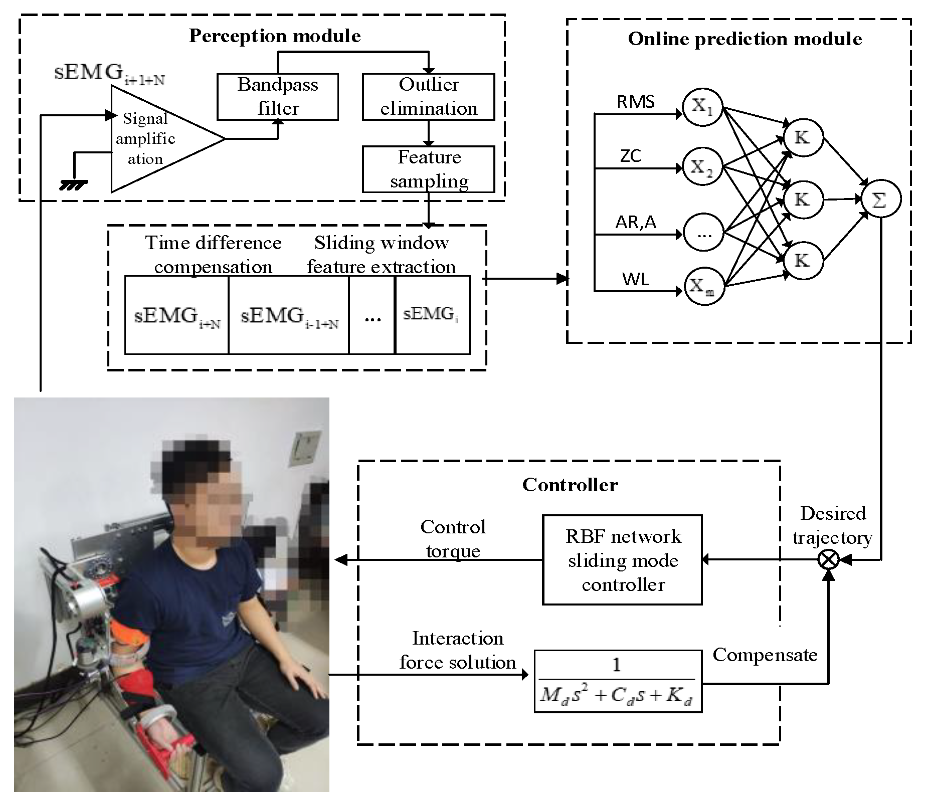
We proposed an sEMG-based LSSVM joint angle prediction model to obtain the patient’s motion intention. According to the physiological characteristics of sEMG, the preprocessing and feature extraction were completed, and the feature optimization of time difference compensation was introduced for the time delay problem that exists in real-time processing.
(2)
An adaptive sliding mode controller based on an RBF network approximation was proposed for exoskeleton control, which improved the fast approximation ability of the model and the compensation for uncertainty disturbance. The error of the trajectory tracking was dynamically adjusted by acquiring the human–computer interaction force to ensure the flexibility of the rehabilitation process.
The remainder of the paper is organized as follows: Section 2 briefly introduces the joint angle prediction method based on sEMG. In Section 3, the controller design based on an RBF network was proposed. Section 4 presents the experimental settings and results. The conclusion and future work are presented in Section 5

2. Estimation of Joint Motion Intention Based on sEMG

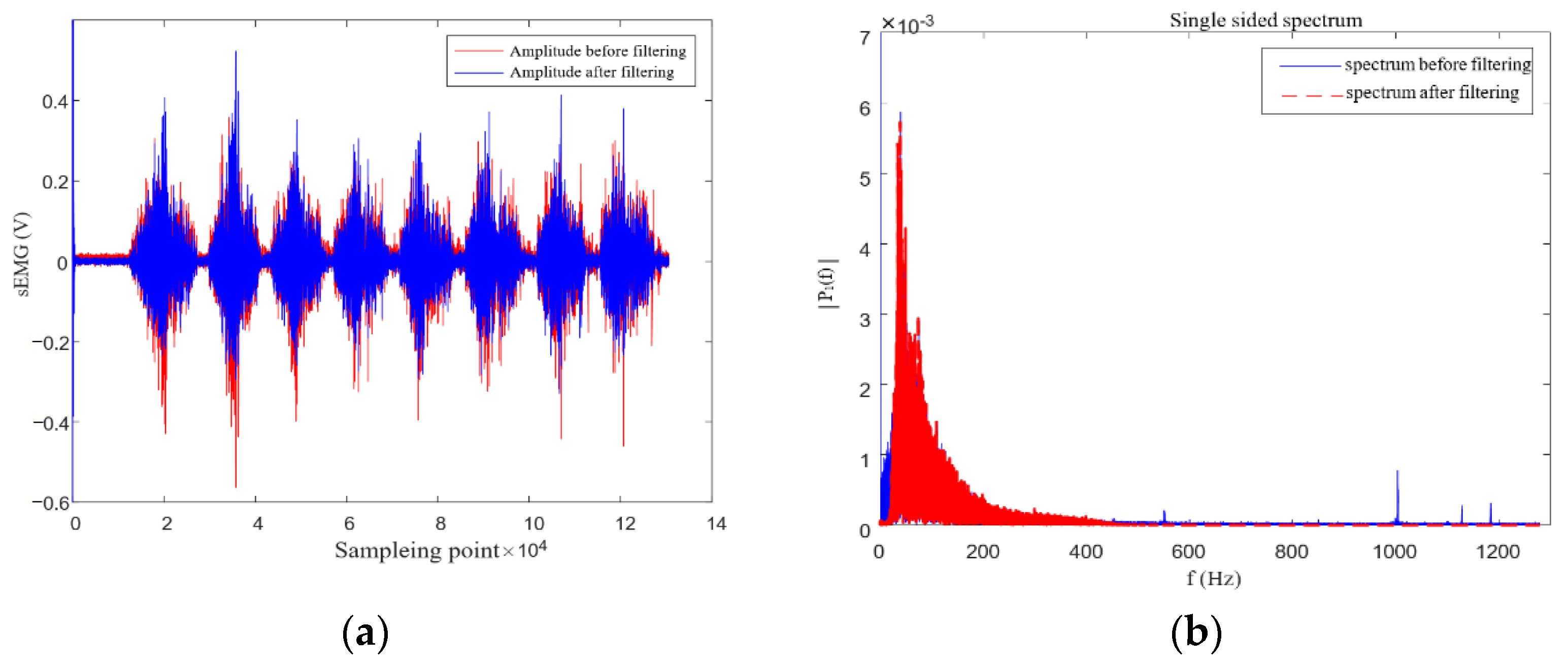
2.1. sEMG Signal Pre-Processing

Aiming at issues such as the noise interference of the original sEMG signal and the sampling rate not being aligned, signal preprocessing was conducted in this study. First, since the sEMG signal was very weak, it needed to be amplified 1000 times after acquisition. In addition, in order to filter out noise signals outside the effective energy band, filtering was required. According to the characteristics of the sEMG signal, the IIR-type Butterworth filter was selected in this study to remove the information outside the frequency band of the sEMG effective energy, and then the ideal frequency domain response curve could be obtained. The filter gain G   ( ω ) is
G 2 ( ω ) = | H ( j ω ) | 2 = G 0 2 1 + ( ω ω c ) 2 n
where n is the order of the filter, G 0 is the DC gain coefficient, and ω c is the cut-off frequency.
Relevant parameters are set to complete the filter design. The time-domain waveform and unilateral spectrum of the sEMG signal after filtering are shown in Figure 1. Since the filtering was mainly for frequency interception, the amplitude before and after filtering was basically unchanged, the filtered signal had fewer burrs, the high- and low-frequency signals were basically filtered out, and the signal energy was concentrated within 500 Hz. It can be observed that there was still 50 Hz power frequency interference in the sEMG signal. There are many ways to solve such problems, but relevant information will be lost after removal. Therefore, this study did not manage the power frequency interference.
Since the order of magnitude of each eigenvalue was different, in order to ensure the consistent input distribution and speed up the model calculation and convergence speed, the maximum and minimum method was used to complete the normalization process and the eigenvalue x i was normalized between the values [−1, 1] using
x i = 1 + 2 ( x i x min ) x max x min
where x i is the normalized value and x max and x min are the maximum and minimum values of the eigenvalues of the normalization process, respectively.
The processed signal had redundant information and could not be directly used to identify human motion intentions. In order to further improve the prediction speed, accuracy, robustness, and generalization of the model, it was necessary to convert the original EMG signal into a set of eigenvalues that could clearly represent the physical quantities of joint motion. According to the literature [24], the eigenvalues that have a greater influence on the prediction and the eigenvalues that are not sensitive to electrode offset are selected, and then the feature space is constructed to improve the robustness of the system. The root-mean-square (RMS) signal wavelength (WL), zero crossing (ZC), and attitude acceleration eigenvalues were selected as the eigenvalues of this study, and the mixed vector was formed with attitude angle.
(1)
The RMS reflects the validity of the signal, which is expressed as
R M S = 1 N i = 1 N x 2 ( i )
where x(i) is the sEMG amplitude sampling sequence and N is the number of sampling points in the moving sliding window; in this study, N was 256.
(2)
The WL reflects the degree of cumulative change of the sEMG during a period, which is expressed as
W L = i = 1 N 1 | x ( i + 1 ) x ( i ) |
(3)
The ZC points are the number of crossings between the amplitude of the sEMG signal and a certain coordinate threshold, which represent an approximate estimation of the frequency domain characteristics as
Z C = i = 1 N 1 | sgn ( x i x i + 1 ) | | x i x i + 1 | threshold sgn ( x ) = { 1 ,   i f   x threshold 0 ,   i f   x threshold
The data set was established based on the above description as
X = [ x 1 , x 2 , , x n ]
where x i is [ x WLi , x RMSi , x ZCi , x ai ] and represents the combined sequence of all eigenvalues in the ith group; n is the number of labels.
Y = [ y 1 , y 2 , , y n ]
where y i is the angle of the joint action corresponding to the discrete sampling points; then, the training sample set (x, yi) (i = 1, 2, …, n) is constructed.
In this study, the correlation coefficient (CC) and the root-mean-square difference (RMSE) were selected as the evaluation effects of the regression prediction of the human elbow joint angle, where CC is
C C = C o v ( θ e , θ a ) D ( θ e ) D ( θ a )
where θ e is the predicted angle, θ a is the actual angle, Cov is the covariance, and D is the variance. The performance of the estimation is better as the result approaches 1. Meanwhile, the coefficient RMSE works the opposite way, where the RMSE is
R M S E = i = 1 N ( θ e θ a ) 2 N
where N is the number of predicted numbers.

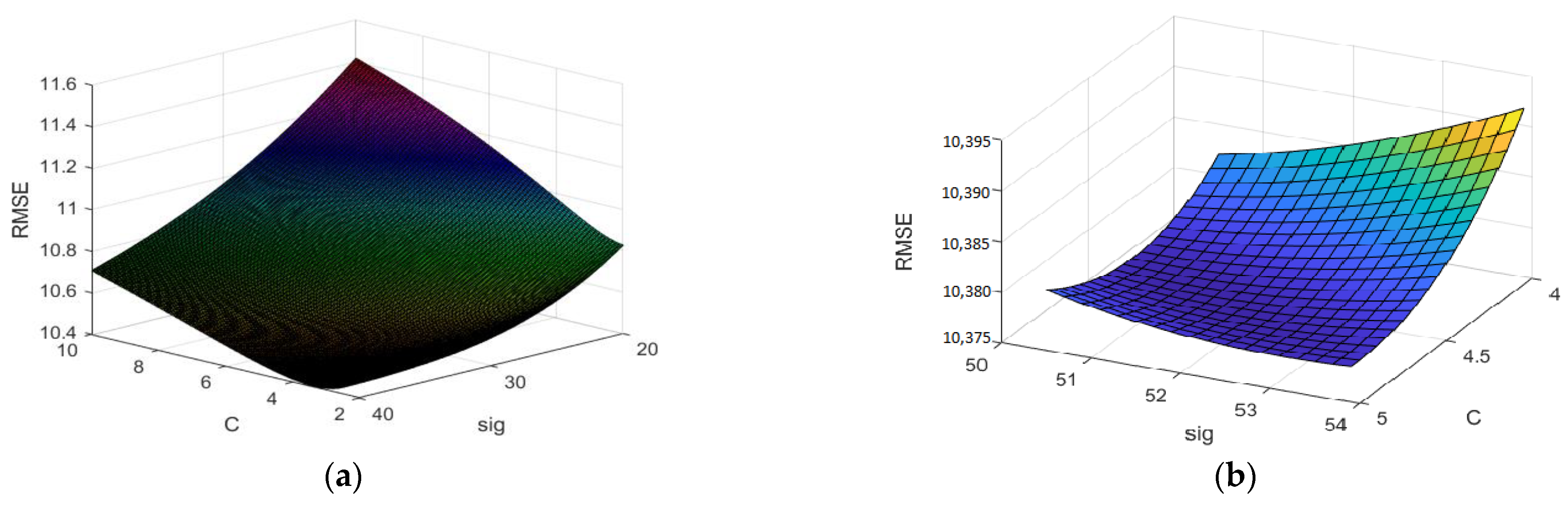
2.2. Joint Angle Prediction Based on LSSVM

This study proposed using machine learning to build a mapping model to complete the continuous motion regression estimation. The least-squares support vector machine (LSSVM) replaces the traditional support vector machine and maps the original data to a high-dimensional feature space to achieve linear regression [25,26]. The data set is transformed from the current space to the high-dimensional feature space through the nonlinear function φ ( x ) , that is
φ ( x i ) = ( ϕ ( x 1 ) , ϕ ( x 2 ) , , ϕ ( x n ) )
where φ ( × i ) is the ith group of eigenvalues of the input joint angle prediction model and ϕ ( × 1 ) , ϕ ( × 2 ) ,⋯ ϕ ( × n ) are the n elements that constitute the input.
The loss function of the optimal problem (calculation formula for structural risk) is
min J ( U , e ) = min ( 1 2 U T U + C i = 1 n e i 2 )
where U is the support vector machine weight space; e i is the allowable error between the predicted value and the actual value; and C is the penalty term coefficient (normalization parameter), which is used to adjust the model structure.
The loss function of the optimization problem used to construct the regression model of the least square method is
y i = U T φ ( x i ) + b + e i i = 1 , 2 , , n
where y i is the output label corresponding to the ith group of eigenvalues and b is the intercept term coefficient.
The Lagrange multiplier method was used to transform (11) and (12) into
L ( U , b , e i , α ) = J ( U , e ) i = 1 n α i ( U T φ ( x i ) + b y i )
where α = [ α 1 , α 2 , α n ] is Lagrange multiplier coefficient.
Taking the partial derivatives of U ,   φ ,   e i ,   a n d   b based on Karush–Kuhn–Tucker (KKT) rules gave
{ δ L δ U = 0 δ L δ b = 0 δ L δ α = 0 δ L δ e i = 0 { U = i = 1 n α i φ ( x ) i = 1 n α i = 0 y i = U T φ ( x i ) + b + e i α i = C e i
The model parameters could be obtained by converting the above formula into a linear equation system:
[ 0 1 1 1 1 1 K ( x 1 , x 1 ) + 1 2 C K ( x 1 , x 2 ) K ( x 1 , x n ) 1 K ( x 2 , x 1 ) K ( x 2 , x 1 ) + 1 2 C K ( x 2 , x n ) 1 K ( x n , x 1 ) K ( x n , x 2 ) K ( x n , x n ) + 1 2 C ] [ b α 1 α 2 α n ] = [ 0 y 1 y 2 y n ]
Equation (15) could be simplified to
δ N = [ 0 H T H Ω + C 1 I ] Y N
where δ N = [ b , α 1 , .. , α N ] T are the model parameters, H = [ 1 , 1 , , 1 ] T , and Y N = [ 0 , y 1 , y 2 , , y n ] T .
The kernel function of the LSSVM algorithm satisfies the Mercer condition, which is
Ω i , j = φ ( x i ) φ ( x j ) = K ( x i , x j ) i , j = 1 , 2 , , N
where K is the kernel function, which represents the inner product between each element in the high-dimensional feature space.
The Gaussian kernel function selected in this study was
K ( x , x i ) = exp ( x x i 2 2 σ 2 )
Thus, the estimated angle y for the new output vector x was
y ^ = i = 1 N α i K ( x , x i ) + b

3. Controller Design Based on RBF

In this study, a sliding mode controller based on variable structure control was designed for passive rehabilitation motion control of the upper limb exoskeleton. Expressing the general form dynamics model of the upper limb exoskeleton as a state-space equation, we have
{ Δ M = M M 0 Δ C = C C 0 Δ K = K K 0 Δ τ d = τ d τ d 0
where M 0 is the nominal value of the inertia matrix, ∆K is the estimated error of the inertia matrix, C 0 is the nominal value of the Coriolis force matrix, ∆C is the estimated error of the Coriolis force and the centripetal force matrix, K 0 is the estimated value of the gravity term, ∆K is the estimated error of the gravity term, τ d 0 is the nominal value of the external disturbance, and Δ τ d is the estimated error of the disturbance.
The sliding surface function is defined as
R = e ˙ + P e
where P = P T = [ p 1   p 2     p n ] T > 0 , and e 0 while R 0 .
From (21), we obtained
q ˙ = R + q ˙ d + P e
Combining (22) with the exoskeleton Lagrangian dynamic model, we obtained
M R ˙ = M ( q ¨ d q ¨ + P e ˙ ) = M ( q ¨ d + P e ˙ ) M q ¨ = M ( q ¨ d + P e ˙ ) + C q ˙ + G + F + τ d τ = M ( q ¨ d + P e ˙ ) C R + C ( q ˙ d + P e ) + G + F + τ d τ = C R τ + f + τ d
It can be seen that this model contained all the estimated model information of the upper limb exoskeleton, including gravity, friction, and interference, as we considered the motor as a connecting rod, Therefore, the whole system could be approximated by the RBF network, and then a sliding mode robust controller that did not require model information was designed.
The Gaussian kernel function was designed as
φ j = exp x c j σ j 2 ,   j = 1 , 2 , , m
f ( x ) = W T φ + ε
where x = [ e   e ˙   q d   q ˙ d   q ¨ d ] is the input of the RBF network, W is the desired ideal weight of the network, φ j is the intermediate function, and ε is a very small positive real number.
Then, we obtained
f ^ ( x ) = W ^ T h
where f ^ ( x ) is the approximation term to f ( x ) , W ˜ = W W ^ , and | | W | | F W max .
Combining (25) and (26), we obtained
f f ^ = W T φ + ε W ^ T h = W ˜ T h + ε
The control law was designed as
τ = f ^ + K s R υ
where K s is the sliding mode surface function coefficient and υ = ( ε n + a d ) sgn ( R ) is the robust term, which is used to overcome the unstable error.
In order to update and adjust the RBF network weight parameters, we set the RBF network weight adaptive law as
W ^ ˙ = L φ R T   ( L = L T > 0 )
Substituting (28) into (23), we obtained
M R ˙ = C R [ f ^ + K s R υ ] + f + τ d = ( K s + C ) R + W ˜ T φ + ( ε + τ d ) + υ = ( K s + C ) R + η 1
where η 1 = W ˜ T φ + ( ε + τ d ) + υ .
The Lyapunov function was constructed as
V = 1 2 R T M R + 1 2 t r ( W ˜ T L 1 W ˜ )
Taking the derivative of both sides of (31), we obtained
V ˙ = R T M R + 1 2 R T M ˙ R + t r ( W ˜ T L 1 W ˜ ˙ )
Substituting (30) into (32), we obtained
V ˙ = R T K s R + 1 2 R T ( M ˙ 2 C ) R + t r W ˜ T ( L 1 W ˜ ˙ + φ R T ) + R T ( ε + τ d + υ )
The manipulators had the following mathematical properties according to [27]:
(1)
The oblique symmetry of the dynamic model of the robotic arm system: R T ( M ˙ 2 C ) R = 0 ;
(2)
R T W ˜ T φ = tr   ( W ˜ T φ R T ) ;
(3)
W ˜ ˙ = W ^ ˙ = L φ R T .
Thus, we obtained
V ˙ = R T K s R + R T ( ε + τ d + υ )
Since
R T ( ε + τ d + υ ) = R T ( ε + τ d ) + R T [ ( ε n + a d ) sgn ( R ) ] = R T ( ε + τ d ) R ( ε n + a d ) 0
we obtained
V ˙ R T K s R 0
Since V > 0 and V ˙ 0 , R and W are bounded. Therefore, since R = 0 when V ˙ = 0 , it can be judged that the closed-loop system is asymptotically stable; therefore, when t ,   R 0 , then e 0 ,   e ˙ 0 .
In the active rehabilitation stage, we added an impedance feedback model on the basis of the RBF network approximated controller to realize the compliant control process instead of only considering the position error as gradually converging to 0. The impedance relationship of the system was
F e = M Δ θ ¨ + B Δ θ ˙ + K Δ θ
where Δ θ , Δ θ ˙ , and Δ θ ¨ are the differences between the expected value and the actual value of angle, angular velocity, and angular acceleration, respectively; F e is the local contact force between the exoskeleton robot and the limb; M is the system inertia parameter matrix; B is the system damping parameter matrix; and K is the system stiffness matrix.
By performing an inverse Laplace transform on (37), we obtained
Δ θ = θ d θ = 1 M S 2 + B S + K
The aforementioned control model was used as the inner loop, the outer loop adopted the impedance control model, and the LSSVM model was used as a feed-forward input to obtain the desired trajectory point generated by the patient, calculate the required control input torque through the sliding mode adaptive law, and input it to the virtual prototype model to allow for settlement of human–computer interaction torque.

4. Main Results

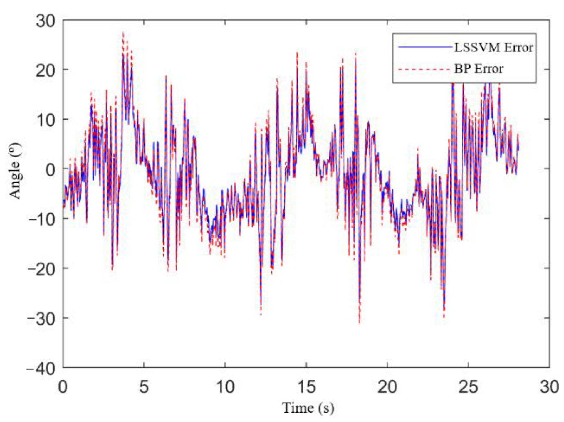
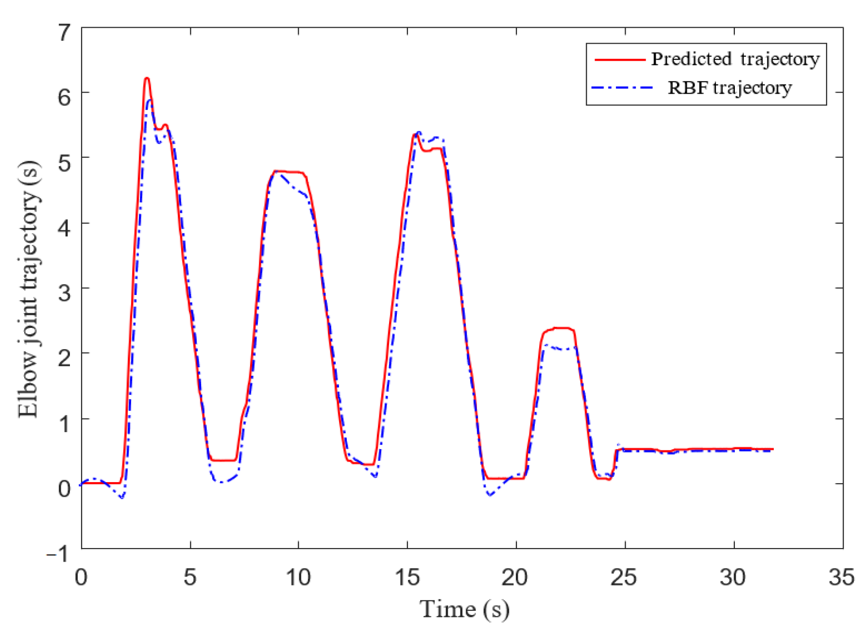
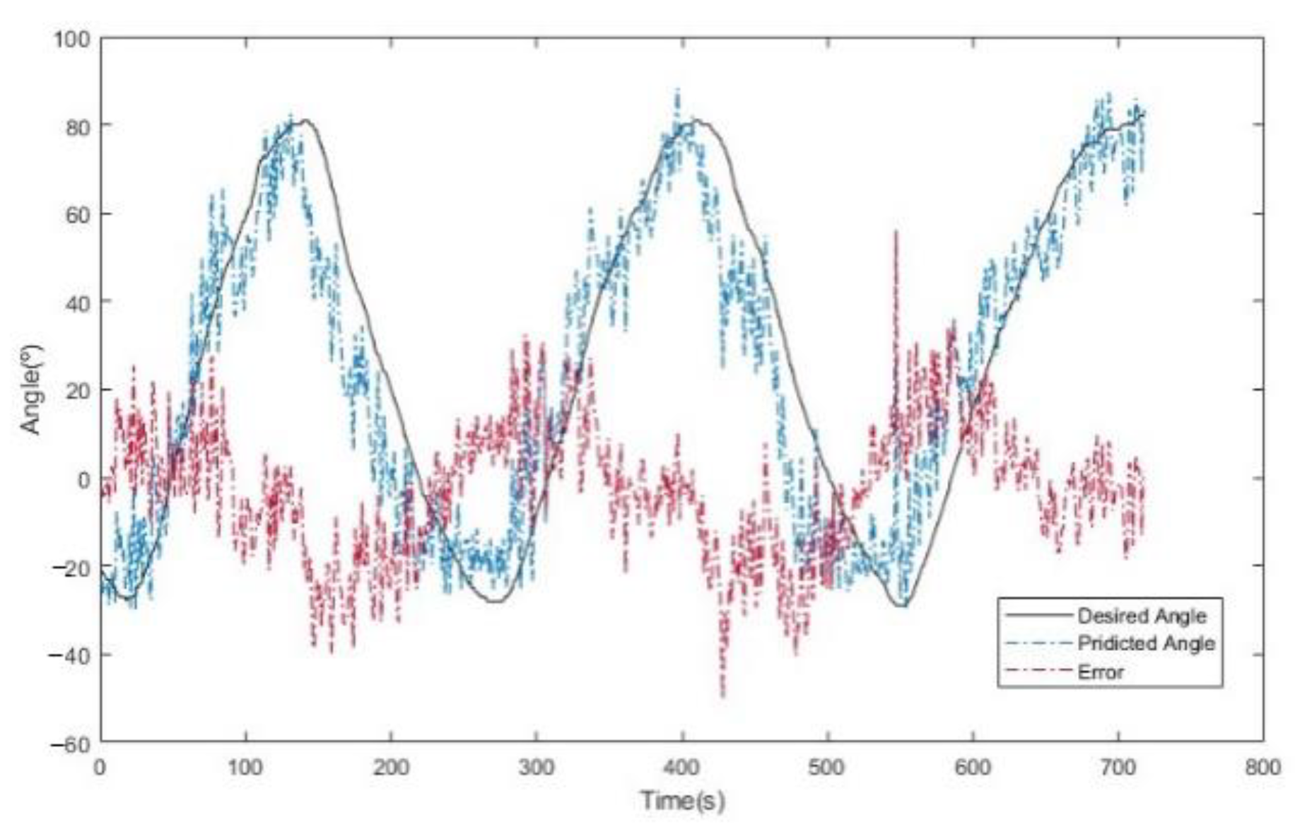
4.1. Joint Angle Prediction Experiment Based on LSSVM

In this study, the elbow joint rehabilitation training was studied, and the positions of the sEMG and the pose sensor in the experiment are shown in Figure 2. In order to prevent the electrode from shifting during the movement, the sensor was fixed with medical tape and a wrist guard.
First, the range of parameters C and σ were determined in the three-dimensional space, as shown in Figure 3a. After that, the method of subsection local optimization was adopted. Since the selection of hyperparameters did not have a great impact on the range of RMSE values, a smaller step size was not necessary, as shown in Figure 3b. According to the grid color, the influence of the two different ranges on RMSE was determined as shown in the figure, and the hyperparameter of the experimental object was finally determined as (C, σ) = (4.53, 51.56). The time difference compensation processing was performed on the LSSVM, and the result is shown in Figure 4. It was obvious that the error between the desired value and the estimated value was acceptable.
The backpropagation neural network (BPNN) was chosen to compare with the LSSVM algorithm. The number of nodes in the hidden layer of the BPNN was set to 5, the number of iterations was set to 1000, the network learning rate and the final target error were set to 0.01 and 0.00001, and the interval between the hidden layer and the output layer was selected. The transfer functions were the sigmoid function and the linear transfer function. In order to visually compare the prediction performance of the two methods, the error is shown in Figure 5. It can be seen intuitively from the figure that the output error of the LSSVM prediction algorithm was smaller compared with the manual adjustment of the optimal parameters; therefore the LSSVM algorithm was better than the BPNN at predicting the joint angle error of patients.

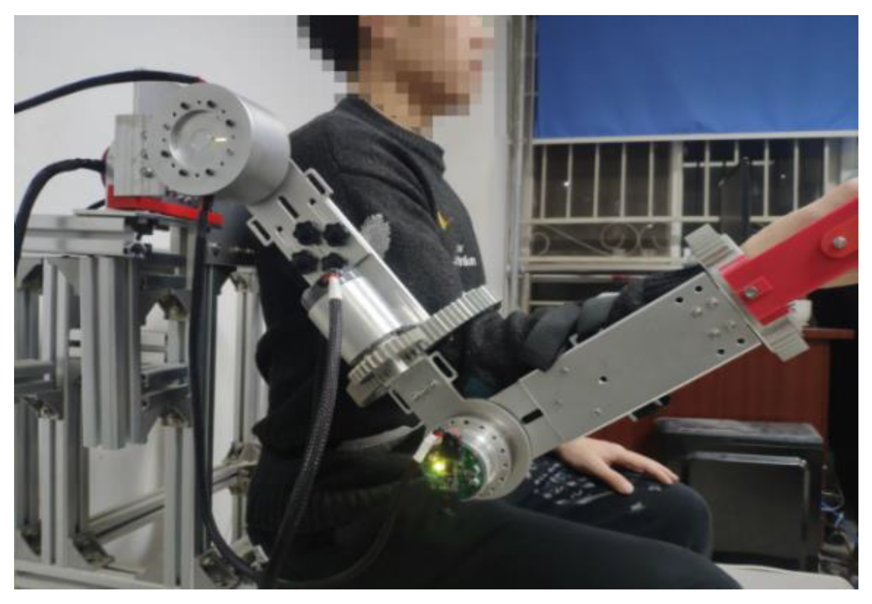
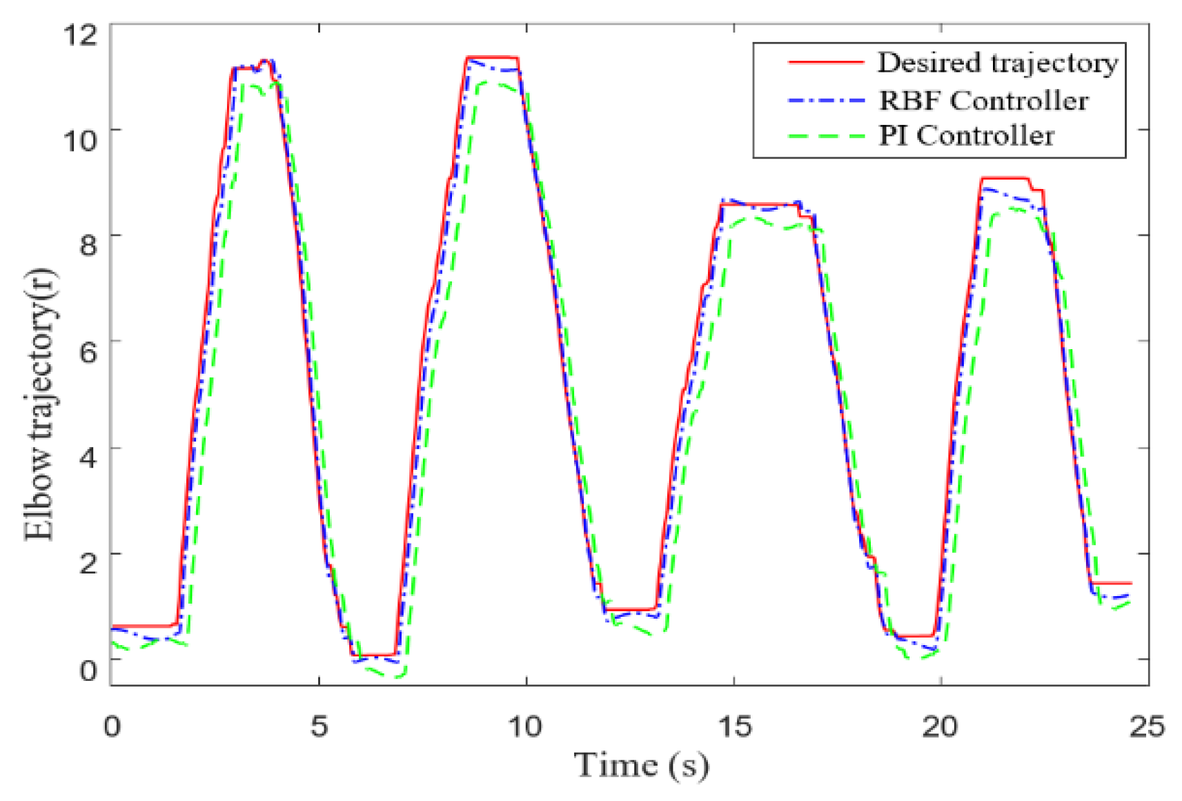
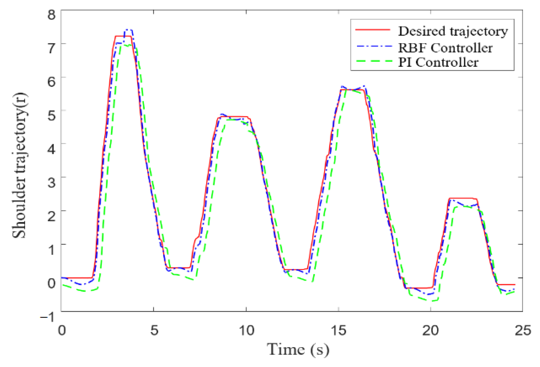
4.2. Passive Rehabilitation Training Experiment

In order to realize the teaching reproduction of passive training, the joint actuator trajectory points needed to be captured first. The experimental process is shown in Figure 6. The simulated patient used the upper limb to drive the exoskeleton robotic arm. The encoder recorded the current trajectory position point and used passive training to control the desired trajectory point. The obtained shoulder joint trajectory and elbow joint trajectory are shown in Figure 7 and Figure 8, respectively. The results showed that the actual trajectory was basically consistent with the expected trajectory, and the local jitters indicated the instability of the control input torque caused by the change of current noise, which led to the position deviation of the actuator. Due to the large moment of inertia of the motor, the speed could not be converted in time at the highest position point, and the newly issued position command changed to a certain tracking error. It can be clearly seen that this kind of position change was unavoidable.
The red lines in Figure 7 and Figure 8 represent the joint trajectory points recorded in the current mode, the blue dot-dash line represents the RBF sliding mode impedance control method, and the green line represents the set proportional–integral (PI) position loop mode. From the comparison of the errors, it was found that the tracking effect of the RBF sliding mode control was better than that of the PI mode. At the same time, observing the two figures, it can be seen that the different control algorithms had a certain deviation compared with the expected trajectory. There was a certain time delay caused by the system approximation when applied to the hardware. The sliding mode control delay effect of the RBF network approximation was significantly better than that of the PI mode.

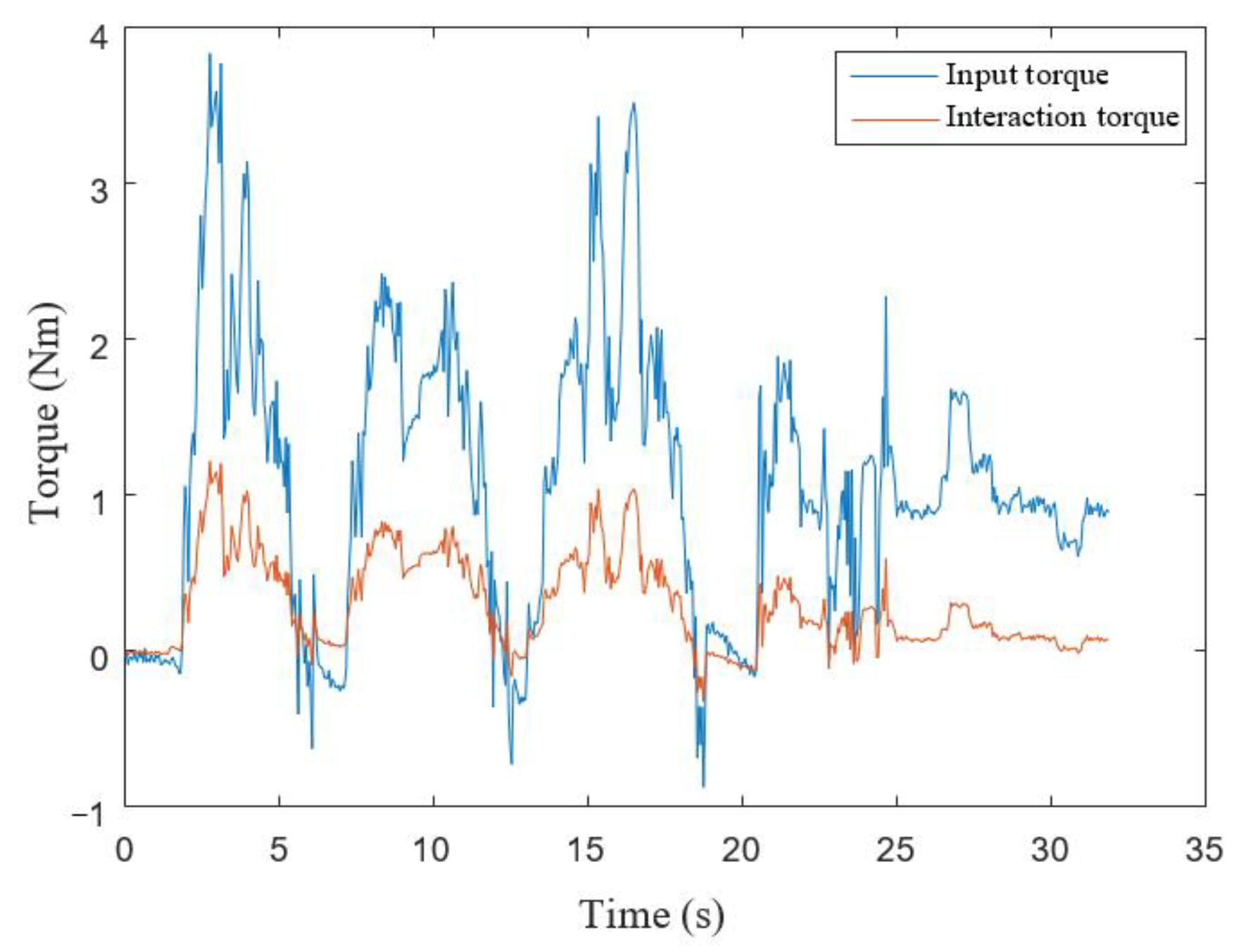
4.3. Active Rehabilitation Training Experiment

As mentioned above, the rehabilitation experimental movements designed in this study were aimed at the degree of freedom (DoF) of flexion/extension of the elbow joint, that is, only the actuator at the elbow joint was used. The control block diagram of active rehabilitation training is shown in Figure 9. The perception module was used to obtain the relevant posture information and sEMG information required for motion recognition, and the feature values in the sliding window were preprocessed and extracted, and then input into the offline trained LSSVM model. The conversion of the control amount was input into the joint actuator, and the RBF sliding mode controller realized the position inner loop control while the impedance outer loop controller maintained the impedance relationship between the patient and the manipulator and realized the compliance control process based on the desired trajectory. The entire closed-loop rehabilitation training process completed the perception, decision-making and control steps in one control cycle, realizing active rehabilitation training for patients.
Due to the noise and sudden change in the position, the prediction results of the sEMG could not be applied directly to the actuator. Therefore, a fourth-order Butterworth filter was used to process the prediction results, where the low-pass cut-off frequency was set to f c = 10   Hz , and the stepping position of the actuator was set to be no greater than 0.5R to avoid the generation of human–robot interaction forces due to large prediction values.
The processed trajectory curve was relatively smooth, as shown in Figure 10. It can be observed that muscle instability of patients led to changes in the sEMG signals at the highest point, and further led to a decrease in the predicted trajectory within the range of the maximum prediction error e max , which was approximately equal to the mean absolute error (MAE). There was a certain control time delay in the active control process of the predicted expected trajectory points, but the overall tracking performance was good.
The elbow joint torque and the human–robot interaction torque were obtained, as shown in Figure 11. Since the initial position was not completely vertical in the sagittal plane, the initial torque was not 0, and the whole process could basically reflect the movement changes. The human–robot interaction torque was maintained at about 0.2 Nm and there were slight fluctuations, which were due to the actual human–robot interaction process. In summary, the sliding mode adaptive impedance algorithm based on the sEMG recognition could accurately obtain the patient’s motion intention and assist the patient in rehabilitation training, which has certain application value in the field of rehabilitation training.

5. Conclusions

This study mainly analyzed the problems of insufficient human–computer interaction in upper limb exoskeleton rehabilitation training and proposed a rehabilitation training control method based on sEMG active motion intention recognition. A joint angle prediction model based on LSSVM was established to obtain the patient’s motion intention. In addition, in view of the complex calculations of the nonlinear system dynamics model of the strongly coupled upper limb exoskeleton and the disturbance of environmental uncertainty, an adaptive sliding mode passive control and sliding mode variable impedance active control algorithm based on RBF network approximation were proposed. The experimental test results showed that the passive control method reduced the torque chattering problem in the process of trajectory tracking and reduced the trajectory error. This method could effectively approximate the nonlinear system dynamics model of the exoskeleton manipulator and reduce the calculations in the system. The complexity improved the computing efficiency and the robustness of the control system, sped up the dynamic response time of the system, and improved the strong coupling of the system. The active control method integrated the patient’s movement intention and reduced the human–computer interaction force in the training process, which realized the flexible movement of the upper limb rehabilitation exoskeleton. Aiming at the perception decision making and control of the upper limb exoskeleton manipulator under rehabilitation training, this study completed the overall design of the upper limb exoskeleton rehabilitation training system and the research on the control method of active and passive compliance rehabilitation training, which provides a new method for the control research of rehabilitation robots.
Although the feasibility and stability of the proposed method were clarified, there were still some limitations to our work that we need to state. First, this research aimed to assist hemiplegia patients to realize rehabilitation training with upper limb exoskeleton. However, due to the COVID-19 and research conditions, we could not conduct experiments with the participation of real patients to verify the angle prediction accuracy of a diseased upper limb. Second, the trajectory tracking based on an sEMG reconstructed angle scheme is vulnerable to system uncertainties and disturbances, which often leads to performance degradation. In future work, event-triggered sliding mode control (ETSMC) will be applied to our work since ETSMC can reduce the high-frequency chattering using the symbolic function. In this way, resources can be used reasonably and effectively, and the working time of the controller can be extended.

Author Contributions

The contributions of all authors are listed as follows: conceptualization, D.K., W.W. and D.G.; methodology, D.K. and D.G.; software, D.K.; validation, D.K. and D.G.; formal analysis, D.K.; investigation, D.G.; resources, W.W. and Y.S.; data curation, D.K.; writing—original draft preparation, D.K.; writing—review and editing, D.K., W.W., and Y.S.; supervision, Y.S.; project administration, W.W.; funding acquisition, W.W. and Y.S. All authors have read and agreed to the published version of the manuscript.

Funding

This work was supported in part by the Natural Science Foundation of Shaanxi Province under grant 2020JM-131 and grant 2020KW-058, in part by the Guangdong Basic and Applied Basic Research Foundation under grant 2019A1515111176, and in part by the Guangdong Science and Technology Innovation Strategy Special Foundation under grant 2019B090904007.

Institutional Review Board Statement

Not applicable.

Informed Consent Statement

Not applicable.

Data Availability Statement

Not applicable.

Acknowledgments

Not applicable.

Conflicts of Interest

The authors declare no conflict of interest. The funders had no role in the design of the study; in the collection, analyses, or interpretation of data; in the writing of the manuscript; or in the decision to publish the results.

References

  1. Louie, D.R.; Eng, J.J. Powered robotic exoskeletons in post-stroke rehabilitation of gait: A scoping review. J. Neuroeng. Rehabil. 2016, 13, 53. [Google Scholar] [CrossRef] [PubMed] [Green Version]
  2. Tu, X.; Zhou, X.; Li, J.; Su, C.; Sun, X.; Han, H.; Jiang, X.; He, J. Iterative learning control applied to a hybrid rehabilitation exoskeleton system powered by PAM and FES. Clust. Comput. 2017, 20, 2855–2868. [Google Scholar] [CrossRef]
  3. Chen, X.; Chen, Z.; Gao, S.; Gao, X. Brain-computer interface based on intermodulation frequency. J. Neural. Eng. 2013, 10, 066009. [Google Scholar] [CrossRef] [PubMed]
  4. Bouton, C.E.; Shaikhouni, A.; Annetta, N.V.; Bockbrader, M.A.; Friedenberg, D.A.; Nielson, D.M.; Sharma, G.; Sederberg, P.B.; Glenn, B.C.; Mysiw, W.J.; et al. Restoring cortical control of functional movement in a human with quadriplegia. Nature 2016, 533, 247–250. [Google Scholar] [CrossRef] [PubMed]
  5. Gharehbaghi, A.; Lindén, M. A deep machine learning method for classifying cyclic time series of biological signals using time-growing neural network. IEEE Trans. Neural Netw. Learn. Syst. 2017, 29, 4102–4115. [Google Scholar] [CrossRef] [PubMed]
  6. Russell, J.; Bergmann, J. A Systematic Literature Review of Intent Sensing for Control of Medical Devices. IEEE Trans. Med. Robot. Bionics 2022, 4, 118–129. [Google Scholar] [CrossRef]
  7. Darryl, T.G. Adjustment of muscle mechanics model parameters to simulate dynamic contractions in older adults. J. Biomech. Eng. 2003, 125, 70–73. [Google Scholar]
  8. Hicks, J.L.; Uchida, T.K.; Seth, A.; Rajagopal, A.; Delp, S.L. Is my model good enough? Best practices for verification and validation of musculoskeletal models and simulations of movement. J. Biomech. Eng. 2015, 137, 56–57. [Google Scholar] [CrossRef]
  9. Sierotowicz, M.; Lotti, N.; Nell, L.; Missiroli, F.; Alicea, R.; Zhang, X.; Xiloyannis, M.; Rupp, R.; Papp, E.; Krzywinski, J.; et al. EMG-Driven Machine Learning Control of a Soft Glove for Grasping Assistance and Rehabilitation. IEEE Robot. Autom. Lett. 2022, 7, 1566–1573. [Google Scholar] [CrossRef]
  10. Jie, L.; Zhengyi, S.; Feifei, Z.; Wenxin, C.; Xin, C.; Yurong, L. Gaussian process autoregression for joint angle prediction based on sEMG signals. Front. Public Health 2021, 9, 567–569. [Google Scholar]
  11. Nasr, A.; Bell, S.M.; He, J.; Whittaker, R.; Dickerson, C.R.; Jiang, N.; McPhee, J. MuscleNET: Mapping electromyography to kinematic and dynamic bio-mechanical variables by machine learning. J. Neural Eng. 2021, 18, 46–49. [Google Scholar] [CrossRef] [PubMed]
  12. Zhang, Y.; Hou, W.; Luo, H.; Wu, X.; Liao, Y.; Fan, X.; Zheng, X. The impact of sEMG feature weight on the recognition of similar grasping gesture. In Proceedings of the International Conference on Advanced Robotics and Mechatronics, Macau, China, 18–20 August 2016; pp. 260–265. [Google Scholar]
  13. Xu, L.; Zhang, K.; Xu, Z.; Yang, G. [Convolutional neural network human gesture recognition algorithm based on phase portrait of surface electromyography energy kernel]. J. Biomed. Eng. 2021, 38, 621–629. [Google Scholar]
  14. Tigrini, A.; Pettinari, L.A.; Verdini, F.; Fioretti, S.; Mengarelli, A. Shoulder Motion Intention Detection Through Myoelectric Pattern Recognition. IEEE Sens. Lett. 2021, 5, 1–4. [Google Scholar] [CrossRef]
  15. Proietti, T.; Crocher, V.; Roby-Brami, A.; Jarrasse, N. Upper-limb robotic exoskeletons for neurorehabilitation: A review on control strategies. IEEE Rev. Biomed. Eng. 2016, 9, 4–14. [Google Scholar] [CrossRef] [Green Version]
  16. Bauer, G.; Pan, Y.J. Review of Control Methods for Upper Limb Telerehabilitation with Robotic Exoskeletons. IEEE Access 2020, 8, 203382–203397. [Google Scholar] [CrossRef]
  17. Krebs, H.I.; Ferraro, M.; Buerger, S.P.; Newbery, M.J.; Makiyama, A.; Sandmann, M.; Lynch, D.; Volpe, B.T.; Hogan, N. Rehabilitation robotics: Pilot trial of a spatial extension for MIT-Manus. J. Neuroeng. Rehabil. 2004, 1, 5. [Google Scholar] [CrossRef] [Green Version]
  18. Lum, P.S.; Burgar, C.G.; Shor, P.C.; Majmundar, M.; Van der Loos, M. Robot-assisted movement training compared with conventional therapy techniques for the rehabilitation of upper-limb motor function after stroke. Arch. Phys. Med. Rehabil. 2002, 83, 952–959. [Google Scholar] [CrossRef] [Green Version]
  19. Riener, R.; Guidali, M.; Keller, U.; Duschau-Wicke, A.; Klamroth-Marganska, V.; Nef, T. Transferring Armin to the clinics and industry. Top. Spinal Cord Inj. Rehabil. 2011, 17, 54–59. [Google Scholar] [CrossRef]
  20. Raibert, M.H.; Craig, J.J. Hybrid position/force control of manipulators. Neurocomputing 1981, 10, 10–14. [Google Scholar] [CrossRef]
  21. Hogan, H. Impedance Control: An Approach to Manipulation. In Proceedings of the 1984 American Control Conference, San Diego, CA, USA, 6–8 June 1984; pp. 304–313. [Google Scholar] [CrossRef]
  22. Yang, Q.; Xie, C.; Tang, R.; Liu, H.; Song, R. Hybrid active control with human intention detection of an upper-limb cable-driven rehabilitation robot. IEEE Access 2020, 8, 195206–195215. [Google Scholar] [CrossRef]
  23. Li, H.-Y.; Dharmawan, A.G.; Paranawithana, I.; Yan, L.; Tan, U. A control scheme for physical human-robot interaction coupled with an environment of unknown stiffness. J. Intell. Robot. Syst. 2020, 100, 165–182. [Google Scholar] [CrossRef]
  24. Khan, S.M.; Khan, A.A.; Farooq, O. Selection of Features and Classifiers for EMG-EEG-Based Upper Limb Assistive Devices—A Review. IEEE Rev. Biomed. Eng. 2019, 13, 248–260. [Google Scholar] [CrossRef] [PubMed]
  25. Tatinati, S.; Veluvolu, K.C.; Ang, W.T. Multistep prediction of physiological tremor based on machine learning for robotics assisted microsurgery. IEEE Trans. Cybern. 2014, 45, 328–339. [Google Scholar] [CrossRef] [PubMed]
  26. Xie, H.B.; Zheng, Y.P.; Guo, J.Y.; Chen, X.; Shi, J. Estimation of wrist angle from sonomyography using support vector machine and artificial neural network models. Med. Eng. Phys. 2019, 31, 384–391. [Google Scholar] [CrossRef] [PubMed] [Green Version]
  27. Zhang, T.P.; Fei, S.M. Decentralized Adaptive Variable Structure Control Based on Fuzzy Logic. Control. Decis. 1997. [Google Scholar]
Figure 1. sEMG characteristics with a filter: (a) amplitude comparison and (b) spectrum comparison.
Applsci 12 04993 g001
Figure 2. Joint angle prediction experiment platform.
Applsci 12 04993 g002
Figure 3. Hyperparameter piece-wise optimization: (a) hyperparameter with a small step size and (b) hyperparameter with a large step size.
Applsci 12 04993 g003
Figure 4. Joint angle prediction error with LSSVM.
Applsci 12 04993 g004
Figure 5. Prediction error comparison with different methods.
Applsci 12 04993 g005
Figure 6. Passive rehabilitation training experiment platform.
Applsci 12 04993 g006
Figure 7. Elbow joint trajectory diagram.
Applsci 12 04993 g007
Figure 8. Shoulder joint trajectory diagram.
Applsci 12 04993 g008
Figure 9. Active rehabilitation training control system.
Applsci 12 04993 g009
Figure 10. Comparison of predicted trajectory and processed trajectory.
Applsci 12 04993 g010
Figure 11. Human–machine interaction torque.
Applsci 12 04993 g011
Publisher’s Note: MDPI stays neutral with regard to jurisdictional claims in published maps and institutional affiliations.

