Article

Deep Learning-Aided Downlink Beamforming Design and Uplink Power Allocation for UAV Wireless Communications with LoRa

1
Department of Artificial Intelligence, Kyungpook National University, Daegu 41566, Korea
2
Radio & Satellite Research Division, Electronics and Telecommunications Research Institute, Daejeon 34129, Korea
*
Authors to whom correspondence should be addressed.
These authors contributed equally to this work.
Appl. Sci. 2022, 12(10), 4826; https://doi.org/10.3390/app12104826
Submission received: 18 April 2022 / Revised: 3 May 2022 / Accepted: 8 May 2022 / Published: 10 May 2022
(This article belongs to the Special Issue Perception, Navigation, and Control for Unmanned Aerial Vehicles)

Abstract

:
In this paper, we consider an unmanned aerial vehicle (UAV) wireless communication system where a base station (BS) equipped multi antennas communicates with multiple UAVs, each equipped with a single antenna, using the LoRa (Long Range) modulation. The traditional approaches for downlink beamforming design or uplink power allocation rely on the convex optimization technique, which is prohibitive in practice or even infeasible for the UAVs with limited computing capabilities, because the corresponding convex optimization problems (such as second-order cone programming (SOCP) and linear programming (LP)) requiring a non-negligible complexity need to be re-solved many times while the UAVs move. To address this issue, we propose novel schemes for beamforming design for downlink transmission from the BS to the UAVs and power allocation for uplink transmission from the UAVs to the BS, respectively, based on deep learning. Numerical results demonstrate a constructed deep neural network (DNN) can predict the optimal value of the downlink beamforming or the uplink power allocation with low complexity and high accuracy.

1. Introduction

Unmanned aerial vehicle (UAV) wireless communication has attracted a lot of attention in both academia and industry thanks to a lot of advantages (e.g., alleviating the limitation of the locality, reaching hazardous area, controllability, etc.) [1,2,3]; that is, it can provide a dynamic wireless access wherever one need. However, a critical practical concern for the UAV wireless communication is to realize a long range communication, which however is limited in practice due to the limited battery life, as well as low energy efficiency of the UAV. In addition, when multiple UAVs exist in practice, there might be crosstalk or interference that would further degrade the communication performance. To address these issues, we leverage the LoRa (Long Range) [4] modulation with a proper transmission technique (such as beamforming or power allocation) for the UAV wireless communication, which is the first attempt in the literature to the best of our knowledge.
LoRa is one of the most popular and widely adopted low-power wide-area network (LPWAN) technologies developed for Internet-of-Things (IoT), because it enables long-distance communication with high battery/energy efficiency [5,6]. Additionally, the transmission technique, such as beamforming or power allocation, is even synergetic when combined with LoRa, because if properly designed or optimized, the received signal power can be further enhanced (and, thus, enables a much longer communication). In the literature [7,8,9,10,11,12], several beamforming or power allocation schemes were developed for the non-UAV (i.e., traditional terrestrial) wireless communication based on the convex optimization-based approaches. Although these schemes can be extended to the UAV wireless communication (this will be presented in Section 2 as performance benchmarks for the proposed scheme), they generally require very high computational complexities, which is prohibitive in practice or even infeasible at the UAVs with limited computing capabilities, because the corresponding convex optimization problems (such as second-order cone programming (SOCP) and linear programming (LP)) requiring a non-negligible complexity need to be re-solved many times while the UAVs move. To address this critical complexity issue, an innovative and effective solution is urgently required. This motivated our work.
In this paper, we consider a UAV wireless communication system where a base station (BS) equipped multi antennas communicates with multiple UAVs, each equipped with a single antenna, using the LoRa modulation. In this system, we propose novel and efficient schemes for beamforming design for downlink transmission from the BS to the UAVs and power allocation for uplink transmission from the UAVs to the BS, respectively, based on a deep learning (DL). To address the aforementioned complexity issue effectively and intelligently, we construct a deep neural network (DNN), such that the optimal value of the downlink beamforming or the uplink power allocation can be predicted very efficiently based on the channel state information (CSI). Numerical results demonstrate the effectiveness and efficiency of the proposed scheme.
The remainder of this paper is organized as follows; The related work is described in Section 1.1. The system model and problem formulation are described in Section 1.2. The convex optimization-based conventional approaches and the proposed deep learning approach are presented in Section 2. The simulation results are presented in Section 3, and the paper is concluded in Section 4.
Notations: Boldface upper and lower case letters are used to denote matrices and vectors, respectively. exp ( · ) denotes an exponential function. The transpose of vectors and matrices is denoted by ( · ) T , and we use ( · ) H to denote Hermitian transpose. Additionally, · and ≼ are used for denoting the Euclidean norm of vectors and component-wise inequality, respectively. In addition, Re ( · ) and Im ( · ) denote real and imaginary parts of a complex number, respectively. Additionally, CN ( 0 , σ 2 ) denotes the distribution of a circularly symmetric complex Gaussian random variable with zero mean and variance σ 2 .

1.1. Related Work

In [7], the authors only considered the transmitter optimization problem for a multiuser downlink channel with multiple transmit antennas at the BS, however, they did not leverage the DNN. Additionally, in [8,9], the optimal beamforming design was derived based on optimization theory. However, they did not consider the LoRa modulation and the DL. Additionally, the optimization theory based power allocation scheme was developed in [10,11,12], however, they also did not consider the LoRa modulation and the DL. In [13,14], the authors considered the optimal beamforming problem via deep learning, but they did not deal with the LoRa modulation. In [15], the authors used the beamforming technique in the LoRa-based sensing system. However, this work did not mention the method for designing the optimal beamforming vector. To the best of our knowledge, for the LoRa modulation signal, the deep learning based beamforming design or power allocation scheme has not been investigated in the literature.

1.2. System Model and Problem Formulation

We consider a UAV wireless communication system where multiple UAVs, each equipped with a single antenna, communicate with the BS equipped with multiple antennas. In this paper, we adopt the LoRa as means of wireless communications between the UAVs and the BS. Additionally, we consider both scenarios of the downlink and the uplink communications from the BS to the UAVs and from the UAVs to the BS, respectively, which are shown in Figure 1.

1.2.1. LoRa

The LoRa is one of the widely adopted LPWAN technology for the Internet-of-Things (IoT) that uses chirp spread spectrum as a modulation scheme [5]. The LoRa modulated signal is capable of detecting symbols correctly (i.e., conducting successful communications) with a high probability even when the SINR is low [16], which, in turn, enables realizing long range communication. Furthermore, the LoRa modulation technique is known to be more robust to frequency/time-selective channel and multipath fading circumstances than conventional modulation methods such as frequency-shift keying [17]. Due to these benefits, in this paper, we adopt the LoRa as a means for the wireless communications between the BS and UAVs.
The LoRa modulated signal is in the form of a sinusoidal wave (i.e., a chirp wave) in which the frequency increases or decreases linearly with time until it achieves the nyquist frequency of B / 2 or B / 2 , where B represents the bandwidth [18]. The LoRa system supports bandwidths of 125 KHz, 250 KHz, and 512 KHz, as well as a spreading factor (SF) of 7–12. In the LoRa modulation, there are 2 S F different symbols in total, each of which is allocated different initial frequency values, where S F { 7 , , 12 } denotes the SF [6]. The LoRa modulated signal with symbol s { 0 , 1 , , 2 SF 1 } in the continuous-time domain is defined as [19,20,21]
x s ( t ) exp j 2 π s N s 1 2 B t + B 2 T s t 2 , 0 t < t fold exp j 2 π s N s 3 2 B t + B 2 T s t 2 , t fold t < T s
where N s = 2 S F represents the number of LoRa symbols. Additionally, the symbol duration and the folding time are denoted by T s = N s / B and t fold = N s s B , respectively.
The LoRa modulated signal in the discrete-time domain can be obtained by sampling the continuous LoRa signal with the sampling rate of B, which is given by
x s [ n ] x s ( n / B ) = exp j 2 π s N s 1 2 n + n 2 2 N s , n N 1 exp j 2 π s N s 3 2 n + n 2 2 N s , n N 2
where N 1 = { 0 , 1 , , n fold } , N 2 = { n fold , , N s 1 } , and n fold = N s s [18]. In this paper, we consider the LoRa modulation in the discrete-time domain given by (2).

1.2.2. Downlink Scenario

We first consider the downlink scenario where the BS transmits LoRa signals to the UAVs. There are K UAVs, each equipped with a single antenna. Additionally, the BS is equipped with M antennas. The downlink channel and beamforming vectors from the UAVs to the BS are denoted by h d , k C M × 1 and w k C M × 1 , respectively, for k = 1 , , K . Then, the received signal at time slot n is given by
y d , k [ n ] = h d , k H [ n ] i = 1 K w i [ n ] x i [ n ] + z k [ n ]
where z k [ n ] CN ( 0 , σ 2 ) denotes the received noise at the k-th user. Using the orthogonality property of the LoRa modulated signals (i.e., n = 0 N 1 x s [ n ] x s [ n ] = 0 for 0 s s N s 1 [18]), the corresponding SINR can be derived as
SIN R d , k [ n ] = | h d , k H [ n ] w k [ n ] | 2 i k | h d , k H [ n ] w i [ n ] | 2 + σ 2
which is described in [22].
In the downlink scenario, for each time slot n, we aim to minimize the transmit power of the BS under the SINR constraints at the UAVs by optimizing the downlink beamforming vectors { w k [ n ] : k = 1 , , K } , which is formulated as follows:
( P 1 ) : min { w k [ n ] } k = 1 K k = 1 K w k [ n ] 2 s . t . SIN R d , k [ n ] γ d , k , k
where γ d , k denotes the SINR threshold for the k-th UAV. Note that the problem (P1) is a nonconvex optimization problem since the SINR constraints are all nonconvex.

1.2.3. Uplink Scenario

Next, we consider the uplink scenario where the UAVs send their own information to the BS using the LoRa. In the uplink scenario, the received signal at the BS and the corresponding SINR for the k-th UAV are, respectively, given by
y u [ n ] = k = 1 K p k [ n ] h u , k [ n ] x k [ n ] + z [ n ] ,
SIN R u , k [ n ] = p k [ n ] | | h u , k [ n ] | | 2 i k p i [ n ] | | h u , i [ n ] | | 2 + M σ 2
where p k [ n ] , h u , k [ n ] C M × 1 , and z [ n ] denote the transmit power of the k-th UAV, the uplink channel vector from the k-th UAV to the BS, and the noise vector at time slot n, respectively.
In the uplink scenario, for each time slot n, we aim to minimize the total transmit power of the UAVs under the SINR constraints at the BS by optimizing the transmit power { p k [ n ] : k = 1 , , K } of the UAVs, which is formulated as follows:
( P 2 ) : min { p [ n ] } k = 1 K k = 1 K p k [ n ] s . t . SIN R u , k [ n ] γ u , k , k .
where γ u , k is the SINR threshold. Similarly to the downlink scenario, the problem (P2) for the uplink scenario is nonconvex as well.

2. Downlink Beamforming Design and Uplink Power Allocation

2.1. Methodology: Convex Optimization-Based Downlink Beamforming Design and Uplink Power Allocation

In this subsection, we present the conventional approaches for the downlink beamforming design and uplink power allocation via the convex optimization.

2.1.1. Downlink Scenario

Since the denominator of the SIN R d , k [ n ] in (4) is strictly positive, the constraints of the problem (P1) can be rewritten as follows:
1 γ d , k σ 2 | h d , k H [ n ] w k [ n ] | 2 i k 1 σ 2 | h d , k H [ n ] w i [ n ] | 2 + 1 .
It was shown in [23] that the above inequality can be rewritten as follows:
1 γ d , k σ 2 Re h d , k H [ n ] w k [ n ] i k 1 σ 2 h d , k H [ n ] w i [ n ] 2 + 1 = 1 σ h d , 1 H [ n ] w 1 [ n ] , , 1 σ h d , k H [ n ] w k [ n ] 2 .
Thus, using (10), the problem (P1) can be reformulated as the following SOCP:
( P 1 ) : min { w k [ n ] } k = 1 K k = 1 K w k [ n ] 2 s . t . | | h d , k T [ n ] W [ n ] , σ | | 1 + 1 γ d , k h d , k T [ n ] w k [ n ] , k
where W [ n ] = [ w 1 [ n ] , , w K [ n ] ] . It is worth noting that both the objective function and constraints are convex. Thus, the nonconvex problem (P1) is recast into a convex form in (P1 ), which can be solved numerically via convex optimization methods, such as the interior point method [7].

2.1.2. Uplink Scenario

Similarly to in problem (P1), in problem (P2), the SINR constraints become
SIN R u , k [ n ] γ u , k H [ n ] p [ n ] σ 2 · 1 K × 1 , k
where H [ n ] C K × K and p [ n ] R K × 1 are, respectively, defined as
H [ n ] = 1 γ u , 1 h u , 1 [ n ] 2 , h u , 2 [ n ] 2 , h u , K [ n ] 2 h u , 1 [ n ] 2 , 1 γ u , 2 h u , 2 [ n ] 2 , h u , K [ n ] 2 h u , 1 [ n ] 2 , h u , 2 [ n ] 2 , 1 γ u , K h u , K [ n ] 2 p [ n ] = [ p 1 [ n ] , p 2 [ n ] , p K [ n ] ] T .
From (12), the problem (P2) can be converted into an LP as follows:
( P 2 ) : min p k [ n ] 1 K × 1 p [ n ] s . t . H [ n ] p [ n ] σ 2 · 1 K × 1 .
As a result, (P2 ) can be numerically solved via the convex or linear optimization method.

2.2. Methodology: Deep Learning-Based Downlink Beamforming Design and Uplink Power Allocation

2.2.1. Limitations of the Conventional Approaches

The optimization-theoretic approaches described in the previous section yield the solutions in almost all situations (as long as the problems (P1 ) and (P2 ) are feasible). However, such approaches require high computational complexities increasing proportionally to the total number N s of time slots, which practically prohibited in the UAV wireless communication system because N s is typically large (for example, N s = 4096 when S F = 12 , meaning that the optimization problem (P1 ) or (P2 ) must be re-solved 4096 times). Specifically, in the downlink, solving the SOCP problem (P1 ) requires a large computational complexity of O K 1.5 M 4 log ( 1 / ϵ ) for every time slot n [24], and, thus, the total computational complexity even becomes grower to O N s K 1.5 M 4 log ( 1 / ϵ ) , where ϵ is accuracy for interior-point method (typically, set ϵ = 1 × 10 6 ) [25]. Meanwhile, in the uplink, solving the LP problem (P2 ) requires a computational complexity of O M 2 K log K log ( 1 / ϵ ) for every time slot n [26], and thus, the total computational complexity even becomes O N s M 2 K log K log ( 1 / ϵ ) .
In order to address such complexity issues, in this paper, we propose a new data-driven cutting-edge approach for the downlink beamforming design and uplink power allocation in the UAV wireless communication system based on deep learning, which requires a low and controllable computational complexity of O ( K ( D i n D 1 + i = 1 L 1 D i D i + 1 + D L D o u t ) ) (at the online deployment stage after an offline training), and thus, enables a real-time computation [27]. Here, D i , D i n , and D o u t denote the number of nodes in the i-th layer, the number of nodes in the input layer, and the number of nodes in the output layer, respectively, of the deep neural network (DNN) constructed in the next section. Additionally, L is the number of hidden layers. It is worth noting that, if the values of D i ’s are properly chosen, the proposed scheme requires much lower computational complexity than the conventional scheme (e.g., if we select D i , i = 1 to L that satisfy 1 6 D i n D 1 + i = 1 L 1 D i D i + 1 + D L D o u t K 0.5 M 4 in the downlink or 1 6 D i n D 1 + i = 1 L 1 D i D i + 1 + D L D o u t M 2 log K in the uplink).
In addition, the practical merit of the proposed approach is that the constructed DNN can be u n i v e r s a l l y applied to b o t h the downlink beamforming design a n d the uplink power allocation (i.e., it is usable regardless of whether the scenario is the downlink or the uplink), although the conventional approach relies particularly on whether the scenario is the downlink or the uplink. To conclude, the proposed scheme has low computational complexity and is thus more efficient compared to the conventional schemes for both scenarios in almost all practical situations (see Table 1 and Table 2 for detailed comparisons in various situations. We used bold to the comparatively lower complexity).
The network architecture of the proposed scheme will be elaborated in the next section.

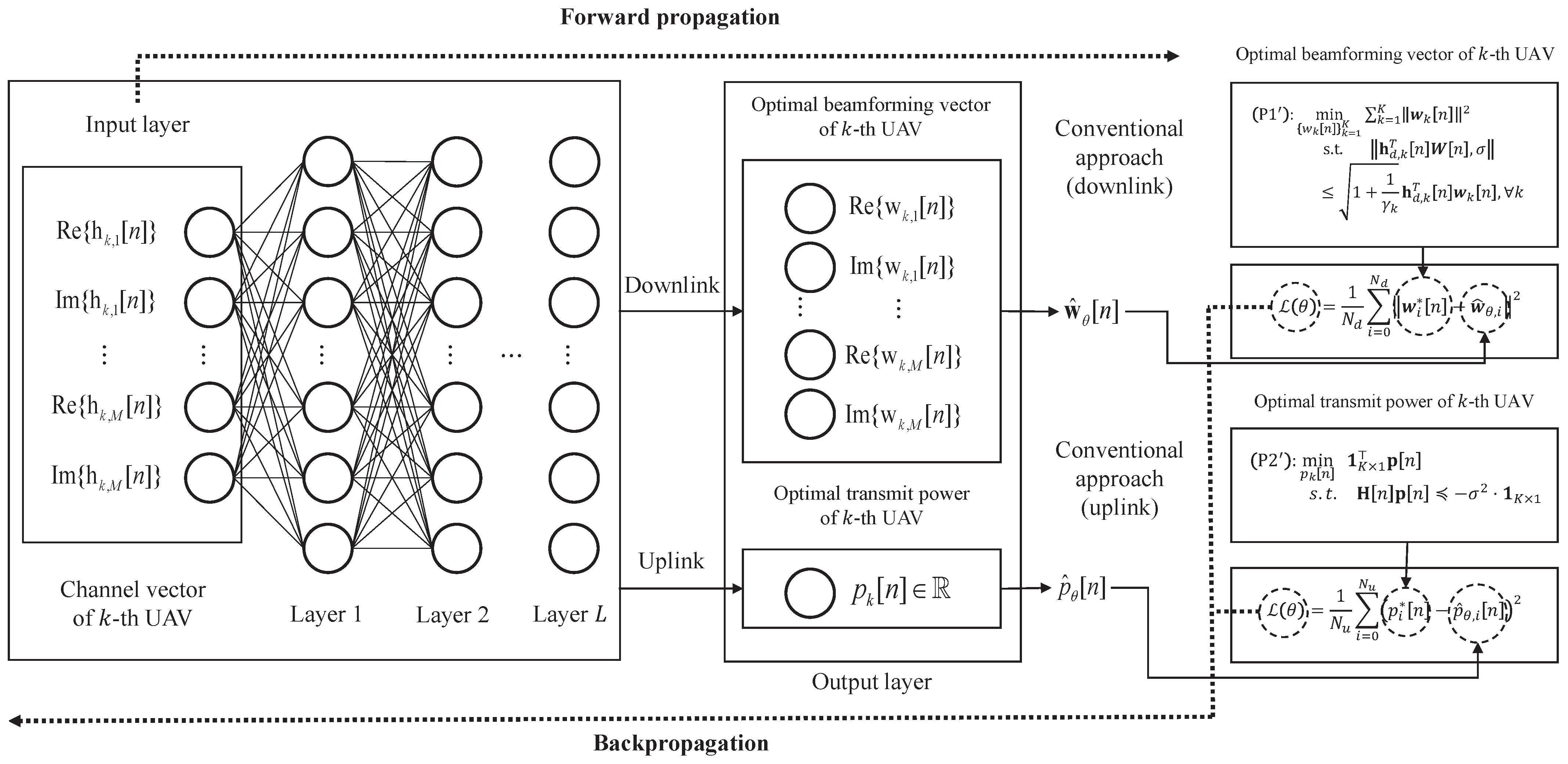
2.2.2. Network Architecture

The architecture of the constructed DNN is shown in Figure 2, of which goal is to efficiently compute (or predict) the solution to the problem (P1 ) in the downlink or (P2 ) in the uplink.
The constructed DNN uses the channel vector between the BS and the k-th UAV as the input and yields the optimal beamforming vector for the k-th UAV in the downlink scenario or optimal transmit power for the k-th UAV in the uplink scenario. Specifically, the input and output of the constructed DNN, respectively, are represented as
Input = [ Re h d , k [ n ] , Im h d , k [ n ] ] , for the downlink Re h u , k [ n ] , Im h u , k [ n ] ] , for the uplink Output = w ^ k , θ [ n ] , for the downlink p ^ k , θ [ n ] , for the uplink
where w ^ k , θ [ n ] and p ^ k , θ [ n ] are the estimate of the solutions to (P1 ) and (P2 ) for the k-th UAV, respectively.
The activation function decides whether or not a neuron will be activated or not and transferred to the next layer. It helps in the process of backpropagation because of their differentiable property. During the training process, the loss function is updated, and the activation function makes the gradient descent curves to achieve their local minima. We select the exponential linear unit (ELU) [28] as the activation function, which is a widely adopted activation function to alleviate various practical issues related to training (e.g., vanishing/exploding gradient [29] and dying ReLU problem [30]), which is given by
ELU ( x ) = x , if x > 0 μ ( exp ( x ) 1 ) , if x 0
where x denotes an input feature, and μ represents a hyperparameter that controls the saturation value.

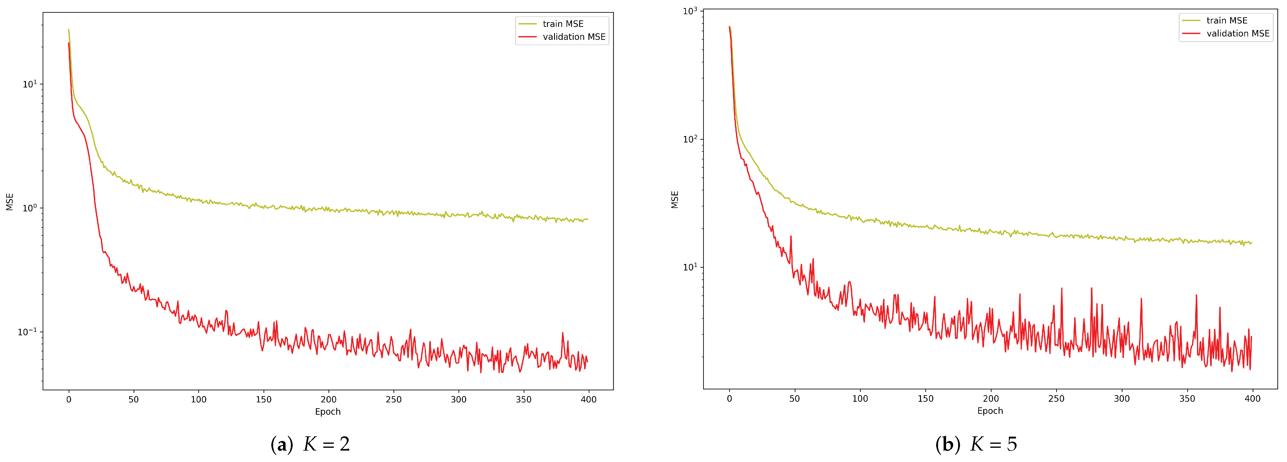
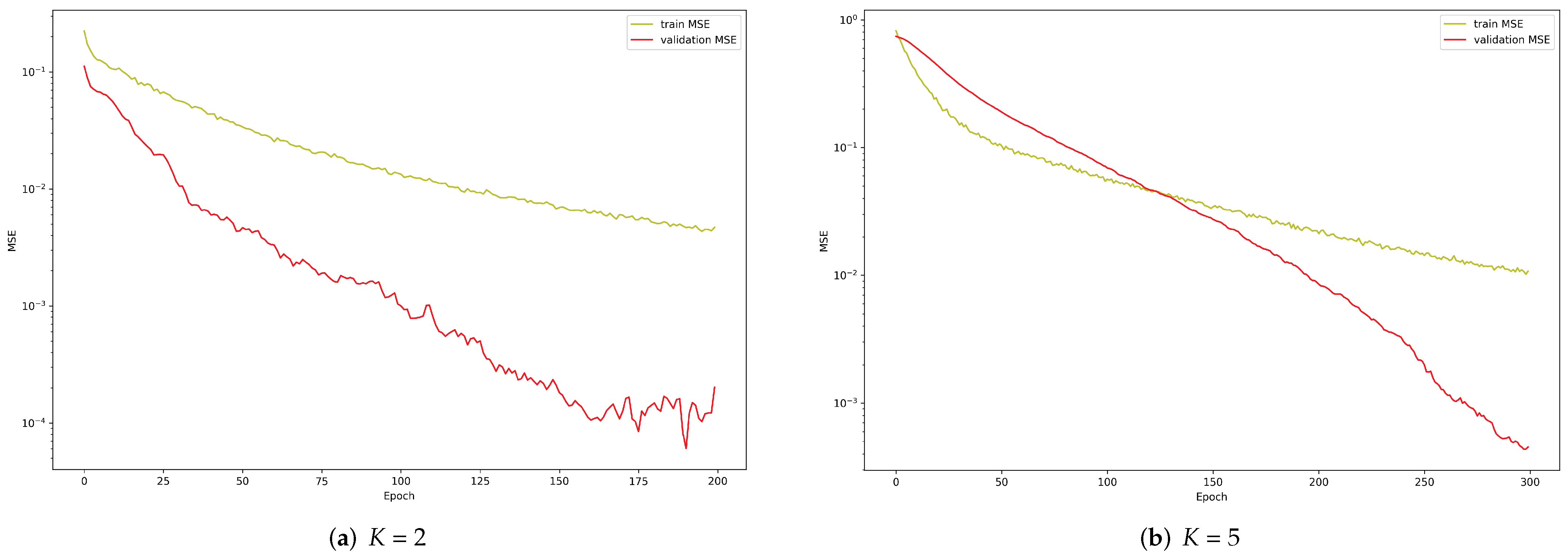
2.2.3. Training Procedure

The constructed DNN is trained in a supervised manner. Specifically, let w k [ n ] and p k [ n ] be the solutions to (P1 ) and (P2 ) for the k-th UAV, respectively. Then, for the training of the constructed DNN, we take the label as w k [ n ] in the downlink and p k [ n ] in the uplink.
For prediction with the minimum error, we select mean squared error (MSE) between the label and the output of the constructed DNN as the loss function as follows:
L ( θ ) = 1 N d i = 0 N d w i [ n ] w ^ θ , i [ n ] 2 , for the downlink 1 N u i = 0 N u p i [ n ] p ^ θ , i [ n ] 2 , for the uplink
where θ denotes the parameters of the constructed network. Additionally, N d , and N u denote the number of training samples for the downlink and the number of training samples for the uplink, respectively.
The weight update through the gradient descent is known to be effective and widely adopted [31]. The update rule of the gradient descent algorithm is described as follows:
θ t + 1 θ t α θ t L ( θ t )
where α > 0 is the learning rate, which determines the step size of the update.
For the UAV wireless communication, it is utmost important to realize good generalization behavior and fast convergence rate. Toward these goals, we adopt Nadam [31], which is a combination of nesterov accelerated gradient (NAG) [32] and adaptive moment estimation (Adam) [33] algorithm, in which the gradient can be expressed as
θ t + 1 θ t α v ^ t + ζ ( β m ^ t + ( 1 β ) θ t L ( θ t ) 1 β t )
where β , m ^ , and v ^ denote the decay rate of the first momentum vector, the bias-corrected first momentum vector, and the bias-corrected second momentum vector, respectively. Additionally, ζ is added to prevent the denominator from becoming zero (typically, set ζ = 1 × 10 6 ).

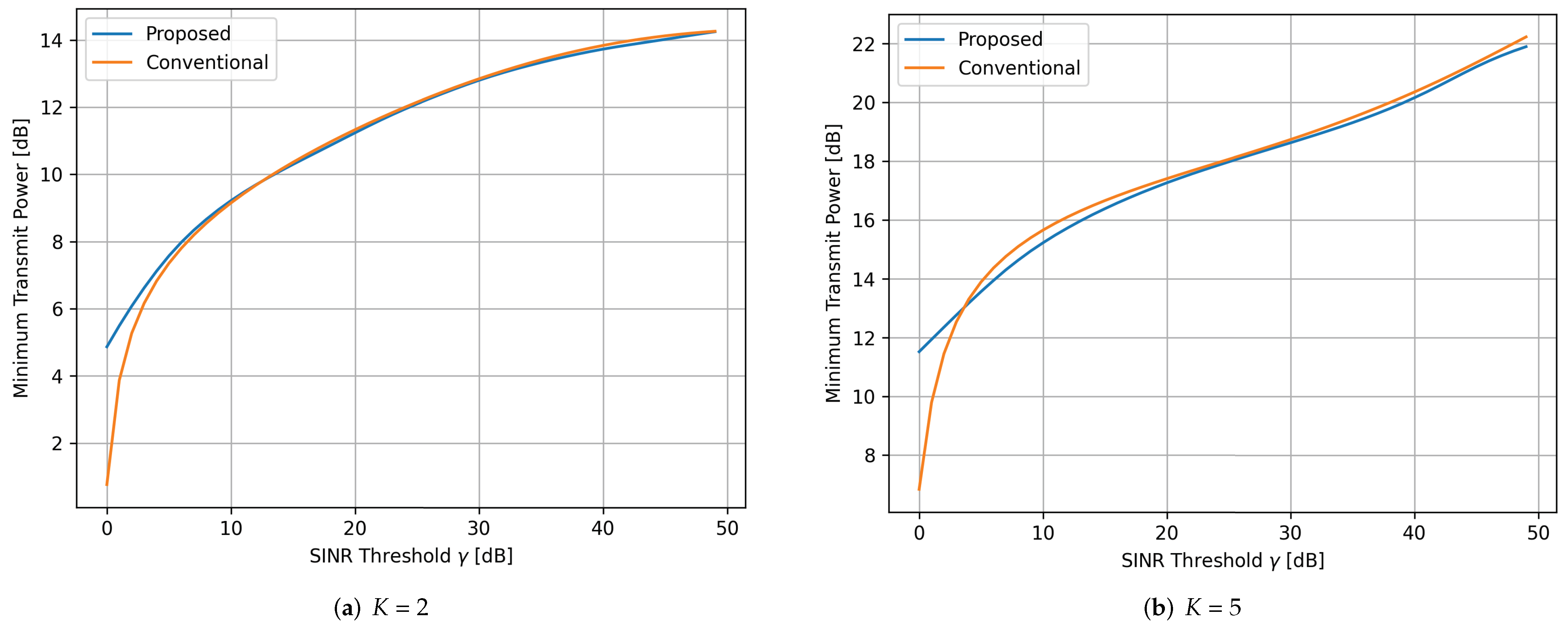
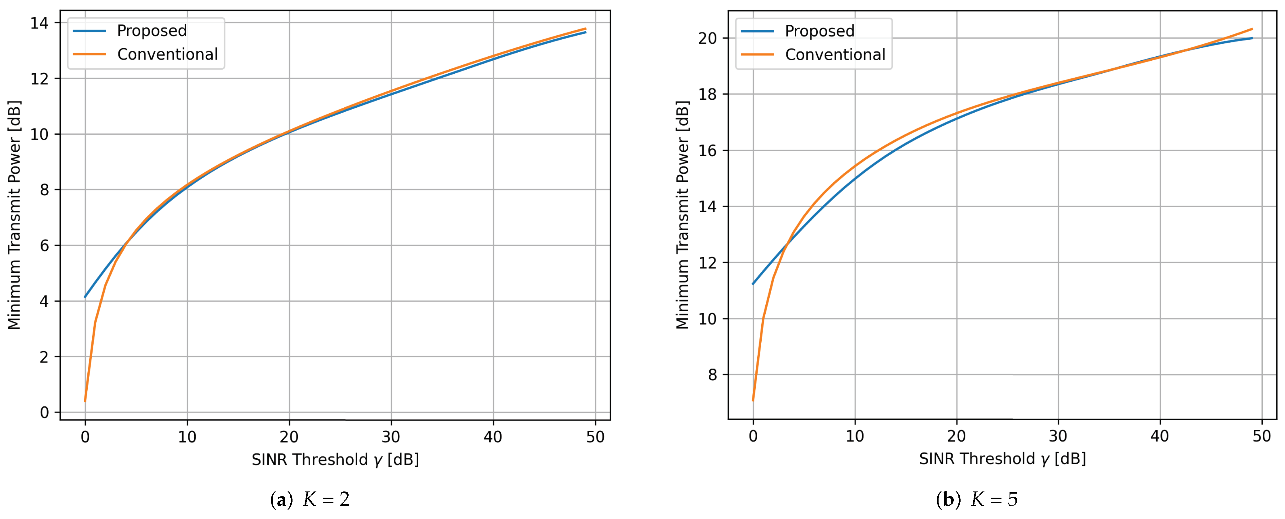
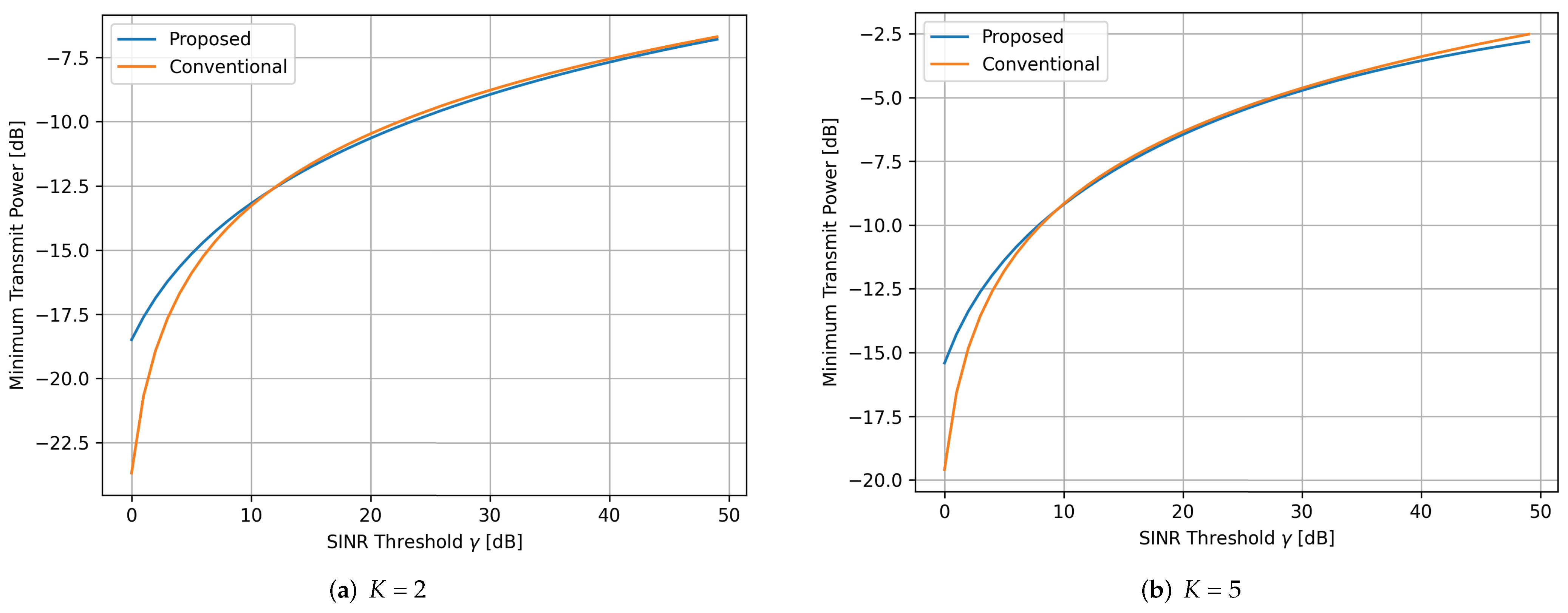
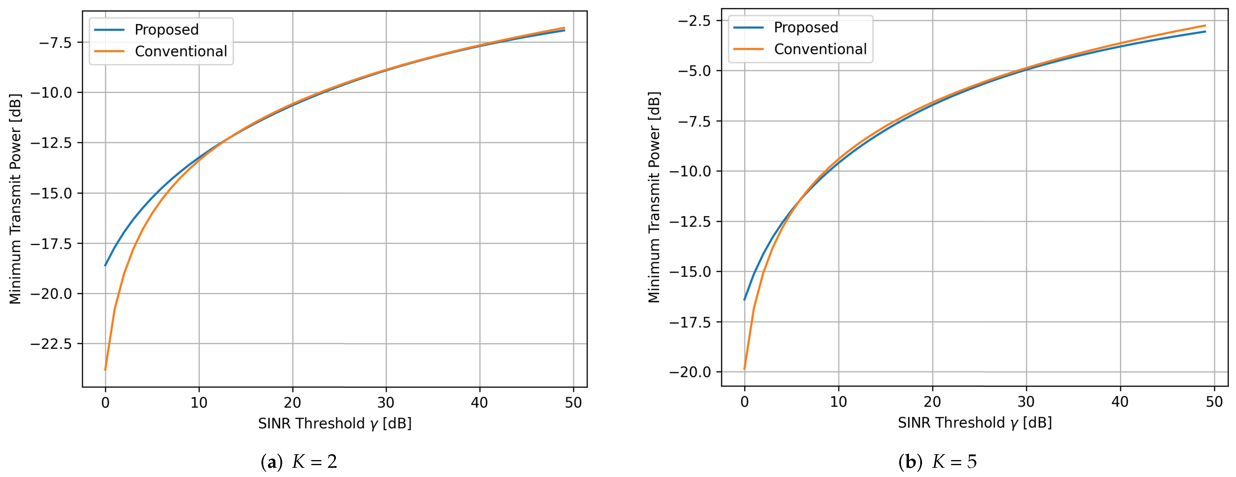
3. Numerical Results

In this section, we compare the performance of the proposed scheme to that of the conventional approaches through the numerical results. In the simulation, we consider the LoRa signals with B = 500 kHz and Rician fading channel model which is given by
h [ n ] = ( κ / ( 1 + κ ) ) ( 1 / 2 ) h LOS [ n ] + ( 1 / ( 1 + κ ) ( 1 / 2 ) h scatter [ n ]
with the K-factor set to κ = 13 dB , where the first term and the second term denote the line of sight (LOS) component and the scattering component, respectively. Additionally, the solutions to (P1 ) and (P2 ) are obtained via the MATLAB CVX solver [34]. The batch size and the learning rate for the proposed scheme are set to 1 and 0.01, respectively. In addition, the constructed DNN consists of three hidden layers each with 16, 32, and 16 nodes. The simulations are conducted in the range of 0 dB γ d , k 50 dB in the downlink and 0 dB γ u , k 0.5 dB in the uplink, respectively. Additionally, the velocities of all UAVs are set to be the same as v and the SINR threshold for both the downlink and uplink scenarios is set to γ = γ d , k = γ u , k , k .
In Figure 3, we plot the computational complexities of the conventional scheme and the proposed scheme with a fixed number of antennas of BS M = 32 . From Figure 3, we can observe that the proposed scheme has lower complexity than conventional optimization based scheme for each scenario.
In Figure 4, we plot learning curves of the proposed scheme in the downlink for K = 2 and K = 5, respectively, when the UAVs’ velocity v is set to 160 km/h. From Figure 4, we can observe that during the training and validation, the MSE (i.e., loss function) tends to decrease as the epoch increases, meaning that the proposed scheme learns the solution to (P1 ) well. Additionally, one can see that the MSE for the validation tends to be below the training curve due to the use of Dropout [35]. In the simulations, the dropout rates for each hidden layer L 1 , L 2 , and L 3 were set to 0.2, 0.3, and 0.3, respectively.
In Figure 5, the minimum transmit power is shown versus the SINR threshold γ for the downlink to compare the performance of the proposed scheme with the solution to (P1 ), where we set v = 160 km/h. From the Figure 5, we can observe that the constructed DNN accurately predicts the solution to (P1 ) over the entire regime of γ except for the low regime of γ .
Figure 6 shows the minimum transmit power versus the SINR threshold γ in the downlink for the same simulation setup as in Figure 5 except that v is set to 300 km/h. From the Figure 6, one can see the similar behaviors as in the Figure 5. Specifically, the constructed DNN is able to precisely approximate the solution to (P1 ) when the value of γ is between 10 dB and 50 dB, i.e., 10 dB γ 50 dB, while it tends to slightly overestimate the solution to (P1 ) when the value of γ is below 10 dB, i.e., γ < 10 dB. Additionally, From Figure 5 and Figure 6, we can further observe that the proposed scheme works robustly to the velocity variation of the UAVs, i.e., the predicted result well approximates the solution to (P1 ) regardless of the UAVs’ velocity.
In Figure 7, we plot the learning curves of the proposed scheme in the uplink when v = 160 km/h with K = 2 and K = 5 , respectively. From these results, one can see that the losses and MSEs of the proposed scheme gradually decrease. Additionally, for the same reason as in the Figure 4 (i.e., due to the use of Dropout), the validation curves tend to be below the training curves.
Figure 8 depicts the minimum transmit power versus the SINR threshold γ for the uplink when v = 160 km/h. From the Figure 8, one can see that the constructed DNN well approximates the solution to (P2 ) when 0.1 dB γ 0.5 dB while it tends to slightly overestimate when γ < 0.1 dB.
Figure 9 shows the performance of the proposed scheme in the uplink for the same simulation setup as in Figure 8 except that v is set to 300 km/h. From Figure 9, we can also observe that the constructed DNN precisely approximates the solution to (P2 ) when 0.1 dB γ 0.5 dB, while it tends to slightly overestimate the solution to (P2 ) otherwise.

4. Conclusions

In this paper, we proposed the universal and efficient DL-based scheme to predict the optimal beamforming vector in the downlink scenario or the transmit power allocation in the uplink scenario with very low computational complexity. We trained the constructed DNN to minimize the MSE-based loss function. The numerical results showed that the proposed scheme could precisely approximate the solutions (i.e., labels) with low computational complexity. An important future work for UAV wireless communications is to maximize the achievable rate using the proposed scheme.

Author Contributions

Conceptualization and methodology, Y.-R.K. and J.-H.P.; validation and formal analysis, Y.-R.K. and J.-H.P.; investigation and resources, D.-W.L. and K.-M.K.; writing—original draft preparation, Y.-R.K. and J.-H.P.; writing—review and editing, supervision, and project administration, J.-M.K. and D.-W.L. All authors have read and agreed to the published version of the manuscript.

Funding

This work was supported by the ICT R&D program of MSIT/IITP. [2019-0-00499, Development of Identification and Frequency Management Technology of Small Drones at Low Altitude].

Institutional Review Board Statement

Not applicable.

Informed Consent Statement

Not applicable.

Data Availability Statement

Not applicable.

Conflicts of Interest

The authors declare no conflict of interest.

Abbreviations

The following abbreviations are used in this manuscript:
AdamAdaptive Moment Estimation
BSBase Station
CSIChannel State Information
DLDeep Learning
DNNDeep Neural Network
ELUExponential Linear Unit
IoTInternet of Things
LoRaLong Range
LPLinear Programming
LPWANLow-Power Wide-Area Network
MSE       Mean Squared Error
NAGNesterov Accelerated Gradient
QoSQuality of Service
SFSpreading Factor
SINRSignal-to-Interference-plus-Noise Ratio
SOCPSecond-Order Cone Programming
UAVUnmanned Aerial Vehicle

References

  1. Shakhatreh, H.; Sawalmeh, A.H.; Al-Fuqaha, A.; Dou, Z.; Almaita, E.; Khalil, I.; Othman, N.S.; Khreishah, A.; Guizani, M. Unmanned aerial vehicles (UAVs): A survey on civil applications and key research challenges. IEEE Access 2019, 7, 48572–48634. [Google Scholar] [CrossRef]
  2. Zeng, Y.; Zhang, R.; Lim, T.J. Wireless communications with unmanned aerial vehicles: Opportunities and challenges. IEEE Commun. Mag. 2016, 54, 36–42. [Google Scholar] [CrossRef] [Green Version]
  3. Mozaffari, M.; Saad, W.; Bennis, M.; Nam, Y.H.; Debbah, M. A tutorial on UAVs for wireless networks: Applications, challenges, and open problems. IEEE Commun. Surv. Tutor. 2019, 21, 2334–2360. [Google Scholar] [CrossRef] [Green Version]
  4. Augustin, A.; Yi, J.; Clausen, T.; Townsley, W.M. A study of LoRa: Long range & low power networks for the internet of things. Sensors 2016, 16, 1466. [Google Scholar]
  5. Raza, U.; Kulkarni, P.; Sooriyabandara, M. Low power wide area networks: An overview. IEEE Commun. Surv. Tutor. 2017, 19, 855–873. [Google Scholar] [CrossRef] [Green Version]
  6. Kang, J.M.; Lim, D.W.; Kang, K.M. On the LoRa Modulation for IoT: Optimal Preamble Detection and Its Performance Analysis. IEEE Internet Things J. 2021, 9, 4973–4986. [Google Scholar] [CrossRef]
  7. Yu, W.; Lan, T. Transmitter optimization for the multi-antenna downlink with per-antenna power constraints. IEEE Trans. Signal Process. 2007, 55, 2646–2660. [Google Scholar] [CrossRef] [Green Version]
  8. Zhu, J.; Wang, J.; Huang, Y.; Navaie, K.; Ding, Z.; Yang, L. On optimal beamforming design for downlink MISO NOMA systems. IEEE Trans. Veh. Technol. 2020, 69, 3008–3020. [Google Scholar] [CrossRef]
  9. Huang, Y.; Zhou, L. MISO NOMA downlink beamforming optimization with per-antenna power constraints. Signal Process. 2021, 179, 107828. [Google Scholar] [CrossRef]
  10. Van Chien, T.; Björnson, E.; Larsson, E.G. Joint power allocation and user association optimization for massive MIMO systems. IEEE Trans. Wirel. Commun. 2016, 15, 6384–6399. [Google Scholar] [CrossRef] [Green Version]
  11. Zuo, H.; Tao, X. Power allocation optimization for uplink non-orthogonal multiple access systems. In Proceedings of the 2017 9th International Conference on Wireless Communications and Signal Processing (WCSP), Nanjing, China, 11–13 October 2017; pp. 1–5. [Google Scholar] [CrossRef]
  12. Tan, F.; Lv, T.; Yang, S. Power allocation optimization for energy-efficient massive MIMO aided multi-pair decode-and-forward relay systems. IEEE Trans. Commun. 2017, 65, 2368–2381. [Google Scholar]
  13. Huang, H.; Peng, Y.; Yang, J.; Xia, W.; Gui, G. Fast beamforming design via deep learning. IEEE Trans. Veh. Technol. 2019, 69, 1065–1069. [Google Scholar] [CrossRef]
  14. Luijten, B.; Cohen, R.; de Bruijn, F.J.; Schmeitz, H.A.; Mischi, M.; Eldar, Y.C.; van Sloun, R.J. Deep learning for fast adaptive beamforming. In Proceedings of the ICASSP 2019—2019 IEEE International Conference on Acoustics, Speech and Signal Processing (ICASSP), Brighton, UK, 12–17 May 2019; pp. 1333–1337. [Google Scholar]
  15. Xie, B.; Yin, Y.; Xiong, J. Pushing the Limits of Long Range Wireless Sensing with LoRa. Proc. ACM Interact. Mob. Wearable Ubiquitous Technol. 2021, 5, 1–21. [Google Scholar] [CrossRef]
  16. Nguyen, T.T.; Nguyen, H.H.; Barton, R.; Grossetete, P. Efficient design of chirp spread spectrum modulation for low-power wide-area networks. IEEE Internet Things J. 2019, 6, 9503–9515. [Google Scholar] [CrossRef]
  17. Vangelista, L. Frequency Shift Chirp Modulation: The LoRa Modulation. IEEE Signal Process. Lett. 2017, 24, 1818–1821. [Google Scholar] [CrossRef]
  18. Chiani, M.; Elzanaty, A. On the LoRa Modulation for IoT: Waveform Properties and Spectral Analysis. IEEE Internet Things J. 2019, 6, 8463–8470. [Google Scholar] [CrossRef] [Green Version]
  19. Bernier, C.; Dehmas, F.; Deparis, N. Low complexity LoRa frame synchronization for ultra-low power software-defined radios. IEEE Trans. Commun. 2020, 68, 3140–3152. [Google Scholar] [CrossRef] [Green Version]
  20. Xhonneux, M.; Bol, D.; Louveaux, J. A low-complexity synchronization scheme for LoRa end nodes. arXiv 2019, arXiv:1912.11344. [Google Scholar]
  21. Ghanaatian, R.; Afisiadis, O.; Cotting, M.; Burg, A. LoRa digital receiver analysis and implementation. In Proceedings of the ICASSP 2019—2019 IEEE International Conference on Acoustics, Speech and Signal Processing (ICASSP), Brighton, UK, 12–17 May 2019; pp. 1498–1502. [Google Scholar]
  22. Schubert, M.; Boche, H. Solution of the multiuser downlink beamforming problem with individual SINR constraints. IEEE Trans. Veh. Technol. 2004, 53, 18–28. [Google Scholar] [CrossRef]
  23. Björnson, E.; Bengtsson, M.; Ottersten, B. Optimal Multiuser Transmit Beamforming: A Difficult Problem with a Simple Solution Structure [Lecture Notes]. IEEE Signal Process. Mag. 2014, 31, 142–148. [Google Scholar] [CrossRef] [Green Version]
  24. Li, Y.; Jiang, M.; Zhang, Q.; Qin, J. Joint beamforming design in multi-cluster MISO NOMA reconfigurable intelligent surface-aided downlink communication networks. IEEE Trans. Commun. 2020, 69, 664–674. [Google Scholar] [CrossRef]
  25. Luo, Z.Q.; Yu, W. An introduction to convex optimization for communications and signal processing. IEEE J. Sel. Areas Commun. 2006, 24, 1426–1438. [Google Scholar]
  26. Morin, T.; Prabhu, N.; Zhang, Z. Complexity of the gravitational method for linear programming. J. Optim. Theory Appl. 2001, 108, 633–658. [Google Scholar] [CrossRef]
  27. Freire, P.J.; Osadchuk, Y.; Spinnler, B.; Napoli, A.; Schairer, W.; Costa, N.; Prilepsky, J.E.; Turitsyn, S.K. Performance versus complexity study of neural network equalizers in coherent optical systems. J. Light. Technol. 2021, 39, 6085–6096. [Google Scholar] [CrossRef]
  28. Clevert, D.A.; Unterthiner, T.; Hochreiter, S. Fast and accurate deep network learning by exponential linear units (elus). arXiv 2015, arXiv:1511.07289. [Google Scholar]
  29. Bengio, Y.; Simard, P.; Frasconi, P. Learning long-term dependencies with gradient descent is difficult. IEEE Trans. Neural Netw. 1994, 5, 157–166. [Google Scholar] [CrossRef]
  30. Lu, L.; Shin, Y.; Su, Y.; Karniadakis, G.E. Dying relu and initialization: Theory and numerical examples. arXiv 2019, arXiv:1903.06733. [Google Scholar] [CrossRef]
  31. Ruder, S. An overview of gradient descent optimization algorithms. arXiv 2016, arXiv:1609.04747. [Google Scholar]
  32. Botev, A.; Lever, G.; Barber, D. Nesterov’s accelerated gradient and momentum as approximations to regularised update descent. In Proceedings of the 2017 International Joint Conference on Neural Networks (IJCNN), Anchorage, AK, USA, 14–19 May 2017; pp. 1899–1903. [Google Scholar]
  33. Kingma, D.P.; Ba, J. Adam: A method for stochastic optimization. arXiv 2014, arXiv:1412.6980. [Google Scholar]
  34. Grant, M.; Boyd, S. CVX: Matlab Software for Disciplined Convex Programming, Version 2.1; 2014. Available online: http://cvxr.com/cvx/citing/ (accessed on 17 April 2022).
  35. Srivastava, N.; Hinton, G.; Krizhevsky, A.; Sutskever, I.; Salakhutdinov, R. Dropout: A simple way to prevent neural networks from overfitting. J. Mach. Learn. Res. 2014, 15, 1929–1958. [Google Scholar]
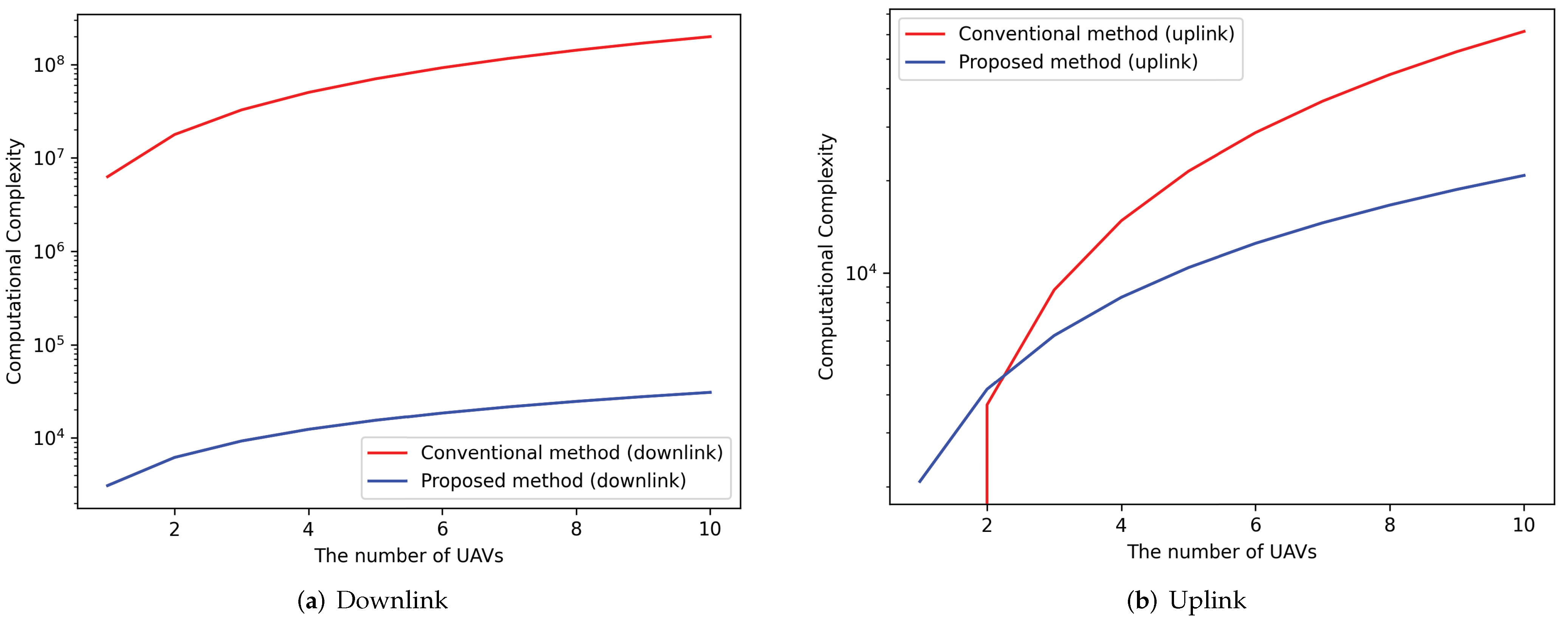
Figure 1. System models for UAV wireless communications.
Applsci 12 04826 g001
Figure 2. The network structure and loss function of the proposed scheme.
Applsci 12 04826 g002
Figure 3. Computational complexities of the conventional scheme and the proposed scheme.
Applsci 12 04826 g003
Figure 4. Learning curve of the proposed scheme for the downlink with v = 160 km/h.
Applsci 12 04826 g004
Figure 5. Minimum transmit power versus the SINR threshold for the downlink with v = 160 km/h.
Applsci 12 04826 g005
Figure 6. Minimum transmit power versus the SINR threshold for the downlink with v = 300 km/h.
Applsci 12 04826 g006
Figure 7. Learning curve of the proposed scheme for the uplink with v = 160 km/h.
Applsci 12 04826 g007
Figure 8. Minimum transmit power versus the SINR threshold for the uplink with v = 160 km/h.
Applsci 12 04826 g008
Figure 9. Minimum transmit power versus the SINR threshold for the uplink with v = 300 km/h.
Applsci 12 04826 g009
Table 1. Computational complexities for the various M , K pairs in the uplink.
M , K Conventional Scheme (Uplink)Proposed Scheme
4 , 6 4487104
8 , 6 17937872
16 , 8 11,09712,544
32 , 8 44,38916,640
64 , 10 245,76031,040
128 , 10 983,04051,520
Table 2. Computational complexities for the various M , K pairs in the downlink.
M , K Conventional Scheme (Downlink)Proposed Scheme
4 , 6 22,57456,832
8 , 6 361,192125,952
16 , 8 8,897,462401,408
32 , 8 142,359,3981,064,960
64 , 10 3,183,252,9213,973,120
128 , 10 50,930,046,74213,189,120
Publisher’s Note: MDPI stays neutral with regard to jurisdictional claims in published maps and institutional affiliations.

