Abstract
Carbon nanotube (CNT) yarn sensors were embedded in 3D braided composites in the form of arrays to detect the internal damage of specimens and study the internal damage monitoring of the 3D braided composites. The signals collected by the sensor array of CNT yarn were preprocessed using the dynamic wavelet threshold algorithm. The exact position of the damage was calculated based on the main features of the resistance signal matrix, which was calculated using the quadratic matrix singular value. The results show that the internal damage localization of the specimens was consistent with the actual damage. The localizations in this study can provide a basis for enhancing the structural health monitoring of smart 3D braided composites.
1. Introduction
Using the method of multiaxial orientation, integral braiding endows 3D braided composites a spatial network interlocking structure. This structure overcomes the shortcomings of traditional compound-material laminates, namely, poor interlayer performance and impact resistance [1]. The process can directly braid special specimens in accordance with the parts of shapes and dimensions, such as truncated cone shape, dumbbell, and ribbed cylinder, without seaming and processing. It creates conditions for achieving complex shapes from the entire design and manufacturing. The technology has been successfully applied to the manufacturing of components in aeronautics, space industry, sporting goods, ships, and biological materials [2]. Bearing materials are affected by aging, high pressure, high temperature, and corrosion at high altitudes and tend to exhibit fatigue and damage under the combined action of various complex loads [3].
Current methods of damage detection of composite materials include visual detection, X-ray detection, acoustic emission detection, ultrasonic testing, eddy current, ray, and fiber Bragg grating [4]. These methods usually require complex equipment and online real-time monitoring, and the structure and location of the damage need to be determined initially. Thus, these methods are difficult to use and have serious limitations [5].
A recent study of the application of carbon nanotube (CNT) yarn as a resistance sensor resulted in the development of CNT yarn sensors based on different sensing principles [6]. Abot, Jandro L. Kiyono, and César Y. analyzed the piezoresistive properties of CNT yarn sensors that can be integrated into polymers and composites without increasing or altering the weight. With regard to the integrity of the main material, the composite strain was analyzed by measuring CNT yarn resistance, and the structure and piezoresistive response of the new strain sensor were investigated. Studies have shown that strain gauges composed of CNT yarn are more sensitive than metal foil strain gauges and thus suitable for various strain measurements [7]. Spellauge M., Loghin F. C., and other researchers achieved significant de-bundling of the network by operating the laser below the ablation threshold. More importantly, they used linearly polarized laser pulses to selectively ablate a single-walled carbon nanotube (SWCNT) that is parallel to the direction of polarization of the incident laser, creating aligned anisotropic conductivity networks. This research has created opportunities for the application of SWCNT in the field of electronics [8]. Loghin F., Rivadeneyra A., and other researchers proposed ink preparation and post-treatment solutions, which can be used as a simple and effective platform for the future preparation of high-quality and residue-free SWCNT films. In order to demonstrate the feasibility of the study, they prepared and characterized the gas sensor with CNT films as sensor material, the screen-printed silver-based films as the interdigital electrode (IDE) structure, and the polyimide as a flexible and solid substrate [9].
Alexopoulos N.D., Bartholome C., and other researchers embedded polyvinyl alcohol (PVA) CNT yarn in glass-fiber-reinforced plastic composites for the strain monitoring of composite materials. They analyzed a specimen’s tensile and internal damage under a three-point bending load by measuring the embedded CNT yarn resistance [10]. Shang Yuanyuan, He Xiaodong, and other researchers used single-walled CNT yarn to fabricate different structural multifunctional sensors that produce large deformations (90% stretch shrink) and unique features. Compared with multi-walled carbon nanotube (MWCNT) yarn, SWCNT yarn can be used as structural specimens of large deformation monitoring sensors [11]. Abu Obaid A., Heider, and other researchers evaluated a CNT yarn sensor and studied its mechanical (toughness and failure strain) and electrical (resistivity and specification factor) properties under a uniaxial tensile load. The results of their cyclic loading test showed that the relative resistance change during loading is linear strain, and the sensor can be used in the health monitoring of composite structure states [12].
On the basis of this analysis, this study investigates strain detection and damage identification technology of 3D braided composites by using a CNT yarn sensor. Threshold data are used to denoise the original data and improve the damage detection rate and positioning accuracy. The data matrix is reduced and extracted by quadrature singular value decomposition (SVD). The data processing capacity is reduced, and the real-time measurement is achieved.
2. Materials and Methods
2.1. Embedding Mode of the CNT Yarn Sensor
CNT yarn sensors were braided together with carbon fibers to form 3D six-directional preforms and solidified via resin transfer molding. Through 3D and six-directional braiding using a four-step braiding technology, a preform was produced based on 3D five-directional braided fabric that was processed at a reinforcing rate of 1:1. The braiding yarns is carried by the yarn carrier and arranged in a certain cross section. The main yarn carriers were arranged in the m-line and n-column main body arrays. The array between the braided yarn and the five-axis yarn was identical to the array of the five-way braid with the same structural parameters. The other preforms were arranged in the same manner.
Figure 1 shows the arrangement of 5 × 4 3D six-directional preforms and five-directional shafts on the braiding machine chassis. In Figure 1, × represents a carrier for hanging five-directional yarn, and ○ is a carrier for hanging braiding yarn. The number in ○ indicates the coordinate of the braiding yarn in the braiding machine chassis. The movement of the yarn of the braiding yarn is carried out by the alternating movement of the rows and columns, each of which carries a woven yarn that is carried out by a four-step intermittent motion of rows and columns. In the first step, adjacent rows are staggered with one another. In the second step, the adjacent columns move from each other. The third and fourth steps are contrary to the first and second steps, and four steps complete a machine cycle. During the braiding process, the fifth yarn remains substantially fixed, and the sixth yarn is added between adjacent rows after the second and fourth steps of movement, as shown by the dotted line in Figure 1. The length of the preform obtained in a machine cycle is defined as the length of the node. By repeating the braiding step, the braiding yarn binds the fifth and sixth yarn together to form a final 3D six-direction braided preform.
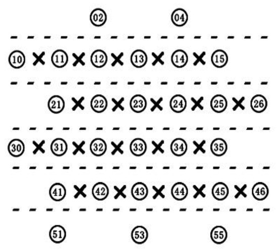
Figure 1.
Arrangement of 3D six-directional braiding yarn.
Figure 2 presents a computer simulation of the four-step braiding process involving 3D six-direction braiding technology. Figure 2 shows that the CNT yarn is in a straight state in the 3D composites. A CNT yarn was set as the axial yarn at a certain number of knitting yarns to monitor the load bearing of the intelligent 3D braided composite parts. The CNT yarn used as axial yarn in this work were provided by the Suzhou Institute of Nanotechnology and Nano Biology Institute of the Chinese Academy of Sciences. Continuous monitoring of the overall load of the 3D braided composite material can be achieved because the CNT yarn sensors are continuous during the braiding process.
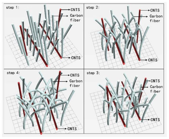
Figure 2.
Computer simulation of 3D six-directional braiding technology.
The health monitoring system of 3D braided composite materials based on the CNT yarn sensor structure is shown in Figure 3. In this structure system, the strain data of the CNT yarn sensing array are read by the multi-channel Wheatstone bridge, which can realize strain monitoring of the 3D braided composite parts through the sensing characteristics of the CNT yarn and real-time measurement.
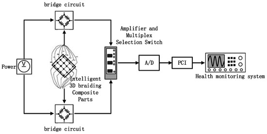
Figure 3.
Damage detection system of the 3D braided composite.
2.2. Damage Algorithm Based on SVD
2.2.1. Construction of the Decomposition Matrix of the CNT Yarn
The premise and basis of structural damage identification based on SVD form a matrix for SVD. The CNT yarn embedded in the 3D braided composite specimen are distributed in an array, but each CNT yarn is continuous inside the material and can be collected only at its end point. This condition means that CNT yarn is actually used for the carbon nanotube yarn array of m-rows and n-columns, and a resistance value (m-row and n-column values) can be measured. In this study, the weighted average method was used to construct a resistance matrix by using row and column values.
Assuming that the test piece is divided into m + n points (small area) by the CNT yarn, as shown in Figure 4, the coordinates of each point can be expressed by (i,j) on the basis of the previous analysis. The magnitude is determined by the resistance of the line at which the point is located and the resistance of the column. The magnitude of the resistance is proportional to the load on the point, and the contribution of row resistance and column resistance to the point value is the same. Hence, the coordinates of position (i,j) of the resistance can be obtained by Equation (1).
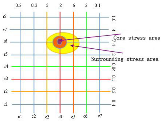
Figure 4.
Distribution of loading for CNT yarn.
We determined the values of the sensor array in a 2D matrix.
where m represents the number of rows, n represents the number of columns, and the matrix element represents the sensor resistance at the point of coordinates where the surface of the specimen is (i,j).
The matrix is normalized so that all element values are between 0 and 1. The numerical matrix is similar to the grayscale image matrix. It can be processed by the image-based 2D wavelet denoising method. The numerical matrix is denoised after denormalization.
The wavelet threshold denoising algorithm is divided into four steps, as follows:
Step 1: Select a wavelet basis function to determine the number of wavelet decompositions of the signal;
Step 2: Determine the threshold. The wavelet threshold λ plays a decisive role in the denoising process. If the threshold is too small, the system will use soft threshold estimates based on unbiased likelihood estimates;
Step 3: Select the software threshold function to threshold the wavelet coefficients, namely:
Step 4: Reconstruct the wavelet. On the basis of the high-frequency wavelet coefficients after thresholding and the untreated low-frequency wavelet coefficients, the signal is reconstructed by discrete wavelet transform.
2.2.2. Damage Location Based on Matrix SVD
The SVD decomposition of the CNT yarn resistance matrix was carried out based on SVD and the characteristic orthogonal decomposition method. The SVD of the CNT yarn resistance matrix proceeds as
where A is the matrix of m + n. The SVD algorithm can decompose matrix A into three parts, where U is the orthogonal matrix of m + n, is the orthogonal matrix, is a diagonal matrix, and r is the rank of matrix A. is the singular value of matrix A.
In this study, the SVD algorithm was used to decompose the singular value of the resistance data matrix collected by the carbon nanotube yarn sensors, and all the hidden features in the original data matrix were extracted. The highly important hidden features were selected to construct a low-dimensional feature space, and the resistance data were reprojected onto the low-dimensional feature space to complete the matrix dimensionality reduction process and reduce the amount of data calculation.
In the damage detection of composite materials, the damage part is only part of the entire specimen, and a large difference in the data matrix exists between the damaged and healthy area. Therefore, the data matrix is automatically segmented to identify the sensitive area with damage. The data of the non-damaged sub-matrix are set to zero to reduce the amount of data calculation and improve the calculation speed. The system is based on the quadratic matrix SVD algorithm for analyzing the damage location of the specimen. The quadratic matrix SVD process is shown in Figure 5. Figure 6 presents a flow chart of the quadratic matrix SVD algorithm.
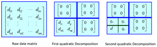
Figure 5.
Sketch of SVD of a four-block matrix.
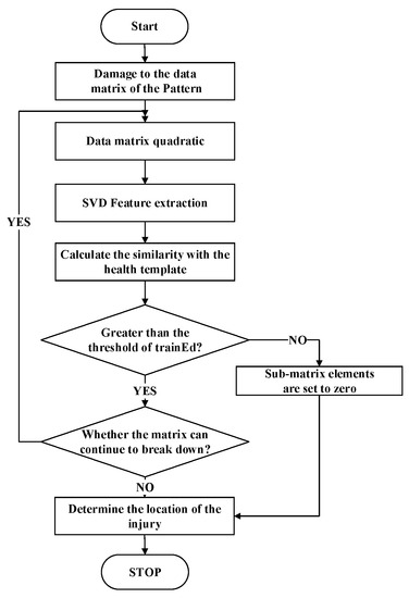
Figure 6.
Flow chart of the SVD algorithm of the four-block matrix.
3. Results and Discussion
Different damage information needs to be monitored in the experiment. By analyzing the change in the resistance data of a carbon nanosensor in the material after damage, the existence and type of damage can be determined, and the location of damage can be inferred.
All the specimens used in the experiment were prepared by the Institute of Composite Materials, Tianjin University of Technology. Five 3D braided composite specimens with CNT yarn were selected to study the effect of CNT yarn on the internal damage of 3D braided composites. The experimental specimens were rectangular plates with a size of 250 mm × 25 mm × 4 mm. The relevant parameters of the test pieces are shown in Table 1, and the specimen shape is shown in Figure 7.

Table 1.
Material number and parameters.
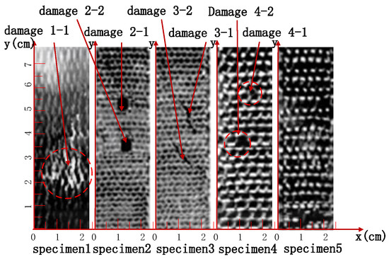
Figure 7.
The 3D six-directional braided composite specimens.
Specimen 5 was a healthy 3D braided composite material. Specimen 1 had a shock damage caused by an Instron Dynatup9250HV-type load-down impact testing machine produced by the YingSiTe Company. The experiment used a hemispherical hammer with a diameter of 12.7 mm and a drop weight of 6.5 kg. Two damage points were set in Specimens 2 and 3 to fully verify the damage location accuracy. Specimen 2 had two circular hole-like damages with a diameter of 5 mm. Damage 3-1 in Specimen 3 was a 1D linear damage with a length of 12.8 mm and a horizontal 52.3 degree. The projection length of this damage was 10.13 mm in the longitudinal direction and 7.83 mm in the transverse direction. Damage 3-2 was 1D linear damage with a length of 10.3 mm and a horizontal 46.7 degree. The projection of the damaged straight line was 7.06 mm in the horizontal direction and 7.23 mm in the vertical direction. Specimen 4 was a composite specimen with a small defect inside.
The data of the four specimens were sampled, and the 2D wavelet denoising method was used to denoise the strain signal. The data before and after noise reduction are shown in Figure 8. The data obtained by the sensor of Specimen 1 in Figure 8a had two abnormal mutations, indicating that two lesions were detected. Figure 8b is similar to Figure 8a, and both damages in Specimen 2 were detected before and after noise reduction. Figure 8c shows no significant anomalies in the data before noise reduction, indicating that the minor defects in Specimen 3 were not detected in the data before noise reduction. An anomaly in the processed data can be seen on the noise reduction line in Figure 8d. Figure 8d indicates that an anomaly was detected before and after denoising.
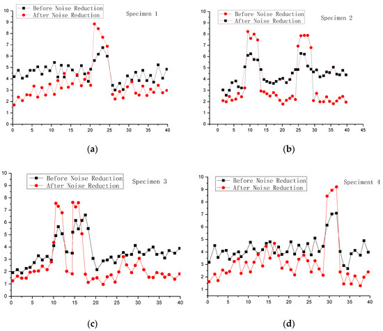
Figure 8.
Comparison of signal sensitivity to four kinds of damage before and after noise reduction: (a) one shock damage, (b) two circular hole-like damages, (c) two 1D linear damages, (d) two small defects inside.
The 2D image of the healthy Specimen 5 was used as a template, and the corresponding data matrix was divided into m sub-regions. The feature data of the data matrix after the noise reduction of the tested damaged specimen were decomposed, and the internal damage position of the specimen was measured using the method in Figure 6.
The maximum and minimum rows of the resistance values detected in the definition test were greater than the set thresholds and , and the maximum and minimum columns were and , respectively. The damage position coordinates are denoted by , as follows:
where On(0, 0) represents the origin coordinates of the specimen numbered n.
The coordinate deviation was calculated from the formula, where represents the actual abscissa of the injured position, represents the abscissa of the injured position, represents the actual ordinate of the injured position, and represents the ordinate of the damage position.
Table 2 shows the damage location in Specimen 1 to Specimen 4 calculated with the quadrilateral matrix SVD method. The damages of the specimen were scanned using the industrial CT system, and the actual positions of the internal damages of the specimens were obtained.
Table 2.
Comparison of the measured damage location coordinate and the actual one.
Damage 1-1 is the uneven dent caused by the impact of a heavy hammer on the test piece. Because there is a certain deviation in the actual measurement value of the damage coordinate, and there is also a certain deviation between the damage position detected by the CNT yarn sensor and the actual damage position, the deviation between the damage calculation coordinate and the damage actual coordinate reaches 0.71 mm. Damages 3-1 and 3-2 are irregular cracks. The deviation between the damage calculation coordinates and the actual damage coordinates is also 0.76 mm and 0.32 mm, respectively. Damages 2-1 and 2-2 are regular round holes. Because the actual measurement values of the damage coordinates are relatively accurate, and the CNT yarn sensor has a high detection accuracy for uniform damage, the deviation between the damage calculation coordinates and the actual damage coordinates is relatively small, which are 0.28 mm and 0.45 mm; respectively. Damage 4-2 is a conventional implant defect, and the deviation between the calculated coordinates of the damage and the actual coordinate of the damage is only 0.1 mm.
In conclusion, the error value of the measurement was less than 1 mm, which indicates that the method established in this study is suitable for the internal damage monitoring of composite materials. After wavelet denoising, the CNT yarn sensor could accurately reflect the damage state of the 3D composite structure. However, for the minor flaws (damage 4-1), missed detection was observed due to the structurally embedded CNT yarn density and other factors.
4. Conclusions
CNT yarn has an excellent electromechanical performance and was applied to the damage detection of 3D braided composite specimens. CNT yarn was embedded into a composite specimen via a 3D, four-step, six-direction braiding process. The CNT yarn of five-direction and six-direction yarn was kept in a straight state. Estimating the location of internal damage based on the change in the resistance value of CNT yarn was determined to be a feasible means of monitorization.
The signal of the CNT yarn embedded into the specimen structure included information on strain (stress) and the size and location of the damage. The quadratic matrix SVD algorithm was used to simplify the data and improve the efficiency of the algorithm. In accordance with the key characteristics of the matrix, the existence of damage was determined by calculating the eigenvalue of the healthy specimen, and the damage position was determined.
The experimental results showed that the 2D wavelet threshold denoising method is useful for the damage recognition effect and the damage recognition rate. The quadrature matrix SVD algorithm exhibited high positioning accuracy, and the measured coordinate error value was less than 1 mm.
Author Contributions
Conceptualization, Z.W.; methodology, M.J. and Z.W.; investigation, M.J. and Z.W.; writing-original draft preparation, M.J. and Z.W.; writing-review and editing, M.J.; supervision, Z.W.; project administration, Z.W.; funding acquisition, Z.W. All authors have read and agreed to the published version of the manuscript.
Funding
A research project funded by the Doctoral Program Fund of the Ministry of Education of China (200800580004).
Data Availability Statement
The data presented in this study are available on request from the corresponding authors. The data are not publicly available due to lack of adequate repository.
Conflicts of Interest
The authors declare no conflict of interest.
References
- Jiao, Y.; Li, J. Manufacturing engineering and mechanical. Tech. Text. 1989, 89, 26–29. [Google Scholar]
- Feng, D.; Shang, Y.; Li, J. Multi-scale Simulation of Impact Fracture Behavior of 4- & 5-Direction 3D Composite Material. J. Text. Res. 2020, 41, 67–73. [Google Scholar]
- Yuan, S.; Qiu, L.; Wu, J.; Sun, Y.; Wang, Q. Challenge in Structural Health Monitoring of Large Aircraft Development. Aeronaut. Manuf. Technol. 2009, 22, 62–67. [Google Scholar]
- Zhou, Z.; Sun, G.; Li, Y. Application of advanced nondestructive testing technologies for the detection of defects in composites. Aeronaut. Manuf. Technol. 2016, 4, 30–35. [Google Scholar]
- Hetti, M.; Wei, Q.; Pohl, R.; Casperson, R.; Bartusch, M.; Neu, V.; Pospiech, D.; Voit, B. Magnetite core-shell nanoparticles in nondestructive flaw detection of polymeric materials. ACS Appl. Mater. Interfaces 2016, 8, 28208–28215. [Google Scholar] [CrossRef] [PubMed]
- Huo, D.; Luo, W.; Hou, W.; Luo, X. FA Huanbao, etal.Research progress of electro spun nano fibers in sensor field. Transducer Microsyst. Technol. 2009, 28, 4–7. [Google Scholar]
- Abot, J.L.; Kiyono, C.Y.; Thomas, G.P.; Silva, E.C. Strain gauge sensors comprised of carbon nanotube yarns:Parametric numerical analysis of their piezoresistive response. Smart Mater. Struct. 2015, 24, 075018. [Google Scholar] [CrossRef]
- Spellauge, M.; Loghin, F.C.; Sotrop, J.; Domke, M.; Bobinger, M.; Abdellah, A.; Becherer, M.; Lugli, P.; Huber, H.P. Ultra-short-pulse laser ablation and modification of fully sprayed single walled carbon nanotube networks. Carbon 2018, 138, 234–242. [Google Scholar] [CrossRef]
- Loghin, F.; Rivadeneyra, A.; Becherer, M.; Lugli, P.; Bobinger, M. A Facile and Efficient Protocol for Preparing Residual-Free Single-Walled Carbon Nanotube Films for Stable Sensing Applications. Nanomaterials 2019, 9, 471. [Google Scholar] [CrossRef] [PubMed] [Green Version]
- Alexopoulos, N.D.; Bartholome, C.; Poulin, P. Damage detection of glass fiber reinfiorced composites using embedded PVA-carbon nanotube (CNT) fibers. Compos. Sci. Technol. 2010, 70, 1733–1741. [Google Scholar] [CrossRef] [Green Version]
- Shang, Y.; He, X.; Wang, C.; Zhu, L.; Peng, Q.; Shi, E.; Wu, S.; Yang, Y.; Xu, W.; Wang, R.; et al. Large deformation, multifunctional artificial muscles based on single-walled carbon nanotube yarns. Adv. Eng. Mater. 2015, 17, 14–20. [Google Scholar] [CrossRef]
- Abu Obaid, A.; Heider, D.; Gillespie, J.W. Investigation of electro-mechanical behavior of carbon nanotube yarns during tensile loading. Carbon 2015, 93, 731–741. [Google Scholar] [CrossRef]
Publisher’s Note: MDPI stays neutral with regard to jurisdictional claims in published maps and institutional affiliations. |
© 2021 by the authors. Licensee MDPI, Basel, Switzerland. This article is an open access article distributed under the terms and conditions of the Creative Commons Attribution (CC BY) license (https://creativecommons.org/licenses/by/4.0/).