Technical Note

A Novel Approach to Determine Static Falling down Sidelong Angle of Tractor Using a 3D Printed Miniature Model

1
Department of Biosystems Engineering, College of Agriculture and Life Sciences, Kangwon National University, 1 Kangwondaehak-gil, Chuncheon 24341, Gangwon-do, Korea
2
Interdisciplinary Program in Smart Agriculture, Kangwon National University, 1 Kangwondaehak-gil, Chuncheon 24341, Gangwon-do, Korea
3
Department of Biosystems Engineering, College of Agriculture, Life and Environment Sciences, Chungbuk National University, Chungdae-ro 1, Seowon-Gu, Cheongju 28644, Chungbuk, Korea
*
Authors to whom correspondence should be addressed.
Appl. Sci. 2022, 12(1), 43; https://doi.org/10.3390/app12010043
Submission received: 30 November 2021 / Revised: 16 December 2021 / Accepted: 17 December 2021 / Published: 21 December 2021

Abstract

:
In this study, we have conducted a quasi-static lateral overturning test and derived a static falling down sidelong angle by using a miniature tractor model. We analyzed the lateral overturning condition of tractors theoretically by literature review and derived a method to manufacture a miniature model based on the analysis result. A miniature model was manufactured using a 3D printer at a scale of 1/20, relative to the actual dimension of a tractor. In addition, a test platform was constructed to perform lateral overturning tests. The miniature model was placed on the test platform, and the inclination angle of the ground was gradually increased. Then the static falling down sidelong angle, that is the inclination angle at the moment of lateral overturning occurred, was measured. The test result indicated that the difference of average static falling down sidelong angle was 1.0%. comparing to the accredited certification test result of the original tractor. Therefore, by utilizing the method applied in this study, the static falling down sidelong angle of tractors could be derived quickly and conveniently from a miniature model. As future research, the in-depth verification for the developed method is required by applying to a variety of agricultural machines.

1. Introduction

As aging and urbanization of the labor force accelerate in South Korea, mechanization is occurring rapidly in agriculture to address the agricultural workforce shortage [1,2]. Various agricultural machines are being supplied, and the utilization of these machines has become widespread. Accordingly, the number of accidents caused by large agricultural machines is also increasing [3]. In 2012, a total of 211 accidents involving large agricultural machines occurred in South Korea; among them, 74.4% of the accidents are attributed to the lateral overturning of tractors [4]. As a result of analyzing 817 tractor accidents in Italy from 2002 to 2012, 25.1% of all accidents were caused by overturning and rollover of tractors [5]. In Japan, 71% of tractor-related accidents were caused by overturning and rollover [6]. Globally, over 50% of agricultural machine-related deaths are caused by lateral overturning and backward rollovers [7]. Consequently, the safety of agricultural machines has emerged as an issue, and various related studies are being conducted.
Kim and Hong [8] presented a mathematical model to analyze the lateral overturning safety of large tractors. Guzzomi [9] presented a theoretical model to analyze the safety of rear-wheel-drive tractors with regards to Phase Ⅰ rollover, and Baker and Guzzomi [10] presented an extended model that can apply the previously mentioned model to four-wheel-drive tractors. Li et al. [11] presented slip as a factor that affects the lateral overturning safety of agricultural machines. They evaluated the safety of agricultural machines by developing a mathematical model that can determine the slip according to the slope angle and the coefficient of friction. Kim et al. [12] derived the center of gravity of a tractor, which affects lateral overturning, using trigonometric functions and polar coordinate transformation. Kang et al. [13] derived a static falling down sidelong angle of a three-wheeled power tiller by experimentation. Bietresato and Mazzetto [14] developed a test device for evaluating the lateral overturning safety of large agricultural machines.
Hyun [3] developed a simulation model for the lateral overturning occurred when an agricultural machine goes over an obstacle on a slope. The author also demonstrated the effectiveness of the developed model by performing a test using a 1/6 reduced-scale model. Park et al. [15] analyzed the lateral overturning safety of forestry forwarders according to the load, driving speed, and size of the obstacle, and estimated the critical speed at which lateral overturning occurs using dynamic simulation. Demšar et al. [16] developed a mathematical model to analyze the lateral overturning safety of agricultural machines located on slopes. The safety was analyzed according to the tractor’s center of gravity, track width, and wheelbase. Furthermore, it was confirmed that the distance from the ground to the center of gravity had the greatest effect on lateral overturning safety. Choi et al. [17] analyzed how the position of the center of gravity affects the lateral overturning safety for an asymmetrical tractor on which a harvester is mounted using a mathematical model. Lysych [18] constructed a virtual field in a simulation model and evaluated the effect of the tractor’s mass redistribution between front and rear part owing to the change in the slope angle on the lateral overturning safety.
In spite of the various theoretical and analytical studies, currently, the tractor’s safety against lateral overturning is primarily evaluated by accredited testing, but such testing is time consuming and is expensive [19]. In case of simulation study, the results can be derived relatively easily, but it is difficult to accurately determine several physical properties required for the analysis. Introduction of some uncertain physical properties can lead to obtaining incorrect results [20]. Tests utilizing a miniature model can easily reproduce various situations. Such tests also have the advantage of being able to manufacture the miniature model relatively easily using a 3D printer [21]. This study presents a method of deriving a static falling down sidelong angle of tractor using a miniature model to quickly evaluate the safety of the tractor against lateral overturning, and we verify the method by testing.

2. Materials and Methods

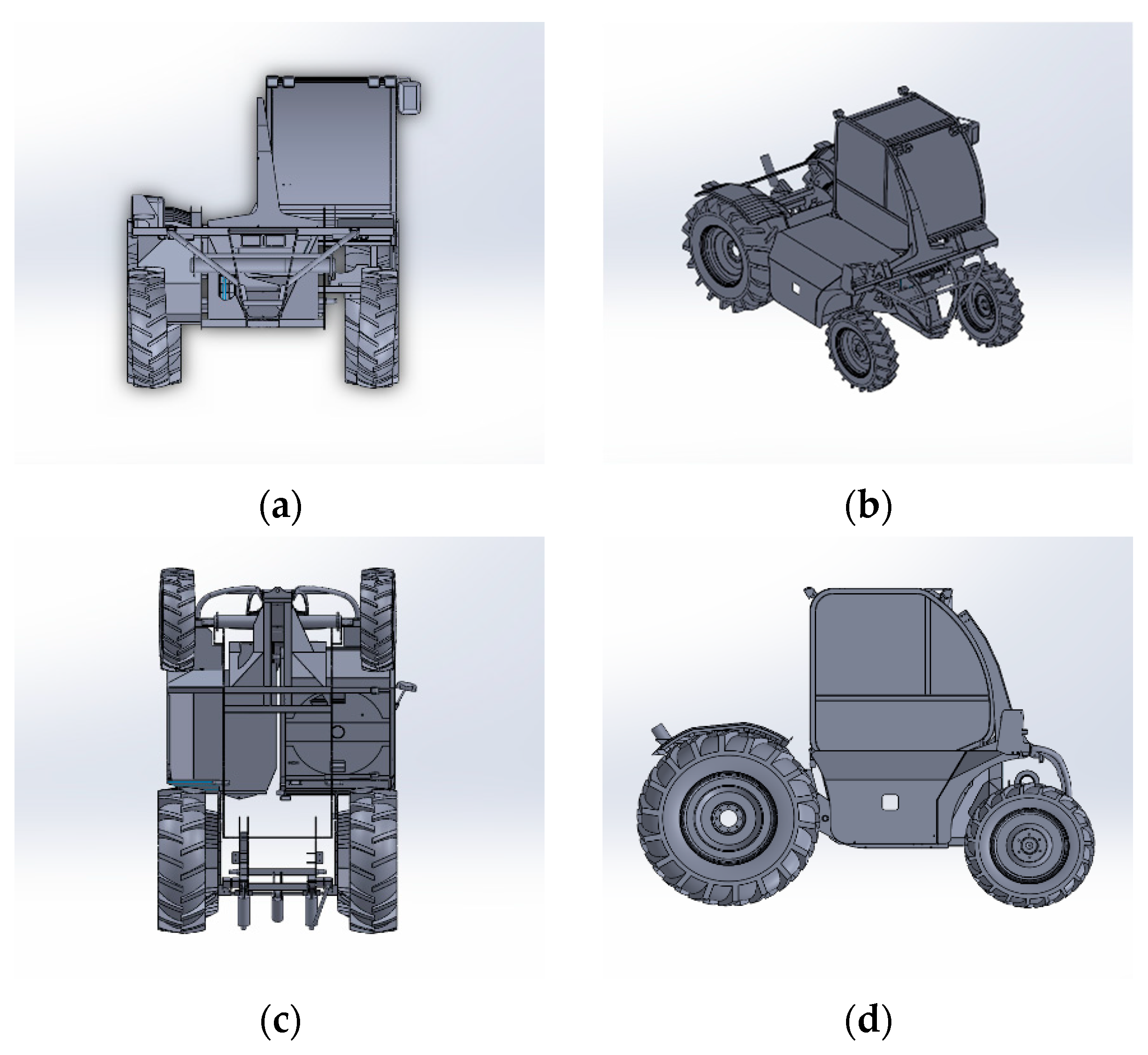
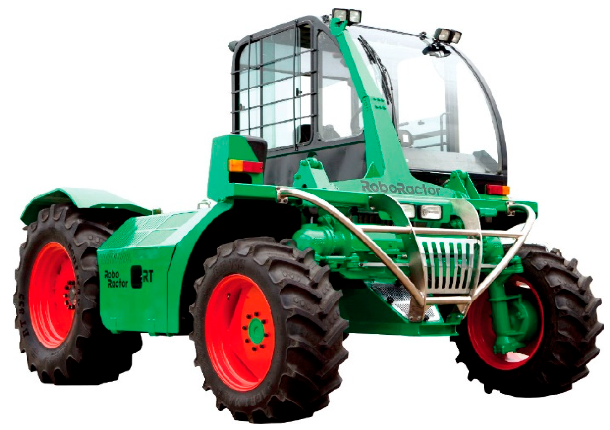
2.1. Tractor Used for Testing

The tractor utilized for testing is a model produced in South Korea and has a maximum traveling speed of 48.81 km/h. It comprises six main gears and two sub gears and is equipped with a high-power engine of over 90 kW, enabling it to perform various works in paddy and field. The performance tests for the minimum turning radius and static falling down sidelong angle were conducted at the Foundation of Agri. Tech. Commercialization and Transfer, Rep. Korea, which is an Organization for Economic Co-operation and Development (OECD) accredited testing institute for agricultural and forestry tractors. The static falling down sidelong angle and the minimum turning radius derived by the testing are 45.3° and 3.06 m, respectively. The shape and main specifications of the tractor used for testing are illustrated in Figure 1 and Table 1, and the performance tests are shown in Figure 2.

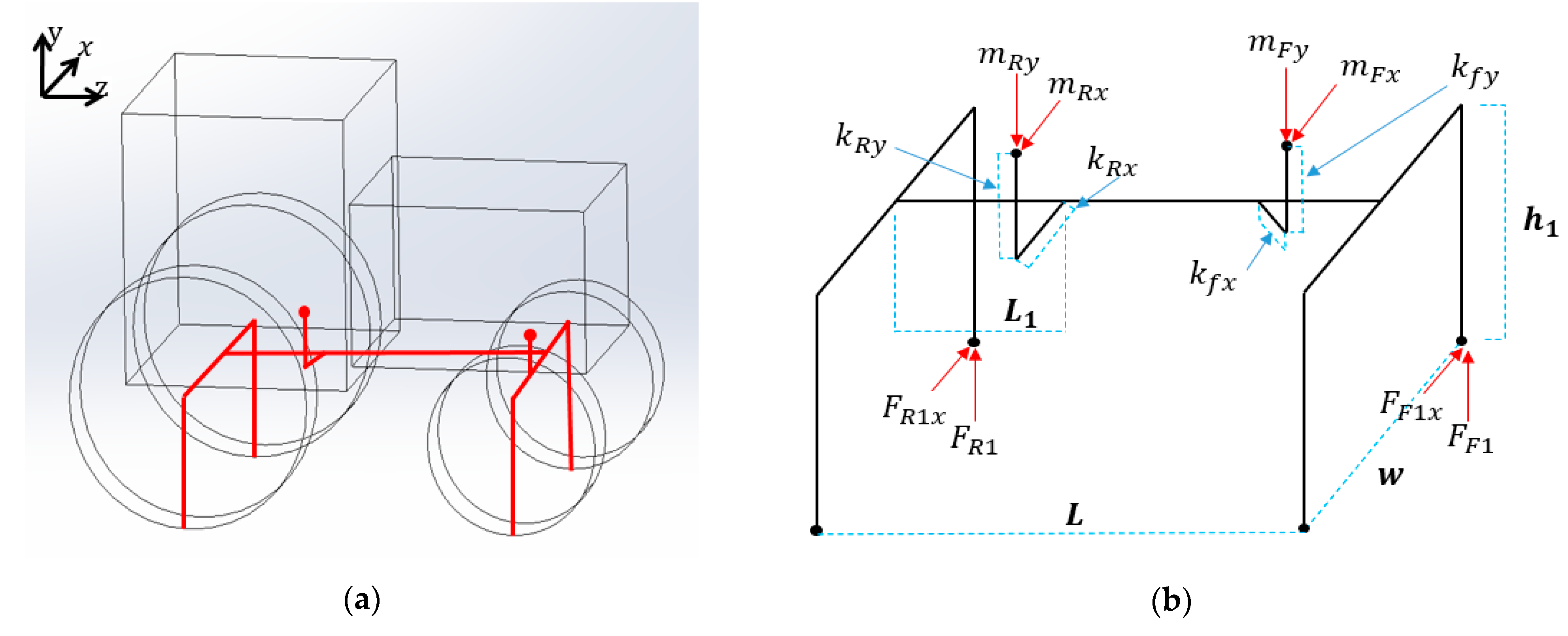
2.2. Theoretical Analysis of the Miniature Model’s Static Falling down Sidelong Angle

The lateral overturning of the tractor is analyzed theoretically by literature review, and the relationship between the original and miniature models is derived based on the analysis result. The main assumptions made to simplify the theoretical analysis are as follows:
-
The subject of the analysis is a four-wheel-drive tractor; hence, the weight of the front axle and front wheels cannot be ignored.
-
The slope angle increases quasi-statically (ignoring the dynamic effect), and the tire makes point contact with the ground.
-
The track widths of the front wheels and rear wheels are the same.
-
Slip does not occur between the tire and the ground, and the tire stiffness is ignored.
Figure 3a illustrates a simplified version of the tractor. In the static falling down sidelong angle experiment, the tractor is in a stationary state. Accordingly, the force exerted in the tractor’s moving direction ( z ) is zero. The free-body diagram of the tractor is illustrated in Figure 3b.
When the tractor is placed in the direction of the contour of the slope, the ground contact forces of the rear and front wheels located in the upper part of the slope are expressed by Equations (1) and (2), respectively [10].
F R 1 = m R g w L 1 L h 1 s i n θ w 2 c o s θ h 1 + k R y s i n θ + w 2 + k R x c o s θ
Here,
F R 1   = Rear upslope tire contact force
m R   = Mass of a component body of the tractor at rear (kg)
g = Gravitational acceleration (m/s2)
w = Track width (m)
L = Length of wheel base (m)
L 1   = Dimension from rear axle to rear center of gravity (m)
h 1   = Height of front-axle pivot (m)
θ = Slope angle
k R x = Downslope displacement of rear body center of gravity with respect to midplane (m)
k R y   = Height of rear body center of gravity above height of pivot (m)
F F 1 = m R g w L 1 L w 2 c o s θ h 1 s i n θ + m F g w [ w 2 + k F x c o s θ h 1 + k F y s i n θ
Here,
F F 1 = Front upslope tire contact force
m F = Mass of a component body of the tractor at front (kg)
k F x = Downslope displacement of front body center of gravity with respect to mid plane (m)
k F y = Height of front body center of gravity above the height of pivot (m)
When the inclination angle of the slope increases, either the front or rear wheel located in the upper part of the slope is lifted off the ground first, causing a Phase I rollover [8]. Afterward, the other wheel is lifted off the ground if the inclination angle continues to increase, and the tractor quickly overturns sideways. The moment the wheel begins to lift off the ground, the ground contact force of the wheel becomes zero.
If θ R 1   is the inclination angle at which the rear wheel starts to lift off the ground, it is the inclination angle when F R 1   is zero; hence, θ R 1   can be derived from Equation (1) as expressed below.
θ R 1 = t a n 1 w L L 1 2 k R x L 2 h 1 + k R y L h 1 L 1
Here,
θ R 1 = Instability angle when the upslope rear wheel is lifted
If the length, width, and height of the tractor are reduced by a similar ratio of 1 / n while maintaining the shape of the tractor, the variables included in Equation (3) are also reduced by a similar ratio of 1 / n . In the miniature model reduced to 1/n scale, the angle at which the rear wheel starts to lift off the ground is expressed by Equation (4). Here, w , L , and h 1   are variables related to the size of the tractor body, and L 1 , k R x , and k R y   are variables related to the position of the center of gravity. When the size of the tractor is reduced, the position of the center of gravity is also reduced by a similar ratio (1/n).
θ R 1 = t a n 1 1 n w 1 n L 1 n L 1 2 1 n k F x · 1 n L 2 1 n h 1 + 1 n k R y 1 n L 1 n h 1 · 1 n L 1
Here,
θ R 1 = Instability angle of the upslope rear wheel for the 1/n scale-down model
The following result can be obtained by eliminating the constant terms of 1/n2 in the denominator and numerator from Equation (4). Therefore, if the length, width, and height of the tractor are reduced by the same ratio while maintaining the overall shape of the tractor, the angle at which the rear wheel in the upper part of the slope starts to lift off the ground for the miniature model is equal to that of the original tractor.
θ R 1 = θ R 1  
In a similar manner, if θ F 1   is the inclination angle at which the front wheel starts to lift off the ground, it is the inclination angle when F F 1   is zero; hence, θ F 1   can be derived from Equation (2), as expressed below.
θ F 1 = t a n 1 m R w L 1 + m F w L 2 k F x L 2 m R h 1 L 1 + m F s h 1 + k F y
Here,
θ F 1 = Instability angle when the upslope front wheel is lifted
In Equation (6), m R and m F   are variables related to the weight of the tractor, and k F x  and k F y   are variables related to the position of the center of gravity. If the length, width, and height of the tractor are reduced by a similar ratio of 1/n while maintaining the materials and shape of the tractor, the weight is reduced by the ratio of 1/n3, whereas the position of the center of gravity is reduced by the ratio of 1/n. Therefore, the angle at which the front wheel starts to lift off the ground is expressed by Equation (7) for the miniature model reduced to 1/n scale.
θ F 1 = t a n 1 1 n 3 m R 1 n w 1 n L 1 + 1 n 3 m F 1 n w 1 n L 2 1 n k F x 1 n L 2 1 n 3 m R 1 n h 1 1 n L 1 + 1 n 3 m F 1 n s 1 n h 1 + 1 n k F y
Here,
θ F 1 = Instability angle of upslope front wheel for 1/n scale-down model
The following result can be obtained by eliminating the constant terms of 1/n5 in the denominator and numerator from Equation (7). Therefore, if the length, width, and height of the tractor are reduced by the same ratio while maintaining the materials and overall shape of the tractor, the angle at which the front wheel in the upper part of the slope starts to lift off the ground for the miniature model is equal to that of the original tractor.
θ F 1 = θ F 1  
Therefore, for the miniature model in which the length, width, and height are reduced by the same ratio while maintaining the materials and overall shape of the original tractor, the angle at which the front and rear wheels in the upper part of the slope starts to lift off the ground is equal to that of the original tractor. If both the front and rear wheels lift off the ground, lateral overturning occurs quickly; hence, the static falling down sidelong angles of the original tractor and the miniature model can be assumed to be the same.

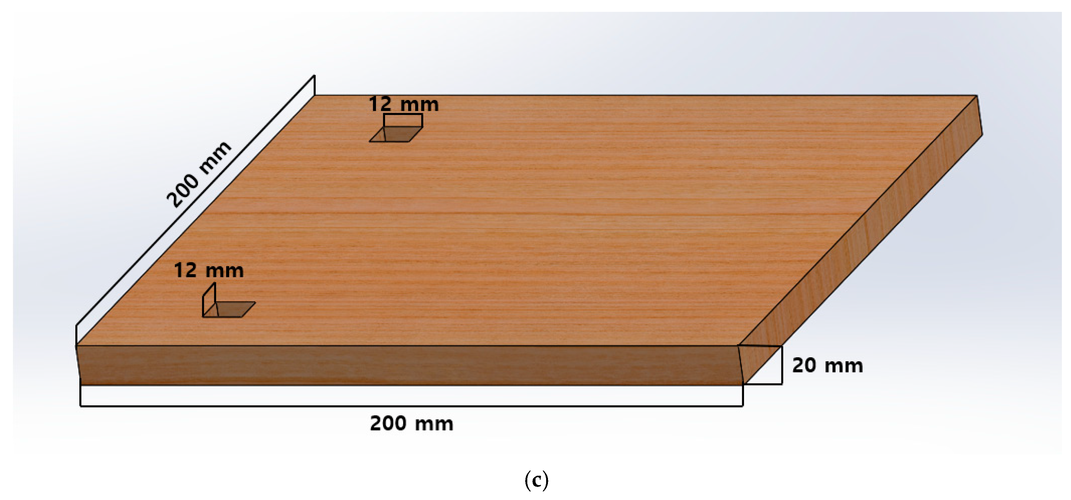
2.3. Miniature Model of the Tractor

2.3.1. Making of the Miniature Model Using a 3D Printer

A 3D model including the main body, front wheels, and rear wheels is produced by reflecting the actual dimensions and physical properties of the original tractor (Figure 4). In addition, the validity of the 3D model is verified by dynamic simulation of the static falling down sidelong angle and minimum turning radius [22].
The 3D model of the original tractor comprises various materials for each component; however, the miniature model is produced using a 3D printer and is made of a single material. Because the material composition is different, the position of the center of gravity and the weight of the front and rear parts do not become 1/n and 1/n3 of that of the original tractor, respectively, when the 3D model of the original tractor is reduced by 1/n and printed out with a 3D printer. Therefore, having made the physical properties of all components of the 3D model equal to the 3D printer material, the 3D model is partially modified so that the variables used in Equations (3) and (6) (track width, wheelbase width, the position of the center of gravity, front and rear axle weight, etc.) would be the same to the original model. The modification is performed by attaching a small additional structure to the lower part of the body such that it would not have much of an impact for the overall shape of the model. The final three-dimensional shape of the miniature model is completed by applying a reduction scale of 1/20 to the modified 3D model. Here, the relative position of the center of gravity with respect to the overall size is the same for both the original and miniature models (Figure 5).
The completed three-dimensional shape of the miniature model is applied to the 3D printer (Makerbot replicator+, Makerbot, Brooklyn, NY, USA) to manufacture the miniature model. The PLA plastic is utilized as the 3D printer material. The printer is FDM-type, and density was set to 10%. The material heat shrinkage was not considered, and no specific method was used to polish the surface after the model was printed. The shape and specifications of the manufactured miniature model are illustrated in Figure 6 and Table 2, respectively.

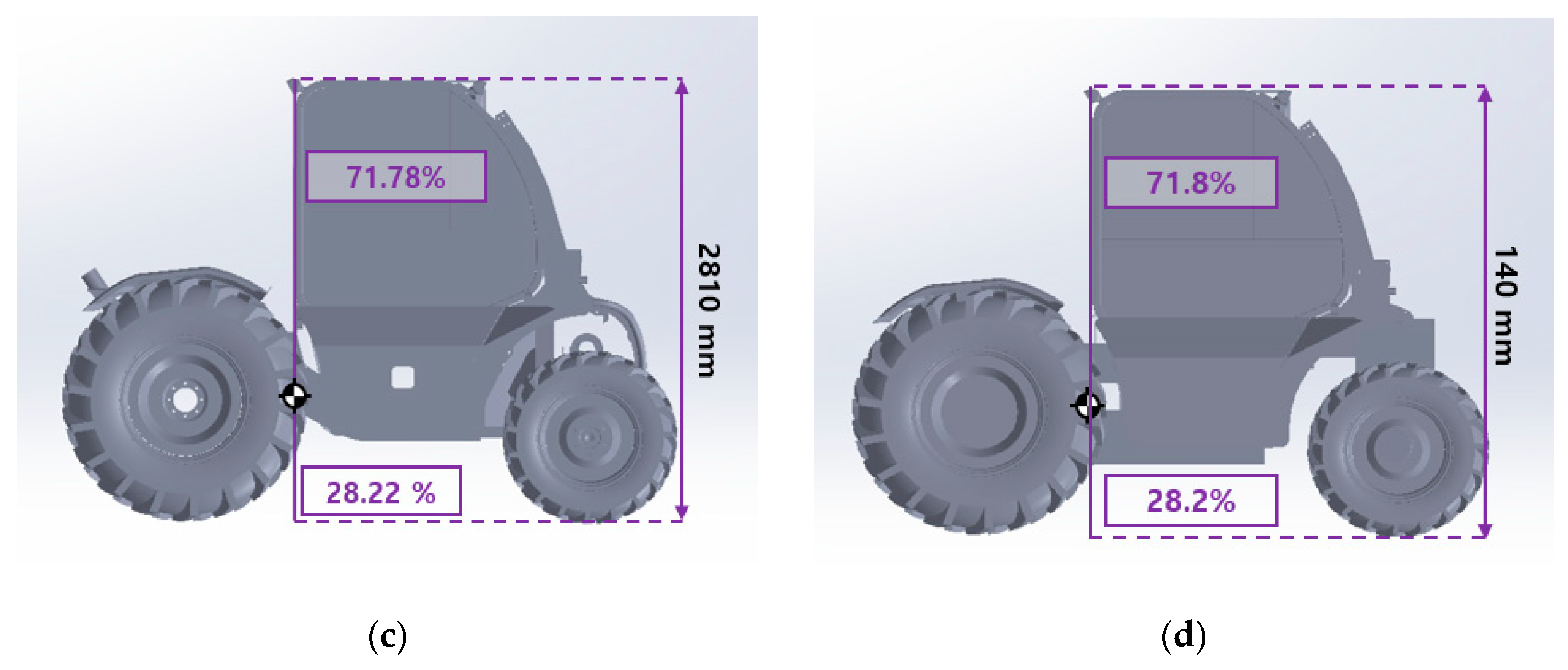
2.3.2. Verification of the Miniature Model

If the miniature model accurately reproduces the overall shape and relative position of the center of gravity of the tractor, the weight of the front and rear wheels should both be reduced by the same ratio (1/n3). Hence, the weight distribution ratio between the front and rear wheels should be the same to that of the original tractor.
The weight distribution ratios of the front and rear wheels of the original tractor, which is measured by the accredited certification test, are 45.9% and 54.1%, respectively. The front and rear wheels of the miniature model are weighed using an electronic scale, and the results are 129.8 g and 154.4 g, respectively. Accordingly, weight distribution ratios of the front and rear wheels of the miniature model are 45.7% and 54.3%, respectively (Figure 7). The difference between the weight distribution of the miniature model and the original tractor is 0.2%.; hence, it can be concluded that the miniature model used in this experiment has faithfully reproduced the original tractor [23]. Table 3 shows the results and difference of simulation and accredited certification test.

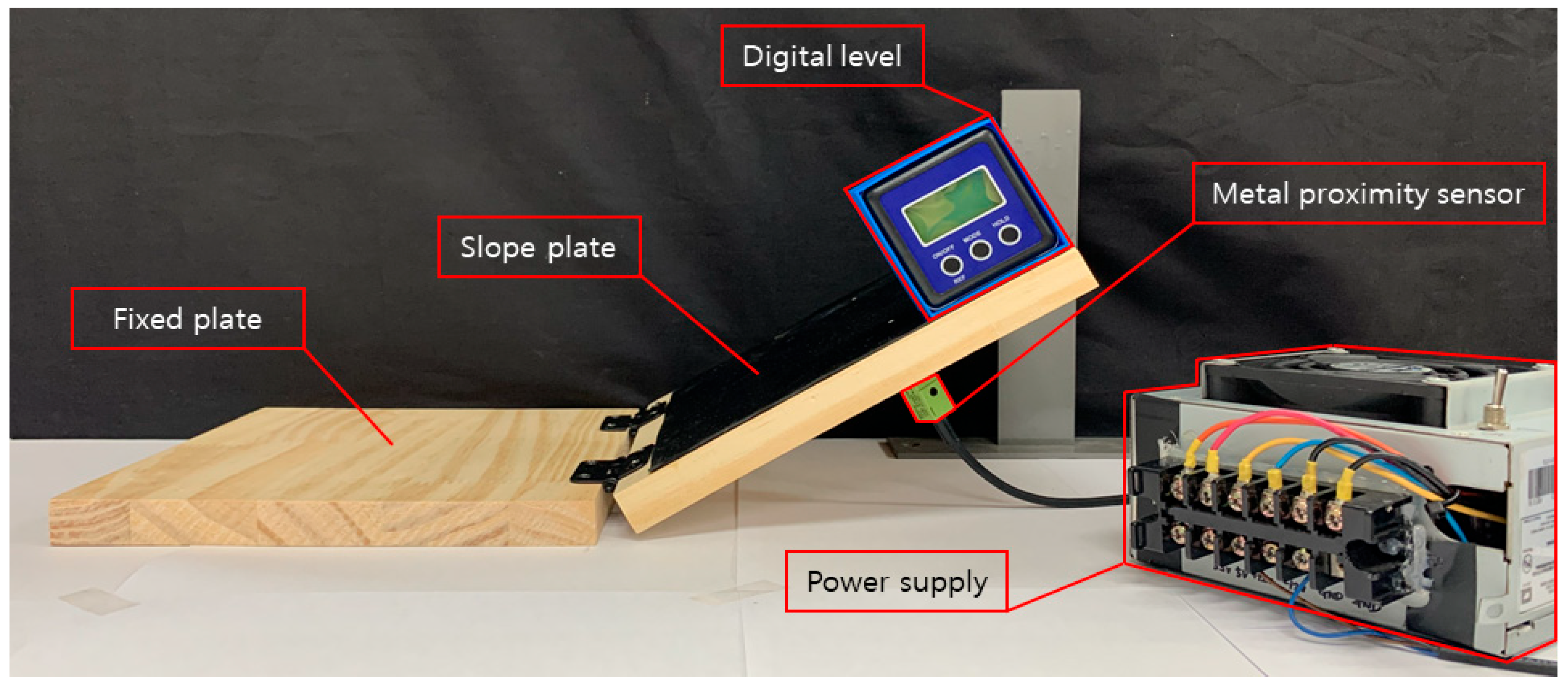
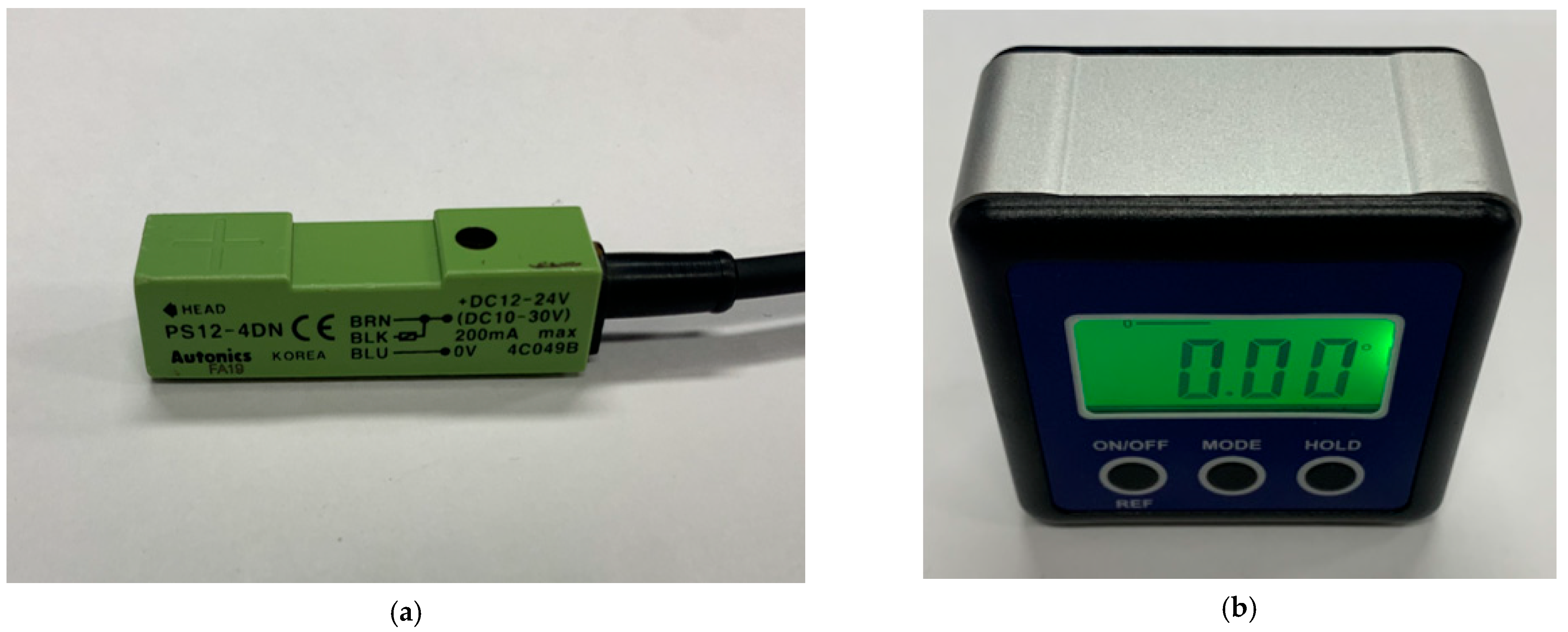
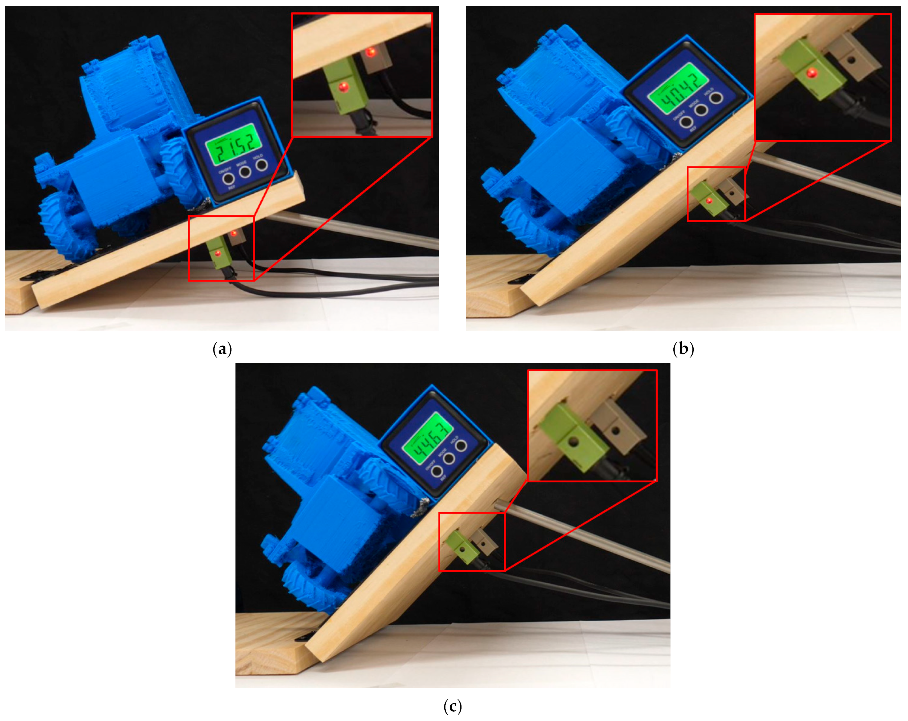
2.4. Test Platform Setup

A test platform was constructed to conduct the lateral overturning experiment of the miniature model. The platform comprises a fixed plate, which fixes the test device to the ground, a slope plate, which can adjust the inclination angle while the miniature model is on the slope, a digital level that can measure the inclination angle of the slope plate, a metal proximity sensor that can detect the distance between the tire and the ground, and a power supply device. Figure 8 illustrates the overall test platform.
The fixed and slope plates were made of wooden material in order not to affect the detection of the metal proximity sensor. These plates are connected by a hinge; hence, the inclination angle of the slope plate can be gradually increased. Considering the size of the miniature model, both the width and length of the fixed and slope plates are set to 200 mm. Two square holes with a length of 12 mm are made in the slope plate, centering on the points where the front and rear wheels of the miniature tractor located in the upper part of the slope plate are making contact, and the metal proximity sensor is inserted into these holes. Furthermore, a sideslip should not occur between the tire and the ground when measuring the static falling down sidelong angle of actual tractors. To prevent the sideslip, a 1-mm-thick synthetic rubber is attached on the slope plate. It has enough friction to prevent the sideslip of miniature model. An aluminum foil that can be detected by the proximity sensor, and for which the effect of its own weight can be ignored is attached to the bottom of the front and rear wheels of the miniature model. The proximity sensor is an on-off type; the red light is turned on when the proximity sensor is close to the aluminum foil of the front and rear wheels and is turned off when the proximity sensor is far from the aluminum foil. Accordingly, it is possible to identify the moment the front or rear wheel of the miniature model lifts off the slope plate when the inclination angle of the slope plate is gradually increased. The inclination angle is measured using the digital level. The shape and specifications of the components used to construct the test platform are illustrated in Figure 9 and Table 4 and Table 5.
The lateral overturning test of the miniature model using the test platform is conducted by gradually increasing the inclination angle of the slope plate and measuring the inclination angle at which the front and rear wheels of the miniature model located in the upper part of the slope lift off the sloping plate and finally lateral overturning occurred. This test is run five times, the inclination angle is measured each time, and the average value is used to analyze the static falling down sidelong angle.

3. Results and Discussion

Figure 10 illustrates the experimental procedure for checking the lateral overturning phenomenon when the inclination angle of the slope plate is gradually increased. As the inclination angle is increased, the proximity sensor is utilized to check whether the front and rear wheels are still making contact with the slope plate. Moreover, the angle at which the wheels start to lift off the slope plate is measured. As the inclination angle is increased, one of the two wheels located in the upper part of the slope plate first lifts off the plate. If the inclination angle is further increased, the remaining wheel lifts off the slope plate as well, and finally lateral overturning occurs rapidly.
Table 6 presents the results of the inclination angles at which the miniature model’s front and rear wheels in the upper part of the slope start to lift off the ground. The inclination angle of the rear wheel is small compared to the front wheel, which indicates that the rear wheel lifts off the ground before the front wheel. When both wheels in the upper part of the slope lift off the ground, lateral overturning occurs rapidly. hence, the inclination angle of the front wheel becomes the static falling down sidelong angle in this case. When measuring, the data could not be quantified through the sensor. The test was repeated 5 times to check the reproducibility and to obtain reliable average value.
The result of the miniature model test indicates an average static falling down sidelong angle of 44.3°. The standard deviation is 0.5° which is about 1.1% of the average value. Therefore, the test has high reproducibility.
Compared to the accredited certification test result of the original tractor which is 45.3°, the average miniature model test indicates a difference of 1.0%. Because the difference is small, and the time and cost required to run the test is relatively smaller than the certification test, it is concluded that a miniature model test can be utilized to derive the static falling down sidelong angle quickly and conveniently.

4. Conclusions

This paper presented a method for deriving a static falling down sidelong angle using a tractor miniature model and verified it through tests. We analyzed lateral overturning condition of tractors by literature review and derived a method to manufacture a miniature model based on the analysis result. A 1/20 scale miniature model was made using a 3D printer, and a test platform was constructed to perform a test for deriving the static falling down sidelong angle. As the inclination angle was increased, the angles at which the front and rear wheels of the miniature model started to lift off the ground were measured, and the static falling down sidelong angle was derived based on this result. The average static falling down sidelong angle derived from the miniature model test result and that of the original tractor obtained from the accredited certification test were 44.3° and 45.3°, respectively. Because both results indicate a difference of 1.0%, it was determined that the static falling down sidelong angle can be derived quickly and conveniently using a miniature model of tractor by applying the method utilized in this study. In the future, we are required to conduct a study that performs an in-depth verification of the method developed in this study by applying the method to a variety of agricultural machines.

Author Contributions

Theoretical and simulation analysis, S.-J.H., M.-K.J.; writing—original draft preparation, M.-K.J.; writing—review and editing, J.-S.N., C.-S.S. All authors have read and agreed to the published version of the manuscript.

Funding

This work was supported by Korea Institute of Planning and Evaluation for Technology in Food, Agriculture, Forestry (IPET) through Advanced Agricultural Machinery Industrialization Technology Development Program, funded by Ministry of Agriculture, Food and Rural Affairs(MAFRA)(321058-02).

Institutional Review Board Statement

Not applicable.

Informed Consent Statement

Not applicable.

Data Availability Statement

Data sharing not applicable.

Conflicts of Interest

The authors declare no conflict of interest.

References

  1. Jeong, B.Y.; Kim, Y.H. Ergonomic Guidelines and Intervention Procedures for Farm Workers. J. Ergon. Soc. Korea 2011, 30, 443–450. [Google Scholar] [CrossRef]
  2. Ali, M.; Lee, Y.S.; Kabir, M.S.N.; Kang, T.K.; Lee, S.H.; Chung, S.O. Kinematic analysis for design of the transportation part of a tractor-mounted Chinese cabbage collector. J. Biosyst. Eng. 2019, 44, 226–235. [Google Scholar] [CrossRef]
  3. Hyun, D.Y. Computer Simulation of Sideways Overturning of Agricultural Tractors. Ph.D. Thesis, Seoul National University, Suwon, Korea, 1987. [Google Scholar]
  4. Rural Development Administration. 2012 Agricultural Machinery Safety Accident. 2013. Available online: http://www.nongsaro.go.kr/portal/ps/psb/psbk/kidofcomdtyDtl.ps?menuId=PS00067&kidofcomdtyNo=28785 (accessed on 7 November 2017). (In Korean)
  5. Rondelli, V.; Casazza, C.; Martelli, R. Tractor rollover fatalities, analyzing accident scenario. J. Saf. Res. 2018, 67, 99–106. [Google Scholar] [CrossRef] [PubMed]
  6. Ministry of Agriculture, Forestry and Fisheries. Outline of Fatal Accidents during Farm Work in 2015. 2017. Available online: http://www.maff.go.jp/j/seisan/sien/sizai/s_kikaika/anzen/pdf/sibou24.pdf (accessed on 21 May 2017). (In Japanese)
  7. Abubakar, M.S.; Ahmad, D.; Akande, F.B. A review of farm tractor overturning accidents and safety. Pertanika J. Sci. Technol. 2010, 18, 377–385. [Google Scholar]
  8. Kim, K.U.; Hong, J.P. Modeling Static Stability of Agricultural Tractor. In Proceedings of the Korean Society for Agricultural Machinery Conference, Seoul, Korea, 19–22 October 1993; pp. 1127–1136. [Google Scholar]
  9. Guzzomi, A.L. A revised kineto-static model for Phase I tractor rollover. Biosyst. Eng. 2012, 113, 65–75. [Google Scholar] [CrossRef]
  10. Baker, V.; Guzzomi, A.L. A model and comparison of 4-wheel-drive fixed-chassis tractor rollover during Phase I. Biosyst. Eng. 2013, 116, 179–189. [Google Scholar] [CrossRef]
  11. Li, Z.; Mitsuoka, M.; Inoue, E.; Okayasu, T.; Hirai, Y.; Zhu, Z. Prediction of tractor sideslipping behavior using a quasi-static model. J. Fac. Agric. Kyushu Univ. 2015, 60, 215–218. [Google Scholar] [CrossRef]
  12. Kim, Y.Y.; Noh, J.S.; Shin, S.Y.; Kim, B.I.; Hong, S.J. Improved method for determining the height of center of gravity of agricultural tractors. J. Biosyst. Eng. 2016, 41, 170–176. [Google Scholar] [CrossRef]
  13. Kang, N.R.; Choi, I.S.; Lee, W.J.; Woo, J.K.; Kim, Y.K.; Choi, Y.; Hyun, C.S.; Yoo, S.N. Sideways overturning and overturning angle test for a three-wheel riding-type cultivator. J. Biosyst. Eng. 2019, 44, 12–17. [Google Scholar] [CrossRef]
  14. Bietresato, M.; Mazzetto, F. Stability tests of agricultural and operating machines by means of an installation composed by a rotating platform (the “turntable”) with four weighting quadrants. Appl. Sci. 2020, 10, 3786. [Google Scholar] [CrossRef]
  15. Park, W.K.; Kim, K.U.; Kim, J.W.; Song, T.Y.; Park, M.S.; Cho, K.H. Sideways overturning analysis of forwarder using a multibody dynamics analysis program. J. Biosyst. Eng. 2002, 27, 185–194. [Google Scholar] [CrossRef]
  16. Demšar, I.; Bernik, R.; Duhovnik, J. A mathematical model and numerical simulation of the static stability of a tractor. Agric. Conspec. Sci. 2012, 77, 143–150. [Google Scholar]
  17. Choi, K.H.; Kim, S.M.; Hong, S.H. Analysis of static stability by modified mathematical model for asymmetric tractor-harvester system: Changes in lateral overturning angle by movement of center of gravity coordinates. J. Biosyst. Eng. 2017, 42, 127–135. [Google Scholar] [CrossRef]
  18. Lysych, M.N. A study of the static lateral stability of a tillage machine-tractor unit on a virtual stand. J. Phys. Conf. Ser. 2020, 1515, 042033. [Google Scholar] [CrossRef]
  19. Lysych, M.N. Study driving dynamics of the machine-tractor unit on a virtual stand with obstacles. J. Phys. Conf. Ser. 2020, 1515, 042079. [Google Scholar] [CrossRef]
  20. Carson, J.S. Introduction to modeling and simulation. In Proceedings of the 2005 Winter Simulation Conference, Orlando, FL, USA, 4 December 2005; p. 8. [Google Scholar] [CrossRef]
  21. Calle, M.A.; Salmi, M.; Mazzariol, L.M.; Kujala, P. Miniature reproduction of raking tests on marine structure: Similarity technique and experiment. Eng. Struct. 2020, 212, 110527. [Google Scholar] [CrossRef] [Green Version]
  22. Hwang, S.J.; Jang, M.K.; Nam, J.S. Application of lateral overturning and backward rollover analysis in a multi-purpose agricultural machine developed in south korea. Agronomy 2021, 11, 297. [Google Scholar] [CrossRef]
  23. Ahn, Y.S.; Baek, W.K. Thrust simulation and experiments for underwater thrusters. J. Korean Soc. Power Syst. Eng. 2017, 21, 51–59. [Google Scholar] [CrossRef]
Figure 1. Picture of the tractor used.
Applsci 12 00043 g001
Figure 2. Pictures of the performance tests: (a) Minimum turning radius test; (b) Static falling down sidelong angle test.
Applsci 12 00043 g002
Figure 3. Tractor model for theoretical analysis: (a) Simplification of the general tractor model; (b) Free body diagram.
Applsci 12 00043 g003
Figure 4. 3D model of the tractor used: (a) Front view; (b) Isometric view; (c) Bottom view; (d) Side view.
Applsci 12 00043 g004
Figure 5. Overall dimension and relative position of the gravity center for the original and 1/20 scale-down miniature model: (a) Length and width ratio of the original model; (b) Length and width ratio of the miniature model; (c) Height ratio of the original model; (d) Height ratio of the miniature model.
Applsci 12 00043 g005aApplsci 12 00043 g005b
Figure 6. Measurement of axle weight of the miniature tractor: (a) Front axle; (b) Rear axle.
Applsci 12 00043 g006
Figure 7. Measurement of axle weight of the miniature tractor: (a) Front axle; (b) Rear axle.
Applsci 12 00043 g007
Figure 8. View of the test platform.
Applsci 12 00043 g008
Figure 9. Shapes of products used in the test platform: (a) metal proximity sensor; (b) digital level; (c) slope plate.
Applsci 12 00043 g009aApplsci 12 00043 g009b
Figure 10. Lateral overturning test using the developed miniature model and test platform: (a) Contact of both wheels; (b) Falling off of the rear wheel and contact of the front wheel; (c) Falling of both wheels (then lateral overturning occurred rapidly).
Applsci 12 00043 g010
Table 1. Specifications of the tractor used.
ItemsSpecification
ModelRT135
Manufacturer, NationDaeHo, Korea
Length/Width/Height (mm)4080/2345/2810
Weight (N)46,300
EngineRated power (kW)/Speed (rpm)95.6/2250
Minimum ground clearance (mm)374
Traveling speedMinimum (km/h)1.86
Maximum (km/h)48.81
Minimum turning radius (mm)3.06
Static falling down sidelong angle (°)45.3
Table 2. Specifications of the miniature tractor.
Overall Dimensions (Length/Width/Height (mm))Weight (g)
204/117/140280.5
Table 3. Comparison of weight distribution between the original and reduced model.
Original Model (%)Miniature Model (%)Difference (%)
Front wheels45.945.70.2
Rear wheels54.154.3
Table 4. Specifications of the metal proximity sensor.
ItemsSpecification
ModelPS12-4DN
Manufacturer, NationAUTONICS, Korea
Measuring range (mm)4
Standard detector (mm)12 × 12 × 1 (Metal)
AccuracyWithin 10% of detection distance
Table 5. Specifications of the digital level.
ItemsSpecification
ModelAdvanced digital level
Manufacturer, NationYATO, Korea
Measuring range (°)360
Resolution (°)0.01
Accuracy (°)±0.1
Precision (°)±0.1
Table 6. Instability angle for upslope front and rear wheels.
Test No.Instability Angle (°)
Upslope Front WheelUpslope Rear Wheel
145.041.0
244.140.7
344.141.9
444.640.4
543.839.9
Avg. ± Std.44.3 ± 0.540.8 ± 0.7
Publisher’s Note: MDPI stays neutral with regard to jurisdictional claims in published maps and institutional affiliations.

