Article

Protection Scheme for a Wavelength-Division-Multiplexed Passive Optical Network Based on Reconfigurable Optical Amplifiers

Department of Electrical and Computer Engineering, Tamkang University, 151 Yingzhuan Road, Tamsui District, New Taipei City 251301, Taiwan
*
Author to whom correspondence should be addressed.
Appl. Sci. 2022, 12(1), 365; https://doi.org/10.3390/app12010365
Submission received: 27 November 2021 / Revised: 27 December 2021 / Accepted: 28 December 2021 / Published: 31 December 2021

Abstract

:
This paper demonstrates a wavelength-division-multiplexed passive optical network (WDM-PON) scheme based on novel reconfigurable optical amplifiers (ROAs). The measured switching characteristics of the ROA3 constructed with a 2 × 2 crossbar optical switch and a four-port reversible optical circulator (OC) and a conventional EDFA can meet the requirements of most network management and surveillance. The self-made four-port reversible OC’s response time is less than 2 ms, and its insertion losses are about 1 dB or less for all the transmission paths and switching states. An optimal design of ROAs is proposed and evaluated for bidirectional optical amplifier protection, in which ROA3 has an EDF length of 7.5 m long with a 1480 nm pump laser and possesses a backward or forward pumping configuration with the corresponding pump power of 200 mW or 50 mW. We verified the scheme’s feasibility through a simulation of WDM-PON systems with 40 downstream and upstream channels. This scheme enables the intelligent protection switching in practical operation scenarios for high-capacity multi-wavelength networks.

1. Introduction

The wavelength-division-multiplexed passive optical network (WDM-PON) will play a promising role in future broadband access solutions, owing to its wide bandwidth, high security, easy upgradeability, and network flexibility [1,2,3]. The low-cost WDM-PON schemes using tunable lasers have become practical for deployment in the access and transport networks and are considered in the standardization process [4,5]. These schemes can provide the needed bandwidth and performance for future mobile networks as well as reach extension and service provisioning for thousands of users. Due to the extended transmission distance and large power splitting, optical amplifiers are crucial for the network planning and deployment needs.
There are three basic types of optical amplifiers that may be used at different positions of an optical network. A post-amplifier placed immediately after optical transmitters can be used to boost the signal level to extend reach. It features high input power, medium optical gain, and high output power. The noise figure (NF) of a booster amplifier is not usually a critical parameter [6,7,8]. At the receiving end of an optical link, a pre-amplifier may be required to amplify the weak optical signal before a photodetector in order to improve the signal-to-noise ratio (SNR). A large gain with low NF is needed [6,7]. To compensate for the transmission loss of a link of long distance or large number of power splitting, in-line amplifiers are placed within an optical link. An in-line amplifier typically requires a moderate gain, a low NF, and a high output power [6,7]. Because of its high gain, high power, low NF, and insensitivity to polarization of the signal, the erbium-doped fiber amplifier (EDFA) has become the most popular optical amplifier and a necessary component in optical fiber communication systems [9].
The protection scheme for optical networks is vital to assure network reliability and service quality. This is even a critical issue in the access networks connecting mobile networks and data centers due to the drastically increasing traffic in the links. Moreover, the present WDM-PON architecture is expected to play an important role in the infrastructure of optical millimeter-wave (MMW) data access and 5G/B5G mobile fronthaul and backhaul links [10,11]. Table 1 shows the failure rates and repair times for some network components [12,13]. Because of its high failure rate and poor reliability, the EDFA fails easily, possibly causing a great loss of the optical signal that passes through it. Therefore, a protection scheme for optical amplifiers is a vitally important topic. The protection for optical amplifiers in WDM-PONs is extremely important since an EDFA can serve tens or even hundreds of wavelength channels.
To date, most of the protection schemes for WDM-PONs have stressed the protection of working feeder fibers or distribution fibers [14,15,16,17]. Nevertheless, in [13], the proposed optimal protection architecture for WDM-PONs based on various design rules can protect the fixed transceivers, the EDFA in an optical line terminal (OLT), and the trunk between the OLT and remote node (RN). However, this protection architecture does not meet the protection requirement of the uplink EDFA.
To provide a consummate protection for EDFA, we propose a protection scheme for WDM-PONs with reconfigurable optical amplifiers (ROA) whereby the working EDFAs on both downlink and uplink paths can be protected. In our scheme, the ROAs are implemented in the OLT to enable switching in different protection scenarios. The detailed operation principles and the implementation of ROAs are discussed in Section 3 and Section 4, respectively. The feasibility of the scheme is verified by simulations with 10 Gb/s downstream and upstream transmissions in Section 5.

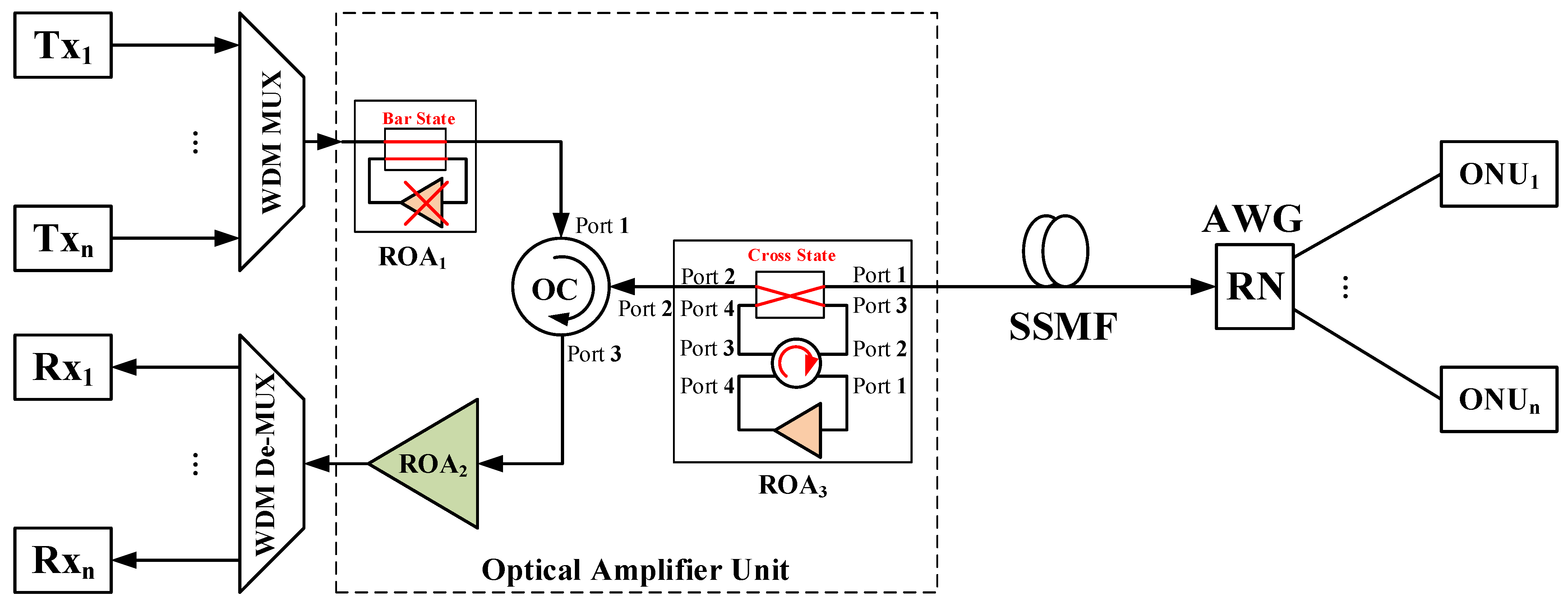
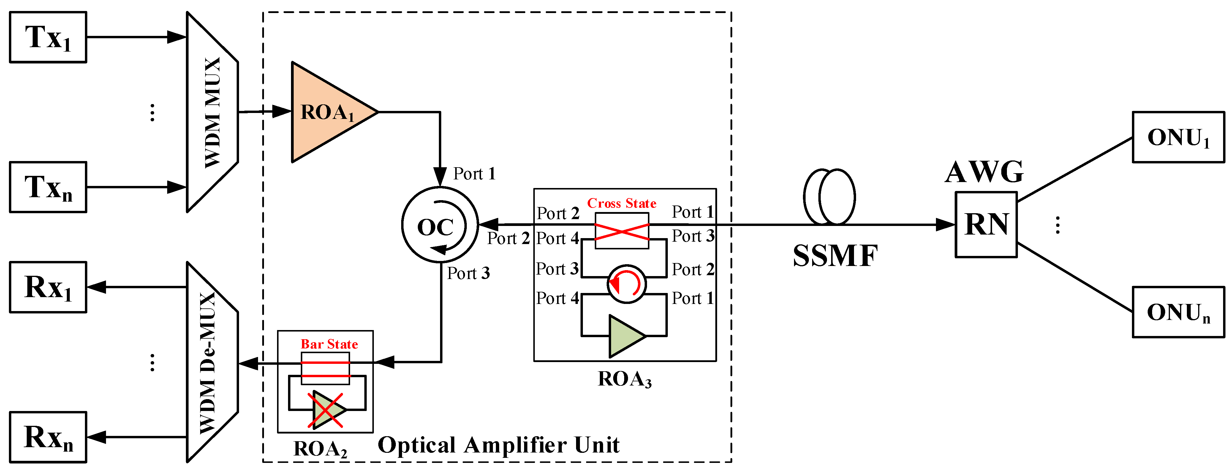
2. Proposed Protection Scheme for WDM-PONs

The proposed protection scheme for WDM-PONs based on ROAs is shown in Figure 1. In the proposed scheme, the optical amplifier unit includes three types of ROAs: ROA1, ROA2, and ROA3. ROA1 is a type of post-amplifier on the downstream path and ROA2 is a type of pre-amplifier on the upstream path. ROA3 enables switching between the post-amplifier and pre-amplifier so that it can be used as a backup optical amplifier for either ROA1 or ROA2.
Tx1–Txn and Rx1–Rxn in the OLT are transmitters and receivers, respectively. All downstream signals are multiplexed by a WDM multiplexer (MUX) at the OLT. The multiplexed signal is amplified by ROA1 and then transmitted through port 1 to port 2 of an optical circulator (OC). The output signal from port 2 of the OC is launched into the bypass path of the 2 × 2 crossbar optical switch in ROA3 and then fed to a standard single-mode fiber (SSMF) that is connected to a 1 × N arrayed-waveguide grating (AWG) at the remote node (RN). After being de-multiplexed at the RN, each downstream signal is connected to the corresponding optical network unit (ONU). All upstream signals from ONU1 to ONUn are multiplexed by the AWG at the RN. The multiplexed signal is launched into the SSMF and then fed to the bypass path of ROA3. The bypass signal is transmitted through port 2 to port 3 of the OC and amplified by ROA2. After being de-multiplexed by a WDM de-multiplexer (De-MUX), each upstream signal is connected to the corresponding Rx.
In general, EDFA pumping schemes can be categorized into three arrangements, namely, forward-pumped (co-pumped), backward-pumped (counter-pumped), and bidirectional-pumped (dual-pumped) configurations [18]. The main advantage of a forward-pumped EDFA is low NF and that of a backward-pumped EDFA is high output power. Therefore, in the proposed protection scheme, ROA1 adopts a backward-pumped configuration to gain high output power, whereas ROA2 uses a forward-pumped configuration to acquire low NF. Moreover, ROA3 is implemented such that it can switch between the backward-pumped and forward-pumped EDFA so that it can be used as a backup optical amplifier for ROA1 or ROA2.

3. Operation Principles and Reconfigurable Optical Amplifier Scheme

As shown in Figure 2a, ROA1 consists of an EDFA (post-amplifier) and one 2 × 2 crossbar optical switch (OS). The 2 × 2 crossbar OS should be in the cross state most of the time. When the EDFA in ROA1 fails, the OS turns into the bar state such that the signal bypasses the failed EDFA.
Figure 2b shows the block diagram of ROA2, which comprises an EDFA (pre-amplifier) and a 2 × 2 crossbar OS. Similar to ROA1, the OS in ROA2 should be in the cross state most times, and when the EDFA in ROA2 fails, it turns into the bar state for the signal to bypass the failed EDFA.
As shown in Figure 2c, ROA3 is composed of a bidirectional EDFA, a four-port reversible OC [19], and a 2 × 2 crossbar OS. By using the reversible OC, ROA3 can easily change the direction of the signal, thereby achieving various pumping configurations but no change in the direction of the pumping source. Remarkably, the four-port reversible circulator in ROA3 is a non-strict-sense circulator, so the signal from port 1 to port 4 or port 4 to port 1 is unavailable. Furthermore, the 2 × 2 crossbar OS and the EDFA in ROA3 are generally in the bar state and the off state, respectively; hence, ROA3 cannot be used to amplify the signal.
Figure 3 shows the protection state for ROA1, the downstream optical amplifier in the WDM-PON. When ROA1 fails, the built-in 2 × 2 crossbar OS switches to the bar state, consequently allowing the signal to bypass the EDFA in ROA1. Simultaneously, ROA3 switches its own function to that of ROA1; hence, its built-in 2 × 2 crossbar OS switches to the cross state and the direction of the four-port reversible OC becomes clockwise.
Figure 4 shows the protection state for ROA2, the upstream optical amplifier in the WDM-PON. When ROA2 fails, the built-in 2 × 2 crossbar OS switches to the bar state, consequently allowing the signal to bypass the EDFA in ROA2. Simultaneously, ROA3 switches its own function to that of ROA2; hence, its built-in 2 × 2 crossbar OS switches to the cross state and the direction of the four-port reversible OC becomes counterclockwise.
The design of ROA3 is the key in the proposed protection scheme and is addressed in the next section.

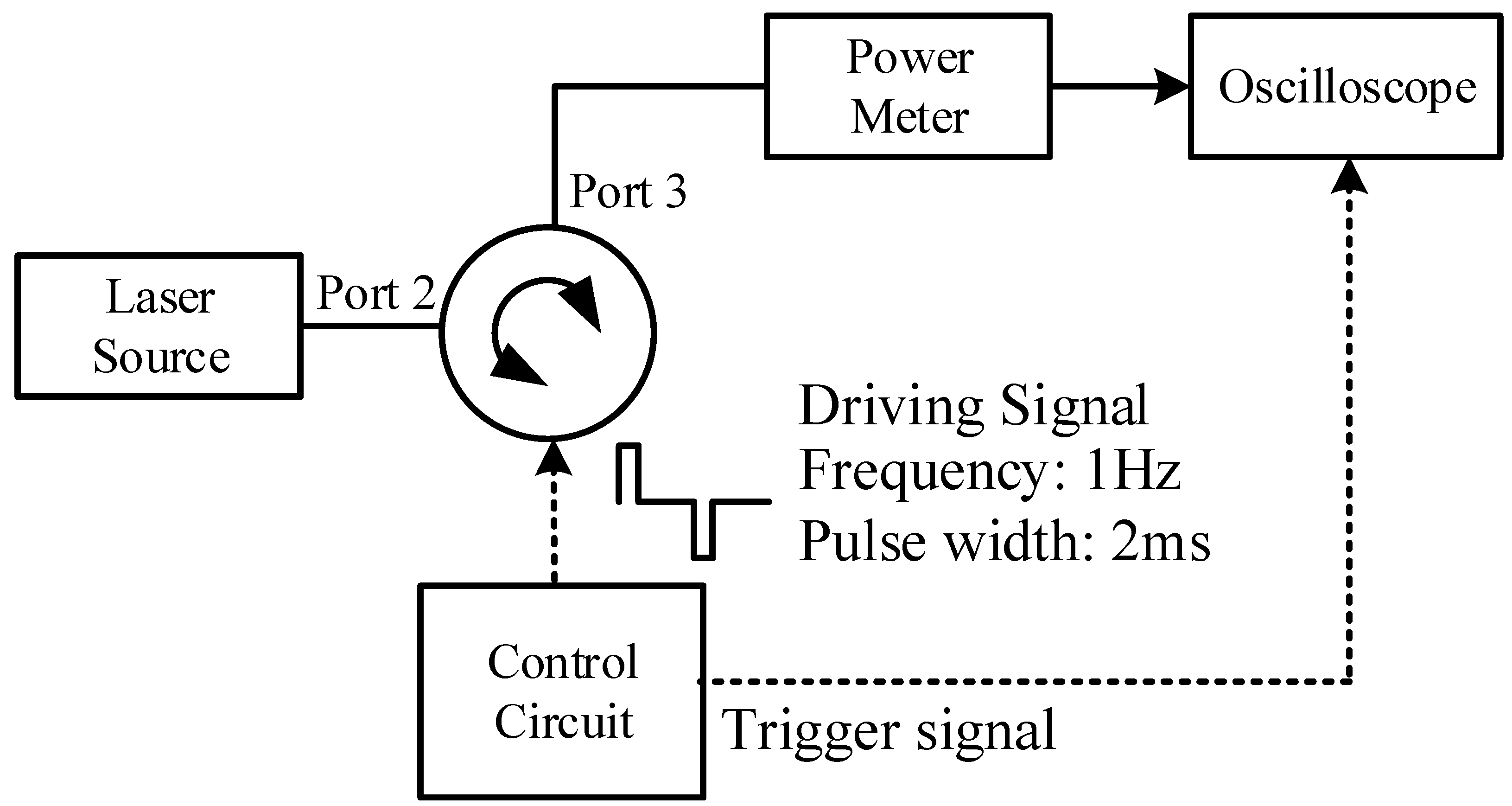
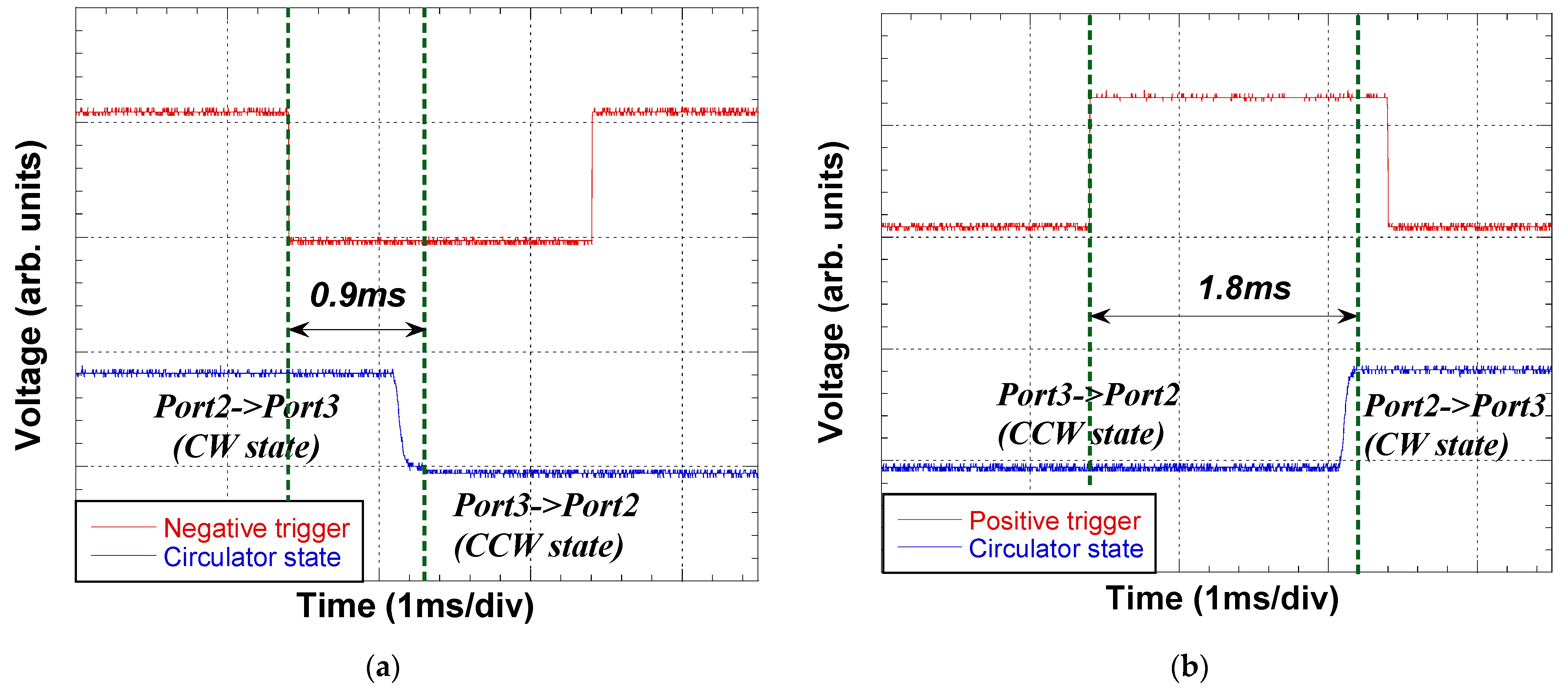
4. Implementation of ROA3

The ROA3 comprises a bidirectional EDFA, a four-port reversible OC, and a 2 × 2 crossbar OS. The OS is commercially available, whereas the bidirectional EDFA and four-port reversible OC must be specifically designed and produced. The ROA3 is designed and optimized by using simulation software, VPItransmissionMakerTM Ver. 8.5 (VPI 8.5). We then verify the performance of the self-made four-port reversible OC experimentally.

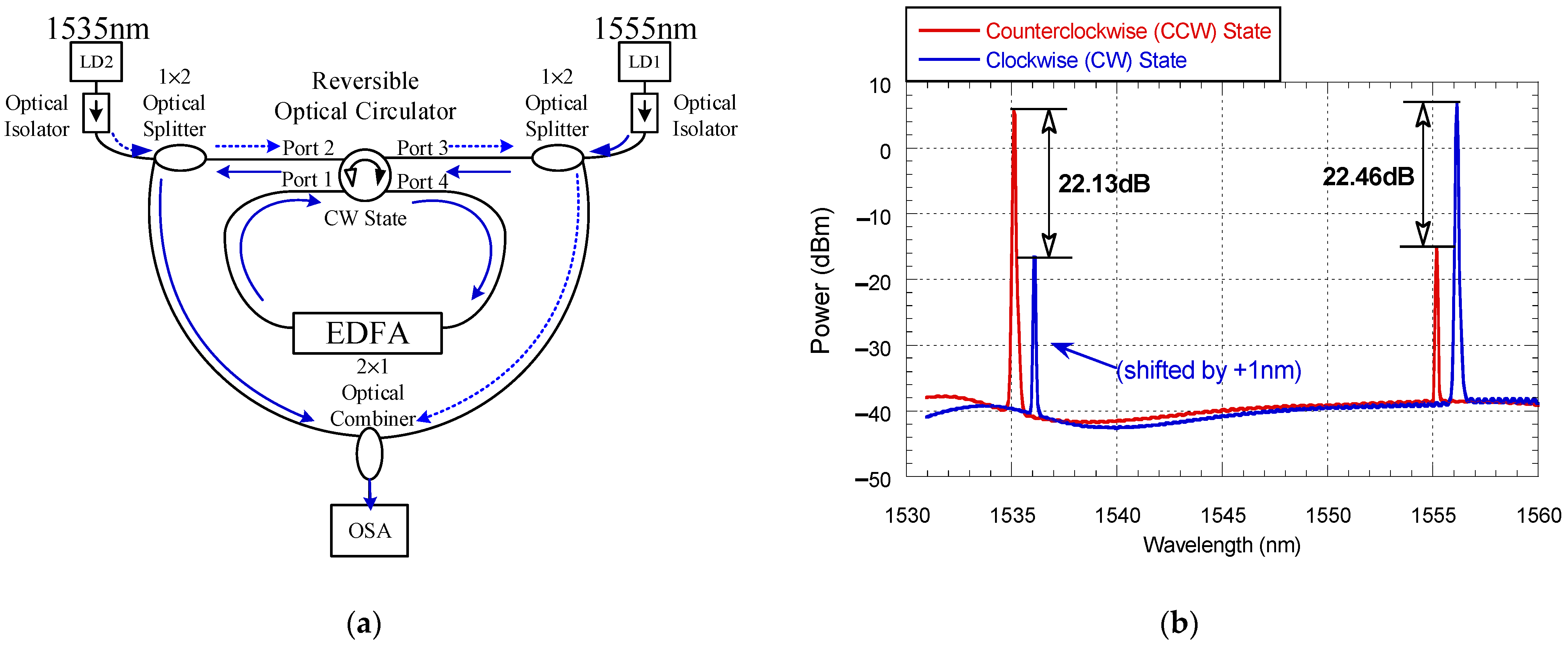
4.1. Characteristics of Key Components in ROA3

The measured insertion loss (IL) for the 2 × 2 crossbar OS and the self-made four-port reversible OC of ROA3 is summarized in Table 2. The IL is about 1 dB or less for all the transmission paths and switching states of the two key components. The commercial 2 × 2 crossbar OS has a response time of <10 ms.
Figure 5 shows the measurement setup for the response time of the four-port reversible OC. The optical circulator is controlled by a control circuit. The measured response time can be observed from Figure 6 to be 0.9 ms when the OC switches from the clockwise direction, while it is 1.8 ms for the reverse switching. The upper curves are triggered signals generated by the control circuit, while the lower curves are the output waveforms from port 3. The response time of the four-port reversible OC can meet the requirement of most network management and surveillance.
The four-port reversible OC is combined with the customized bidirectional EDFA to create a reversible optical amplifier. Its dynamic switching function is characterized by inputting light sources of two different wavelengths into port 2 and port 3, as shown in Figure 7a. The power of both input light sources is −7 dBm. Figure 7b shows the dynamic function measurement results, wherein the gain obtained by the clockwise amplification is 22.46 dB for the LD1 lightwave, and that obtained by the counterclockwise amplification is 22.13 dB for the LD2 lightwave. It can be clearly seen that when the light source in one of the directions is subjected to amplification, the light source in the other direction will be bypassed.

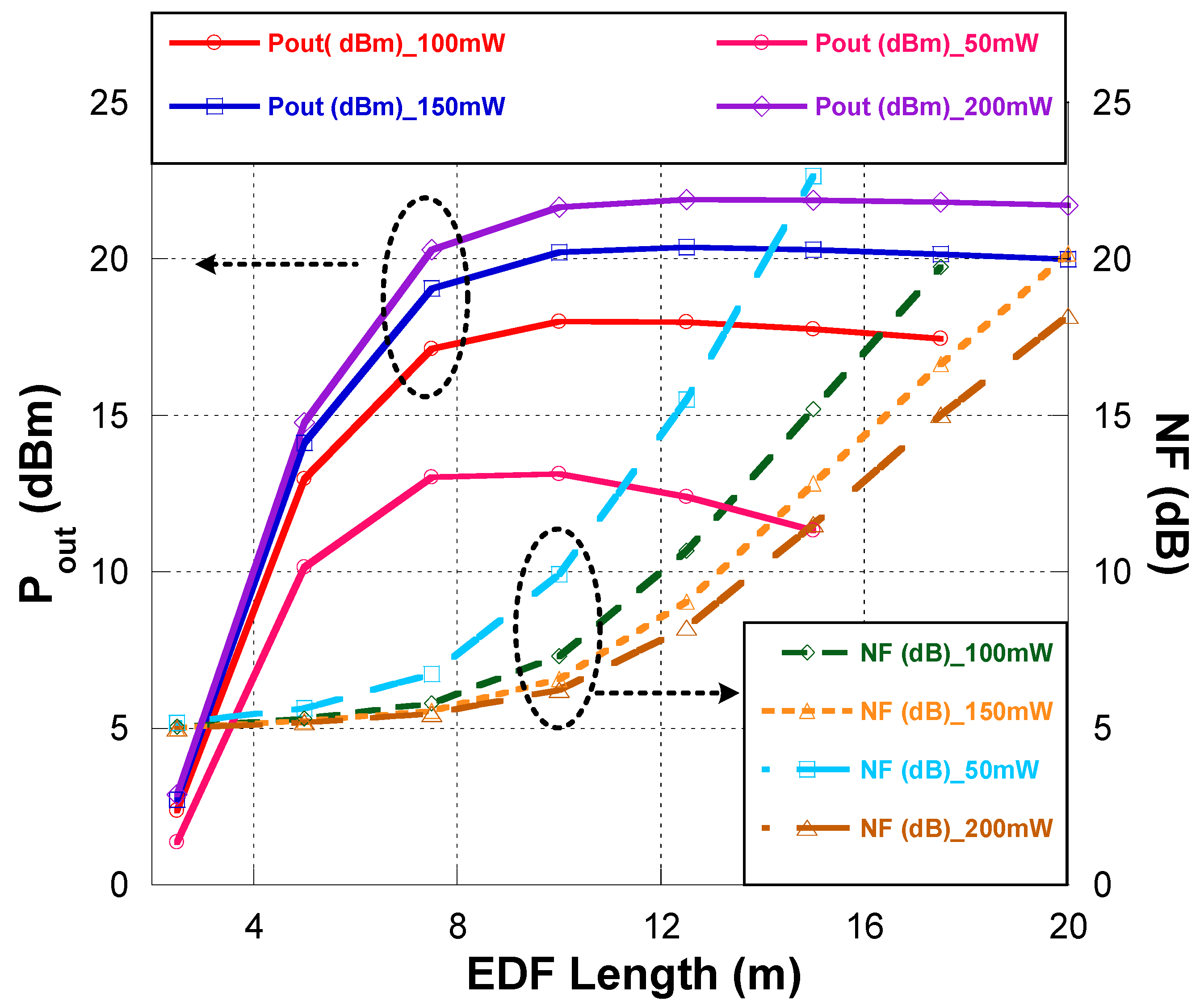
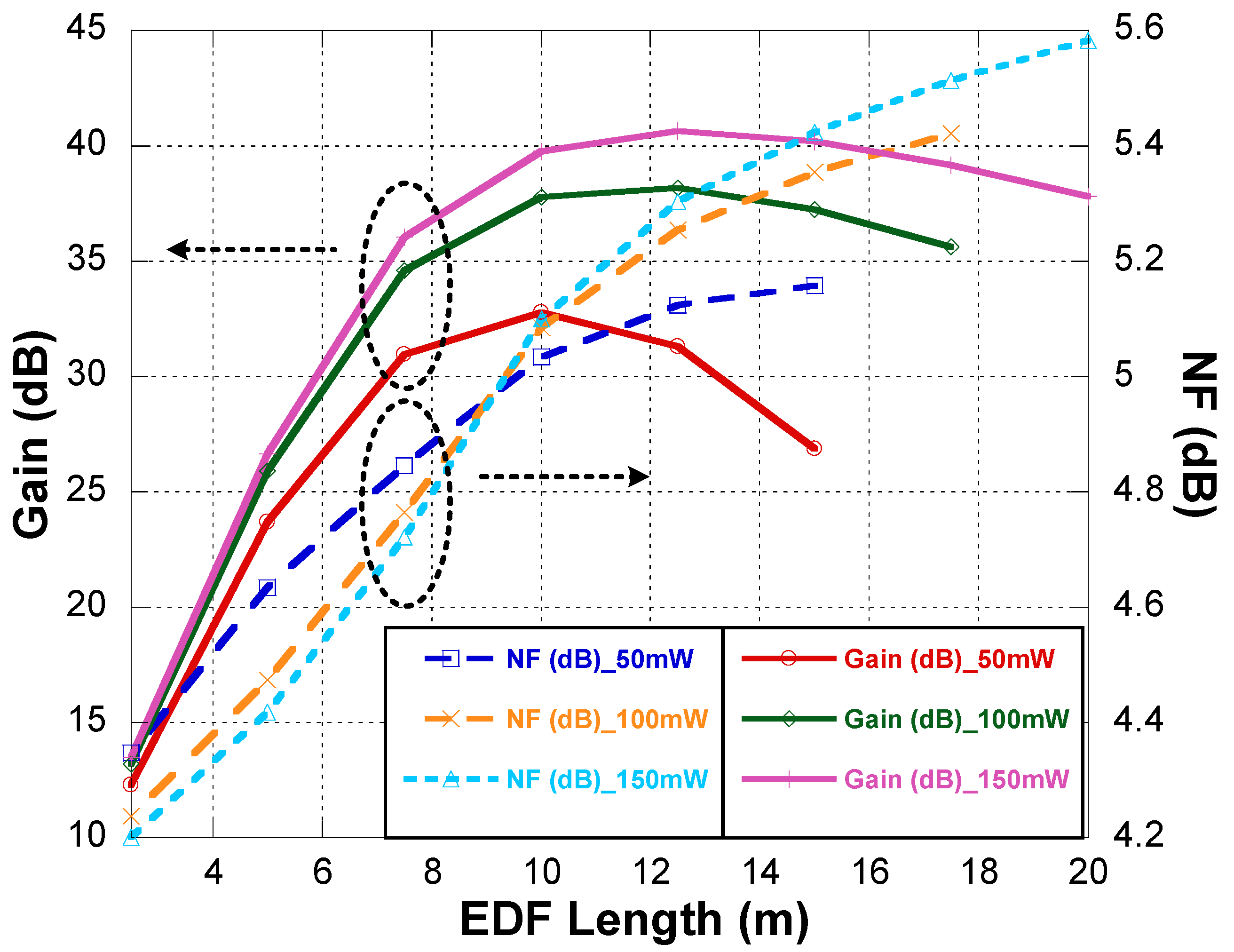
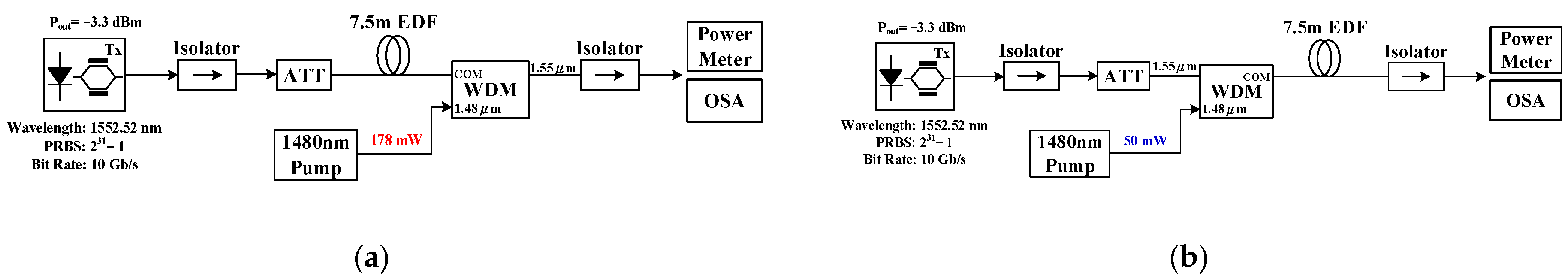
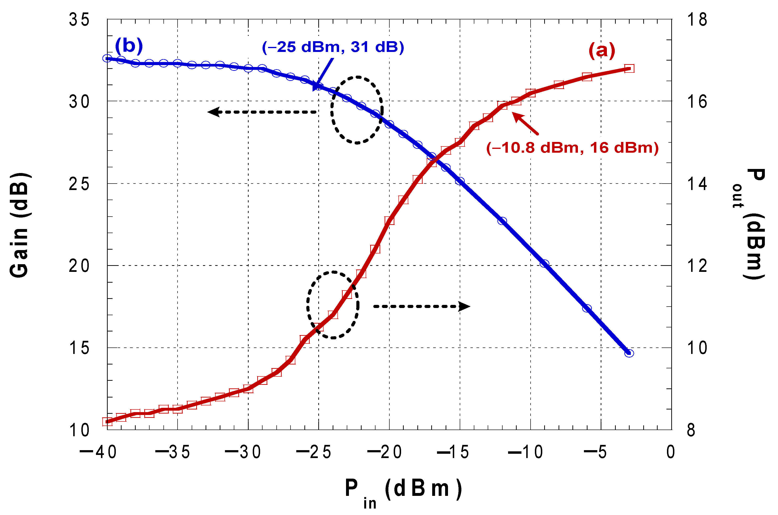
4.2. Optimum Design of the Bidirectional EDFA

The EDFA in ROA3 consists of an erbium-doped fiber (EDF), a 1480 nm pump laser, and a passive wavelength coupler. ROA3 has the EDFA, a 2 × 2 crossbar OS, and the four-port reversible OC that provides two equivalent reversible optical isolators. Since the direction of the signal might change in different scenarios, two optical isolators are not required in the EDFA. Furthermore, the EDFA in ROA3 uses only one pump laser; thus, it is cost effective.
During the simulation, we model the EDFA using a built-in rate equation in VPI 8.5 in order to realize the optimum design of the bidirectional EDFA in ROA3. Many simulations on the performance analysis of an EDFA have been reported [18,20,21], based on which we determine the main parameters for the simulation. The parameters are shown in Table 3.

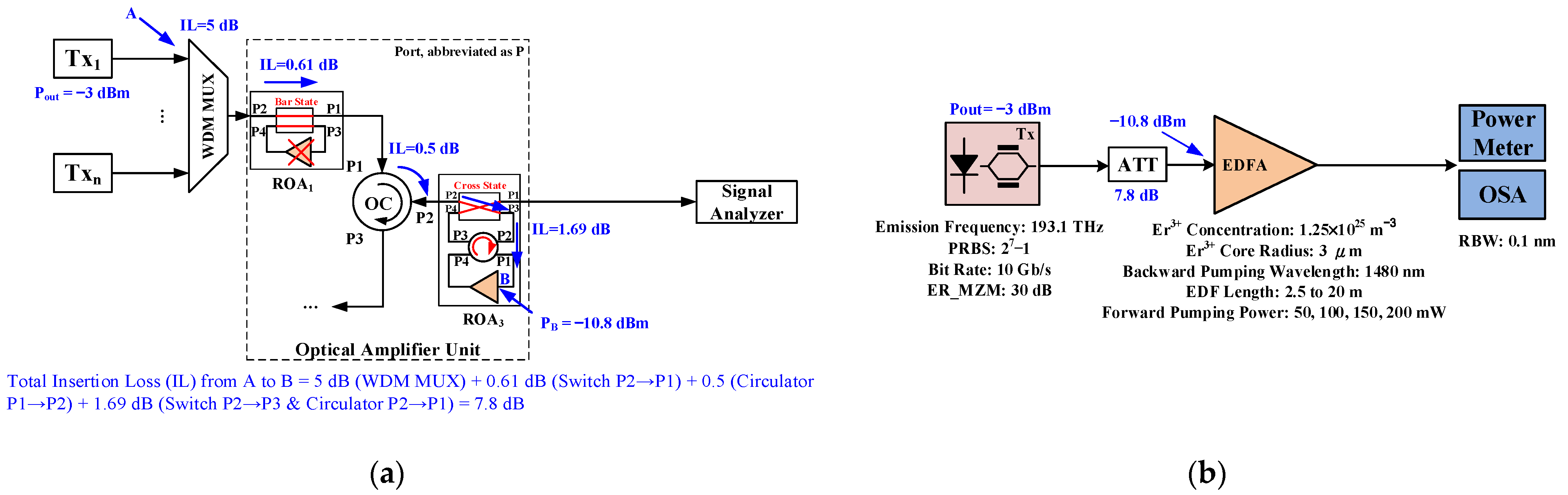
4.2.1. Backup Optical Amplifier for ROA1

For ROA3 to serve as a backup optical amplifier for ROA1, its pumping configuration should be backward pumping in order to provide the function of a high output power similar to that of a post-amplifier (post-amp).
In the simulation setup, shown in Figure 8, a single-channel signal is amplified by an EDFA, which is then analyzed by a signal analyzer. The single-channel signal is generated by a transmitter that comprises a continuous wave (CW) light from a laser diode at 193.1 THz, which is modulated via a Mach-Zehnder modulator (MZM). The parameters of the transmitter are shown in Figure 8b. Before launching into the EDFA, the signal from the transmitter will suffer some IL due to passive components. As shown in Figure 8a, the total IL from A to B is 7.8 dB; hence, the input optical power of the EDFA is −10.8 dBm.
The NF and the output power (Pout) of the backward-pumping EDFA vary along with the EDF length at different pumping powers of 50, 100, 150, and 200 mW, as shown in Figure 9. To achieve the output power requirement of 20 dBm, the EDF length and pumping power must be greater than 7.5 m and 150 mW, respectively. It is found that the NF decreases gradually as the pumping power increases. This trend is similar to the simulation result in [20].

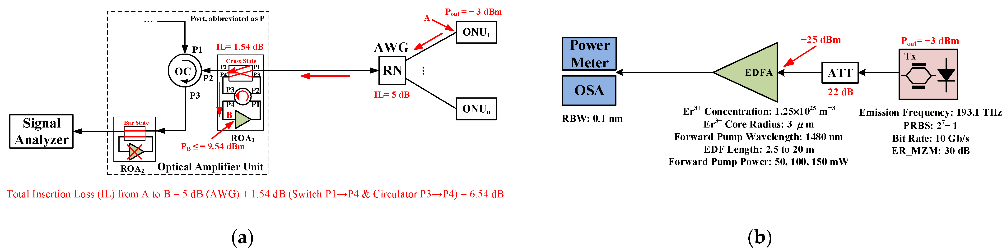
4.2.2. Backup Optical Amplifier for ROA2

For ROA3 to serve as a backup optical amplifier for ROA2, its pumping configuration must be forward pumping in order to provide the function of high gain and low NF, similar to those of a pre-amplifier (pre-amp).
The simulation setup is shown in Figure 10. From Figure 10a, the total IL from A to B is 6.54 dB; hence, the input optical power of the EDFA is −9.54 dBm. Because the minimum input optical power of commercial C-band EDFA pre-amplifiers ranges from −25 to −30 dBm per channel [8], the input optical power of the EDFA can be reduced to −25 dBm by an attenuator.
The NF and the gain of the forward-pumping EDFA vary with the EDF length at different pumping powers of 50, 100, and 150 mW, as shown in Figure 11. To achieve the gain requirement of 30 dB, the EDF length and pumping power must be greater than 7.5 m and 50 mW, respectively. Furthermore, the NF decreases as the pumping power increases when the EDF length is less than 9 m. For an EDF length greater than 9 m, NF increases as the pumping power increases.
Table 4 lists the parameters of the EDFA in ROA3 for the simulation results. For the EDFA having a backward- or forward-pumping configuration, the pumping power is 200 mW or 50 mW, respectively. In a practical application, the pump power can be adjusted by the driving current of the pump laser for achieving energy efficiency.
The simulated EDFA performance is experimentally verified by assembling an EDFA by a commercial highly doped EDF, a pump laser, a wavelength multiplexer, and an optical isolator into a forward- or backward-pumping configuration. The experimental setup is shown in Figure 12 for backward- and forward-pumping configurations. A 10 Gb/s MZM transmitter is used as the signal source with an output optical power of −3.3 dBm. The pumping source is a 1480 nm pump laser, and a 7.5 m EDF is used as the gain medium. Since the maximum output current of the laser controller is limited at 1 A, the output power of the pump laser can only reach 178 mW.
The output optical power curve under different input optical powers in the backward-pumping configuration, Figure 13a (curve) shows that an output optical power of 16 dBm can be obtained when the input power is −10.8 dBm. If the pump laser can output 200 mW of pumping power the output power is expected to reach 20 dBm. Figure 13b (curve) shows the gain curve under different input optical powers in the forward-pumping configuration. When the input power is −25 dBm, the gain can reach 31 dB, which is in line with the simulation results, and the NF value is less than 4 dB.

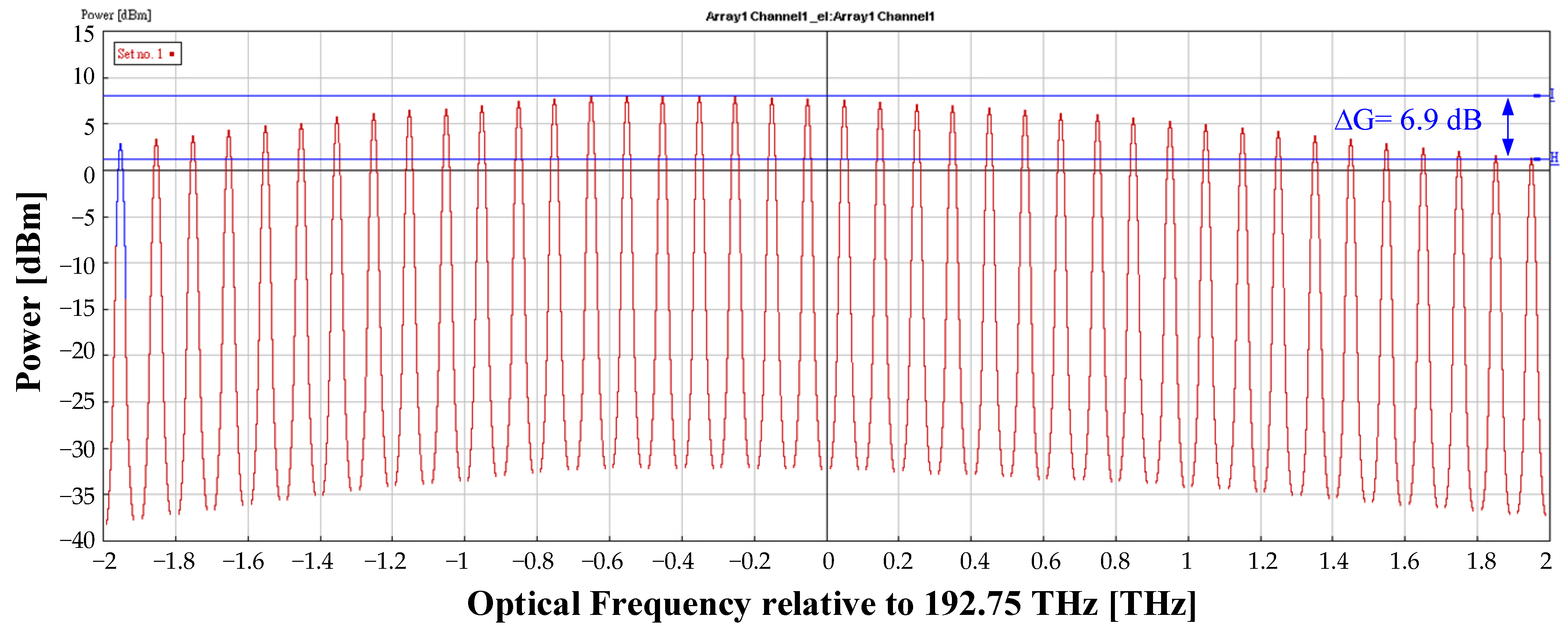
5. Simulation of a 40-Channel WDM-PON

In this section, the simulation by using VPI 8.5 for a 40-channel 10 Gb/s WDM-PON system containing the proposed ROAs is investigated for the protection states shown in Figure 3 and Figure 4.

5.1. Protection Scheme for ROA1

The simulation setup and parameters for the protection state where ROA3 is used to backup ROA1 are similar to those shown in Figure 8 with additional SSMF, AWG at the RN, and ONUs. Based on the results in Section 5, the EDFA the in ROA3 has 7.5 m long EDF and 200 mW pumping power. In the simulation scenario, the 40-channel signals bypass the failed EDFA in ROA1 and are amplified by ROA3. The amplified signal is then transmitted via the SSMF and de-multiplexed by a 1 × 40 AWG (De-MUX) at the RN to distribute to the ONUs for bit error rate (BER) analysis. Each transmitter consists of a CW laser diode and an MZM, and the optical power of each channel is −3 dBm. The output optical power of the EDFA is 22.05 dBm. Furthermore, the receiver mainly consists of a PIN-TIA photodetector and a Bessel filter, and the received optical signal is analyzed using a BER analyzer.
Figure 14 shows the output optical spectrum after ROA3. The gain flatness (∆G) is 6.9 dB because ROA3 does not contain any gain flattening filter (GFF). The gain difference may be acceptable for the single-stage amplification since the crosstalk effect between adjacent channels is negligible in our simulation. A GFF can be added to improve gain flatness if needed.
The BER curves of CH1 (190.8 THz, 1571.24 nm), CH20 (192.7 THz, 1555.75 nm), and CH40 (194.7 THz, 1539.77 nm) are shown in Figure 15, Figure 16 and Figure 17, respectively. For a BER of 10−9, the difference in the Rx sensitivities of these three channels is not obvious on a back-to-back (B2B) condition; the Rx sensitivity is approximately −22.8 dBm. After transmitting via the SSMF, fiber dispersion has the most significant effect on CH1; the longest transmitted distance of CH1 is limited to 85 km, whereas that of the remaining two channels is up to 95 km. Moreover, fiber dispersion has the lowest influence on CH40, with it having lower the minimum required received optical power (ROP) of approximately −20.08 dBm for a BER of 10−9.

5.2. Protection Scheme for ROA2

The simulation setup and parameters for the protection state where ROA3 is used to backup ROA2 are similar to those shown in Figure 10 with additional SSMF between RN and the optical amplifier unit. The de-multiplexer and optical receivers are also included to characterize the system performance. Based on Section 5 results, the EDFA in ROA3 has a 7.5 m long EDF and 50 mW pumping power. In the simulation scenario, the 40-channel signals are amplified by ROA3 and bypass the failed EDFA in ROA2. The upstream data rate is 10 Gb/s, the same as the downstream signals. The transmitted optical power of each channel is −3 dBm.
Figure 18 shows the output optical spectrum after the optical amplifier unit. The gain difference ∆G is 7.36 dB, which can be improved by adding a GFF. The BER curves of CH1, CH20, and CH40 are shown in Figure 19, Figure 20 and Figure 21, respectively. Because of the pre-amplification, these channels’ Rx sensitivities are remarkable in the B2B condition for a BER of 10−9. CH20 has the highest gain, and so the greatest Rx sensitivity of −38.65 dBm. After the signal transmission by the SMF, fiber dispersion has the most significant effect on CH1; the longest transmitted distance of CH1 is 80 km, whereas fiber dispersion has the least influence on CH40, resulting in the longest transmitted distance of up to 100 km. The minimum required ROP for a BER of 10−9 at CH1, CH20, and CH40 are −26.52 dBm, −32 dBm, and −33 dBm, respectively, after signal transmission via the 80 km SMF.
To verify our protection scheme’s performance for ROA1 and ROA2 in the full band (CH1 to CH40), we adopted the same channels to demonstrate and analyze upstream and downstream unidirectional transmission, separately. Noticeably, the Rayleigh scattering and reflection issues of the same wavelength band used for both downstream and upstream can significantly degrade the signals’ quality. We can mitigate this degradation by splitting the full band into two sub-bands or the odd and even channel groups, one for each direction.

5.3. System Margin for ROA3

The proposed WDM-PON system margin is dominated by the state where ROA3 is functioning as an optical amplifier to backup either ROA1 or ROA2 since ROA3 has an additional IL from the reversible OC. Therefore, the system margin for downstream is calculated by considering the path loss from the output port of the optical amplifier in ROA3 to the ONU (see Figure 3). After ROA3 amplifies the signal, the three channels’ powers are 2.96 dBm, 7.708 dBm, and 1.335 dBm, respectively. Their powers are attenuated by the total link loss of 16.54 dB, resulting in their received powers of −13.58 dBm, −8.832 dBm, and −15.205 dBm, respectively. The minimum required ROPs for a BER of 10−9 at CH1, CH20, and CH40 are −21.92 dBm, −22.06 dBm, and −22.19 dBm, respectively. The detailed system margins for a transmission distance of 50 km of the protection scheme for ROA1 are listed in Table 5. Under the minimum system margin of 6.985 dB, the CH40 longest transmission distance is equal to 50 km.
The system margin analysis for upstream transmission over 50 km SSMF is summarized in Table 6 for the protection state where ROA2 fails, as shown in Figure 4. The three channels’ powers are all −3 dBm, which are attenuated by the total link loss of 16.54 dB, resulting in their received powers of −19.54 dBm. The minimum required ROPs for a BER of 10−9 at CH1, CH20, and CH40 are −31.817 dBm, −35.91 dBm, and −35.09 dBm, respectively, then the three channels’ corresponding system margins for the upstream signals are all greater than 12 dB, benefiting from the high gain of ROA3.

6. Conclusions

This paper presented a novel protection scheme for working EDFAs on both downstream and upstream paths. A backup optical amplifier based on a reconfigurable optical amplifier was implemented in the optical line terminal to enable intelligent protection switching in practical operation scenarios. Our scheme has three main advantages. (1) The proposed amplifier has the function of switching between the post-amplifier and pre-amplifier to serve as a backup optical amplifier for the working EDFA on the downstream or upstream path. (2) The response time of the proposed amplifier is lower than 10 ms; therefore, it can meet the requirement of most network management and surveillance. (3) The backup optical amplifier was optimized using simulation software; furthermore, it can achieve the output power and gain requirement of 20 dBm and 30 dB via the same EDF. The proposed scheme can realize in a cost-effective and energy-efficient manner. In addition, the feasibility of the scheme was verified through a simulation using 40-channel 10 Gb/s downstream and upstream WDM-PON transmission systems. In the simulation results, the optimized EDFA in ROA3, whose length of EDF is 7.5 m long with a 1480 nm pump laser, has a backward- or forward-pumping configuration with the corresponding pump power of 200 mW or 50 mW to achieve the system margin of about 7 dB for a transmission distance of 50 km. The proposed ROAs can be applied to WDM-PONs of higher data rates per channel. Therefore, the proposed scheme can minimize deployment cost and space while maintaining a high degree of reliability and system performance.

Author Contributions

Conceptualization, H.-S.L. and C.-L.Y.; validation, H.-S.L. and C.-H.C.; writing—original draft preparation, H.-S.L.; writing—review and editing, C.-L.Y. All authors have read and agreed to the published version of the manuscript.

Funding

This work was supported in part by the Ministry of Science and Technology (formerly National Science Council) in Taiwan under grant number MOST 105-2218-E-011-006 and NSC 96-2219-E-032-001.

Institutional Review Board Statement

Not applicable.

Informed Consent Statement

Not applicable.

Data Availability Statement

Not applicable.

Acknowledgments

We would like to thank San-Liang Lee for supporting the simulation platform in this study work.

Conflicts of Interest

The authors declare no conflict of interest.

References

  1. Lee, C.H.; Sorin, W.V.; Kim, B.Y. Fiber to the home using a PON infrastructure. J. Lightwave Technol. 2006, 24, 4568–4583. [Google Scholar] [CrossRef]
  2. Park, S.J.; Lee, C.H.; Jeong, K.T.; Park, H.J.; Ahn, J.G.; Song, K.H. Fiber-to-the-home services based on wavelength-division-multiplexing passive optical network. J. Lightwave Technol. 2004, 22, 2582–2591. [Google Scholar] [CrossRef]
  3. Hung, H.W.; Lee, Y.L.; Sung, C.W.; Hsu, C.H.; Lee, S.L. 10-Gb/S Bidirectional WDM-PON Transmission Using Spectrum-Sliced ASE Light Sources. J. Chin. Inst. Eng. 2017, 40, 93–99. [Google Scholar] [CrossRef]
  4. Eiselt, M.H.; Zou, J.; Lawin, M.; Wagner, C. Optical Transceivers for Mobile Front-Haul and PON Applications. In Proceedings of the 2017 European Conference on Optical Communication (ECOC), Gothenburg, Sweden, 17–21 September 2017; pp. 1–3. [Google Scholar]
  5. Super-PON: Scale Fully Passive Optical Access Networks to Longer Reaches and to a Significantly Higher Number of Subscribers. Available online: https://www.ieee802.org/3/ad_hoc/ngrates/public/calls/18_0419/desanti_nea_01_180419.pdf (accessed on 7 July 2021).
  6. Finisar Corporation. Introduction to optical amplifiers. In White Paper; Finisar Corporation: Sunnyvale, CA, USA, 2010. [Google Scholar]
  7. Keiser, G. Optical Fiber Communications, 4th ed.; McGraw-Hill: New York, NY, USA, 2011; pp. 429–431. [Google Scholar]
  8. MRV Communications Inc. EDFA Optical Amplifiers Datasheet; MRV Communications Inc.: Chelmsford, MA, Canada, 2012. [Google Scholar]
  9. Dutta, A.K.; Dutta, N.K.; Fujiwara, M. WDM Technologies: Passive Optical Components, 1st ed.; Academic Press: San Diego, CA, USA, 2003; pp. 321–324. [Google Scholar]
  10. Yeh, C.H.; Luo, C.M.; Xie, Y.R.; Chow, C.W.; Chen, Y.W.; Hsu, T.A. Survivable and reliable WDM-PON system with self-protected mechanism against fiber fault. IEEE Access 2019, 7, 165088–165092. [Google Scholar] [CrossRef]
  11. Wu, X.; Zhang, D.; Ye, Z.; Lin, H.; Liu, X. Real-time demonstration of 20 × 25 Gb/s WDM-PON for 5G fronthual with embedded OAM and type-B protection. In Proceedings of the 24th Optoelectronics and Communications Conference and 2019 International and Photonics Switching Computing, Fukuoka, Japan, 7–11 July 2019. [Google Scholar]
  12. Zhang, J.; Mukheriee, B. A review of fault management in WDM mesh networks: Basic concepts and research challenges. IEEE Netw. 2004, 18, 41–48. [Google Scholar] [CrossRef]
  13. Kim, Y.M.; Kim, T.H.; Bae, J.H.; Kim, B.W.; Park, H.S. A novel protection architecture for WDM-PON. In Proceedings of the Joint International Conference on Optical Internet and Next Generation Network (COINNGNCON), Jeju, Korea, 9–13 July 2006; pp. 61–64. [Google Scholar]
  14. Yeh, C.H.; Chow, C.W.; Huang, S.P.; Sung, J.Y.; Liu, Y.L.; Pan, C.L. Ring-based WDM access network providing both Rayleigh backscattering noise mitigation and fiber-fault protection. J. Lightwave Technol. 2012, 30, 3211–3217. [Google Scholar] [CrossRef]
  15. Zhu, M.; Zhong, W.D.; Xiao, S. A survivable colorless wavelength division multiplexed passive optical network with centrally controlled intelligent protection scheme. J. Opt. Commun. Netw. 2012, 4, 741–748. [Google Scholar] [CrossRef]
  16. Chen, J.; Wosinska, L.; Chughtai, M.N.; Forzati, M. Scalable passive optical network architecture for reliable service delivery. J. Opt. Commun. Netw. 2011, 3, 667–673. [Google Scholar] [CrossRef]
  17. Qiu, Y.; Liu, Z.; Chan, C.K. A centrally controlled survivable WDM-PON based on optical carrier suppression technique. IEEE Photonics Technol. Lett. 2011, 23, 386–388. [Google Scholar] [CrossRef]
  18. Shukla, P.; Kaur, K.P. Performance analysis of EDFA for different pumping configurations at high data rate. Int. J. Eng. Adv. Technol. 2013, 2, 487–490. [Google Scholar]
  19. Yang, C.L.; Hsu, D.Z.; Lee, S.L.; Hong, J.T. Reconfigurable Optical Amplifier, Reversible Optical Circulator, and Optical Signal Transmission System. U.S. Patent 8077385, 13 December 2011. [Google Scholar]
  20. Ivanovs, G.; Bobrovs, V.; Olonkins, S.; Alsevska, A.; Gegere, L.; Parts, R.; Gavars, P.; Lauks, G. Application of the erbium-doped fiber amplifier (EDFA) in wavelength division multiplexing transmission systems. Int. J. Phys. Sci. 2014, 9, 91–101. [Google Scholar]
  21. Semmalar, S.; Malarkkan, S. Output Signal Power Analysis in Erbium-Doped Fiber Amplifier with Pump Power and Length Variation Using Various Pumping Techniques. ISRN Electron. 2013, 2013, 312707. [Google Scholar] [CrossRef] [Green Version]
Figure 1. The proposed protection scheme for WDM-PONs based on ROAs.
Applsci 12 00365 g001
Figure 2. Block diagrams of ROAs: (a) ROA1; (b) ROA2; (c) ROA3.
Applsci 12 00365 g002
Figure 3. Protection state for ROA1.
Applsci 12 00365 g003
Figure 4. Protection state for ROA2.
Applsci 12 00365 g004
Figure 5. Measurement setup for the response time of the self-made four-port reversible optical circulator.
Applsci 12 00365 g005
Figure 6. Measured response time of the four-port reversible optical circulator: (a) clockwise to counterclockwise and (b) counterclockwise to clockwise.
Applsci 12 00365 g006
Figure 7. Dynamic function test of the four-port reversible optical circulator: (a) setup (OSA: optical spectrum analyzer, Anritsu MS9710C) and (b) results.
Applsci 12 00365 g007
Figure 8. Simulation setup of a backup optical amplifier for ROA1: (a) detailed setup and (b) simplified setup (ATT: attenuator, RBW: resolution bandwidth, OSA: optical spectrum analyzer).
Applsci 12 00365 g008
Figure 9. NF vs. EDF length and Pout vs. EDF length at various pumping power values.
Applsci 12 00365 g009
Figure 10. Simulation setup of a backup optical amplifier for ROA2: (a) detailed setup and (b) simplified setup (ATT: attenuator, RBW: resolution bandwidth, OSA: optical spectrum analyzer).
Applsci 12 00365 g010
Figure 11. NF vs. EDF length and gain vs. EDF length at various pumping power values.
Applsci 12 00365 g011
Figure 12. Experimental setup for the EDFA in ROA3: (a) backward-pumping configuration and (b) forward-pumping configuration.
Applsci 12 00365 g012
Figure 13. Experimental results for the EDFA in ROA3: curve (a) backward-pumping configuration and curve (b) forward-pumping configuration.
Applsci 12 00365 g013
Figure 14. Gain flatness of the post-amplifier in ROA3.
Applsci 12 00365 g014
Figure 15. BER curve of CH1 (190.8 THz).
Applsci 12 00365 g015
Figure 16. BER curve of CH20 (192.7 THz).
Applsci 12 00365 g016
Figure 17. BER curve of CH40 (194.7 THz).
Applsci 12 00365 g017
Figure 18. Gain flatness of the pre-amplifier in ROA3.
Applsci 12 00365 g018
Figure 19. BER curve of CH1 (190.8 THz).
Applsci 12 00365 g019
Figure 20. BER curve of CH20 (192.7 THz).
Applsci 12 00365 g020
Figure 21. BER curve of CH40 (194.7 THz).
Applsci 12 00365 g021
Table 1. Failure rates and repair times [10,11].
ComponentsFailure Rate (FIT 1)MTTR 2 (Hour)
Fiber11,000 (per 10 km)12
Optical Transmitter10,8672
Optical Receiver43112
Passive Equipment10002
EDFA5,000,0002
1 Failure in time (FIT) denotes the average number of failures in 109 h. 2 MTTR is the mean time to repair.
Table 2. Insertion loss of key components in ROA3.
ComponentsStatesInsertion Loss (Port m → n 1)
SwitchBar0.61 dB (Port 1 → 2)
0.66 dB (Port 3 → 4)
Cross0.72 dB (Port 1 → 4)
0.65 dB (Port 3 → 2)
CirculatorClockwise1.02 dB (Port 1 → 2)
0.97 dB (Port 2 → 3)
0.89 dB (Port 3 → 4)
Counterclockwise0.97 dB (Port 2 → 1)
0.88 dB (Port 3 → 2)
0.92 dB (Port 4 → 3)
1 m and n mean the port number of crossbar optical switch or optical circulator as shown in Figure 2c.
Table 3. Typical parameters of the rate equation model EDFA in VPI.
Model ParameterValue
Er3+ Core Radius of EDF3 μm
Length of EDF2.5 to 20 m
Pumping Power50, 100, 150, & 200 mW
Pumping Wavelength1480 nm
Er3+ Concentration of EDF1.25 × 1025 m−3
Pumping ConfigurationForward and Backward
Table 4. Parameters of EDFA in ROA3.
Model ParameterValue
Er3+ Core Radius of EDF3 μm
Length of EDF7.5 m
Pumping Power50 or 200 mW
Pumping Wavelength1480 nm
Er3+ Concentration of EDF1.25 × 1025 m−3
Pumping ConfigurationForward or Backward
Table 5. System margins of the protection scheme for ROA1.
Channel Power (Channel No.)Link LossMinimum ROP for a BER of 10−9System Margin
2.96 dBm (CH1)1.54 dB (OC + OS)
+
10 dB (50 Km SSMF)
+
5 dB (AWG)
= 16.54 dB
−21.92 dBm8.34 dB
7.708 dBm (CH20)−22.06 dBm13.228 dB
1.335 dBm (CH40)−22.19 dBm6.985 dB
Table 6. System margins of the protection scheme for ROA2.
Channel Power (Channel No.)Link LossMinimum ROP for a BER of 10−9System Margin
−3 dBm (CH1)5 dB (AWG)
+
10 dB (50 Km SSMF)
+
1.54 dB (OC + OS)
= 16.54 dB
−31.817 dBm12.277 dB
−3 dBm(CH20)−35.91 dBm16.37 dB
−3 dBm(CH40)−35.09 dBm15.55 dB
Publisher’s Note: MDPI stays neutral with regard to jurisdictional claims in published maps and institutional affiliations.

