Article

Numerical Simulation of Non-Spherical Submicron Particle Acceleration and Focusing in a Converging–Diverging Micronozzle

Zhejiang Provincial Key Laboratory of Flow Measurement Technology, China Jiliang University, Hangzhou 310018, China
*
Author to whom correspondence should be addressed.
Appl. Sci. 2022, 12(1), 343; https://doi.org/10.3390/app12010343
Submission received: 22 October 2021 / Revised: 24 December 2021 / Accepted: 27 December 2021 / Published: 30 December 2021
(This article belongs to the Special Issue Multiphase Flows in Microfluidics: Fundamentals and Applications)

Abstract

:
Submicron particles transported by a Laval-type micronozzle are widely used in micro- and nano-electromechanical systems for the aerodynamic scheme of particle acceleration and focusing. In this paper, the Euler–Lagrangian method is utilized to numerically study non-spherical submicron particle diffusion in a converging–diverging micronozzle flow field. The influence of particle density and shape factor on the focusing process is discussed. The numerical simulation shows how submicron particle transporting with varying shape factors and particle density results in different particle velocities, trajectories and focusing in a micronozzle flow field. The particle with a larger shape factor or larger density exhibits a stronger aerodynamic focusing effect in a supersonic flow field through the nozzle. In the intersection process, as the particle size increases, the position of the particle trajectory intersection moves towards the throat at first and then it moves towards the nozzle outlet. Moreover, the influence of the thermophoretic force of the submicron particle on the aerodynamic focusing can be ignored. The results will be beneficial in technological applications, such as micro-thrusters, microfabrication and micro cold spray.

1. Introduction

In recent years, there has been a considerable increase in the attention of many researchers in the field on MEMS techniques, such as micro-thrusters, microfabrication and micro cold spray [1]. In these studies, the most important micro-device is a Laval-type micronozzle, which has an appropriate geometry, including a convergent section, a throat and a divergent section to induce particle acceleration via a supersonic propulsive gas. Two advantages of the fluid field in a nozzle are the supersonic flow velocity and particle focusing. A supersonic gas in combination with micro particles or liquid droplets in a two-phase flow could be used for cooling microchips, cold spray technology or a new collimated aerosol beam-direct write technology (CAB-DW), etc. [2]. Both in experimental and numerical simulation studies, the main purpose is to create a narrow and collimated beam with high-speed particles in a supersonic nozzle.
Much of the past computational work has focused on comparing the results of simulations and experiments to investigate particle velocity in a micronozzle with a wedge or conical shape for different manufacturing processes [3]. Because of the very small size of a micronozzle, the influence of viscosity and the characteristics of rarefied gas aerodynamics are significant, while the fluid dynamics of the micronozzle are substantially different from that of the macroscopic nozzle. Many numerical simulations based on the direct simulation Monte Carlo (DSMC) method in micronozzles have been performed recently [4,5,6]. When the Knudsen number (Kn) is smaller than approximately 0.1, the continuum approach based on the Navier–Stokes (N-S) equations with velocity slip and temperature jump boundary conditions is employed. The effect of nozzle geometries, such as the ratio of throat width to divergent length, the spay angle and the standoff distance, has been studied to successfully induce higher acceleration [7]. Particles need to be accelerated faster during the cold spraying process to ensure that the impact between particles and the substrate is sufficient to form a dense coating.
For the dispersed phase, either solid particles or liquid droplets with a carrier gas transported in a micronozzle are sharply accelerated and focused into a narrow particle beam via aerodynamic focusing. This has attracted widespread interest in the problem of forming a collimated particle beam and controlling the speed of a particle beam in a micronozzle. Israel et al. [5] first indicated that aerosol focusing is the result of the inertial effect, where particles accelerate through the convergent part of the micronozzle and gather downstream. Akhatov et al. [8] studied the flow focusing of particles and verified that the velocity of the particle beam can be accelerated to 100 m/s in a contracting subsonic nozzle through experimental and numerical simulation methods. Bhattacharya et al. [9] applied the Lagrangian particle tracking algorithm combined with the N-S equation to simulate the motion of aerosol particles whose diameters varied from 2 μm to 6 μm through a converging–diverging nozzle. They compared the Magnus force with the Saffman lift force and observed that the influence of the Magnus force on 2 μm diameter particles can be ignored. Kudryavtsev et al. [3] mentioned aerodynamic focusing and conducted a numerical study on the micro particle flow in plane-shaped, axisymmetric and three-dimensional supersonic micronozzles with the Euler–Lagrangian method. Particle beam collimation occurred in two different ranges of particle sizes. Shershnev and Kudryavtsev [10] also noted this phenomenon and continued their previous research, studying particle-laden flows in a micronozzle with rectangular cross-sections and a convergent/divergent sidewall. The obtained results agreed well with previous data for axisymmetrical and plane-shaped micronozzles. Kudryavtsev et al. [3] also considered the fact that the aerodynamic focusing of particles in the supersonic convergence–divergence nozzle significantly increased the speed of the collimated beam. Table 1 is the summary of the previous studies on aerosol focusing.
Although many studies have been carried out on particle dynamics in micronozzles, far too little attention has been paid to the impact of non-spherical shape characteristics and rarefied gas on particle motion to date. Based on the microscopic observation of the morphology of particles, most of the micro particles are irregular and non-spherical [11,12]. Only Song et al. [13] numerically studied the non-spherical silicon particles in different gas streams, and the results showed that the particle impact velocity and temperature can be altered by the change of the sizes and shapes of sprayed particles. Therefore, based on the N-S equation with the first-order slip boundary conditions and drag force equation for non-spherical particles, we combine the Euler–Lagrangian method to discuss the particle trajectory and diffusion range in a pressure-driven micronozzle in this paper. The obtained results are important for optimizing the performance of micronozzles, such as controlling the speed of the submicron particle beam in a micronozzle and forming a collimated submicron particle beam.

2. Model Formulation

The gas in the micronozzle follows the conservation laws of mass, momentum and energy. The corresponding governing equations are N-S equations, written as [14,15]:
ρ t + ( ρ u i ) x i = 0 ,
( ρ u j u i ) x i = p x i + μ 2 u i x j 2 ,
( ρ c T ) t + ( ρ u j c T ) x j = u j p x j + σ i j u i u j q j x j ,
where i and j represent Cartesian coordinates, ρ is the gas density, u is the gas velocity, p is the gas pressure, μ is the gas dynamic viscosity, σ is the viscosity tensor, c is the specific heat capacity, T is the temperature and q is the heat flow, referring to the heat transfer between the fluid and the wall and the inner fluid in the adjacent grids. Sutherland’s law, using the three coefficients of gas dynamic viscosity method depending on the gas temperature, is expressed as [16]:
μ = T 3 / 2 ( T 0 + S T + S )
where T0 = 273 K is the reference temperature and S = 144.4 K is Sutherland’s constant. It is necessary to consider the impact of gas compressibility because of the significant change to the gas density in the flow field of a micronozzle, and the equation of compressible ideal gas is:
p V = m R g T
where V represents the gas volume, m represents the mass of substance for gas and Rg represents the gas constant. Considering the rarefaction effects on the wall, the first-order slip boundary conditions have been proposed [17], which can be written as follows:
( u τ ) | s = α u λ s ( u τ n ) | s
T s T w = α T k k 1 λ s P r ( T n ) | s
where uτ denotes the tangential component of velocity, and Tw and Ts stand for wall temperature and gas temperature near the wall, respectively. λs is the mean free path near the wall, Pr = 2/3 is the Prandtl number and k = 5/3 is the specific heat ratio of argon, while n represents the coordinate normal to the wall. For the values of the coefficients, αu = 1.142 and αT = 0.5865.
The dispersed phase simulation is conducted using the motion equation for each submicron particle, which is:
m p d u p d t = F D + m p g ( ρ p ρ ) ρ p + F
where FD is the drag force, F is the external force, mp is the particle mass, up is the particle velocity, g is the gravitational acceleration and ρp is the particle density. Among the factors which affect particle movement, the drag force plays a significant role, and other factors can be ignored in this paper.
FD is defined as:
F D = 18 μ C D R e 24 d p 2 ρ p ( u u p )
where dp is the particle diameter, CD is the drag coefficient, and Re is the relative Reynolds, which is expressed as:
R e = ρ d p | u u p | μ
Note that CD can be calculated as [18]:
C D = 24 R e s p h ( 1 + b 1 R e s p h b 2 ) + b 3 R e s p h b 4 + R e s p h
where:
b 1 = exp ( 2.3288 6.4581 S f + 2.4486 S f 2 ) b 2 = 0.0964 + 0.5565 S f b 3 = exp ( 4.905 13.8944 S f + 18.4222 S f 2 10.2599 S f 3 ) b 4 = exp ( 1.4681 + 12.2584 S f 20.7322 S f 2 + 15.8855 S f 3 )
The shape factor Sf is defined as:
S f = s S
where s is the surface area of a sphere with the same volume as the particle, and S is the actual surface area of the particle. Particles with high sphericity are almost spherical (Sf ≈ 1). To calculate the particle mass, drag force and Resph, particle size dp is the diameter of a sphere with the same volume.

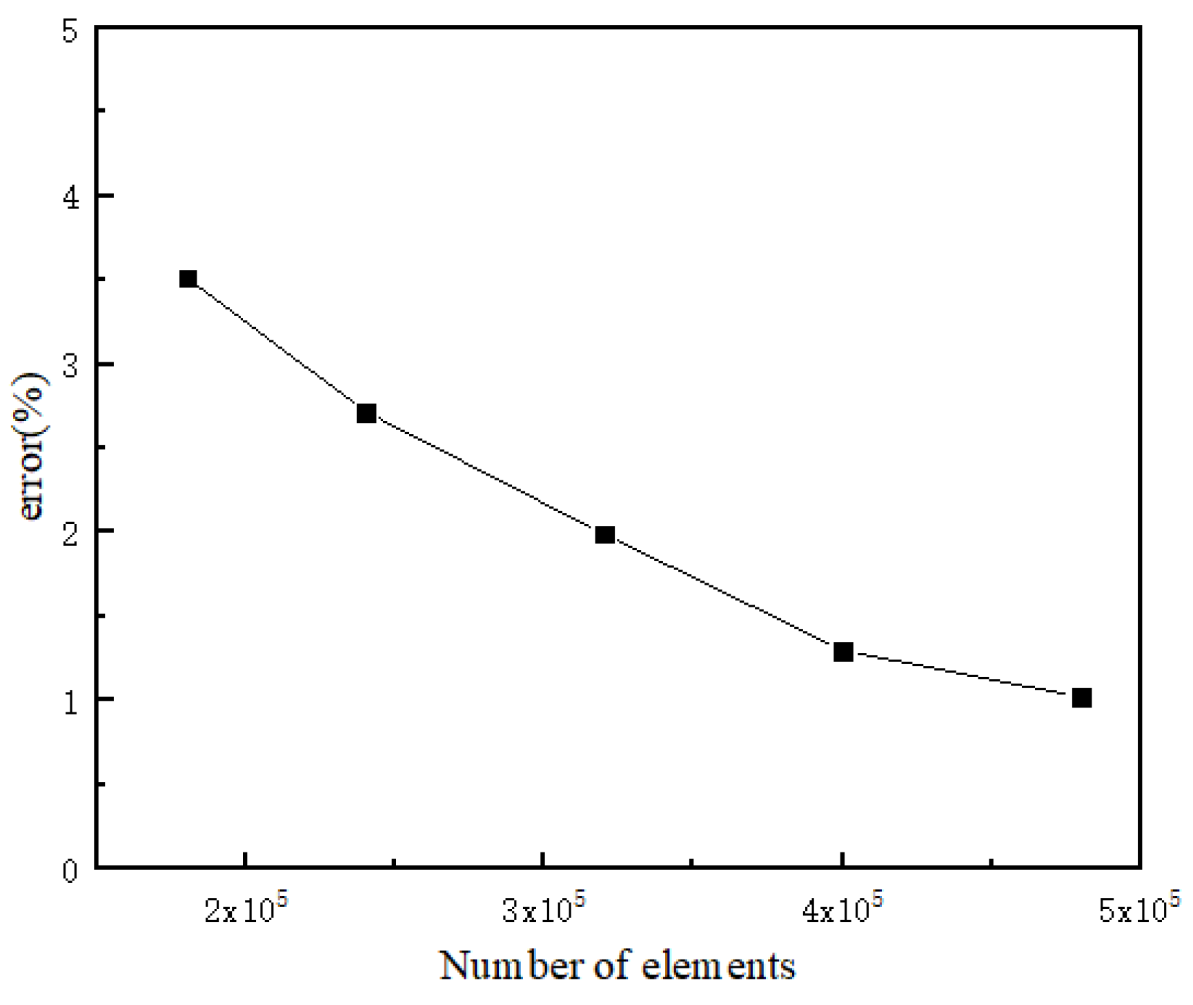
3. Numerical Procedure

The micronozzle operating regime depends on the ratio of the outlet pressure p2 to the inlet pressure p1. When p2 is equal to the ambient pressure and p2/p1 is equal to or less than a critical pressure ratio ηcr, the flow becomes sonic at the nozzle throat and it continues accelerate in the diverging section. The flow is fully expanded and a supersonic flow velocity forms at the nozzle exit. This is the normal operating regime of a supersonic nozzle and is desirable in many applications. Moreover, ηcr is a significant value for analyzing the flow in the nozzle as it changes from a subsonic to a supersonic velocity. ηcr can be calculated using the following expression from a one-dimensional isentropic relation:
η c r = p 2 p 1 = ( 2 k + 1 ) k k 1 = 0.487
The physical model and grid model in this paper are shown in Figure 1. It is a typical convergent–divergent nozzle and is based on the shape parameters of the nozzle used in the experimental study of Rothe [19] and the numerical study of Kudryavtsev et al. [3]. The angles of the converging and diverging parts are α = 45° and β = 20°, respectively. The nozzle throat half-width h is 100 µm. Local grid refinement was carried out in the convergent part, divergent part and the nozzle throat. The simulation was carried out in the fully expanded condition and the flow was assumed to be steady and two-dimensional. The flow field of argon was driven by the pressure ratio of the outlet and inlet, and the inlet pressure was 101,325 Pa, with the initial outlet and ambient pressure of 3739 Pa. The wall temperature was set to 300 K. The average velocity at the throat was near the local speed of sound c* = k R g T = 337 m/s, with the Reynolds number Re = ρuh/μ equaling 178. It was regarded as a laminar flow when the Reynolds number in the nozzle throat was less than 1000 [20]. The flow was assumed to be compressible and the density-based solver was employed. The convective terms were calculated based on a MUSCL (monotonic upstream-centered scheme for conservation laws) reconstruction, and the flow variable unit centered on the boundary of the grid was reconstructed with third-order accuracy [21]. The Roe-FDS was selected as the flux type. The double-precision floating point operation was chosen. Moreover, the convergence criterion for iteratively solving continuity, momentum and energy equations was set at 10−8.
The following assumptions were used for the discrete phase. On the one hand, it was assumed that the particles at the entrance were evenly distributed, and the type of nozzle wall was set to trap. This means that particles would be removed from the simulation if they hit the wall. On the other hand, one-way coupling was adopted owing to the volume fraction of particles being less than 10%; thus, the interaction between particles was ignored as well as the reverse influence of the particles on the fluid. The combined approach of computational fluid dynamics and the discrete particle method (CFD-DPM) was employed to investigate the motion characteristics of micro-/nano-particles in this study [22,23]. When submicron particles collided with the nozzle wall, they were considered to stick to the surface. Particles are seeded with the gas velocity at the left boundary of the simulation domain. All numerical simulations were carried out with the commercial software package ANSYS FLUENT15.0.

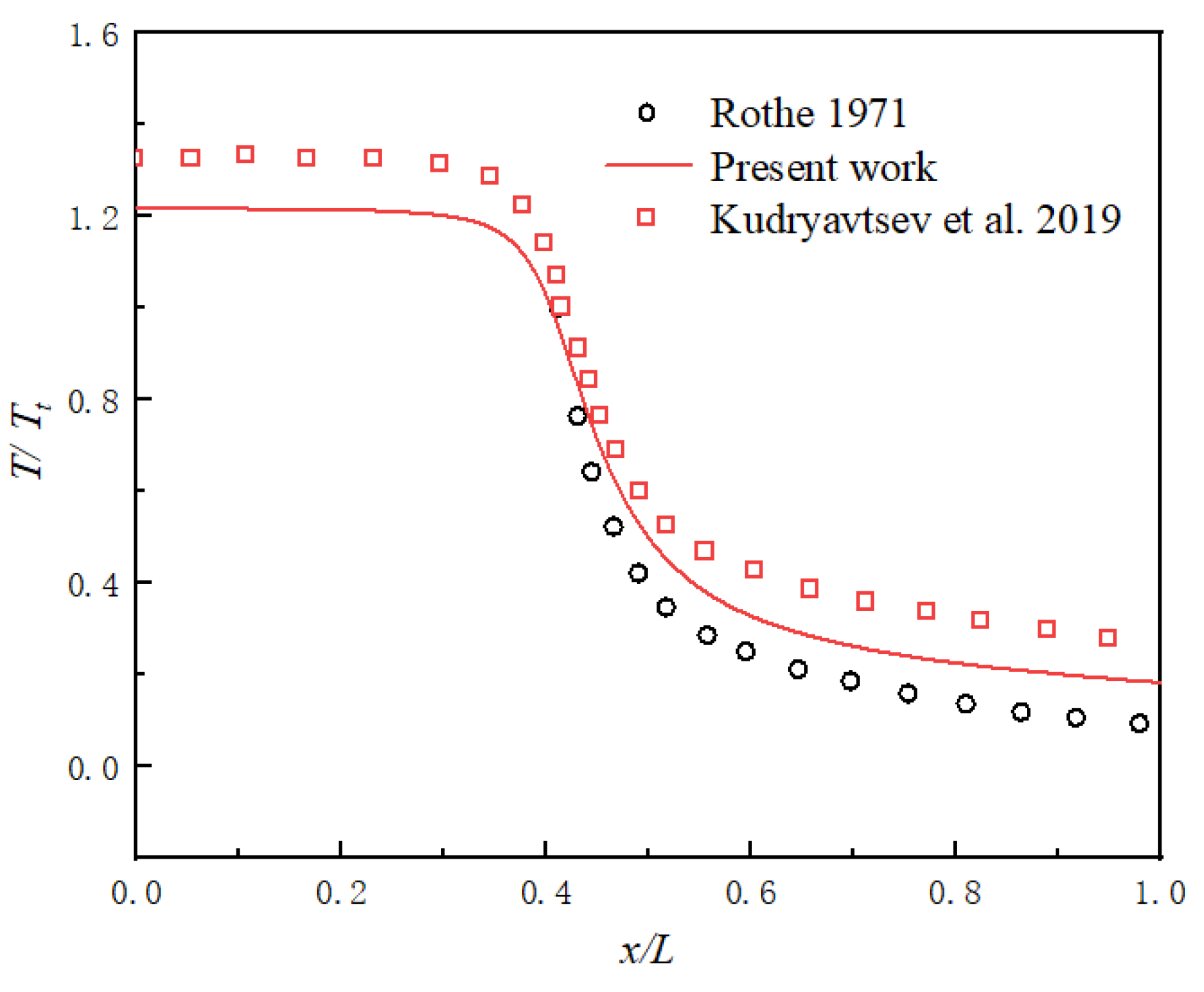
4. Validation of Solvers

Figure 2 shows the distribution of the dimensionless gas temperature along the micronozzle centerline. From the inlet to the convergent section, there was a slight decrease in T/Tt. When the gas moved to the nozzle throat, there was a sharp drop in T/Tt from 1.1 to 0.4, approximately. Thus, it can be suggested that there was a slight dependency on temperature distribution in x/L = 0.3–0.6. As can be seen, the predicted dimensionless gas temperature along the micronozzle centerline agrees favorably with the result of Kudryavtsev et al. [3] and the experimental results obtained by Rothe [19] using nitrogen. Kudryavtsev et al. [3], using N-S equations for a numerical simulation, found the same flow condition as our present work, while the region of their model is larger than that of our model due to their adding a small part of ambient space near the nozzle outlet in their work. Therefore, we can conclude that the numerical simulation of gas with rarefaction effects in a micronozzle can be acquired using compressible N-S equations in addition to the velocity slip and temperature boundary conditions.
A series of computations for five different grid sizes of 180,000, 240,000, 320,000, 400,000 and 480,000 were performed to ensure the production of the grid-independent solution in Figure 3. Comparing the gas velocity at the throat under these numbers of grids with the calculated local speed of sound c*, it was found that when the number of grids is more than 400,000, the deviation is less than 1.3%. However, when the number of grids contains less than 400,000, the deviation is greater than approximately 2%. Comprehensively considering the computational efficiency and precision, we deemed 400,000 grids to be sufficient for the present numerical simulation.

5. Results and Discussion

5.1. Flow Field Characteristics in the Micronozzle

Figure 4 show the isolines of the Mach number (Ma) and temperature (T) in the fully expanded flow fields of the micronozzle. As can be observed in Figure 4a, Ma keeps growing. In the convergent section, Ma is less than 1 (Ma ≈ 0.4), and it is a subsonic flow. As the cross-section of the nozzle decreases gradually, the gas velocity increases, and Ma is about 1 at the nozzle throat. After the gas flow expands along the micronozzle in the divergent section, the gas velocity continues to increase with Ma > 1. The results suggest that Ma, as well as T, has the opposite changes (Figure 4 and Figure 5). Ma is at the highest value around the nozzle outlet, where T is the lowest due to the thermodynamic energy being converted into kinetic energy in the flow fields. In accordance with the gas equation of state and the energy equation, the ideal gas flow velocity is restricted to U m a x = c 0 2 / ( γ 1 ) , where c0 is the speed of sound under stagnation conditions, as mentioned by Shershnev and Kudryavtsev [24]. Figure 4a also shows a thick boundary layer in the diverging part of the nozzle, which is a typical feature of the small Reynolds number nozzle.
The centerline Mach number and gas temperature distributions are illustrated in Figure 5. As T decreases, the viscosity coefficient of gas decreases, which hinders the development of a boundary layer and promotes gas expansion. Furthermore, the effect of rarefied gas increases owing to the decrease in the gas density. Therefore, the wall viscous effects on the nozzle flow increase and the boundary layer gradually becomes thicker, decreasing the velocity gradient near the outlet. Ma is approximately 4.2 in the nozzle outlet in Figure 5, which is near the theoretical value of the isentropic condition. It can be concluded that the boundary layer affects the Mach number distribution along with the change in temperature and gas density.
The characteristics of the flow fields in the micronozzle are discussed above. There are considerable changes in the parameters, such as gas velocity and temperature, thus affecting the velocity and trajectory of submicron particles.

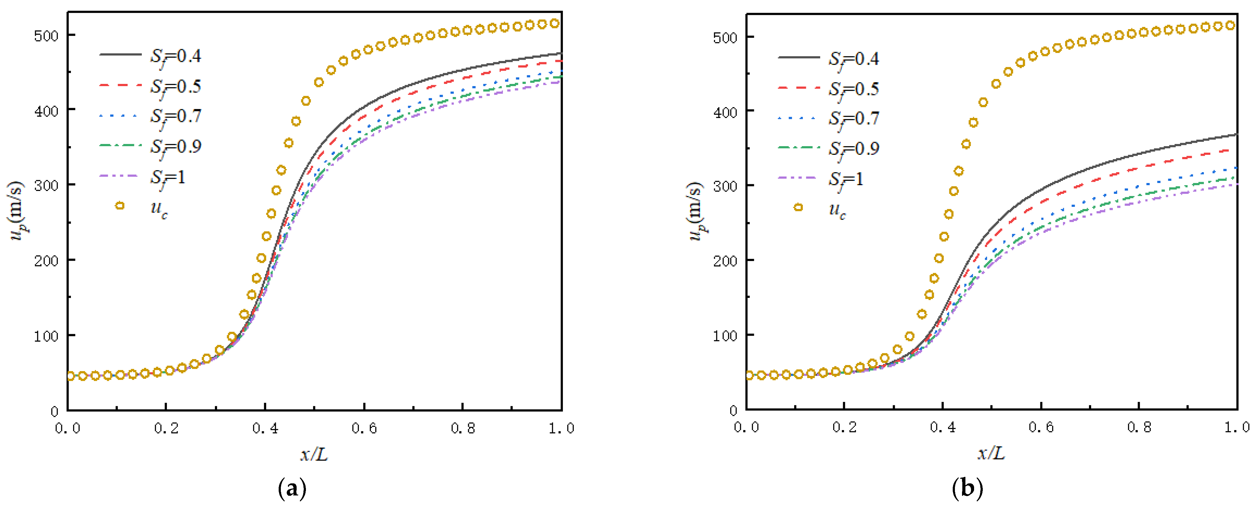
5.2. Distributions of Non-Spherical Submicron Particle Velocity

Figure 4b shows the large temperature difference in the micronozzle. Particles tend to move from the higher-temperature area to the lower-temperature area through thermophoresis when there is a relatively large gradient in the fluid temperature. The thermophoretic force is formulated as [25]:
F T = 4.5 π μ 2 ρ d p 1 1 + 3 2 λ d p C s C p + 2.48 2 λ d p 1 + 2 C s C p + 4.48 C s C p T T
where Cs represents the thermal conductivity of air, Cp represents the thermal conductivity of the particle and λ represents the mean free path. According to the temperature distribution in Figure 4b, there is a more than 200 K temperature difference in the nozzle which induces the thermophoretic force to affect the particles. At present, the influence of the thermophoretic force on submicron particle focusing in a micronozzle is vague. Therefore, we compared the velocity in the y-direction (up_y) of the particle (dp = 0.6 µm) released from the same initial position under two working conditions in Figure 6. One condition is that the thermophoretic force acting on the particles is considered, where F = FT in Equation (8), and another condition is that the thermophoretic force is ignored, where F = 0.
The result shows that there is almost no effect of thermophoretic force on aerodynamic focusing, so the thermophoretic force can be ignored in this paper. The factor that determines particle focusing is inertial force, which will be discussed later.
Most particles are non-spherical, which leads to different aerodynamic properties [26,27]. According to the definition of the shape factor (Equation (13)), particles with smaller shape factors have lower sphericity. It is expected that those particles are more rod-like or disk-like in shape. Table 2 shows the sphericity of the regular-shaped particles.
The submicron particle velocity is obtained by injecting Al particles (ρAl = 2688 kg/m3) with different shape factors and sizes into the nozzle inlet, as shown in Figure 7. The gas velocity in the flow field centerline and the particle velocity are defined as uc and up, respectively. With the rapid growth in the gas velocity, particle velocities have different degrees of increase with different shape factors. up with Sf = 0.4 coincides relatively well with uc for dp = 0.3 µm, while this coincidence degree becomes lower as Sf increases. This implies that particles with small shape factors show a stronger momentum exchange between the gas and particles, which makes it easier for particles to be accelerated. As a result, the outlet velocity of particles with small shape factors is relatively greater. In addition, the difference between up and uc with a different Sf becomes more obvious with the increase in dp, because the shape factor has little effect on the particle velocity of small particles (Figure 7a,d). We can also observe that as the particle size increases, the coincidence degree becomes lower between up and uc, which means that large particles show poor airflow followability due to their large inertia.
In order to better understand the mechanism of aerodynamic focusing, we compared the velocity in the y-direction of the Al particle released from the same initial position with variable shape factors for dp = 0.7 µm in Figure 8. Here, uc_y is defined as the flow field velocity in the y-direction. With the increase in Sf, the gradient of up_y decreases in the diverging section of the micronozzle; in other words, up_y at the outlet increases, making the aerodynamic focusing more obvious. It can be concluded that by reducing the shape factors, the particle focusing is weaker, but the particle velocity can be higher. Figure 9 shows the particle velocity in the y-direction with Sf = 0.5 for dp = 0.7 µm using three kinds of material particles, Al, Ti and Cu. The densities are ρAl = 2688kg/m3, ρTi = 4506 kg/m3 and ρCu = 8880 kg/m3, respectively. It is observed that the heavier Cu particle is easier to focus. Therefore, by increasing particle sizes and particle densities, the particle focusing is stronger due to their gained inertia. Therefore, the decisive influence of the aerodynamic focusing of submicron particles is inertial force.

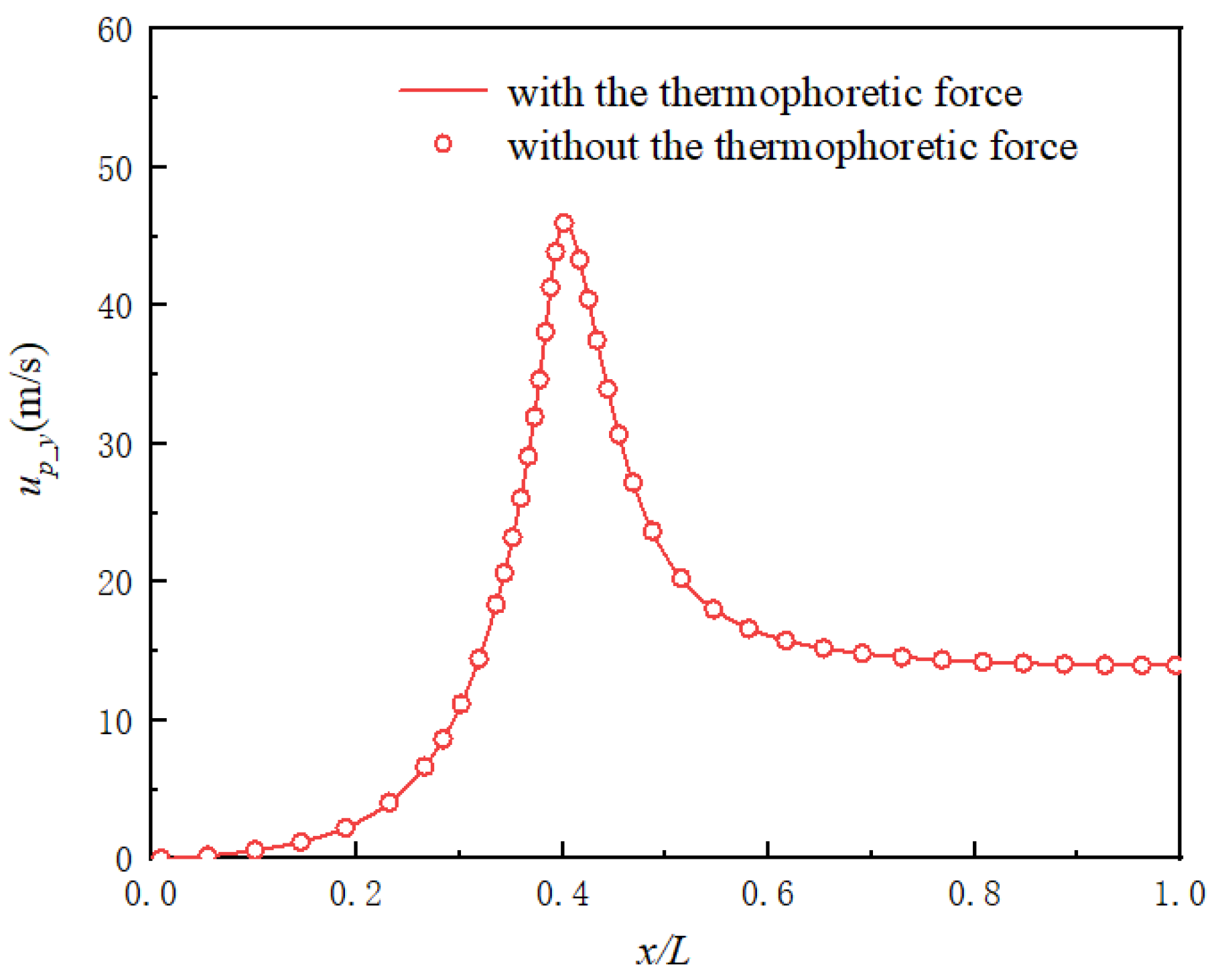
5.3. Effect of the Diffusion of Submicron Particles

To explore the changes in particle trajectories and the gathering effect in the fully expanded flow field, submicron particles evenly released at the inlet were tracked. Figure 10 shows the particle trajectory of Al with different submicron particle sizes and with Sf = 0.5. The streamline of the flow field is illustrated in Figure 11. The gas continues to expand and accelerate between the divergent section and outlet of the micronozzle, promoting submicron particle focusing. This implies that the drag force further increases with the gas flow as a result of the increasing particle velocity, weakening particle diffusion and enhancing the dynamic focusing of particles. As mentioned in the reference paper by Kudryavtsev et al. [3], when particle diameters increase, the particle trajectory undergoes the processes of repeated changes: the divergence process(I-a), the collimation process(I-b), a focused beam(I-c), the intersection process(II), a focused beam(III-c), the collimation process(III-b) and the divergence process (III-a). These processes can be divided into three stages. The divergence process(I-a), collimation process(I-b) and a focused beam(I-c) are included in the first stage; the intersection process(II) is included in the second stage; the divergence process(III-a), collimation process(III-b) and a focused beam(III-c) are included in the third stage.
In Figure 10, the particles diffuse slightly for dp = 4.5 µm owing to their large inertia. When dp is about 0.6–0.7 µm or 2.2–4.5 µm, a collimated or focused particle beam forms, both of which are desirable in the field of cold spraying. When dp = 0.7 µm and dp = 1.6 µm, aerodynamic focusing is observed, which is the best working state. Some relatively large particles converge so fast that their trajectories cross inside the nozzle, as shown in Figure 10d–f. If the particle trajectories cross, the nozzle exit is not in the best focus position.
Moreover, the critical diameter of Al particles for the occurrence of these processes is also different under various shape factors, as indicated in Figure 12. As Sf increases, the critical diameter becomes smaller. When Sf = 0.7, 0.9 and 1.0, a collimation process(I-b) occurs when dp is about 0.5–0.6 µm and an intersection process(II) occurs for dp = 0.7 µm. This explains why up_y is a relatively larger positive value at the nozzle exit for dp = 0.7 µm in Figure 8, indicating that the beam is defocusing. When Sf = 0.4 and 0.5, the collimation process(I-b) occurs when dp is approximately 0.6–0.8µm, which corresponds to the value of up_y, which is near zero in Figure 8, forming a focused particle beam.
Figure 13 demonstrates the diffusion range of the submicron particles of the nozzle outlet with Sf = 0.5 of particles when dp = 0.2 µm to 2.4 µm under three different densities. The exit radius of particle diffusion is represented as R. All three materials have two minimum particle diffusion radii which were marked with triangles, and at this moment particles are focused. In the first stage, when small particle trajectories change from diffusion to focus, R decreases rapidly as dp increases. The reason for this is that the increase in particle inertia and the flow drag force weakens the particles escaping from the axial direction, promoting the aerodynamic focusing of the particles. As dp continues to increase, the intersection process(II) for the particles appears, which is the second stage. R gradually increases at first and then decreases. This is because the position of the particle trajectory intersection moves towards the throat at first. After a particle size increases beyond a special particle size, the intersection moves to the nozzle outlet. This can be also observed in Figure 10d–f. At the third stage, the particle inertial force dominates the behavior of the submicron particles. The fluid drag force seems less obvious, so the diffusion radius of the particles increases slightly when dp increases. As the particle density increases, the critical diameter of the particle diffusion radius decreases in these three stages; that is, the diffusion radius of the particles changes at a smaller size. The change in R of the Al particles in the first stage is particularly more obvious than that of the Cu particles. On the contrary, the change in R of the Al particles is smaller in the third stage. Figure 12 and Figure 13 suggest that the different properties of particle trajectories with the same shape factor are determined by the particle size and particle density.
In conclusion, a converging–diverging micronozzle with a fully expanded supersonic flow is significant for the aerodynamic scheme of particle focusing in micro cold spay. The dynamic focusing of particles is the result of the competition between inertial force and drag force. Submicron particles with larger inertias will be useful in aerodynamic focusing in a higher drag force flow field.

6. Conclusions

This paper numerically demonstrates the flow characteristic and motion trajectory of submicron particles in a converging–diverging micronozzle using the Euler–Lagrangian method. The results show that a particle beam can be produced through the effect of aerodynamic focusing in the supersonic part of a fully expanded micronozzle flow field. The performance of the shape factor and particle density with various levels of inertia can be determined, allowing us to observe the resulting different particle velocities and trajectories. By increasing the particle densities and shape factors, the particle focusing is stronger due to their high inertia, while the particle velocity is smaller with a larger shape factor. The velocity of the particles with small inertia better coincides with their gas velocity compared with that of larger ones. The dynamic focusing of particles is the result of the competition between inertia force and drag force. Both of the two forces are beneficial for the aerodynamic focusing of particles. Furthermore, the position of submicron particle focusing changes with particle inertia. As the particle size increases, the position of the particle trajectory intersection moves towards the nozzle throat at first and then it moves inversely. Moreover, the thermophoretic force of the submicron particles has almost no effect on aerodynamic focusing in a micronozzle. The result of this study is important in technological applications, such as controlling the speed of the submicron particle beam in a micronozzle or forming a collimated submicron particle beam, etc. The diffusion and focusing process of particles can be affected by the particle shape. These results can be obtained by other simulation algorithms, such as discrete element methods (DEM), which can calculate the characteristics of the movement and rotation of particles with different particle shapes in the flow field. Further research on the effect of particles on the flow field and the interaction between particles will be considered.

Author Contributions

Conceptualization, Z.Y. and Y.W.; methodology, F.B. and Z.Y.; software, J.S. and Y.W.; validation, Y.W. and J.S.; resources, J.S. and Y.W.; writing, Y.W.; review, Z.Y. All authors have read and agreed to the published version of the manuscript.

Funding

This work was supported by the National Natural Science Foundation of China (No. 11972335, No. 11972334)

Conflicts of Interest

The authors declare no conflict of interest.

References

  1. Pourfattah, F.; Sabzpooshani, M. Thermal management of a power electronic module employing a novel multi-micro nozzle liquid-based cooling system: A numerical study. Int. J. Heat Mass Transf. 2020, 147, 118928. [Google Scholar] [CrossRef]
  2. He, L.; Hassani, M. A review of the mechanical and tribological behavior of cold spray metal matrix composites. J. Therm. Spray Technol. 2020, 29, 1565–1608. [Google Scholar] [CrossRef]
  3. Kudryavtsev, A.; Shershnev, A.; Rybdylova, O. Numerical simulation of aerodynamic focusing of particles in supersonic micronozzles. Int. J. Multiph. Flow 2019, 114, 207–218. [Google Scholar] [CrossRef]
  4. Darbandi, M.; Roohi, E. Study of subsonic–supersonic gas flow through micro/nanoscale nozzles using unstructured DSMC solver. Microfluid. Nanofluidics 2011, 10, 321–335. [Google Scholar] [CrossRef]
  5. Israel, G.W.; Gerhard, W.; Friedlander, S.K. High-speed beams of small particles. J. Colloid Interface Sci. 1967, 24, 330–337. [Google Scholar] [CrossRef]
  6. Liu, M.; Zhang, X.; Zhang, G.; Chen, Y. Study on micronozzle flow and propulsion performance using DSMC and continuum methods. Acta Mech. Sin. 2006, 22, 409–416. [Google Scholar] [CrossRef]
  7. Cao, C.; Han, T.; Xu, Y.; Li, W.; Yang, X.; Hu, K. The associated effect of powder carrier gas and powder characteristics on the optimal design of the cold spray nozzle. Surf. Eng. 2020, 36, 1081–1089. [Google Scholar] [CrossRef]
  8. Akhatov, I.S.; Hoey, J.M.; Thompson, D.; Lutfurakhmanov, A.; Mahmud, Z.; Swenson, O.F.; Schulz, D.L.; Osiptsov, A.N. Aerosol flow through a micro-capillary. Int. Conf. Micro/Nanoscale Heat Transf. 2009, 43895, 223–232. [Google Scholar]
  9. Bhattacharya, S.; Lutfurakhmanov, A.; Hoey, J.M.; Swenson, O.F.; Mahmud, Z.; Akhatov, I.S. Aerosol flow through a converging-diverging micro-nozzle. Nonlinear Eng. 2013, 2, 103–112. [Google Scholar] [CrossRef]
  10. Shershnev, A.; Kudryavtsev, A. Numerical simulation of particle beam focusing in a supersonic nozzle with rectangular cross-section. J. Phys. Conf. Ser. 2019, 1404, 012042. [Google Scholar] [CrossRef]
  11. Lin, W.; Zhang, P.; Lin, J. Flow and heat transfer property of Oldroyd-B-fluid-based nanofluids containing cylindrical particles in a pipe. Processes 2021, 9, 647. [Google Scholar] [CrossRef]
  12. Shi, R.; Lin, J.; Yang, H.; Yu, M. Distribution of non-spherical nanoparticles in turbulent flow of ventilation chamber considering fluctuating particle number density. Appl. Math. Mech. 2021, 42, 317–330. [Google Scholar] [CrossRef]
  13. Song, J.; Liu, J.; Chen, Q.; Li, K. Effect of the shape factor on the cold-spraying dynamic characteristics of sprayed particles. J. Therm. Spray Technol. 2017, 26, 1851–1858. [Google Scholar] [CrossRef]
  14. Ye, Y.; Tu, C.; Zhang, Z.; Xu, R.; Bao, F.; Lin, J. Deagglomeration of airborne nanoparticles in a decelerating supersonic round jet. Adv. Powder Technol. 2021, 32, 1488–1501. [Google Scholar] [CrossRef]
  15. Liu, M.; Peskin, R.L.; Muzzio, F.J.; Leong, C.W. Structure of the stretching field in chaotic cavity flows. AIChE J. 1994, 40, 1273–1286. [Google Scholar] [CrossRef]
  16. De Vanna, F.; Picano, F.; Benini, E. A sharp-interface immersed boundary method for moving objects in compressible viscous flows. Comput. Fluids 2020, 201, 104415. [Google Scholar] [CrossRef]
  17. Ambruş, V.E.; Sofonea, V. Half-range lattice Boltzmann models for the simulation of Couette flow using the Shakhov collision term. Phys. Rev. E 2018, 98, 063311. [Google Scholar] [CrossRef] [Green Version]
  18. Haider, A.; Levenspiel, O. Drag coefficient and terminal velocity of spherical and nonspherical particles. Powder Technol. 1989, 58, 63–70. [Google Scholar] [CrossRef]
  19. Rothe, D.E. Electron-beam studies of viscous flow in supersonic nozzles. AIAA J. 1971, 9, 804–811. [Google Scholar] [CrossRef]
  20. Liu, Z.M.; Zhang, T. Numerical investigation on gas flow in Laval micronozzle. J. Aerosp. Power 2009, 24, 1556–1563. [Google Scholar]
  21. Celik, I.B.; Ghia, U.; Roache, P.J.; Freitas, C.J. Procedure for estimation and reporting of uncertainty due to discretization in CFD applications. J. Fluids Eng. 2008, 130, 078001. [Google Scholar]
  22. Bao, F.; Hao, H.; Yin, Z.; Tu, C. Numerical study of nanoparticle deposition in a gaseous microchannel under the influence of various forces. Micromachines 2021, 12, 47. [Google Scholar] [CrossRef]
  23. Zhang, H.; Li, G.; An, X.; Ye, X.; Wei, G.; Yu, A. Numerical study on the erosion process of the low temperature economizer using computational fluid dynamics-discrete particle method. Wear 2020, 450, 203269. [Google Scholar] [CrossRef]
  24. Shershnev, A.; Kudryavtsev, A. Kinetic simulation of near field of plume exhausting from a plane micronozzle. Microfluid. Nanofluid. 2015, 19, 105–115. [Google Scholar] [CrossRef]
  25. Talbot, L.; Cheng, R.K.; Schefer, R.W.; Willis, D.R. Thermophoresis of particles in a heated boundary layer. J. Fluid Mech. 1980, 101, 737–758. [Google Scholar] [CrossRef] [Green Version]
  26. Lin, W.; Shi, R.; Lin, J. Distribution and deposition of cylindrical nanoparticles in a turbulent pipe flow. Appl. Sci. 2021, 11, 962. [Google Scholar] [CrossRef]
  27. Hu, X.; Lin, J.; Guo, Y.; Ku, X. Motion and equilibrium position of elliptical and rectangular particles in a channel flow of a power-law fluid. Powder Technol. 2021, 377, 585–596. [Google Scholar] [CrossRef]
Figure 1. Micronozzle model and grid model.
Applsci 12 00343 g001
Figure 2. Distribution of the dimensionless temperature of gas along micronozzle centerline.
Applsci 12 00343 g002
Figure 3. The test of grid independence in the flow field of the micronozzle.
Applsci 12 00343 g003
Figure 4. Isolines of Mach number and gas temperature in a fully expanded micronozzle: (a) Mach number; (b) gas temperature (K).
Applsci 12 00343 g004
Figure 5. Centerline Mach number and temperature distribution in a micronozzle.
Applsci 12 00343 g005
Figure 6. The change in the particle velocity in the nozzle considering the effect of the thermophoretic force.
Applsci 12 00343 g006
Figure 7. Velocity of particles along the micronozzle axis with different shape factors for: (a) dp = 0.3 µm; (b) dp = 0.7 µm; (c) dp = 1.6 µm; (d) dp = 4.5 µm.
Applsci 12 00343 g007aApplsci 12 00343 g007b
Figure 8. Velocity in the y-direction of the particle released from the same initial position with variable shape factors.
Applsci 12 00343 g008
Figure 9. Velocity in the y-direction of the particle released from the same initial position with variable densities.
Applsci 12 00343 g009
Figure 10. Al particle trajectory in the micronozzle with Sf = 0.5 for: (a) dp = 0.3 µm (divergence process(I-a)); (b) dp = 0.6 µm (collimation process(I-b)); (c) dp = 0.7 µm (a focused beam(I-c)); (d) dp = 0.8 µm (intersection process(II)); (e) dp = 1.0 µm (intersection process(II)); (f) dp = 1.4 µm (intersection process(II)); (g) dp = 1.6 µm (a focused beam(III-c)); (h) dp = 2.2 µm (collimation process(III-b)); (i) dp = 4.5 µm (divergence process(III-a)).
Applsci 12 00343 g010
Figure 11. The streamline in a fully expanded micronozzle.
Applsci 12 00343 g011
Figure 12. Al particle with variable shape factors in different processes.
Applsci 12 00343 g012
Figure 13. Diffusion radius of particles at the nozzle outlet.
Applsci 12 00343 g013
Table 1. The previous studies on aerosol focusing in nozzles.
AuthorsParticle SizeMethodFindings
Israel et al. [5]0.12–1.3 μmExperiment1. Aerosol focusing is the result of the inertial effect.
2. Particle velocity is up to 190 m/s.
Akhatov et al. [8]100 μmExperiment and a mathematical modelThe Saffman force acting on aerosol particles becomes significant, causing a noticeable migration of particles toward the center line of the capillary.
Bhattacharya et al. [9]2–6 μmCFD numerical simulation1. The influence of the Magnus force on 2 μm diameter particles can be ignored compared with the Saffman lift force.
2. A silver particle velocity of 600 m/s can be reached and the aerosol beam width is as thin as 50 µm.
Kudryavtsev et al. [3]0.05–5.0 μmCFD numerical simulationParticle beam collimation occurred in two different ranges of particle sizes for the plane-shaped and axisymmetrical nozzle.
Shershnev and Kudryavtsev [10]0.05–5.0 μmCFD numerical simulationParticle beam collimation occurred in two different ranges of particle sizes in the nozzle with a rectangular cross-section.
Table 2. The sphericity of several regular-shaped particles.
Particle ShapeModelShape Factor (Sf)
Sphere Applsci 12 00343 i0011
Cube Applsci 12 00343 i0020.806
Disk-like(h = r) Applsci 12 00343 i0030.827
(h = r/3)0.594
(h = r/10)0.323
Rod-like(h = 3r) Applsci 12 00343 i0040.86
(h = 10r)0.691
(h = 20r)0.580
Publisher’s Note: MDPI stays neutral with regard to jurisdictional claims in published maps and institutional affiliations.

