Abstract
In order to ensure driving safety and comfort, it is necessary to figure out the complex interaction between continuous welded rail (CWR) and suspension bridges for high-speed railway. A spatial finite element model for a 1092 m main span suspension bridge was established based on the bridge-track interaction theory. A specific correction method was put forward to keep the rail in a zero-stress state when just laid. Three rail expansion joint (REJ) layout schemes were proposed according to practical engineering experience. Both static and dynamic analysis methods were used to evaluate the feasibility of these schemes. The results show that the REJ should be laid at the position with a distance away from the primary beam end, and the beam with more substantial integral stiffness should be preferentially selected. For the recommended scheme, the REJ expansion reaches more than 380 mm under expansion load. The factors affecting the REJ expansion from major to minor are temperature, earthquake, rail fracture, braking, and bending load. The superposition effect of the above factors is suggested to be considered in the selection of REJ range.
1. Introduction
With the large-scale construction of the railway in China, super-long-span suspension bridges have gradually been popularized and applied in high-speed railway construction [1], considering the engineering economic factors when crossing complex river systems and geology. Although the suspension bridge is known for strong crossing capacity, convenient construction, and beautiful appearance, the bridge and the CWR laid on it form a complex spatial coupling model. Hence the bridge-track interaction is inevitable. CWR on suspension bridges not only imposes the difficulties of CWR itself to the common long-span bridge but also gives rise to a series of other technical difficulties. Specifically, the nonlinear factors of line resistance, as well as the large displacement of the structure, the initial stress of the main cable and suspender, the cable sag, etc., should be considered in the design and calculation of CWR.
The track and large-span bridge have been investigated in different aspects, including: analytical algorithm of the bilinear resistance model [2]; nonlinear finite element model (FEM) [3,4,5,6,7]; nonlinear static analysis program using a truss model [8]; static and dynamic analysis of cable structures based on catenary cable element [9]; design optimization for primary beam shape and plate thicknesses of long-span suspension bridges [10]; and the distribution of rail longitudinal force on large-span bridges [11,12,13,14]. Additional rail forces, as permitted by different countries, for addressing bridge-track interaction are summarized in [15]. Nevertheless, most existing studies only focus on cable-stayed bridges, to the neglect of the suspension bridge. The latter will drive CWR to produce larger deformation under the load of the train, because of its flexible system, thus posing a huge challenge to the stability and comfort of high-speed railway. Therefore, it is necessary to figure out the interaction mechanism of CWR on suspension bridges.
REJ is a crucial structure of CWR. It consists of the stock rail and switch rail. The switch rails are fixed while stock rails expand. Under the ideal working condition, the stock rail and switch rail are always close to each other. It is beneficial to significantly reduce rail stress and coordinate bridge-track displacement. The limited bridge lengths with different configurations of rail and deck expansion joints are suggested in [16]. In terms of the REJ layout optimization, the position of the fixed pier is adjusted [17]. The relative position of stock rail and switch rail of REJ is swapped, and the laying length of small resistance fasteners is optimized [18,19]. In terms of dynamic characteristics, non-linear wheel-rail contact is considered [20,21]. A simplified REJ model under train load is established [22], and experiments on the dilation length [23] as well as the dynamic performance of REJ [24] are carried out to evaluate the service status of REJ on bridges. It can be seen from the previous studies that, most of the REJ layout optimizations only pay attention to the mechanical characteristics of the bridge and track structure under static loads, but neglect the extending-retracting response of REJ under dynamic loads. As the weak link of CWR, the layout of REJ should be optimized in view of not only the statics, but also the dynamics.
This work has two objectives: on the one hand, to explore the interaction between CWR and suspension bridge, based on a suspension bridge with a main span of 1092 m in South China And, on the other hand, to research the dynamic mechanical characteristics of REJ on the suspension bridge. Based on the above, an optimization method for choosing the installation location and range of REJ on the suspension bridge is put forward, to further improve the design method of CWR for high-speed.
The present paper is organized as follows: after setting forth the challenge of REJ on the super-long-span suspension bridge within this introduction, Section 2 presents the static and dynamic calculation theory and analytical model. Section 3 and Section 4 separately describe the static and dynamic characteristic results of REJ on the suspension bridge. After that, the next section offers a discussion on the layout position and range of REJ, followed by the conclusions.
2. Calculation Theory and Model
Compared to ordinary bridges, the design of CWR on suspension bridge has the following prominent characteristics: (1) Track resistance parameters are transformed from constant to nonlinear; (2) The calculation model is transformed from planar to spatial; (3) The calculation method is transformed from analytical calculation to FEM; and (4) The design method is transformed from strength control to strength-deformation dual control.
2.1. Finite Element Analysis Model
Analytical calculation method [25] can be used in the analysis of medium and short span bridges. Nevertheless, the differential equilibrium equation can neither consider the coupling effects of various factors nor the geometrical non-linearity for a suspension bridge, which has complex stress and deformation. Since FEM has the above two advantages, this paper adopts ANSYS (a commercial FEM software) to establish the spatial coupling model of CWR on suspension bridges based on bridge-track interaction. When calculating the dynamic responses of REJ under train load, ANSYS is used for preprocessing and postprocessing, while LS-DYNA is used for explicit dynamic solving.
2.1.1. Correction of Track Longitudinal Resistance
The space geometric position of the primary beam will change under Phase II dead load due to the low vertical stiffness of the suspension bridge. This will cause extra force in CWR. In practical engineering, the rail is in a zero-stress state, theoretically, when it is just laid. Therefore, it is necessary to modify the model.
Specific correction methods are as follows. Suppose the longitudinal displacement of the bridge deck is a. The longitudinal resistance curve corresponding to the bridge node should be revised. The modified resistance curve of the nonlinear longitudinal spring is shown as the solid line in Figure 1. The longitudinal resistance can be expressed as:
where D refers to rail-beam relative displacement, Fmax and u are respectively the limit force and slip displacement corresponding to the longitudinal resistance of track.
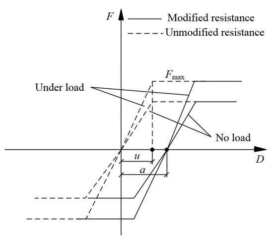
Figure 1.
Correction of track longitudinal resistance.
2.1.2. Ballast Track Model
Ballast track includes rail, fastener, sleeper, and ballast bed, which is a multi-layer structure. To simulate the bridge-track interaction more realistically, the longitudinal resistance of the fastener and ballast bed are considered in this model. The rail is simulated as beam element, and both ends of the rail are fully constrained. The vertical and lateral supports of the fastener are considered as linear springs (both are 60 kN/mm) [26]. The longitudinal resistance of fastener is considered as nonlinear spring element because of the nonlinear characteristics confirmed in [27]. The fastener’s constitutive relation is as shown in Figure 2a. The concrete sleeper is mainly to transfer the load of the rail to the ballast bed evenly, as well as to maintain the longitudinal and lateral geometry of the track. Considering its slender characteristic, it is simulated by the Euler beam element, and the sleeper node is connected with the fastener spring and the ballast bed spring simultaneously. The longitudinal and lateral resistance of the track bed is highly nonlinear [28]. It is simplified as a three-dimensional spring in this paper. The vertical support is simulated by linear spring (120 kN/mm), while the longitudinal and lateral constraints are considered as nonlinear springs (Figure 2b).
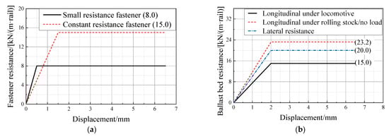
Figure 2.
Resistance-displacement diagram: (a) Type-V fastener; (b) Ballast bed.
According to the actual dynamic behavior of ballast track under longitudinal and vertical load, the vibration mass of ballast is considered in the longitudinal and vertical dimensions, respectively, as shown in Figure 3. The parameters are shown in Table 1. The vertical vibration mass of ballast is considered as the mass between adjacent sleeper cones described in [29]. To reduce the amount of calculation, this study considers the ballast track structure as a double-layer vibration model under the action of an earthquake. It is assumed that the vertical vibration mass of the ballast vibrates together with the sleeper.
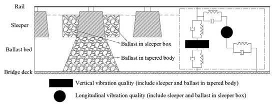
Figure 3.
Vibration quality model of ballast.

Table 1.
Vibration parameters of ballast track.
2.1.3. Suspension Bridge Model
When the load is applied to the primary beam, it is transferred to the suspenders, and then to the main cables and the towers. The track-suspension bridge interaction finite element model is shown in Figure 4. The calculation model is spatial. The interactions of the main cables, suspenders, towers and the primary beam are well simulated. The multilayer structures including rail, fastener, sleeper, ballast bed, and beam are considered in this model to calculate the continuous welded rail force and deformation accurately.
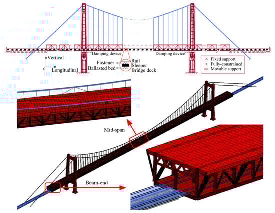
Figure 4.
Track-suspension bridge interaction finite element model.
The primary beam is a space truss structure. The chord, web, and cross members are simulated by the Bernoulli beam element, which can consider the shear deformation, and in which the members are rigidly connected. Steel bridge decks are simulated by shell elements. The suspenders, main cables, and wind-resistant cables are simulated by tension-only rod elements. The main cables are connected to the upper part of the tower by a rigid connection without longitudinal constraint. The anchor side of the cable is treated with full constraint. The main tower and the cross beam of the main tower are simulated by Euler beam elements connected from end to end in sequence. The suspension bridge is a semi-floating system. The primary beam and tower are coupled with vertical and lateral constraints, and damping devices are used longitudinally. The damping devices are modeled by linear springs, which are only activated under earthquake and braking load. The lateral and vertical stiffness of auxiliary piers is simulated by the linear spring element.
2.2. Calculation Parameters
2.2.1. Project Description
A super-long-span suspension bridge across the Yangtze River in China is modeled in this study, as shown in Figure 5. The upper layer of the bridge is laid with an 8-lane motorway, while the lower layer is laid with 4 high-speed railway lines. The main bridge of the suspension bridge is a two-tower five-span steel truss bridge with an arrangement of (84 + 84 + 1092 + 84 + 84) m and a span ratio of 1/10. The whole bridge is equipped with 2 main cables, 154 suspenders, and 4 wind-resistant cables. The main tower is 203 m high. The primary beam adopts a Warren-type truss stiffened beam. The height of the truss is 16 m and the length is 14 m for each segment. The widths of the lower and the upper deck are 30 m and 43 m, respectively. The longitudinal stiffness of damping devices is 200 kN/m. The rail consists of CHN 60, type-III concrete sleepers with type-V fasteners. The rail cross-sectional area is 77.45 cm2.
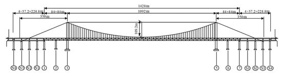
Figure 5.
Bridge span layout. (N1–4, 1, 2, 3, 5, 6, 7, S1–4 refer to the number of piers).
To reduce the influence of boundary conditions, a 4 m × 57 m concrete continuous beam bridge and 5 m × 32 m simply supported beam bridges are set on both sides of the suspension bridge, and a 150 m subgrade structure is set on both outer sides of the simply supported beam bridge. The main parameters of the bridge are shown in Table 2.
Table 2.
Main parameters.
2.2.2. Load Parameters
The parameters and load values are obtained from the actual situation and code [27]. The highest and lowest rail temperatures are 59.1 °C and −17.7 °C, respectively. The design stress-free rail temperature is considered to be 20 ± 5 °C. When calculating the expansion force of the rail, 15 °C is taken for the concrete beam and 25 °C for the steel truss beam. The dynamic bending stress caused by the train at the rail head (bottom) is 144.39 MPa (128.04 MPa). The adhesion coefficient between wheel and rail is 0.164. As the braking force is transferred along the vehicle segment by segment during braking, there is a certain time difference between each train segment. In this paper, the braking load length is 400 m. ZK standard live load and Ⅰ lane load are adopted (Figure 6). These two load diagrams are respectively common load diagrams of high-speed railway and expressway in China. The location of the concentrated load can be specified arbitrarily.
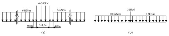
Figure 6.
Load diagram: (a) ZK live load; (b) Ⅰ lane load.
El-Centro seismic wave is selected in this calculation because of its large peak value and wide frequency band, and it is suitable for a foundation consisting of sand and stone. The seismic fortification intensity is 7 degrees and the peak acceleration is 0.15 g. The time-history curve of seismic acceleration with baseline correction is shown in Figure 7. The modified time-history curve does not drift from baseline, and the acceleration power spectral density curve and the power spectral density curve are close to the original one. It is assumed that the direction of seismic propagation is the same as the bridge trend.
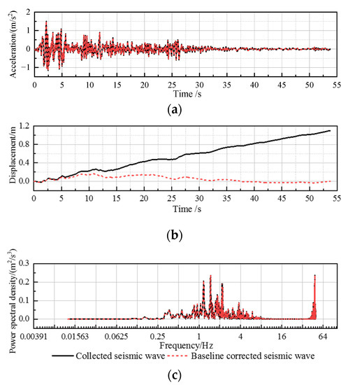
Figure 7.
Seismic time-history curve: (a) Time-acceleration; (b) Time-displacement; (c) Frequency-power spectral density.
The vehicle model is considered as a multi-degree freedom system composed of the car body, bogies, wheelsets, and spring-damping suspension device. The car body, bogies, and wheelsets are all simulated as rigid bodies. The car body and bogie have 5 degrees of freedom, including bouncing, swaying, nodding, yawing and rolling, while the wheelset has 4 degrees of freedom, including bouncing, swaying, yawing and rolling. The axle load of the vehicle is 17 t, and relevant vehicle mechanical parameters are referred to [30]. The speed of the vehicle is 250 km/h.
The wheel rail relationship is the key to describing vehicle-track coupling [31]. Wheel-rail normal contact is assumed as Hertz contact [21], and wheel-rail normal force is calculated with Hertz nonlinear elastic contact theory. Relevant calculation formulas refer to [30]. The wheel-rail tangential contact was simulated as friction contact, and the friction coefficient is set as 0.3.
2.3. Model Verification
In order to verify the suspension bridge model in this paper, the Block Lanczos Method [32] is used to calculate the vibration mode and frequencies of the suspension bridge, as shown in Figure 8. The fundamental frequency of the suspension bridge is 0.0953 Hz, and the fundamental period is about 10.49 s. The first mode of the suspension bridge is longitudinal drifting and anti-symmetric vertical bending. Because of the semi-floating system, the longitudinal stiffness of the primary beam is weak, leading to longitudinal drifting in the first mode. Table 3 shows the comparison of the frequency and mode shape with reference [33]. The relative error of bridge frequency calculated in this paper is less than 10%. The verified results indicate the reasonability of the suspension bridge model.
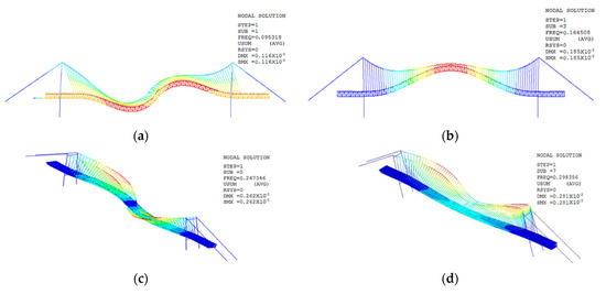
Figure 8.
The vibration modes of suspension bridge: (a) 1st mode; (b) 3rd mode; (c) 5th mode; (d) 7th mode.
Table 3.
Comparison of vibration modes.
3. Static Analysis of REJ on Suspension Bridge
3.1. Design Schemes of REJ
Because of the super-long span, the longitudinal force of rail is huge at the beam end, hence hard to meet the requirement in code [27]. To reduce the longitudinal force, REJs should be installed on the bridge. This study provides three rational schemes according to practical engineering experience, as shown in Figure 9. In these three schemes, the stock rails are laid with small resistance fasteners to the primary beam end.
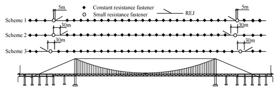
Figure 9.
Design schemes of CWR on the suspension bridge.
Scheme 1, switch rails are located at the primary beam, 5 m away from the beam end. Stock rails are located at the side span continuous beam across the beam gap. Scheme 2, the REJ is located at the primary beam, switch rails are 30 m away from the beam end. Stock rails are located at the continuous beam side. Scheme 3, the REJ is located at the side span continuous beam. Stock rails are located at the primary beam side, and switch rails are 30 m away from the beam end.
3.2. Rail Longitudinal Force with REJs
3.2.1. Under Expansion Load
The distribution of rail longitudinal force under expansion load (when the temperature reaches its maximum and minimum) is shown in Figure 10a. When the temperature drops, the maximum rail longitudinal tension is 975.55 kN in three schemes. While the temperature rises, the maximum longitudinal pressure is 996.94 kN, and the peak positions are all located at the active end of a simply supported beam close to the primary beam. The rail longitudinal forces at the primary beam end in three schemes are 39.2 kN, 240.8 kN, and 240.8 kN, respectively. Because the switch rail is disconnected from the stock rail, the longitudinal forces are zero at the point of switch rails. Under the condition of cooling and rising, the maximum rail longitudinal forces on the primary beam appear near the tower, which are 489.37 kN, 494.70 kN, and 493.99 kN, respectively.
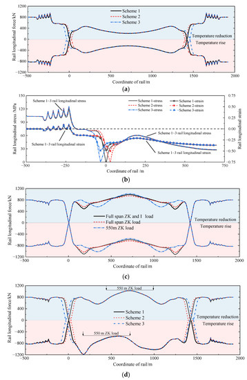
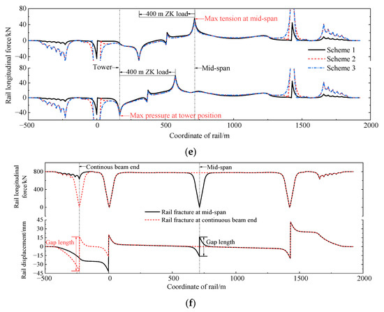
Figure 10.
Mechanical properties of rail: (a) Under expansion load; (b) Stress and strain distribution; (c) Under different vehicle loads; (d) Under bending load; (e) Under braking load; (f) Rail fracture.
The stress and strain relationship of CWR on bridge is very complex. The bridge is a symmetrical structure. Half of the rail stress and strain is analyzed, as shown in Figure 10b. The subgrade section is the fixed area of CWR (rail coordinates–500 m). The rail strain is zero, and the stress is related to the temperature variation of rail. At the laying position of the REJ, there is strain but no stress due to the free expansion of the stock rail. In other locations of the suspension bridge, due to the combination of beam-track interaction and the expansion load, the rail strain is less than the free expansion strain, and the rail stress is less than that at the subgrade.
3.2.2. Under Bending Load
Considering the action of double-line flexural loads of different lengths, the minimum load length is set at 550 m. Taking Scheme 1 as an example, the combined action of full span ZK and Ⅰ lane load, the single action of full span ZK load and 550 m mid-span ZK load are respectively considered. The longitudinal rail forces (the combination of the rail bending force and basic thermal force) under bending load (the superposition effect of flexural load and temperature variation) are shown in Figure 10c. When the rail temperature drops 42.7 °C, and the flexural load acts on the above three working conditions, the maximum longitudinal forces are 988.55 kN, 941.55 kN, and 1021.13 kN, respectively. When the rail temperature rises 44.1 °C, the maximum longitudinal forces are −1112.69 kN, −1042.00 kN, and −1021.06 kN, respectively, and the pressure peak appears at the position of the tower. Only the single effect of 550 m ZK load is considered in the following calculation because the loading length of the flexural load has a limited influence on the peak value.
To find the most adverse effect, the load is applied from one end of the primary beam to another. The results show that the maximum longitudinal tension appears when ZK load acts on the mid-span of the bridge, while the maximum pressure appears when the load of 550 m acts between the tower and mid-span. The rail longitudinal force corresponding to the most unfavorable condition is shown in Figure 10d. Under the temperature drop condition, the longitudinal tension peak values of rail are respectively 1021.13 kN, 1027.48 kN, and 1027.50 kN, all appearing in the mid-span position of the bridge. Under the temperature rise condition, the maximum rail longitudinal pressures are respectively 1179.27 kN, 1180.55 kN, and 1180.80 kN, all appearing at the position of the tower. The longitudinal rail force at the continuous beam active end is slightly reduced due to the laying of 30 m low resistance fasteners in Schemes 2 and 3. Compared to the rail expansion force, the rail bending force is larger, so the combination of the basic thermal force and rail bending force is adopted for subsequent checking and calculation according to [27].
3.2.3. Under Braking Load
When the braking load moves from the left end to the right end of the primary beam, there are two locations where the rail on the primary beam is in the most adverse state, due to the superposition of the basic thermal force, rail bending force, and rail braking force, as shown in Figure 10e. The peak value of the rail braking force appears at the load ends, and the distribution is antisymmetric along the load center. The maximum braking tensions of three schemes appearing at mid-span position are 55.65 kN, 51.21 kN, and 51.21 kN, respectively. The maximum braking pressures appearing at the tower position are 45.34 kN, 47.52 kN, and 47.52 kN, respectively. Because the REJ has a certain distance from the beam end, the peak of rail tension appears at the right beam end, and the peak of rail pressure appears at the left beam end.
3.2.4. Rail Fracture
When the rail fractures at a low temperature, the rail gap must be controlled to ensure driving safety. The probability of two or more rails fracturing at the same time is very low, so the fracture of only one rail is considered. When the rail temperature drops to −17.7 °C, the rail fracturing at the primary beam mid-span or the side continuous beam end is assumed based on the actual situation. Only Scheme 1 is calculated because of the nearly same rail longitudinal force at two assumed fracture positions. The longitudinal displacement distributions of rail under rail fracture conditions are shown in Figure 10f. The primary beam rail displacement distributions are the same under two rail fracture conditions, both antisymmetric along the mid-span. Due to the sudden rail fracture, the rail longitudinal force can be released and redistributed, and the rail displacement changes abruptly. Under two fracture conditions, the lengths of rail gaps are 32.67 mm and 57.62 mm, respectively, which are both lower than the standard requirement of 70.0 mm [27].
According to the analysis, because of the large stiffness and small temperature span, the additional forces of rails in approach bridges are small, and the strength and stability of rails can meet the requirements. In the primary beam area, the maximum rail pressure of the three schemes is (1180.80 + 47.52) kN, with the maximum compressive stress of 302.99 MPa after superposition of the dynamic bending stress of the rail. The maximum rail tension is (1027.50 + 55.65) kN, with the maximum tensile stress of 267.89 MPa after the superposition of the dynamic bending stress. The tensile and compressive stresses of the rail are both lower than the allowable stress of 351.50 MPa [27], meeting the requirements. The maximum longitudinal pressure of the rail is 1180.80 kN, which is less than the allowable pressure value of 1505.10 kN calculated by the unified formula [27]. To sum up, the strength, stability, and gap value of CWR in the three schemes all meet the requirements.
3.3. Displacement and Pier Force
For Schemes 1–3, the rail-beam relative displacements and pier longitudinal forces under expansion, bending, and braking loads are respectively calculated, as shown in Figure 11 and Figure 12.
Figure 11.
Rail-beam relative displacement: (a) Under expansion load; (b) Under bending load; (c) Under braking load.
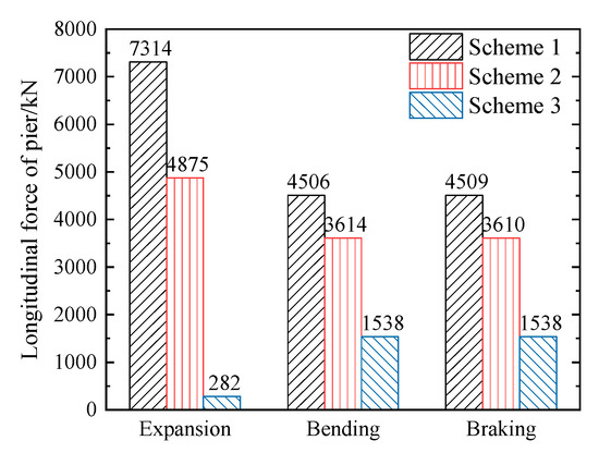
Figure 12.
Pier longitudinal force.
According to Figure 11, the rail-beam relative displacements from REJ laying position to beam end are large under the action of expansion, bending, and braking loads. For expansion load, as shown in Figure 11a, the maximum rail-beam relative displacement for each scheme is 251.83 mm, 233.05 mm, and 236.37 mm, respectively. Compared to Scheme 1, the peak values of rail-beam relative displacement of Schemes 2 and 3 are reduced by 7.46% and 6.14%. For bending load, as shown in Figure 11b, there is little difference between the maximum rail-beam relative displacements, which are 31.56 mm, 31.19 mm, and 31.70 mm, respectively. For braking load, as shown in Figure 11c, the maximum rail-beam relative displacements are respectively 18.34 mm, 7.58 mm, and 8.90 mm. The closer the laying position of the regulator is to the beam end, the greater the rail-beam relative displacements at the beam end area. Compared with Scheme 1, the relative displacements of Schemes 2 and 3 are reduced by 58.67% and 51.47%, respectively.
According to Figure 12, the longitudinal forces of the side span continuous beam bridge fixed pier for the three schemes are greatly different. For expansion load, the longitudinal force of bridge pier in Schemes 2 and 3 decreases by 38.40% and 38.34%, respectively, compared to Scheme 1. For bending load, compared to Scheme 1, the longitudinal force in Schemes 2 and 3 decreases by 25.74% and 25.94%, respectively. For braking load, the longitudinal force of bridge pier in Schemes 2 and 3 both increase by 81.65% compared to Scheme 1. According to the above comparison, the longitudinal force of the piers can be greatly reduced under expansion and bending load, and it is beneficial for the whole structure to share the braking force when REJ is laid at a certain distance from the beam end.
4. Dynamic Analysis of REJ on Suspension Bridge
4.1. Under Seismic Load
Figure 13a shows the structural dynamic responses under the El-Centro wave action. Under the action of seismic load, the expansion of REJ is basically consistent with the seismic wave acceleration trend, and the REJ expansion decreases when laid far away from the beam end. Figure 13b shows the fixed pier longitudinal force of the side span continuous beam of three schemes. The longitudinal force peak of the fixed pier increases when REJ is far away from the beam end.
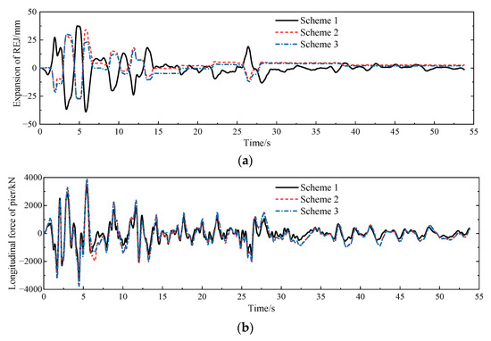
Figure 13.
Dynamic response of structures: (a) Time-history curve of expansion; (b) Time-history curve of pier longitudinal force.
According to Figure 14, as the REJ is far away from the beam end, the expansion decreases, and the peak values of the expansion are 37.62 mm and 34.21 mm for Schemes 1 and 2. Scheme 3 has a minimum value of 30.22 mm. The rail-beam relative displacement peaks at the beam end have the relatively same results, which are 41.46 mm, 35.34 mm, and 31.94 mm, respectively. The stock rails are laid at the primary beam or continuous beam, strengthening the contact between the primary beam and continuous beam. Scheme 1 has the weakest constraints, so the rail-beam relative displacement increases. The rail-beam relative displacement peak at the beam end is larger than the expansion peak.
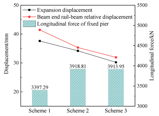
Figure 14.
Peak dynamic response.
As shown in Figure 14, the peak longitudinal forces of a continuous beam fixed pier enhance with the increasing distances between REJ and the beam end, which are 3397.29 kN, 3918.81 kN, and 3913.95 kN, respectively. Compared with Schemes 1–3 strengthen the interaction between the side span continuous beam and the primary beam, so that the longitudinal forces of the continuous beam fixed pier are increased.
4.2. Under Train Load
To highlight the dynamic effect of REJ irregularity, the vehicle-track-bridge coupling dynamic model only considers the influence of REJ irregularity without the random track irregularity. Measured irregularity in the REJ area is shown in Figure 15.
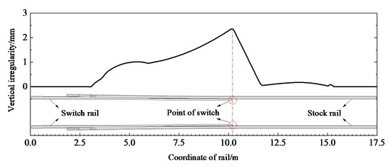
Figure 15.
Measured irregularity in REJ area.
Figure 16a shows the vertical acceleration curves of the switch rail and sleeper when the vehicle is traveling at 250 km/h. The peak vertical accelerations of rail corresponding to three schemes are 1210.00 m/s2, 880.49 m/s2, and 1028.50 m/s2, respectively. The peak accelerations of sleeper are 27.52 m/s2, 23.33 m/s2, and 20.38 m/s2, respectively. As the REJ in Scheme 1 is close to the beam end, the vertical vibration of the rail and sleeper will increase.
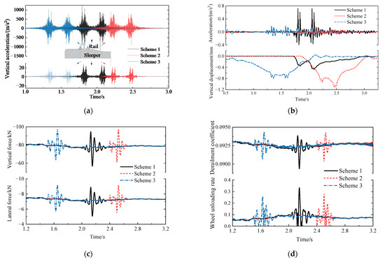
Figure 16.
Dynamic characteristics under train load: (a) Rail and sleeper; (b) Bridge deck; (c) Wheel-rail; (d) Security index.
Figure 16b shows the time-history curves of vertical bridge deck acceleration and displacement in the REJ area. The bridge deck vibration acceleration of Scheme 1 is significantly higher than that of Schemes 2 and 3. The peak vibration accelerations are 0.72 m/s2, 0.05 m/s2, and 0.193 m/s2, respectively. The peak vertical bridge displacements of the three schemes are 0.46 mm, 1.12 mm, and 0.80 mm, respectively. Because the REJs in Schemes 2 and 3 are close to the mid-span, the vertical displacement is large.
Figure 16c shows the time-history curves of vertical and lateral wheel-rail force. The peak vertical values are 94.67 kN, 96.73 kN, and 97.72 kN, respectively. The peak lateral values are 8.89 kN, 9.11 kN, and 9.20 kN, respectively. There is little difference between the wheel-rail vertical and lateral forces among the three schemes.
Figure 16d shows the time-history curves of derailment coefficient and wheel unloading rate. The maximum derailment coefficients corresponding to the three schemes are respectively 0.0938, 0.0946, and 0.0947, which are all lower than the requirement in code [34]. The peak values of the wheel unloading rate are 0.33, 0.28, and 0.26, respectively. From the above analysis, when the REJ is laid close to the beam end, the wheel-rail force fluctuates more violently, and the wheel weight reduction rate increases.
From the above analysis, it can be summarized that when the REJ laying position is closer to the beam end (Scheme 1) compared to laying Schemes 2 and 3, it is beneficial to reduce the vertical deformation of REJ, but this will increase the vibration acceleration of the rail, sleeper, bridge deck, and wheel unloading rate, affecting driving safety and comfort.
5. Optimization of REJ Layout
5.1. The Selection of REJ Schemes
The connection is simple adjacent and occlusal contact between ballast bed particles, where the main connection strength is friction resistance, which is easy to be overcome under vibration conditions. Under high traffic density, ballast particles will dislocate and migrate. The rail and sleeper may slide in the ballast bed under expansion and braking loads, which will loosen the ballast bed and reduce the longitudinal and lateral resistance of the ballast bed. In the meantime, the bridge deck under bending load will form a slope. The ballast particle tends to migrate to the middle of the primary beam. The ballast migration and bridge vibration deformation will cause adverse service behavior of the ballast bed.
The closer the REJ is laid to the beam end (Scheme 1), the larger the rail-beam relative displacements under expansion and braking loads are from the laying position to the beam end. The longitudinal pier force of the continuous beam bridge under expansion load will increase. Although the longitudinal force of side-span continuous beam pier under seismic load is reduced compared with Schemes 2 and 3, the rail-beam relative displacement and the REJ expansion at beam end are increased for Scheme 1. Under the action of the train load, although the structural deformation in the REJ area of Scheme 1 is small, the indexes such as vibration acceleration of rail, sleeper, ballast bed, and bridge deck structure are larger than those of Schemes 2 and 3. The stress and deformation are not conducive to the longitudinal and lateral resistance of the ballast bed and the maintenance of the track structure geometry. Therefore, Scheme 1 is not recommended in this paper.
When comparing Scheme 2 with Scheme 3 under temperature, earthquake, a trainload of the structure deformation, there is a significant reduction of the side span continuous beam fixed pier longitudinal force. Because the single-span length of continuous beam side span is 57 m, shorter than that of suspension bridge side span (84 m), and better integrity of box beam as well as smaller deformation under trainload, Scheme 3 is a better layout of REJ.
In summary, the optimal REJ scheme proposed in this paper is that of the switch rails located at the side span continuous beam, 30 m away from the primary beam end. Stock rails are located at the primary beam and over the beam gap. Thirty m of low resistance fasteners are laid on the stock rail side, to avoid the sleeper slippage in the ballast bed.
5.2. The Selection of REJ Range
There are many factors affecting the selection of REJ range. The expansions of REJ under expansion, braking load, and rail fracture are calculated in this section. REJ can release rail longitudinal force by the expansion of stock rail. The relative displacement of switch rail and stock rail is mainly composed of beam expansion and rail-beam relative displacement. Considering the most negative conditions, the relative displacements of switch rail and stock rail are calculated when the temperature of the steel truss beam, concrete beam, and rail drops 38.4 °C, 28.4 °C and 42.7 °C or rises 38.4 °C, 28.4 °C and 44.1 °C, respectively. Under the expansion load, the longitudinal displacement of rail in the optimal scheme (Scheme 3) is shown in Figure 17a.
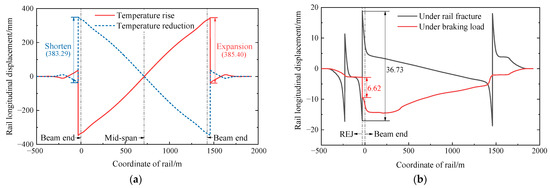
Figure 17.
Rail displacement: (a) Under expansion load; (b) Under braking load and rail fracture.
Under temperature drop and rise conditions, the rail longitudinal displacement is antisymmetric at the mid-span. The longitudinal rail displacement at the primary beam end is far more significant due to the large span of the primary beam. The expansion values are 383.29 mm and 385.40 mm for two conditions. Under the vertical load of the vehicle, the longitudinal REJ expansion is minimal and can be ignored due to the constraint of the side span continuous beam.
Due to the longitudinal damping devices set at the beam and main tower, the expansion value under braking load is much lower than that of expansion, seismic load, and other loads, which is 6.62 mm. For the rail fracture condition, the REJ expansion is 36.73 mm, as shown in Figure 17b.
From the above analysis, it can be seen that the factors affecting the REJ expansion from major to minor are expansion load, seismic load, rail fracture, braking load, and bending load. Although the probability of simultaneous action is very low, to ensure safe service, the superposition effect should be considered when selecting the range of REJ.
The suspension bridge is sensitive to wind [35] and other loads. These loads will cause large bridge deformation and have a significant impact on REJ expansion. Therefore, a certain amount of surplus should be considered for expansion. It is recommended that the range of REJ should be ±600 mm or more.
6. Conclusions
A spatial coupling model of CWR on a suspension bridge was established, based on bridge-track interaction theory and the actual situation of a suspension bridge with a 1092 m main span in China. Three layout schemes of REJ were put forward according to practical engineering experience. The interaction between CWR and suspension bridge was studied. The installation location and range of REJ were optimized by static and dynamic analysis methods. The following conclusions are drawn:
(1) The rail longitudinal force can be significantly reduced with REJ, which is a crucial structure of CWR. It is necessary to adopt REJ in the design of CWR on super-long-span suspension bridges.
(2) For a super-long-span bridge, the bending load usually plays a primary role in rail strength calculation compared to expansion load. The maximum tension appears in the middle of the primary beam, while the maximum stress appears at the main tower.
(3) The layout of REJ can reduce the CWR deformation under seismic load. The longer the distance between REJ and beam end is, the smaller the REJ expansion under seismic load is. Meanwhile, the longitudinal force of the side-span approach bridge fixed pier is increased.
(4) The vibration of the track and bridge in the REJ area will increase significantly. When the laying position of REJ is close to the beam end, it is beneficial to reduce the structure vertical deformation, but to increase the vibration acceleration of rail, sleeper, bridge deck, and vehicle as well as the wheel unloading rate, affecting driving safety and comfort.
(5) Due to the super long bridge span, the bridge expansion caused by temperature variation is significant. For the recommended scheme in this paper, the REJ expansion reaches more than 380 mm under expansion load. The factors affecting the REJ range selection from major to minor are the expansion load, seismic load, rail fracture, braking load, and bending load.
Author Contributions
Conceptualization, G.Z. and X.C.; methodology, G.Z.; formal analysis, W.L.; investigation, T.W. (Tielin Wang) and T.W. (Tao Wang); resources, X.C.; data curation, T.W. (Tielin Wang) and W.L.; writing—original draft preparation, G.Z. and T.W. (Tielin Wang); writing—review and editing, X.C., T.W. (Tielin Wang) and T.W. (Tao Wang); supervision, G.Z. and X.C.; project administration, X.C.; funding acquisition, X.C. All authors have read and agreed to the published version of the manuscript.
Funding
This research was funded by the National Natural Science Foundation of China (No. 51778050, 52178405), the Fundamental Research Funds for the Central Universities (No. 2018JBZ003, No. 2020JBZD013).
Institutional Review Board Statement
Not applicable.
Informed Consent Statement
Not applicable.
Data Availability Statement
Data is contained within the article.
Conflicts of Interest
The authors declare no conflict of interest.
References
- Qin, S.; Gao, Z. Developments and Prospects of Long-Span High-Speed Railway Bridge Technologies in China. Engineering 2017, 3, 787–794. [Google Scholar] [CrossRef]
- Dai, G.; Chen, G.; Zheng, R.; Chen, Y.F. A New Bilinear Resistance Algorithm to Analyze the Track-Bridge Interaction on Long-Span Steel Bridge under Thermal Action. J. Bridg. Eng. 2020, 25, 4019138. [Google Scholar] [CrossRef]
- Cai, X.; Liu, W.; Xie, K.; Tan, X.; Zhang, Q. Longitudinal Force Analysis and Structural Scheme Comparison for CWR on Long-Span Suspension Bridges. J. China Railw. Soc. 2021, 43, 160–167. [Google Scholar]
- Okelo, R.; Olabimtan, A. Nonlinear Rail-Structure Interaction Analysis of an Elevated Skewed Steel Guideway. J. Bridg. Eng. 2011, 16, 392–399. [Google Scholar] [CrossRef]
- Xie, K.; Zhao, W.; Cai, X.; Liu, H.; Zhang, H. Impacts of Initial Internal Force and Geometric Nonlinearity of Suspension Bridge on Bridge-Rail Interaction. J. Traffic Transp. Eng. 2020, 20, 82–91. [Google Scholar]
- Dai, G.; Ge, H.; Liu, W.; Chen, Y.F. Interaction Analysis of Continuous Slab Track (CST) on Long-Span Continuous High-Speed Rail Bridges. Struct. Eng. Mech. 2017, 63, 713–723. [Google Scholar]
- Xu, H.; Liu, H.; Lin, H.; Yan, H.; Wang, P. Influence Factors Analysis of Expansion and Contraction Force of Continuous Welded Rails on Long-Span Cable-Stayed Bridge. J. Railw. Eng. Soc. 2015, 32, 34–39. [Google Scholar]
- Papadopoulos, P.G.; Arethas, J.; Lazaridis, P.; Mitsopoulou, E.; Tegos, J. A simple method using a truss model for in-plane nonlinear static analysis of a cable-stayed bridge with a plate deck section. Eng. Struct. 2008, 30, 42–53. [Google Scholar] [CrossRef]
- Thai, H.-T.; Kim, S.-E. Nonlinear static and dynamic analysis of cable structures. Finite Elem. Anal. Des. 2011, 47, 237–246. [Google Scholar] [CrossRef]
- Kusano, I.; Montoya, M.C.; Baldomir, A.; Nieto, F.; Jurado, J.A.; Hernández, S. Reliability based design optimization for bridge girder shape and plate thicknesses of long-span suspension bridges considering aeroelastic constraint. J. Wind Eng. Ind. Aerodyn. 2020, 202, 104176. [Google Scholar] [CrossRef]
- Liu, J.; Qu, W.-L.; Pi, Y.-L. Active/Robust Control of Longitudinal Vibration Response of Floating-type Cable-stayed Bridge Induced by Train Braking and Vertical Moving Loads. J. Vib. Control 2010, 16, 801–825. [Google Scholar]
- Wang, P.; Zhao, W.; Chen, R.; Xiao, J. Bridge-Rail Interaction for Continuous Welded Rail on Cable-Stayed Bridge Due to Temperature Change. Adv. Struct. Eng. 2013, 16, 1347–1354. [Google Scholar] [CrossRef]
- Dai, G.-L.; Yan, B. Longitudinal forces of continuously welded track on high-speed railway cable-stayed bridge considering impact of adjacent bridges. J. Cent. South Univ. 2012, 19, 2348–2353. [Google Scholar] [CrossRef]
- Wang, P.; Liu, H.; Wei, X.-K.; Xiao, J.-L. Analysis of Longitudinal Force Regulation for CWR on Railway Cable-Stayed Bridge. J. Traffic Transp. Eng. 2013, 13, 27–32. [Google Scholar]
- Kang, C.; Wenner, M.; Marx, S. Background investigation on the permissible additional rail stresses due to track/bridge interaction. Eng. Struct. 2021, 228, 111505. [Google Scholar] [CrossRef]
- Ramos, Ó.R.; Schanack, F.; Carreras, G.O.; Retuerto, J.D.V. Bridge length limits due to track-structure interaction in continuous girder prestressed concrete bridges. Eng. Struct. 2019, 196, 109310. [Google Scholar] [CrossRef]
- You, R.; Tang, J.; Jiang, W. Study on the laying plan of continuously welded rails on super major bridge with large continuous beam. J. Shijiazhuang Railw. Inst. 2008, 21, 30–33,38. [Google Scholar]
- Cai, X.; Liu, W.; Xie, K.; Zhu, W.; Tan, X.; Gao, Y. Layout Optimization of Rail Expansion Joint on Long-Span Cable-Stayed Bridge for High-Speed Railway. Adv. Civ. Eng. 2020, 2020, 8855140. [Google Scholar] [CrossRef]
- Cai, X.; Miao, Q.; Li, D.; Xu, J. Mechanical analysis and arrangement study of REJ for CWR on cable-stayed bridge. J. Railw. Eng. Soc. 2018, 35, 36–41. [Google Scholar]
- Antolín, P.; Zhang, N.; Goicolea, J.M.; Xia, H.; Astiz, M.Á.; Oliva, J. Consideration of nonlinear wheel-rail contact forces for dynamic vehicle-bridge interaction in high-speed railways. J. Sound Vib. 2013, 332, 1231–1251. [Google Scholar] [CrossRef]
- Melo, L.R.T.; Malveiro, J.; Ribeiro, D.; Calçada, R.; Bittencourt, T. Dynamic analysis of the train-bridge system considering the non-linear behaviour of the track-deck interface. Eng. Struct. 2020, 220, 110980. [Google Scholar] [CrossRef]
- Tian, C.; Yin, M.; Wang, P. Considerations on Rail Expansion Joint Application of Continuous Welded Rail on Bridges. Railw. Eng. 2006, 2, 85–87. [Google Scholar]
- Garcia-Sanchez, D.; Sañudo, R.; Miranda, M.; Tárrago, N.; Lenart, S. Rail expansion devices and maximum dilation length in railway bridges. An experimental study. Eng. Struct. 2021, 229, 111605. [Google Scholar] [CrossRef]
- Zeng, Z.; Chen, X.; Jin, S.; Zhou, X.; Zhang, X. Dynamic Characteristic Test of Rail Expansion Joint on Cross-Xingyan Highway Bridge. Railw. Eng. 2007, 5, 79–80. [Google Scholar]
- Ruge, P.; Birk, C. Longitudinal forces in continuously welded rails on bridgedecks due to nonlinear track–bridge interaction. Comput. Struct. 2007, 85, 458–475. [Google Scholar] [CrossRef]
- CN-TB TB 10621-2014Code for Design of High Speed Railway, CN-TB: Beijing, China, 2014.
- CN-TB TB 10015-2012Code for Design of Railway Continuous Welded Rail, CN-TB: Beijing, China, 2013.
- Strauss, A.; Karimi, S.; Šomodíková, M.; Lehký, D.; Novak, D.; Frangopol, D.M.; Bergmeister, K. Monitoring based nonlinear system modeling of bridge–continuous welded rail interaction. Eng. Struct. 2018, 155, 25–35. [Google Scholar] [CrossRef]
- Zhai, W.; Lin, J.; Wang, K. Theoretical Simulation and Field Experiment on Vibration of Railway Ballast. J. Vib. Eng. 2003, 16, 5. [Google Scholar]
- Xin, T.; Yang, X.; Xiao, H.; Zhang, Q. Fatigue Analysis of Spring Clip Based on Vehicle-Track Coupled Model and Detailed Fastener Model. J. Cent. South Univ. 2016, 47, 4270–4276. [Google Scholar]
- Xu, L.; Zhai, W. A three-dimensional model for train-track-bridge dynamic interactions with hypothesis of wheel-rail rigid contact. Mech. Syst. Signal Process. 2019, 132, 471–489. [Google Scholar] [CrossRef]
- Kashiwagi, M. Block dimension and block number for the Block Lanczos method. J. Struct. Eng. 2004, 50, 229–234. [Google Scholar]
- Li, X.-Z.; Qin, Y.; Liu, D.-J. The Safety Control of Train Running on the Wufeng Mountain Yangtze River Bridge under Crosswind. J. Railw. Eng. Soc. 2018, 35, 58–64. [Google Scholar]
- CN-GB GB/T 5599-2019Specification for Dynamic Performance Assessment and Testing Verification of Rolling Stock, CN-GB: Beijing, China, 2019.
- Fenerci, A.; Øiseth, O.A.; Rønnquist, A. Long-term monitoring of wind field characteristics and dynamic response of a long-span suspension bridge in complex terrain. Eng. Struct. 2017, 147, 269–284. [Google Scholar] [CrossRef]
Publisher’s Note: MDPI stays neutral with regard to jurisdictional claims in published maps and institutional affiliations. |
© 2021 by the authors. Licensee MDPI, Basel, Switzerland. This article is an open access article distributed under the terms and conditions of the Creative Commons Attribution (CC BY) license (https://creativecommons.org/licenses/by/4.0/).