1. Introduction
Peoples’ expectations for 3D displays are very high. This is the result of science fiction movies showing high-tech devices that currently do not exist. To keep pace with the imaginations of customers, 3D displays should provide high-quality large 3D images that can be freely viewed from any angle. In this regard, digital holography has an advantage over other 3D techniques on the market. It renders an entire optical field of the 3D scene and provides all of the visual cues [
1,
2]. In a holographic display, a digital hologram is reconstructed by modulating the phase or amplitude of the illuminating beam with a Spatial Light Modulator (SLM). Such a device assures high-quality images. However, SLMs have a large pixel size and a limited number of pixels; thus, reconstruction of large images which can be viewed in wide angle and from many directions is not possible. Nevertheless, in the state of art there are solutions that overcome the limit of a single SLM with spatial and temporal multiplexing [
3,
4,
5,
6,
7]. For example, viewing angle can be extended using multiple SLMs arranged in a circular or planar configuration [
3,
4,
5]. Other works have employed high-speed SLMs and temporal multiplexing [
6,
7]. Displaying numerous holographic reconstructions in different directions enables viewers to see images from many viewpoints. Reference [
6] proposes a solution of multiplexing 1440 perspectives, while reference [
7] introduces the capability of having a 360° view.
Holographic displays must be designed based on the parameters of human vision. From this perspective, an interesting group of solutions are the holographic near-eye displays [
8]. They support binocular vision [
9], and provide colored [
10,
11] and speckle free images [
12]. Moreover, near-eye holographic displays allow focusing on different distances without a vergence-accommodation problem [
13], and provide the possibility of interactivity [
14]. From the immersion perspective, an essential parameter of near-eye displays is the size of the field of view (FoV), which limits the size of the image that can be observed. There are two main solutions enabling wide-angle viewing: decreasing the SLM pixel size with a 4F imaging system [
9], or employing spherical illumination [
15]. However, one of the significant limitations of wide-angle displays is the lack of fast and high-quality holographic content generation capability.
CGH methods allow for calculating the diffracted field from an object employing a computer [
16]. This calculation is possible by simulating the virtual representation of three-dimensional objects, mainly by using point cloud or polygon approaches [
17,
18]. Representation of objects based on the point cloud approach offers calculations with basic propagators, such as the Fresnel or Angular Spectrum (AS) methods [
19]. The wavefield of every point is computed with the help of these basic propagators and added one by one at the hologram plane. However, the realistic representation of an object demands that the number of points is counted in the millions. Moreover, the requirement of wide-angle viewing implies that the object is much larger than the hologram size. Hence, calculation of a CGH based on the point cloud approach will demand a significant amount of time. With the aim of reducing the calculation time, methods such as the wavefront recording plane (WRP) [
20] or the phase added stereogram (PAS) [
21] can be employed. Although WRP algorithms can reduce time calculation, they are not well suited for wide-angle view because the size of the object is much larger than the size of the hologram [
22]. On the other hand, Ref. [
23] has shown that the based-PAS algorithm is well suited for fast calculation of wide-angle view CGHs with densely populated clouds and occlusion culling of unseen areas. Despite these advantages, the PAS algorithm is still a relatively slow tool for obtaining a single high-resolution CGH for online viewpoint change.
To deliver end-to-end realistic perception, near-eye holographic displays should provide the capability of a continuous change of viewpoint, so that the spatial displacement between two consecutive viewpoints must be smaller than the size of the hologram. In the literature, the calculation of multiple viewpoints is based on the principle of Fourier hologram synthesis [
17,
24,
25,
26,
27]. This approach allows an easy manipulation of the multiple view projections of the object in the frequency space [
24,
27]. Nevertheless, these types of solutions are not suited for the dynamic nature of the near-eye holographic display. They are developed for small viewing angles and do not support continuous change of viewpoint as they require processing of large amounts of information. Recently, Refs. [
25,
28] have proposed a content generation solution where a new viewpoint hologram is created by reusing part of information from a previous view. Thus, there is no need to generate an entire hologram for two consecutive views when existing data can be used to generate a part of the next view. In this solution, a ray-tracing method was used to process the CGHs and free movement of the viewpoint position was achieved as a superposition of three separate operations: parallel shift, rotation, and front–back movement. It is worth noting that front and back movement solutions are implemented by using scaling of the hologram information [
29]. Unfortunately, the FoV of the proposed solutions is limited to 10°, which is a case of paraxial approximation. Moreover, high degradation of the 3D content is present when large distances or angles are employed [
28].
In this work, we address the hologram update problem for wide viewing angle near-eye holographic display, where the hologram plane is related to the eye position. As described in [
25,
28], the generation of holographic content from a previous viewpoint significantly accelerates the processing time of CGHs. However, unlike those works, we propose accurate and non-paraxial tools for numerical manipulation of the holographic content. In the presented solution, an overlap region is found as a projection of original holographic data on the tilted and shifted plane of a new viewpoint hologram. It is shown that reusing the overlap region is possible by shifting, rotating, and repropagating part of the previous CGH. In our approach, these operations are done in space and frequency domains by using the AS concept. We show that for wide viewing angle holograms, rotation operation can be replaced by frequency shift with optimized coefficient, which minimizes computation errors. This improves the processing time of reused information several times over. Subsequently, the missing region of the hologram is generated with the PAS algorithm [
23]. The combination of these two tools enables calculation of the next viewpoint. Performed numerical tests show fast and accurate calculations. Furthermore, it is shown that there is no degradation in image quality when a large number of viewpoints are generated. Thus, for continuous viewpoints change, it is sufficient to count only the first hologram frame. This is an advantage over the solution presented in [
28], where the recalculation of the full frame is necessary after several updates. The update method of this work is demonstrated by using numerical and optical experiments for a display of FoV of 62°.
The paper is structured as follows: the next section presents the principles of the proposed hologram update algorithm.
Section 3 and
Section 4 explain filling the blank part and reusing the overlap part in detail, respectively.
Section 5 presents numerical tests of the updated hologram quality and execution time.
Section 6 illustrates numerical and optical reconstructions of complex objects in the near-eye display. Finally, the conclusions of this work are presented in
Section 7.
2. Principles of Hologram Updating
The aim of a holographic display is to reconstruct an object which can be seen from any viewpoint. The viewer should be free to move their eyes in any direction (
x,
y,
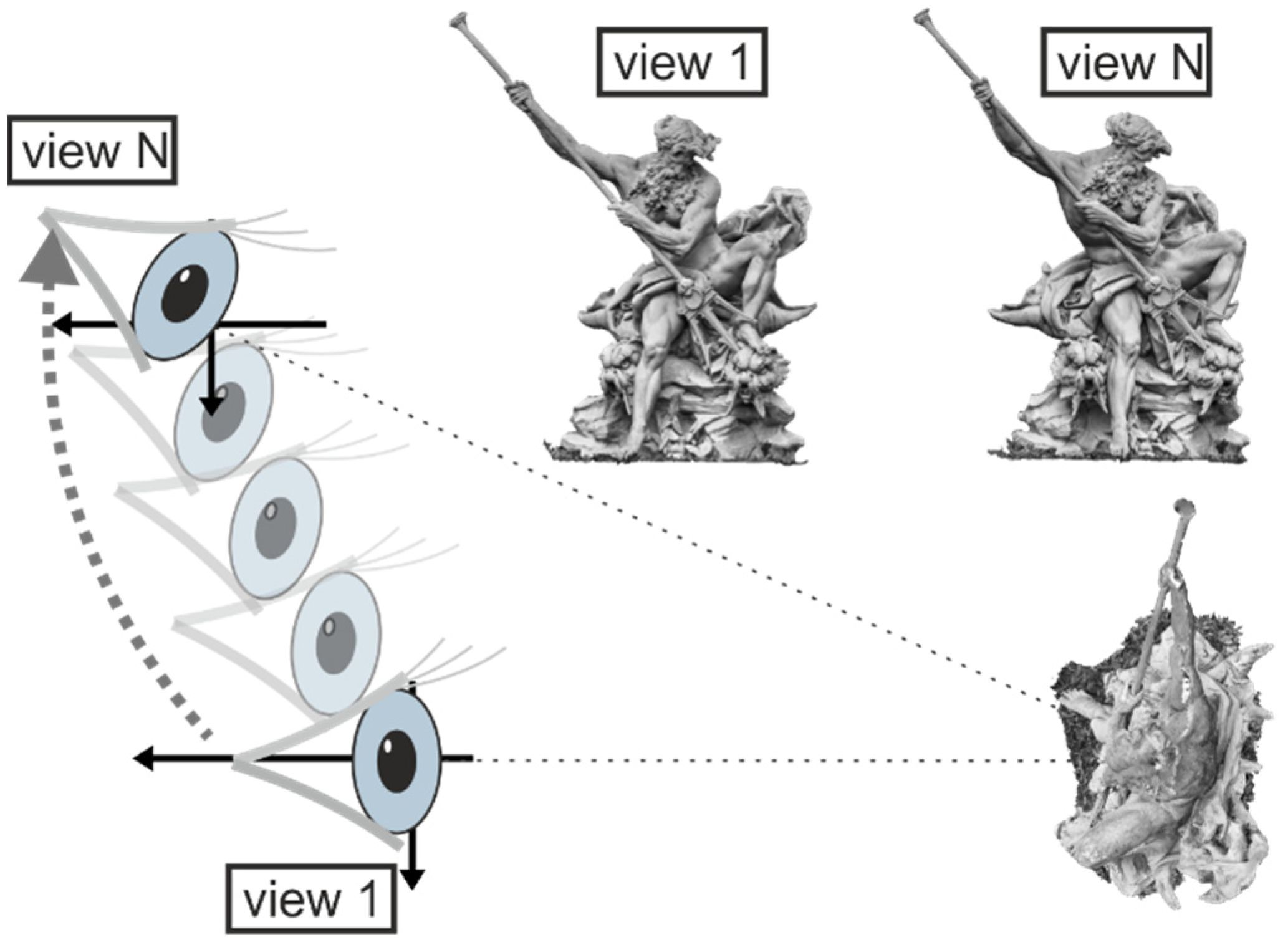
z-shift of a viewpoint) and observe corresponding perspectives of the object (rotation of the viewpoint). The viewer’s location in respect of the object determines the geometry for hologram computation. Therefore, when this geometry is altered, a different 3D image should be encoded.
Figure 1 illustrates the change in mutual object–hologram geometry as the eye position changes. At the first location, a viewer sees the front view of an object, while at the next, the viewer observes other parts of the object from a different angle. The straightforward way to accommodate this change is to recalculate the entire CGH for each geometry. However, the computation load can be very high. To reduce the computation time, it is necessary to use the view approximation method [
28,
30]. Unfortunately, known methods are based on paraxial approximation, which cannot be used for wide-angle displays.
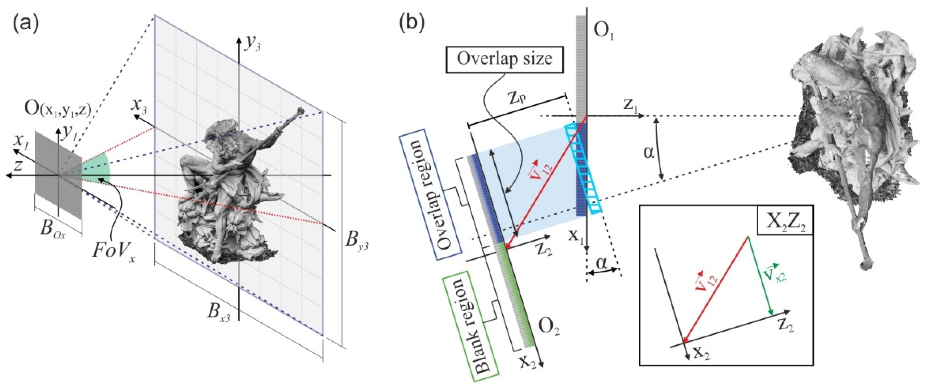
The proposed hologram update method enables faster content generation for a wide-angle holographic display system where the hologram plane is related to the eye position.
Figure 2a shows the studied geometry, for which the hologram plane (
x1,
y1) is located at a distance
z away from the image plane (
x3,
y3). The square hologram O has a size of
BOx×
BOx, where
BOx =
NxΔ,
Nx is the pixel size and Δ the pixel pitch. The pixel dimension determines the viewing angle as
FoVx = 2sin
−1(
λ/2Δ) and the corresponding size of the image,
Bx3 = 2
ztan(½
FoVx). In our research, a hologram of resolution 4K × 4K pixels and pixel pitch Δ = 0.62 µm is investigated. For the given pixel pitch and wavelength
λ = 640 nm, the
FoVx = 62°, while the physical size of the hologram O is 2.54 × 2.54 mm
2. The starting distance between the hologram and image plane is set to
z = 1000 mm, for which the image space is of size 1180 × 1180 mm
2.
Figure 2b illustrates data transfer of the hologram update method for two consecutive viewpoints. The investigated case considers viewpoint location change in the
z-x plane for simplicity. Two holograms, the initial O
1(
x1,
z1) and updated O
2(
x2,
z2), of size
BOx, correspond to the first and second viewpoint positions, respectively. Hologram O
2 is shifted and rotated with respect to the initial hologram O
1. The spatial shift from the center of O
1 to the center of O
2 is determined by the vector,
v12. For this geometry, the normal vectors of O
1 and O
2 are directed to the center of the observed object. Therefore, the rotation angle of hologram O
2 is equal to the angle α between optical axes
z1 and
z2. For a small change of viewpoint, the holograms O
2 and O
1, looking from the object position, share the common area. The common hologram area for the new viewpoint will be called the overlap region (blue part of O
1 and O
2), while the non-overlapping part will be called the blank region (green part of O
2). The division of hologram O
2 into the overlap and blank regions is the basis for the proposed hologram update algorithm, where the overlap information of hologram O
1 can be reused to fill the overlap region of hologram O
2 and only the blank region of hologram O
2 is filled with new data.
The size in pixels of overlap region of O
2 can be found from the transverse component of vector
v12 in the (
x2,
z2) coordinate system as
For clarity of presentation, let us define the corresponding overlap factor as
F =
Nxu/
Nx. To fill the overlap region of hologram O
2, the corresponding overlap region of hologram O
1 (blue part of O
1-see
Figure 2b) has to be found. Its number of pixels can be calculated as round(
Nxu/cos
α), where round(.) is a rounding operation. However, for the investigated case where
F > 0, the size of the overlap region of O
1 is
Nxu. The procedure of filling the overlap region has two steps: (i) rotation by angle α, marked in
Figure 2b with a light blue hatched box, and (ii) axial shifting of the rotated part by distance
zp. Both operations are realized by applying the AS concept. A detailed description of the developed algorithm is provided in
Section 4.
After the overlapping part is filled, the blank part of hologram O2 is determined by the segment-based PAS algorithm. Thus, in the PAS-based methods, the size of a hologram is a multiple of the segment size used. Therefore, the size of the resulting CGH can be larger than the blank area. The remaining pixels should be used to fill the edge region of the overlap area. In this paper, these pixels were not utilized, and were deleted. This was done purposefully in order to clearly present the performance of the update algorithm as a function of the overlap factor.
One part of the numerical test is provided for a hologram pixel pitch of 1 µm. This is due to the availability of numerical reconstruction tools. This test examines the full reconstruction of a 3D image. Despite using an efficient compact space bandwidth product [
31] implementation of the AS method [
32], we were unable to provide reconstruction for a pixel size of 0.62 µm.
3. Update of the Blank View Region
Calculation of CGHs can be carried out with different approaches depending on the geometry of the problem [
33]. For the case of wide-angle CGHs, it is necessary to process the enormous amount of wavefield information efficiently. Propagation-based techniques [
20,
34] are not optimal for CGHs with wide-angle, as they do not usually consider geometry where the object is much larger than the hologram. Recently, it has been shown that PAS-based algorithms enable efficient calculation of wide viewing angle CGHs [
23]. The PAS algorithm is based on the principle of dividing the hologram plane into smaller segments of size
Ns ×
Ns [
35,
36,
37]. At each segment, PAS approximates the spherical wavefront that comes from the
p-th point source of the object with a piece-wise plane wave [
36]. It is this property that enables efficient computations. Thus, the PAS algorithm was employed for filling the blank part of the hologram. Moreover, PAS enables easy calculation of hologram information directly from the frequency domain, which further improves execution time [
21,
36,
38].
With the aim of coding the proper perspective into the blank region, the rotation angle α on the
y-axis is applied to the object. Then, information from the point-cloud is coded into each segment in the frequency domain as follows:
where
is the distance from the
p-th point source to the center of the corresponding segment (
x2mc,
y2nc) within the blank region,
n = 1, …,
N, and
m = 1, …,
M indicate segment position over horizontal and vertical directions in the blank region, and
are the discrete local directional frequencies [
21] where Δ
fs = 1/
NsΔ is the frequency sampling,
⎿∙
⏌ is the rounding operation, and the angles
θpxnm,
θpynm are the incident angles of object beams on
x and
y directions according to the center position of the segment, respectively. Notably, Equation (2) allows representing the three-dimensional point source information as a set of two-dimensional Dirac deltas [
36,
38]. The position of each delta into
Õmn is given by the discrete frequencies shown in Equations (3) and (4). After placing all the Dirac deltas for the point-cloud distribution, the inverse FT is applied to obtain the corresponding segment.
The accuracy of the PAS algorithm depends on the size of the selected segment. When the size of the segments is smaller than the value based on sampling theory, noise reconstruction is introduced because the discretization error is increased according to the reduction of the number of pixels in the segment. On the other hand, when the segment size is larger to reduce the amount of discretization error, the reconstruction noise will be increased because of the condition from sampling [
36]. Thus, the proper size of a segment is a kind of compromise for PAS [
38]. The accuracy problem in PAS is improved by using accurate PAS (A-PAS) [
36]. A-PAS enlarges the segment in the frequency domain by an integer factor
q, which increases the frequency sampling and thereby reduces the discretization error. After applying the inverse FT to the enlarged segment, a submatrix of size
Ns is taken and the remaining part is disregarded.
The employment of the PAS algorithm for efficient calculation of wide-angle CGHs with occlusion culling has been shown in [
23], where it was shown that PAS enables efficient CGH calculations and occlusion culling of unseen areas. It was demonstrated that the occlusion-based PAS method can process CGHs with small pixel pitch (Δ = 0.62 µm), segment size
Ns = 512 and extension parameter
q = 3. This combination enables fast and accurate calculation of wide-angle CGHs with highly dense point clouds (up to 25 million points).
4. Update of the Overlap View Region
The second part of hologram updating for the next viewpoint is to fill in the overlapping area. In general, overlapping parts of original and updated holograms lie in different planes. Therefore, the data of the original hologram cannot be directly copied. However, the original data can be repropagated to the plane of the new hologram to fill the overlap region. This is faster than employing the PAS to generate a new CGH.
For the investigated case of wide viewing angles, the hologram is small. Thus, the calculation for updating the overlapping area should consider slight rotation of the initial hologram plane by the angle α and axial shift by a short distance,
zp. Both geometrical operations can be realized by propagation with the AS, where calculations are performed in frequency space. The corresponding calculations of data transfer from the initial hologram to the updated hologram plane (
x2,
y2) can be described as
where
Op1 and
Op2 are complex optical fields of the overlap areas at the initial and propagated planes, respectively. The tilde denotes FT operation, and
fz is the longitudinal frequency component, which is
To account for the tilt operation by the angle α, the components of the spectra
Õp1(
fx1,fy1) are projected onto
Õp1(
fx2,fy2) using a rotation matrix describing the new frequency coordinates
and
fy2 = fy1 as the rotation is around the
y-axis. To compute the overlapping data for the second hologram, the rotation operation is determined first, followed by propagation in the axial direction. Because of the non-linearity of the new spatial frequency coordinates obtained after the tilting operation, interpolation of the processed signal is necessary, which is time-consuming [
39,
40]. However, for the case of a wide-angle hologram, where angle α is small, the corresponding calculations of
Õp1(
fx2,fy2) can be simplified.
The spectrum casting can be represented as a frequency shift operation,
fx2 = fx1 + fdiff(
fx1,fy1), where
fdiff can be found by analyzing Equation (7). Notably,
fdiff is a function of the transverse frequency coordinates. However, for the case considered, we can find a constant value
fs approximating
fdiff with a small error within the entire range of spatial frequencies. To find the optimal value of
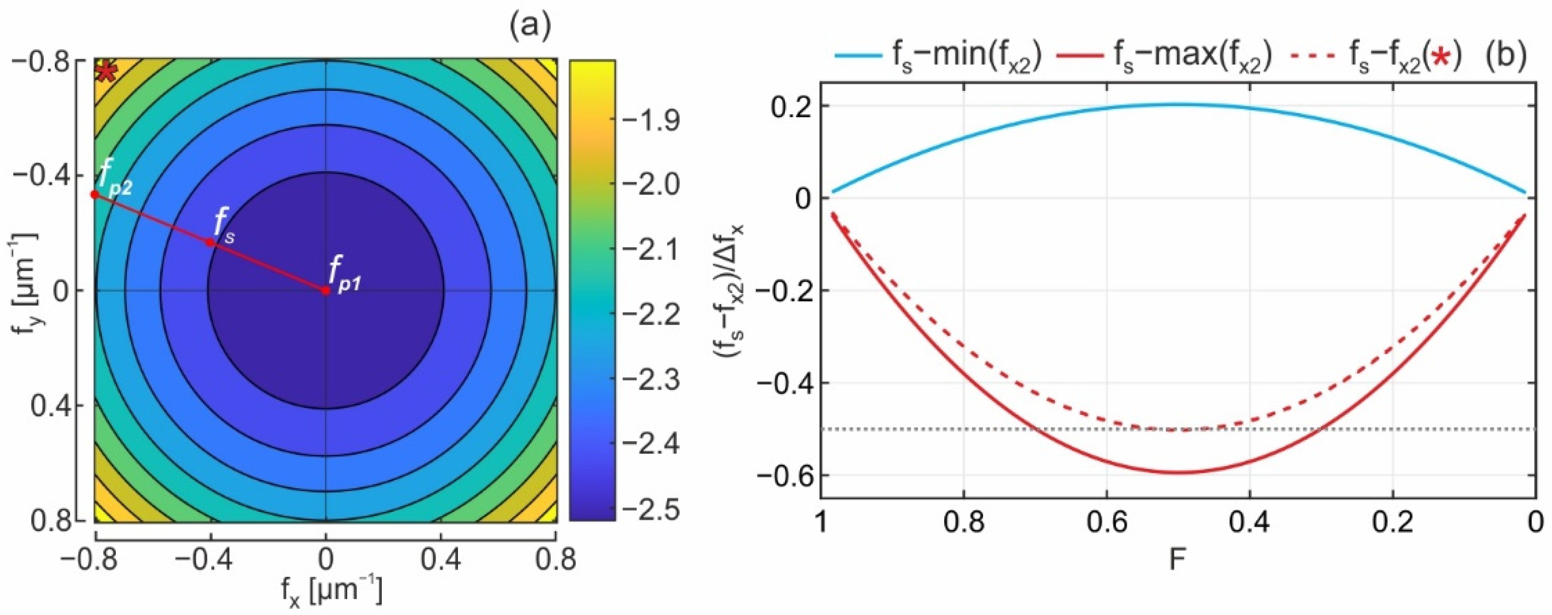
fs requires a closer look at the distribution of
fdiff shown in
Figure 3a. The presented distribution is normalized to the frequency sample size of Δ
fxu = 1/
NxuΔ. First, as can be noticed, the required frequency shifts are low; accordingly, the corresponding frequencies of the hologram can be placed in the correct frequency location by selecting proper
fs. Notably, the tilt operation should not give an error larger than ½Δ
fxu. Second, it should be noted that for wide-angle holograms, the point object is encoded in a small frequency area. For example, the hologram’s corner frequency corresponds to the object’s corner location in the FoV. Thus, we propose an approach where a major part of the hologram has relatively small errors, and the largest errors are obtained at the corner points. This does not mean that the center point will be reproduced with the smallest error. The concept behind this approach is presented in
Figure 3a, where minimal errors are obtained for frequencies of radius corresponding to the location of frequency shift of radius
fs, while the same errors will be generated for the corresponding frequency circle of
fp2 =
fdiff(1/2Δ 1/6Δ) and the center point
fp1. The
fs is calculated as a mean value of frequency shifts
fdiff of
fp2 and
fp1. Thus, the optimal frequency shift is given as
The graphical interpretation for selecting
fs within the frequency space is illustrated as the red line in
Figure 3a. For the chosen criteria, 82% of the FoV will have an approximation error that is smaller than the center point of the object. Accordingly, 82% of the image space has a smaller reconstruction error than obtained for the center point. The values of frequency shift
fs depend on the tilting angle α, which grows with the overlap parameter.
Figure 3b illustrates this effect and presents the minimal and maximal errors. Notably, the largest error is obtained at the corner of the FoV. To show the error magnitude there, a red dashed line has been added to
Figure 3b which corresponds to the point object for angular coordinates of (0.95
FoVx, 0.95
FoVy). Its frequency is illustrated in
Figure 3a with a star mark.
The distribution presented in
Figure 3a is calculated for the overlap factor
F = 0.5 which, as can be seen in
Figure 3b, is the least optimal case. As illustrated in
Figure 2, calculations of the update are carried out for the corresponding part of the hologram. For a smaller value of the
F factor, the size of the considered hologram region is smaller, and thus Δ
fxu increases. Accordingly, the corresponding shift error is smaller.
When determining
fs, the calculations of the overlap part can be written as
where
The proposed method of recalculating optical fields for different hologram positions introduces an error of frequency shift with acceptable magnitude. The proposed approximating method reduces the processing time of reused information by several times compared to the AS-based method. This significantly speeds up the recalculation of the overlap area.
5. Numerical Investigation of Hologram Update Algorithm
In this section, the test results on the accuracy and calculation time of the proposed hologram update algorithm are provided. For generation of CGHs and filling of their blank region, the A-PAS method was utilized with segment size
Ns = 512 and extension factor
q = 3. These parameters are used in the experimental section in
Section 6. Investigation of accuracy requires employment of the propagation tools for image reconstruction. In the case of wide FoV, for known numerical propagation algorithms an accurate recovery of the entire optical field of image space requires an enormous amount of RAM and calculation time. The approach proposed in this chapter is based on analyzing the reconstruction quality of several points that are mutually separated in space. This eliminates the need for calculating the entire image space. Only its corresponding fragments are reconstructed with the Rayleigh–Sommerfeld Off-Axis direct integration method (OADI) [
41]. The accuracy test had two parts: the first checked the quality of a single hologram update for different sizes of the overlap area, while the second analyzed the algorithm’s performance over hundreds of hologram update cycles. The calculation time was investigated on a PC with Intel i9-9900 and 64 GB RAM, without GPU and multithreading support.
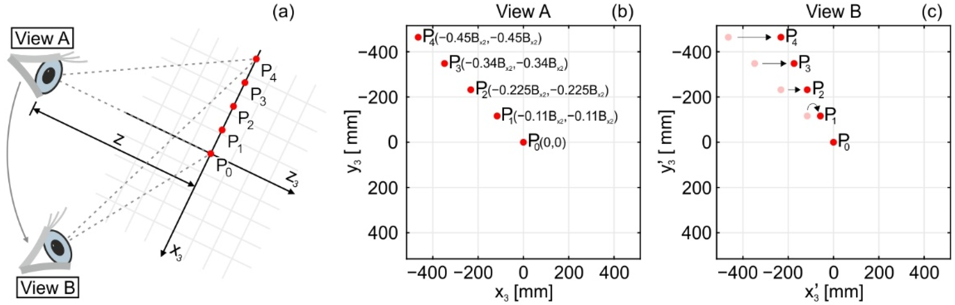
The accuracy of the proposed update method was quantified by reconstructing holograms of point sources. The investigated scene geometry is illustrated in
Figure 4a, where the viewpoints marked with the eye icon also represent the hologram plane. The test object consisted of five point sources, P
n, distributed linearly along the diagonal of the image space. The first point is center point P
0(0, 0,
z), while the last is off-axis point P
4(−0.45
Bx3, −0.45
Bx3,
z). All considered points are shown in
Figure 4b. Their coordinates are given according to the coordinate system of the starting viewpoint position, noted as ‘View A’ in
Figure 4a. The object plane is located 1000 mm away from the hologram plane. In the simulation, the viewpoint rotated horizontally around the center point, P
0. As a result, the positions of the other points were changed in relation to the hologram plane. Overlap factor
F describes the hologram displacement in a single step. After 1000 cycles, the hologram reached the ‘View B’ position. The perspectives of the object at ‘View A’ and ‘View B’ are presented in
Figure 4c.
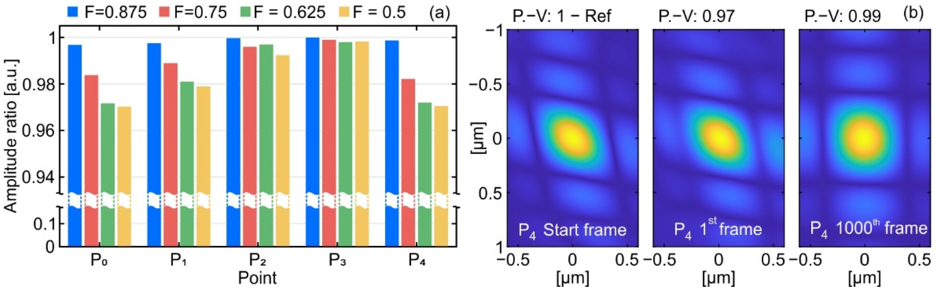
The first experiment examined the accuracy of a single hologram update cycle for different overlap sizes. As a measure of accuracy, the amplitude ratio of points reconstructed from an updated hologram and calculated with A-PAS was used. A similar approach has been applied to assess image quality loss due to the presence of optical aberrations [
42].
Reconstructions of each point were calculated for its focus plane. The hologram update method was tested for overlap sizes of factor
F: 0.875, 0.75, 0.625, and 0.5. The obtained results are presented in
Figure 5a, where the effect of optimization of the
fs can be noticed. The highest image quality was obtained for point P
3 and P
2, while points P
0 and P
4 had a similar level of update error regardless of the overlap size. In total, the amplitude ratio of every point exceeded 0.97. Thus, the updated hologram was accurate in its entire volume.
Figure 5b presents the direct comparison of reconstructed point P
4 from a starting hologram generated with the A-PAS algorithm and the proposed update method for 1st and 1000th frame, with overlap
F = 0.5.
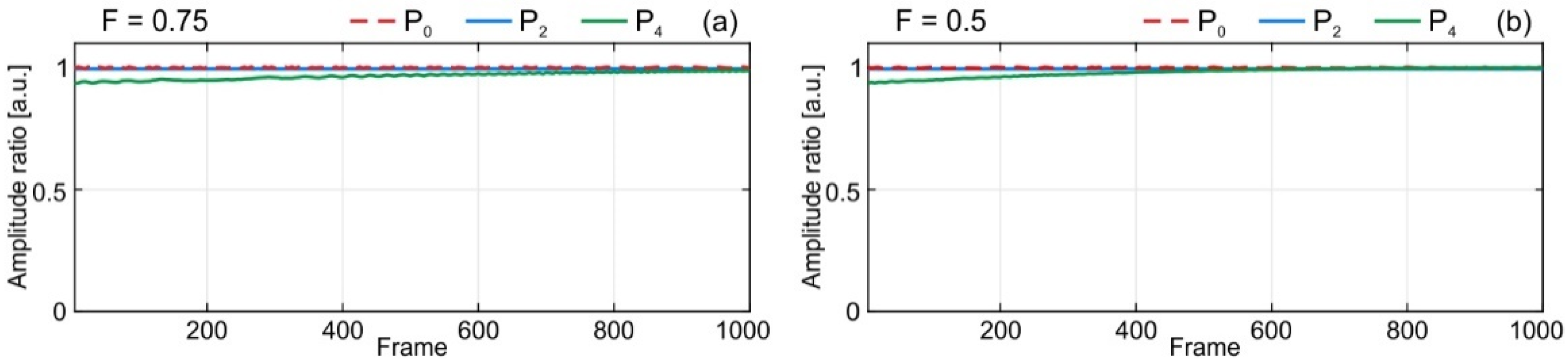
In the second test, the accuracy of the hologram update method was investigated for a large number of update cycles. The point distribution of the former experiment was used here as well. The test examined 1000 cycles of hologram update. To evaluate the image quality, every tenth frame was numerically reconstructed. In addition, for every tenth frame, the full CGH with A-PAS algorithm was generated and reconstructed as a reference. The test was evaluated for overlap factors
F = 0.5 and 0.75. The amplitude ratios for on-axis point P
0, midpoint P
2, and off-axis point P
4 comparing update holograms with the reference holograms are shown in
Figure 6.
The update algorithm remains stable after 1000 cycles. This shows that the proposed method preserves the high accuracy of the encoded object information. The amplitude ratio for midpoints is close to 1 during the entire test. For the off-axis point, the amplitude ratio constantly grows during the stability test. In the investigated geometry, the viewpoint rotates around the object as shown in
Figure 4c. Thus, the off-axis point with each frame gets closer to the center area, as marked in ‘View B’ in
Figure 4c, where a smaller approximation error is introduced.
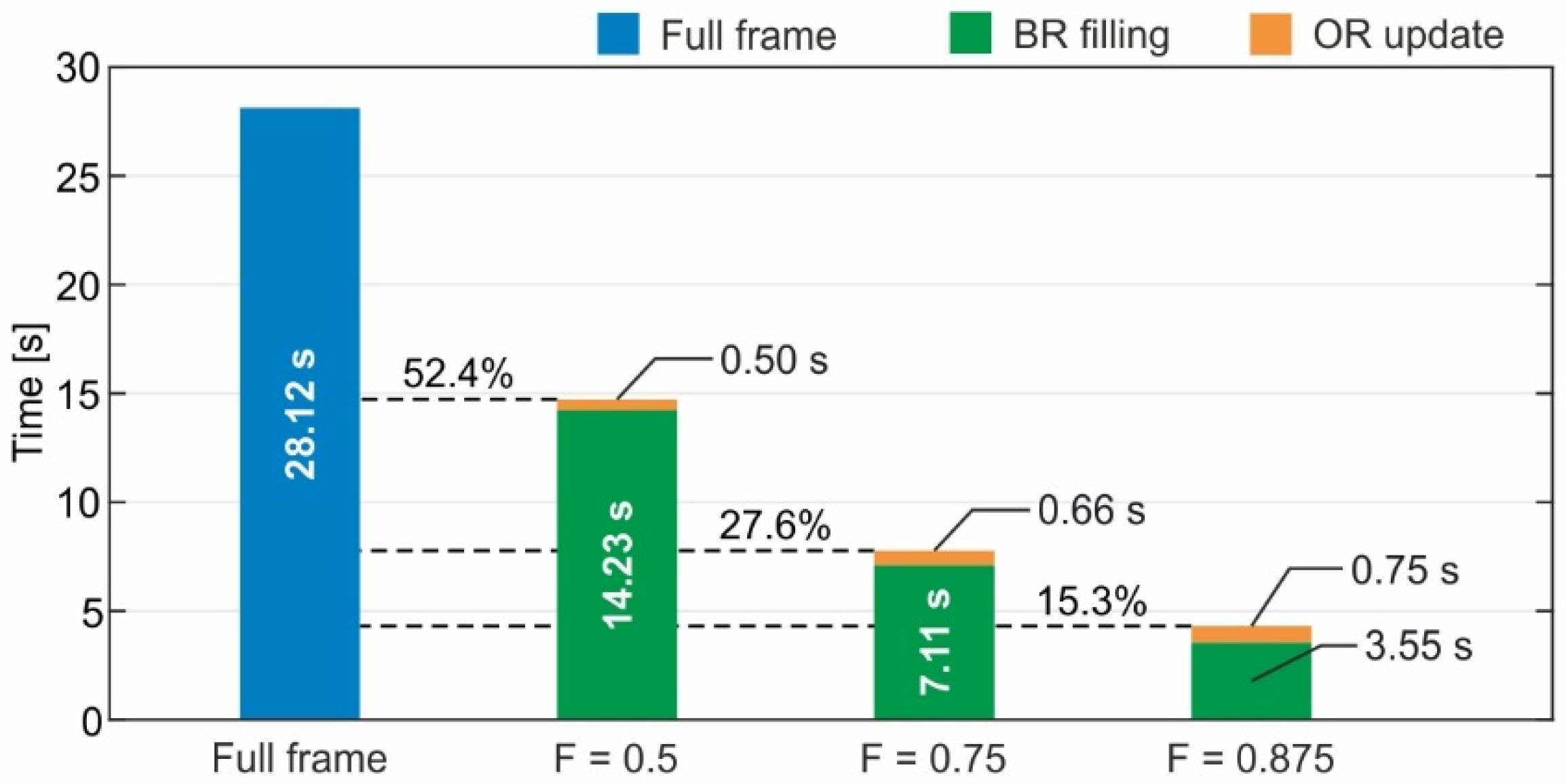
The last numerical test compared the calculation time of the holographic frame with the proposed update algorithm and the full calculation of new holographic frames. The generated CGHs had the same parameters as in the accuracy test. As a test object, a large point cloud made of one million randomly distributed points was used. In the speed test, 100 holographic frames were generated with the update method for three different values of overlap factor
F: 0.5, 0.75, and 0.875 and with the PAS method. For each hologram, calculation time was measured and the average time computed. For the proposed update algorithm, time measurements for reuse of the overlap region and filling of the blank region were made separately. The results are presented in
Figure 7.
The process of the update algorithm changes linearly with the size of the blank region. A-PAS generating hologram data for this area is a major component of calculation time. The time needed to update the overlap region is a small part of total generation time and is proportional to the size of the overlap region.
6. Numerical and Optical Reconstruction of Updated CGH
In this section, object reconstructions from CGHs calculated with hologram update method are carried out. Our research is based on the geometry of wide-angle near-eye holographic displays. Thus, parameters for optical and numerical experiments were selected for fulfilling continuous viewpoint change in a wide-angle viewing configuration. Moreover, in both experiments the same viewpoint elliptical trajectory around the 3D scene was investigated. During the full turn, the hologram displacement in a single step, given in overlap factor F, varies from 0.4 to 0.6. The test object was a 3D point cloud representing a statue of Neptune, consisting of about 4 million points and a point density of 5.5 points/mm2. The object’s lateral dimensions and location were selected to cover 35° of FoV.
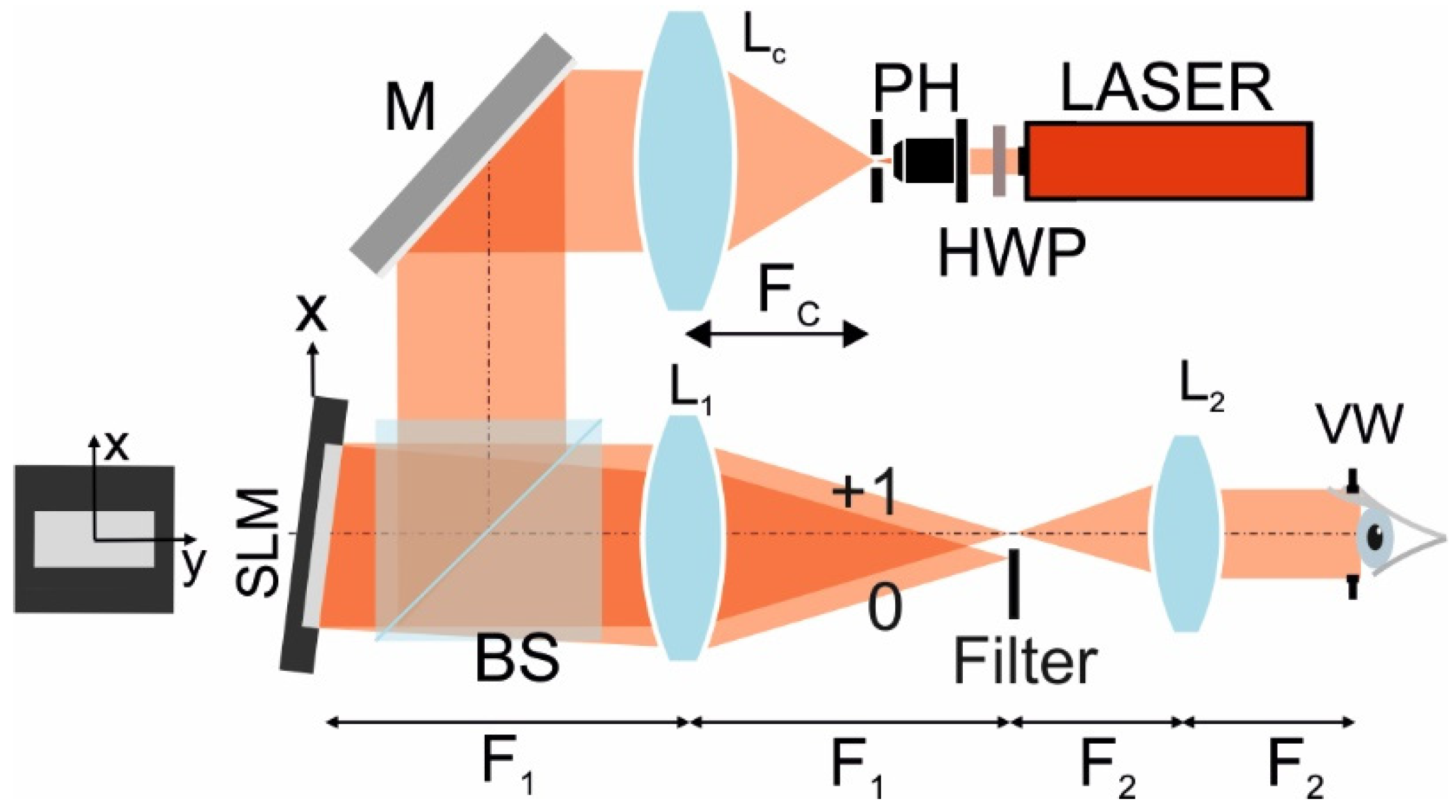
Experimental verification of the hologram update method is realized in the near-eye holographic display presented in
Figure 8. A helium–neon red laser (
λ = 632.8 nm) was employed as the illumination source. The beam passed through a half-wave plate HWP, which matched the polarization state of the illumination and the liquid crystals on SLM. Next, plane wave illumination was formed with an assembly composed of microscopic objective (MO), pinhole (PH), and collimating lens Lc (
Fc = 300 mm). Mirror M and beam-splitting cube BS redirected the beam to the 4K SLM (HoloEye Gaea 2.0, pixel pitch 3.74 µm). SLM was addressed with the phase CGH with added spatial carrier frequency, which separated zero from information order. As depicted in
Figure 8, the SLM was tilted, and information order propagated along the optical axis. Next, the 4F imaging system, composed of lenses L1 and L2, demagnified the pixel pitch of the SLM. In our implementation, magnification was equal to 0.165. As a result, pixel size at the viewing window VW plane was 0.62 µm, which enabled an
FoV ≈ 61°. However, in the experimental setup, the viewing angle was limited by the diameter of lens L2, which allowed an
FoV ≈ 36°. Hence, the point cloud was matched to the dimensions 414 mm width, 504 mm height, and 222 mm depth in order to fit into the FoV of the optical system.
For the optical experiment, CGHs corresponding to the continuous change of the viewpoint around the object were calculated with the proposed hologram update method, and the generated information was loaded in the SLM as described previously. However, as the viewpoint moved, the hidden areas of the statue changed. Thus, occlusion culling of those unseen regions was necessary for proper depth perception. The unwanted regions were removed using the occlusion culling based-PAS algorithm from [
23]. As described in
Section 3, occlusion culling using based-A-PAS can remove unwanted back points when selecting proper
Ns and
q. The choice of PAS parameters depends on the point cloud density. In our case, the 3D point cloud of Neptune had a density of 5.5 points per millimeter square. With this density and the selected geometry of the holographic display, the angular spacing of the Neptune cloud was obtained as around 0.035°. This criterion defines the maximum size of the extended segment as 1573 pixels [
23]. Thus, for the CGH calculations of this work,
Ns = 512 and
q = 3 were used. The selected parameters allowed for fast calculations, high accuracy, and robust occlusion culling of unwanted areas.
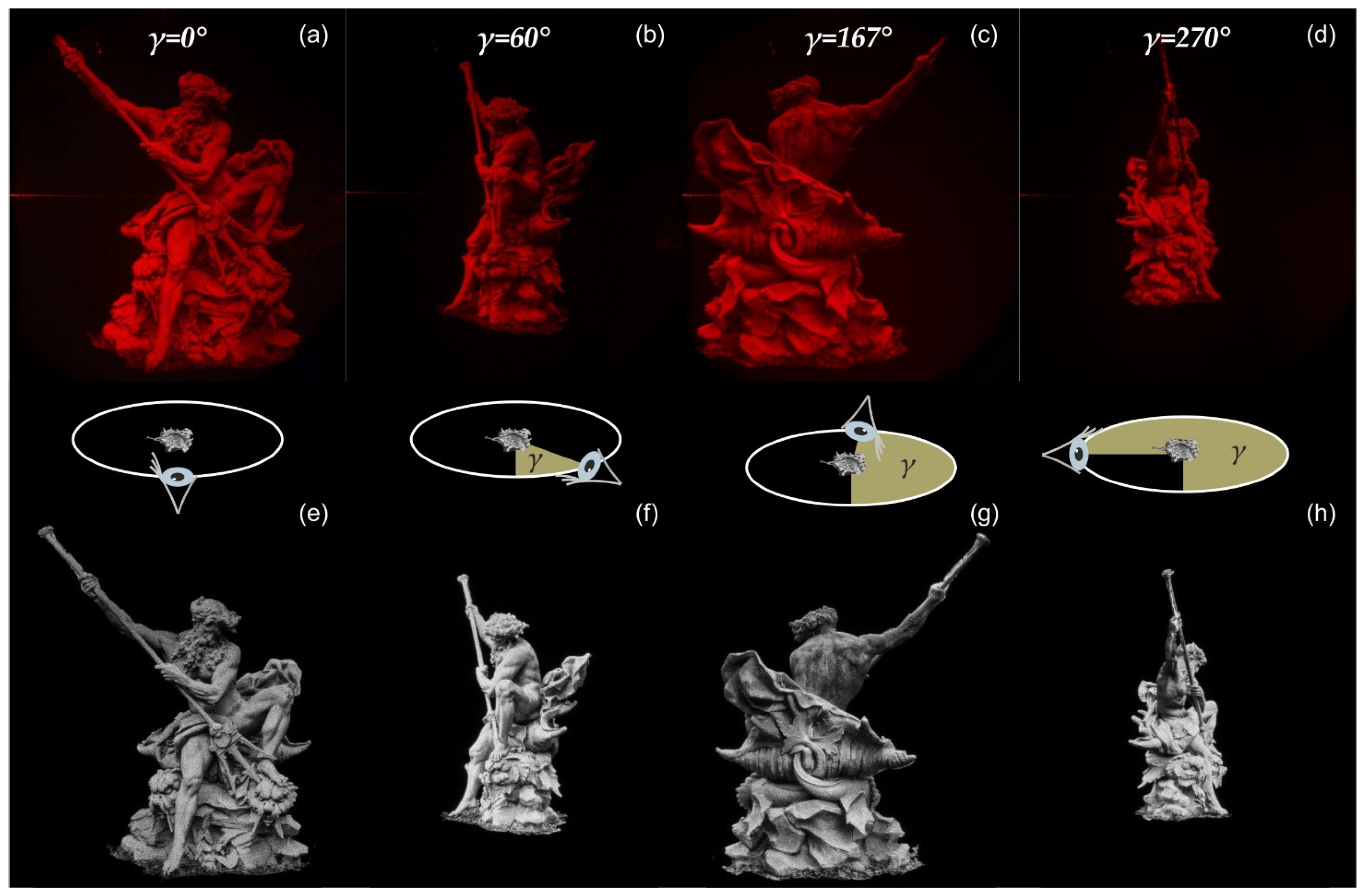
The holographic scene simulated eye movement on the horizontal plane around the object along an elliptical trajectory. The motion was counterclockwise, with the eye always facing toward the object. The minor ellipse axis had 1600 mm, while the major had 2400 mm. As a result, the minimum and maximum distance from the object to the hologram was 800 mm and 1200 mm, respectively. For the nearest viewpoint position, the object was seen at angle 35°, while for the farthermost position, the object was seen at angle 23°.
Video S1 presents the optical reconstruction of the simulated scene made of 4950 holographic frames for a full turn. The top row of
Figure 9 shows example views of the reconstructed holograms for selected object observation points. The middle row of this figure depicts the position of the viewer within the ellipse.
Numerical reconstructions of the same viewpoints are presented to illustrate the imaging quality without experimental constraints in the bottom row of
Figure 9. The numerical reconstruction of the updated holograms was carried out with the Compact Space-Bandwidth AS (AS-CSW) method [
31]. However, for the investigated wide-angle CGHs, accurate reconstruction required a huge amount of zero padding, dramatically increasing the computational load. Thus, in numerical reconstructions, the pixel pitch was increased to Δ = 1 µm, which gives an
FoV ≈ 37°. Due to the change in pixel size, the computational parameters of A-PAS must be changed as well in order to meet the occlusion criterion. For the used pixel pitch, the maximum size of the extended segment was 975 pixels. Then, parameters
Ns = 512 and
q = 1 were selected for fast processing of the CGHs. With the new parameters for the PAS method, a new set of CGHs representing the same motion around the object were calculated. In
Figure 9e–h, reconstructions of viewpoints are presented which are the same as the optical reconstruction. Moreover, full numerical movement around Neptune was made with 3070 holographic frames, and is shown in
Video S2.
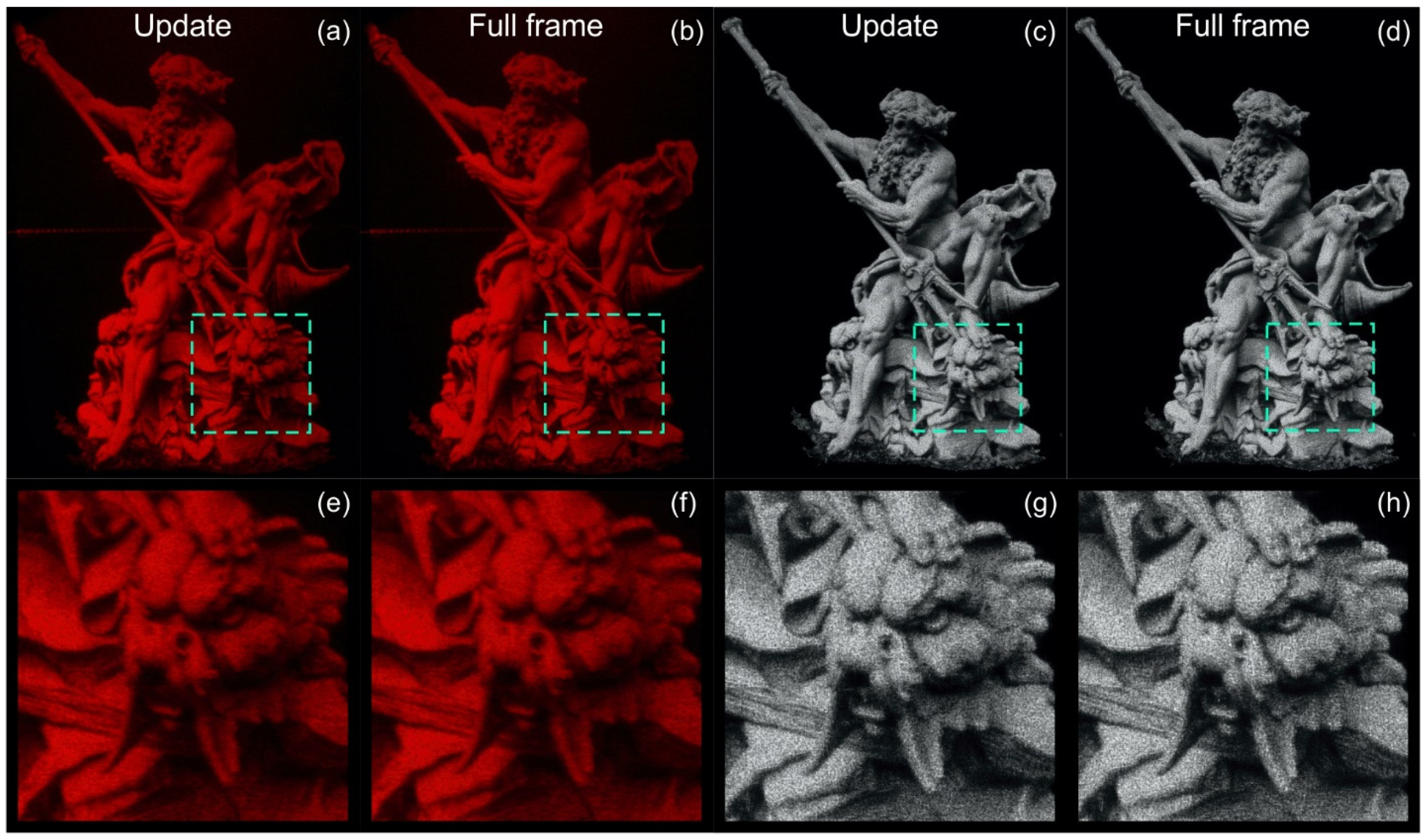
Finally, a comparison between the proposed update method and the full-frame calculation for the Neptune cloud was carried out. The comparison was performed for the same elliptical trajectory and overlap coefficient variation as used in the experiment shown in
Figure 9.
Figure 10a shows the optical reconstruction obtained by using the proposed update method after viewing rotation by an angle of 340°, while
Figure 10b presents the result of full frame PAS algorithm for the same viewpoint. To show the different results of the update process, this part of the experiment employed clockwise rotation of viewpoint. The numerical reconstructions calculated for the same viewpoint location are displayed in
Figure 10c,d for the hologram update method and the full PAS calculations, respectively. In
Figure 10e–h, zooms of the sea dragon face are depicted. Notably, the experimental and numerical comparisons present a high level of similarity between the images rendered with the hologram update method and the PAS. The zooms illustrate the fine details of the reconstructed object, with both methods showing that our approach enables distortion-free content.
7. Conclusions
In this work, we propose a hologram update method for wide viewing angle holographic near-eye display, where the hologram plane is related to the eye position. Our solution addresses small viewpoint changes where two consecutive holograms have an overlapping region. The overlapping region is reused in the calculation framework of the updated hologram view. The update algorithm has two main components, which consist of transferring data from the overlapping regions and calculation of new information for the blank region. The transfer of overlapping regions is calculated by the classical AS method and approximate tilting, which is realized with an optimized frequency shift operation. It is worth noting that for the case of wide-angle holograms, this approximate tilt introduces minimal errors. New holographic information is introduced via the PAS method, which is an efficient tool for calculation of wide-angle CGH. The whole scheme enables significant acceleration, improving the calculation time of the final hologram. Numerical tests confirm the high accuracy of updated holograms for different sizes of overlap region. Moreover, it is shown that degradation of image quality over a large number of hologram update cycles is neglectable. Thus, the proposed method allows for quick generation of a sequence of wide-angle CGHs for continuous movement around 3D objects.
Speed testing demonstrates that the computation time of this hologram update method is a linear function that mainly depends on the dimensions of the non-overlapping area, which must be newly computed using the PAS method. For example, for a 50% overlapping area size, the computation time is improved by a factor of two. Thus, the computations related to the overlapping area can be considered as negligible. The hologram update method is demonstrated for a display with an FoV of 62° and an average image size of approximately one meter, and numerical and optical reconstructions where the continuous movement of an observer on an elliptical trajectory around an object are carried out. The employed object, a dense point cloud of 4 million points representing a statue of Neptune, contains a large variety of features for each viewpoint. The obtained reconstructions of the 3D scene show that the proposed method provides continuous viewpoint change with high quality images, and is comparable with full frame CGH calculations.


 ,
, 