
Innovative Collaborative Method for Interaction between a Human Operator and Robotic Manipulator Using Pointing Gestures


Abstract
:1. Introduction
2. Related Work
3. Our Approach
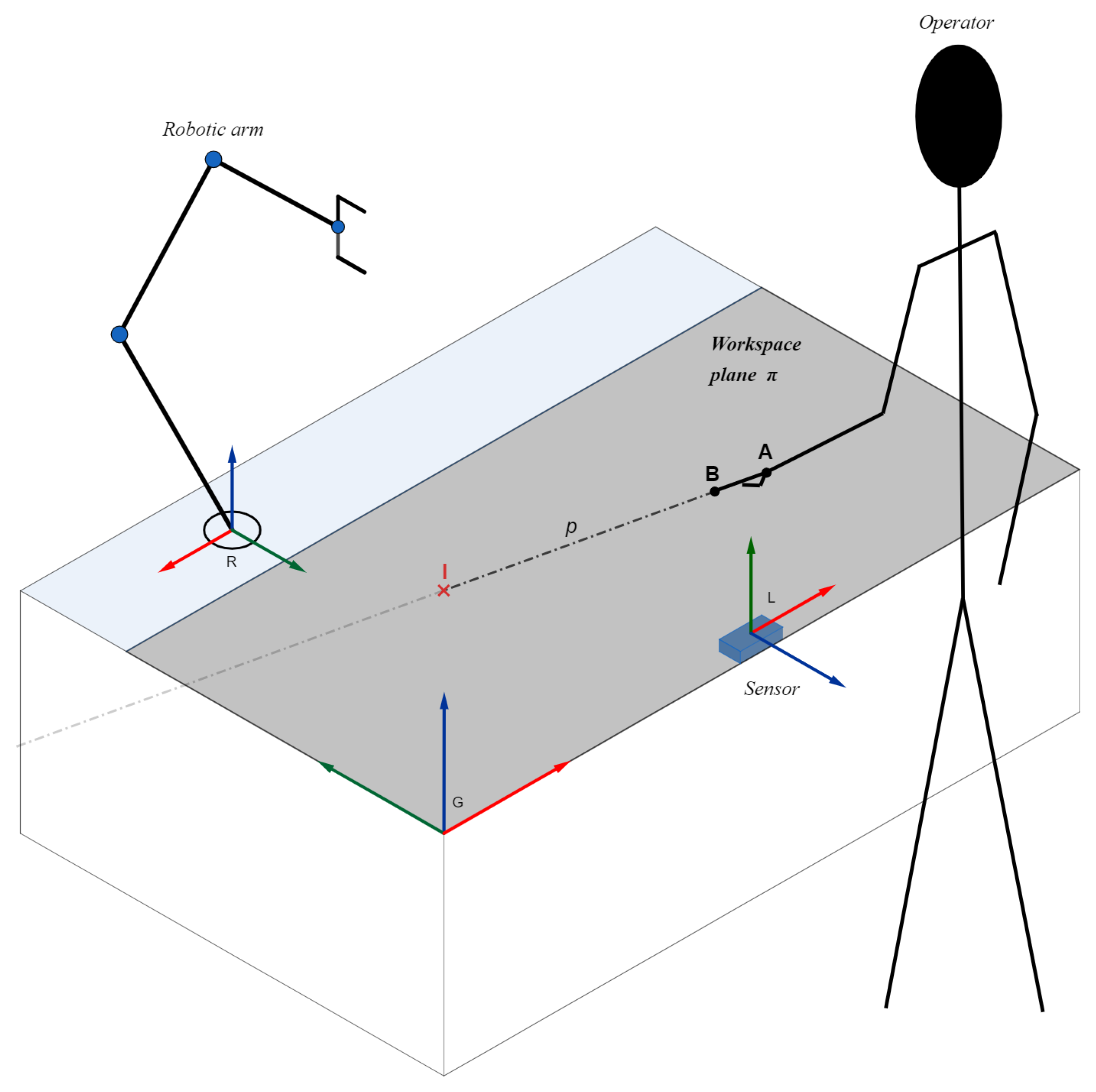
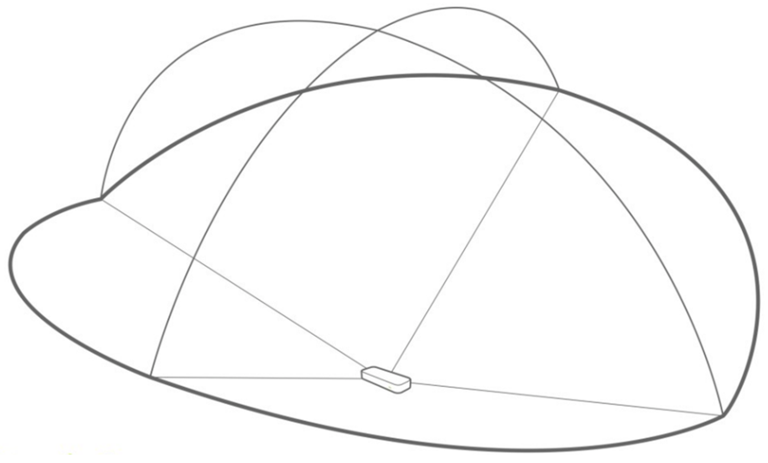
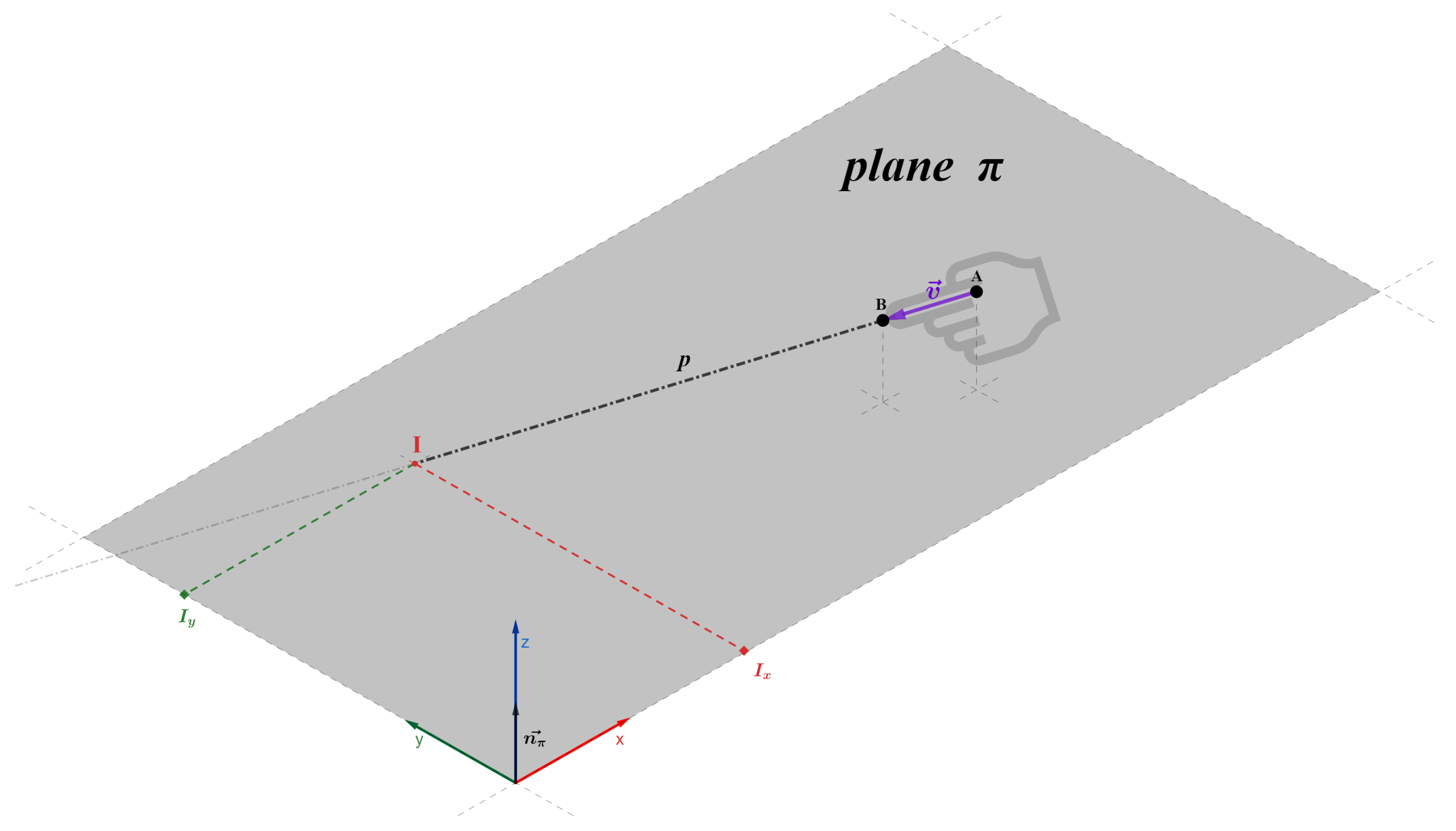
- Every pair of two joints of a human sensed by a robot form a line.
- Every line defined by the first law intersects with the robot’s environment in one or two places.
- Every intersection defined by the second law is a potential navigation target or a potential object of reference for the robot.
- Choosing suitable technology and a method of detecting the position and orientation of human joints.
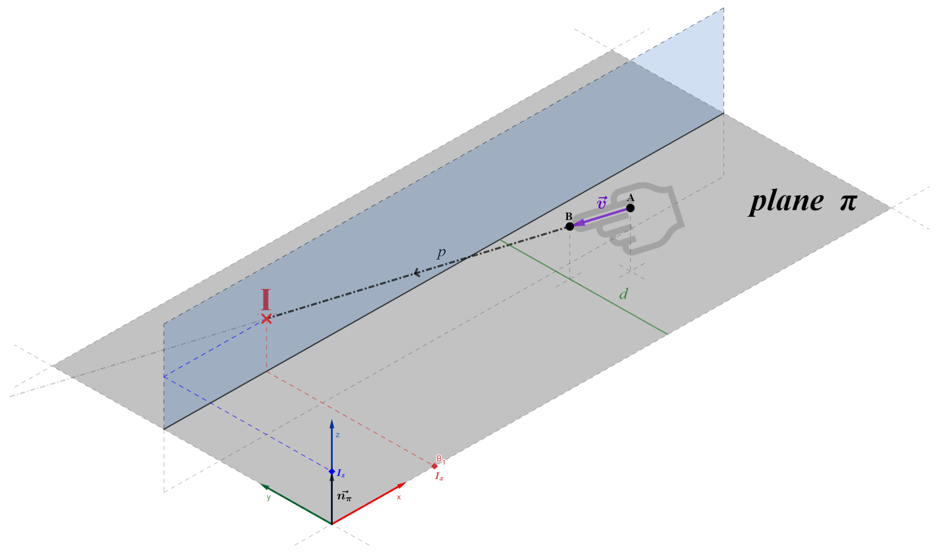
- Calculating the exact position of the intersection between the formed line and the environment surface.
- Selecting the pair of joints to form and calculate the line following the first two principles of linear HRI.
4. The Human Body Tracking and Joint Recognition
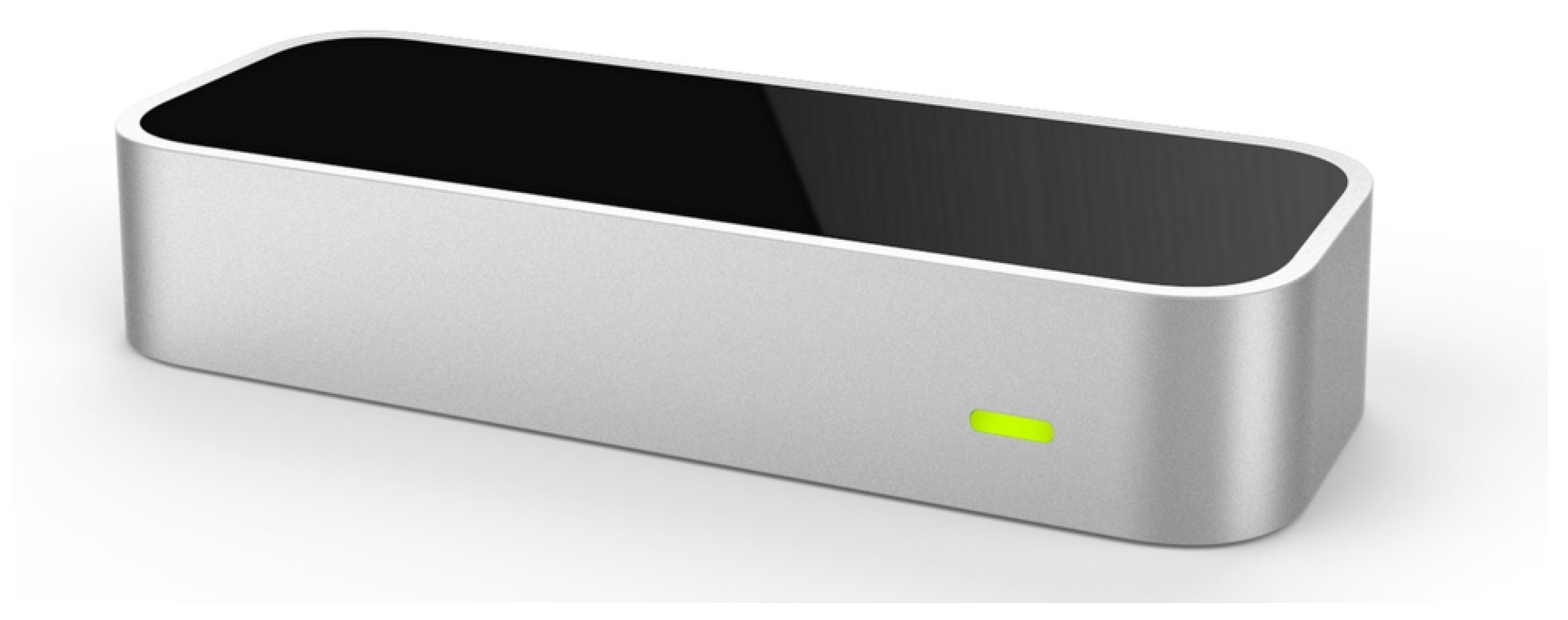
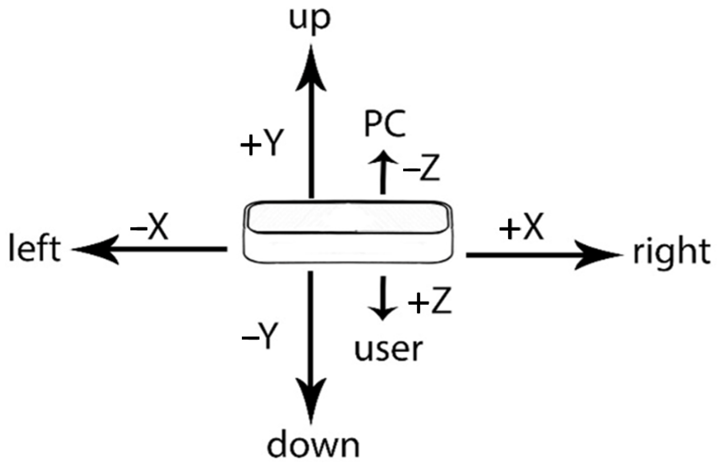
Sensor Choice for the Proposed Concept
5. Method Design
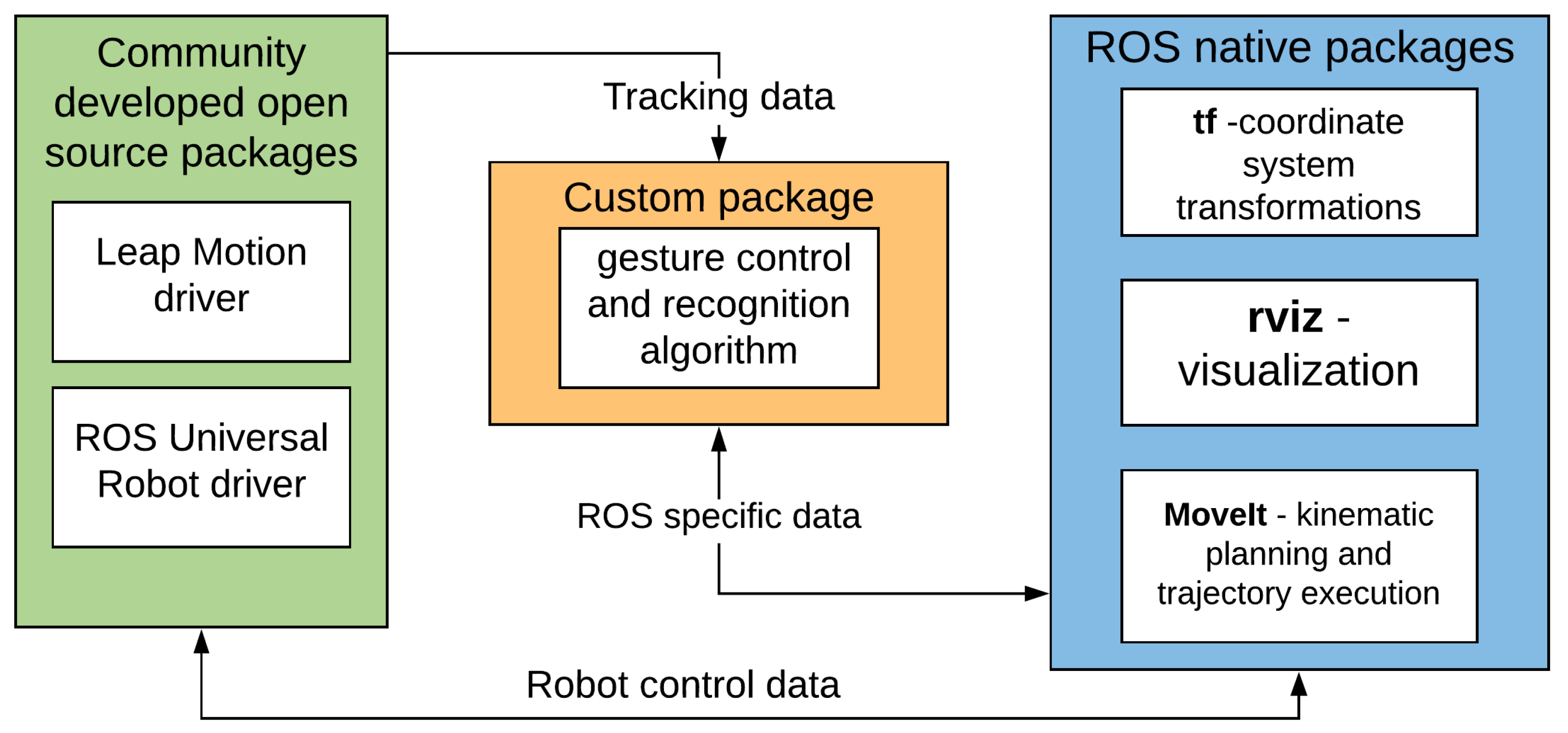
6. Method Implementation
7. Experimental Evaluation
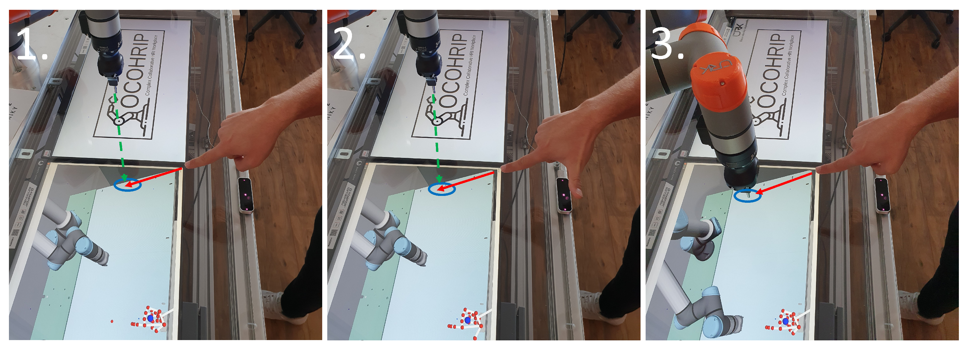
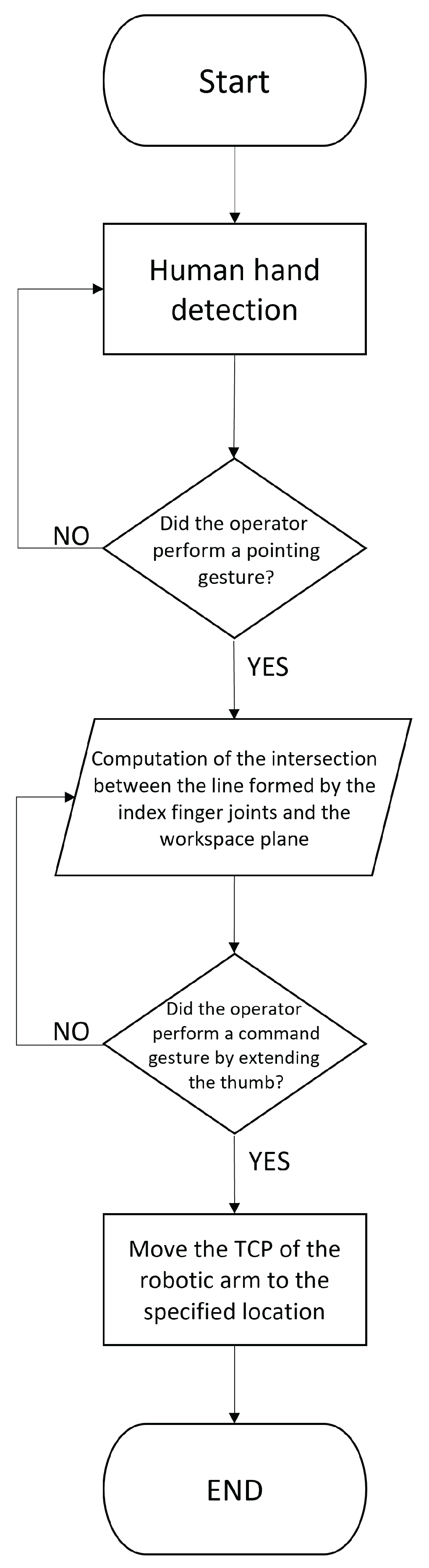
- The operator’s hand is calibrated for optimal gesture recognition.
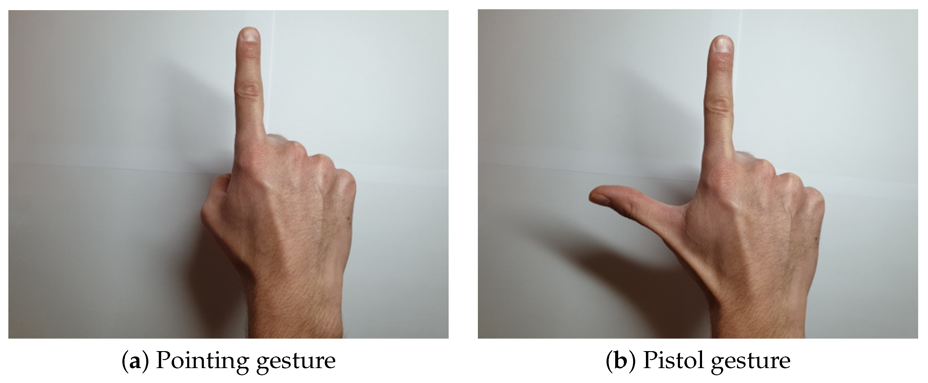
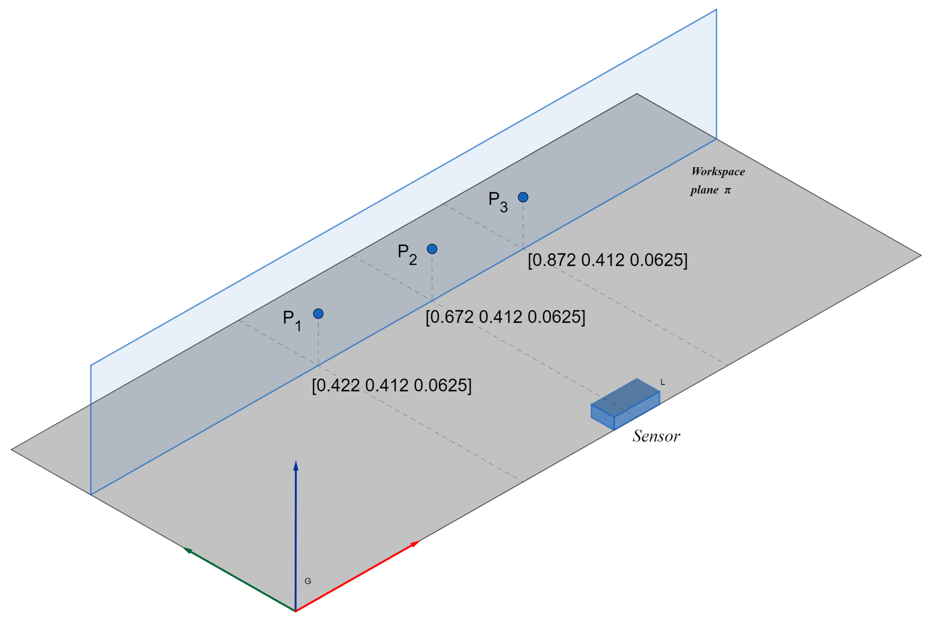
- The operator points to the first point, and when he is satisfied with his estimation, he performs a command gesture.
- When the operator performs a command gesture, the spatial data are logged, and the robot’s TCP moves to the pointed location.
8. Results
9. Discussion
10. Conclusions
Author Contributions
Funding
Data Availability Statement
Conflicts of Interest
References
- Tang, N. Securing the Future of German Manufacturing Industry Recommendations for Implementing the Strategic Initiative INDUSTRIE 4.0 Final Report of the Industrie 4.0 Working Group; Acatech: Munich, Germany, 2013. [Google Scholar]
- Matheson, E.; Minto, R.; Zampieri, E.G.G.; Faccio, M.; Rosati, G. Human—Robot Collaboration in Manufacturing Applications: A Review. Robotics 2019, 8, 100. [Google Scholar] [CrossRef] [Green Version]
- Gualtieri, L.; Rauch, E.; Vidoni, R. Emerging research fields in safety and ergonomics in industrial collaborative robotics: A systematic literature review. Robot. Comput.-Integr. Manuf. 2021, 67, 101998. [Google Scholar] [CrossRef]
- Thoben, K.; Wiesner, S.; Wuest, T. “Industrie 4.0” and Smart Manufacturing—A Review of Research Issues and Application Examples. Int. J. Autom. Technol. 2017, 11, 4–16. [Google Scholar] [CrossRef] [Green Version]
- Tang, G.; Webb, P. The Design and Evaluation of an Ergonomic Contactless Gesture Control System for Industrial Robots. J. Robot. 2018, 2018, 9791286. [Google Scholar] [CrossRef] [Green Version]
- Tölgyessy, M.; Dekan, M.; Duchoň, F.; Rodina, J.; Hubinský, P.; Chovanec, L. Foundations of Visual Linear Human–Robot Interaction via Pointing Gesture Navigation. Int. J. Soc. Robot. 2017, 9, 509–523. [Google Scholar] [CrossRef]
- Cho, H.; Chung, W. Preliminary research on robust leg-tracking indoor mobile robots by combining the Kinect and the laser range finder information. In Proceedings of the 12th International Conference on Ubiquitous Robots and Ambient Intelligence (URAI), Goyangi, Korea, 28–30 October 2015. [Google Scholar] [CrossRef]
- Chen, M.; Liu, C.; Du, G. A human—Robot interface for mobile manipulator. Intell. Serv. Robot. 2018, 11, 269–278. [Google Scholar] [CrossRef]
- Burger, B.; Ferrané, I.; Lerasle, F.; Infantes, G. Two-handed gesture recognition and fusion with speech to command a robot. Auton. Robot. 2012, 32, 129–147. [Google Scholar] [CrossRef]
- Valner, R.; Kruusamäe, K.; Pryor, M. TeMoto: Intuitive Multi-Range Telerobotic System with Natural Gestural and Verbal Instruction Interface. Robotics 2018, 7, 9. [Google Scholar] [CrossRef] [Green Version]
- Hernoux, F.; Béarée, R.; Gibaru, O. Investigation of dynamic 3D hand motion reproduction by a robot using a Leap Motion. In Proceedings of the 2015 Virtual Reality International Conference. Association for Computing Machinery, VRIC ’15, Laval, France, 8–10 April 2015; pp. 1–10. [Google Scholar] [CrossRef]
- Du, G.; Zhang, P.; Liu, X. Markerless Human–Manipulator Interface Using Leap Motion With Interval Kalman Filter and Improved Particle Filter. IEEE Trans. Ind. Inform. 2016, 12, 694–704. [Google Scholar] [CrossRef]
- Kruse, D.; Wen, J.T.; Radke, R.J. A Sensor-Based Dual-Arm Tele-Robotic System. IEEE Trans. Autom. Sci. Eng. 2015, 12, 4–18. [Google Scholar] [CrossRef]
- Bassily, D.; Georgoulas, C.; Guettler, J.; Linner, T.; Bock, T. Intuitive and Adaptive Robotic Arm Manipulation using the Leap Motion Controller. In Proceedings of the ISR/Robotik 2014: 41st International Symposium on Robotics, Munich, Germany, 2–3 June 2014. [Google Scholar]
- Pititeeraphab, Y.; Choitkunnan, P.; Thongpance, N.; Kullathum, K.; Pintavirooj, C. Robot-arm control system using LEAP motion controller. In Proceedings of the 2016 International Conference on Biomedical Engineering (BME-HUST), Hanoi, Vietnam, 5–6 October 2016; pp. 109–112. [Google Scholar] [CrossRef]
- Chen, C.; Chen, L.; Zhou, X.; Yan, W. Controlling a robot using leap motion. In Proceedings of the 2017 2nd International Conference on Robotics and Automation Engineering (ICRAE), Shanghai, China, 29–31 December 2017; pp. 48–51. [Google Scholar] [CrossRef]
- Chen, S.; Ma, H.; Yang, C.; Fu, M. Hand Gesture Based Robot Control System Using Leap Motion. In Proceedings of the Intelligent Robotics and Applications, Portsmouth, UK, 24–27 August 2015; Lecture Notes in Computer Science. Liu, H., Kubota, N., Zhu, X., Dillmann, R., Zhou, D., Eds.; Springer International Publishing: Berlin/Heidelberg, Germany, 2015; pp. 581–591. [Google Scholar] [CrossRef]
- Nogueira, R.; Reis, J.; Pinto, R.; Gonçalves, G. Self-adaptive Cobots in Cyber-Physical Production Systems. In Proceedings of the 2019 24th IEEE International Conference on Emerging Technologies and Factory Automation (ETFA), Zaragoza, Spain, 10–13 September 2019; pp. 521–528. [Google Scholar] [CrossRef] [Green Version]
- Cueva, C.W.F.; Torres, S.H.M.; Kern, M.J. 7 DOF industrial robot controlled by hand gestures using microsoft kinect v2. In Proceedings of the 2017 IEEE 3rd Colombian Conference on Automatic Control (CCAC), Cartagena, Colombia, 18–20 October 2017; pp. 1–6. [Google Scholar] [CrossRef]
- Kaczmarek, W.; Panasiuk, J.; Borys, S.; Banach, P. Industrial Robot Control by Means of Gestures and Voice Commands in Off-Line and On-Line Mode. Sensors 2020, 20, 6358. [Google Scholar] [CrossRef]
- Zhang, X.; Zhang, R.; Chen, L.; Zhang, X. Natural Gesture Control of a Delta Robot Using Leap Motion. J. Phys. 2019, 1187, 032042. [Google Scholar] [CrossRef]
- Cipolla, R.; Hollinghurst, N. A Human–Robot Interface using Pointing with Uncalibrated Stereo Vision. In Computer Vision for Human-Machine Interaction; Pentland, A., Cipolla, R., Eds.; Cambridge University Press: Cambridge, UK, 1998; pp. 97–110. [Google Scholar] [CrossRef]
- Gunawardane, P.; Medagedara, N.T.; Madusanka, B.; Wijesinghe, S. The development of a Gesture Controlled Soft Robot gripping mechanism. In Proceedings of the 2016 IEEE International Conference on Information and Automation for Sustainability (ICIAfS), Galle, Sri Lanka, 16–19 December 2016; pp. 1–6. [Google Scholar] [CrossRef]
- Devine, S.; Rafferty, K.; Ferguson, S. Real time robotic arm control using hand gestures with multiple end effectors. In Proceedings of the 2016 UKACC 11th International Conference on Control (CONTROL), Belfast, UK, 31 August–2 September 2016; pp. 1–5. [Google Scholar] [CrossRef]
- Li, C.; Fahmy, A.; Sienz, J. Development of a Neural Network-Based Control System for the DLR-HIT II Robot Hand Using Leap Motion. IEEE Access 2019, 7, 136914–136923. [Google Scholar] [CrossRef]
- Razjigaev, A.; Crawford, R.; Roberts, J.; Wu, L. Teleoperation of a concentric tube robot through hand gesture visual tracking. In Proceedings of the 2017 IEEE International Conference on Robotics and Biomimetics (ROBIO), Macau, Macao, 5–8 December 2017; pp. 1175–1180. [Google Scholar] [CrossRef] [Green Version]
- Sarkar, A.; Patel, K.A.; Ganesh Ram, R.; Capoor, G.K. Gesture control of drone using a motion controller. In Proceedings of the 2016 International Conference on Industrial Informatics and Computer Systems (CIICS), Sharjah, United Arab Emirates, 13–15 March 2016; pp. 1–5. [Google Scholar] [CrossRef]
- Hu, B.; Wang, J. Deep Learning Based Hand Gesture Recognition and UAV Flight Controls. In Proceedings of the 2018 24th International Conference on Automation and Computing (ICAC), Newcastle Upon Tyne, UK, 6–7 September 2018; pp. 1–6. [Google Scholar] [CrossRef]
- Yu, N.; Xu, C.; Wang, K.; Yang, Z.; Liu, J. Gesture-based telemanipulation of a humanoid robot for home service tasks. In Proceedings of the 2015 IEEE International Conference on Cyber Technology in Automation, Control, and Intelligent Systems (CYBER), Shenyang, China, 8–12 June 2015; pp. 1923–1927. [Google Scholar] [CrossRef]
- Cheng, L.; Sun, Q.; Su, H.; Cong, Y.; Zhao, S. Design and implementation of human–robot interactive demonstration system based on Kinect. In Proceedings of the 2012 24th Chinese Control and Decision Conference (CCDC), Taiyuan, China, 23–25 May 2012; pp. 971–975. [Google Scholar] [CrossRef]
- Liu, Y.; Zhang, Y. Toward Welding Robot With Human Knowledge: A Remotely-Controlled Approach. IEEE Trans. Autom. Sci. Eng. 2015, 12, 769–774. [Google Scholar] [CrossRef]
- Yang, C.; Zeng, C.; Liang, P.; Li, Z.; Li, R.; Su, C.Y. Interface Design of a Physical Human–Robot Interaction System for Human Impedance Adaptive Skill Transfer. IEEE Trans. Autom. Sci. Eng. 2018, 15, 329–340. [Google Scholar] [CrossRef]
- Krupke, D.; Steinicke, F.; Lubos, P.; Jonetzko, Y.; Görner, M.; Zhang, J. Comparison of Multimodal Heading and Pointing Gestures for Co-Located Mixed Reality Human–Robot Interaction. In Proceedings of the 2018 IEEE/RSJ International Conference on Intelligent Robots and Systems (IROS), Madrid, Spain, 1–5 October 2018; pp. 1–9. [Google Scholar] [CrossRef]
- Zhou, H.; Hu, H. Human motion tracking for rehabilitation—A survey. Biomed. Signal Process. Control 2008, 3, 1–18. [Google Scholar] [CrossRef]
- Vardhan, D.; Prasad, P.P. Hand Gesture Recognition Application for Physically Disabled People. Int. J. Sci. Res. 2014, 3, 765–769. [Google Scholar]
- Parvini, F.; McLeod, D.; Shahabi, C.; Navai, B.; Zali, B.; Ghandeharizadeh, S. An Approach to Glove-Based Gesture Recognition. In Proceedings of the Human-Computer Interaction. Novel Interaction Methods and Techniques, San Diego, CA, USA, 19–24 July 2009; Lecture Notes in Computer Science. Jacko, J.A., Ed.; Springer: Berlin/Heidelberg, Germany, 2009; pp. 236–245. [Google Scholar] [CrossRef] [Green Version]
- Allevard, T.; Benoit, E.; Foulloy, L. Fuzzy Glove For Gesture Recognition. In Proceedings of the 17th IMEKO World Congress, Dubrovnik, Croatia, 22–28 June 2003; pp. 2026–2031. [Google Scholar]
- Ghunawat, M.R. Multi-point Gesture Recognition Using LED Gloves For Interactive HCI. Int. J. Comput. Sci. Inf. Technol. 2014, 5, 6768–6773. [Google Scholar]
- Ganzeboom, M. How Hand Gestures Are Recognized Using a Dataglove. 2009. Available online: https://www.researchgate.net/publication/228702251_How_hand_gestures_are_recognized_using_a_dataglove (accessed on 19 December 2021).
- Shotton, J.; Girshick, R.; Fitzgibbon, A.; Sharp, T.; Cook, M.; Finocchio, M.; Moore, R.; Kohli, P.; Criminisi, A.; Kipman, A.; et al. Efficient Human Pose Estimation from Single Depth Images. IEEE Trans. Pattern Anal. Mach. Intell. 2013, 35, 2821–2840. [Google Scholar] [CrossRef]
- Guzsvinecz, T.; Szucs, V.; Sik-Lanyi, C. Suitability of the Kinect Sensor and Leap Motion Controller—A Literature Review. Sensors 2019, 19, 1072. [Google Scholar] [CrossRef] [Green Version]
- Vysocký, A.; Grushko, S.; Oščádal, P.; Kot, T.; Babjak, J.; Jánoš, R.; Sukop, M.; Bobovský, Z. Analysis of Precision and Stability of Hand Tracking with Leap Motion Sensor. Sensors 2020, 20, 4088. [Google Scholar] [CrossRef]
- Guna, J.; Jakus, G.; Pogačnik, M.; Tomažič, S.; Sodnik, J. An Analysis of the Precision and Reliability of the Leap Motion Sensor and Its Suitability for Static and Dynamic Tracking. Sensors 2014, 14, 3702–3720. [Google Scholar] [CrossRef] [Green Version]


| Lit. | Robotic System | Sensor | Visual Tracking | Weareables | Tele- Operation | Workspace Interaction | Pointing to Objects |
|---|---|---|---|---|---|---|---|
| [11] | UR10 | Leap Motion | Yes | - | Yes | - | - |
| [17] | UR10 simulation | Leap Motion | Yes | - | Yes | - | - |
| [16] | EPSON SCARA LS3-401x | Leap Motion | Yes | - | Yes | - | - |
| [21] | Custom Delta architecture | Leap Motion | Yes | - | Yes | - | - |
| [5] | UR5 | Leap Motion | Yes | - | Yes | - | - |
| [12] | GOOGOL GRB3016 | Leap Motion | Yes | - | Yes | - | - |
| [31] | UR5 | Leap Motion | Yes | - | Yes | - | - |
| [20] | ABB IRB120 | Kinect V2 | Yes | - | Yes | - | - |
| [32] | Baxter | MYO Armband | - | Yes | Yes | Yes | - |
| [33] | UR5 | Microsoft HoloLens | Yes | Yes | Yes | Yes | Yes |
| [19] | Custom 7DOF robot | Kinect V2 | Yes | - | Yes | - | - |
| [18] | UR5 | Kinect V2 | Yes | - | Yes | - | - |
| [13] | Motoman SDA 10 | Kinect V1 | Yes | - | Yes | - | - |
| [22] | Scorbot ER-7 | Stereo CCD cameras | Yes | - | Yes | Yes | Yes |
| Target Marker No. | 1st. Variant (mm) | 2nd. Variant (mm) |
|---|---|---|
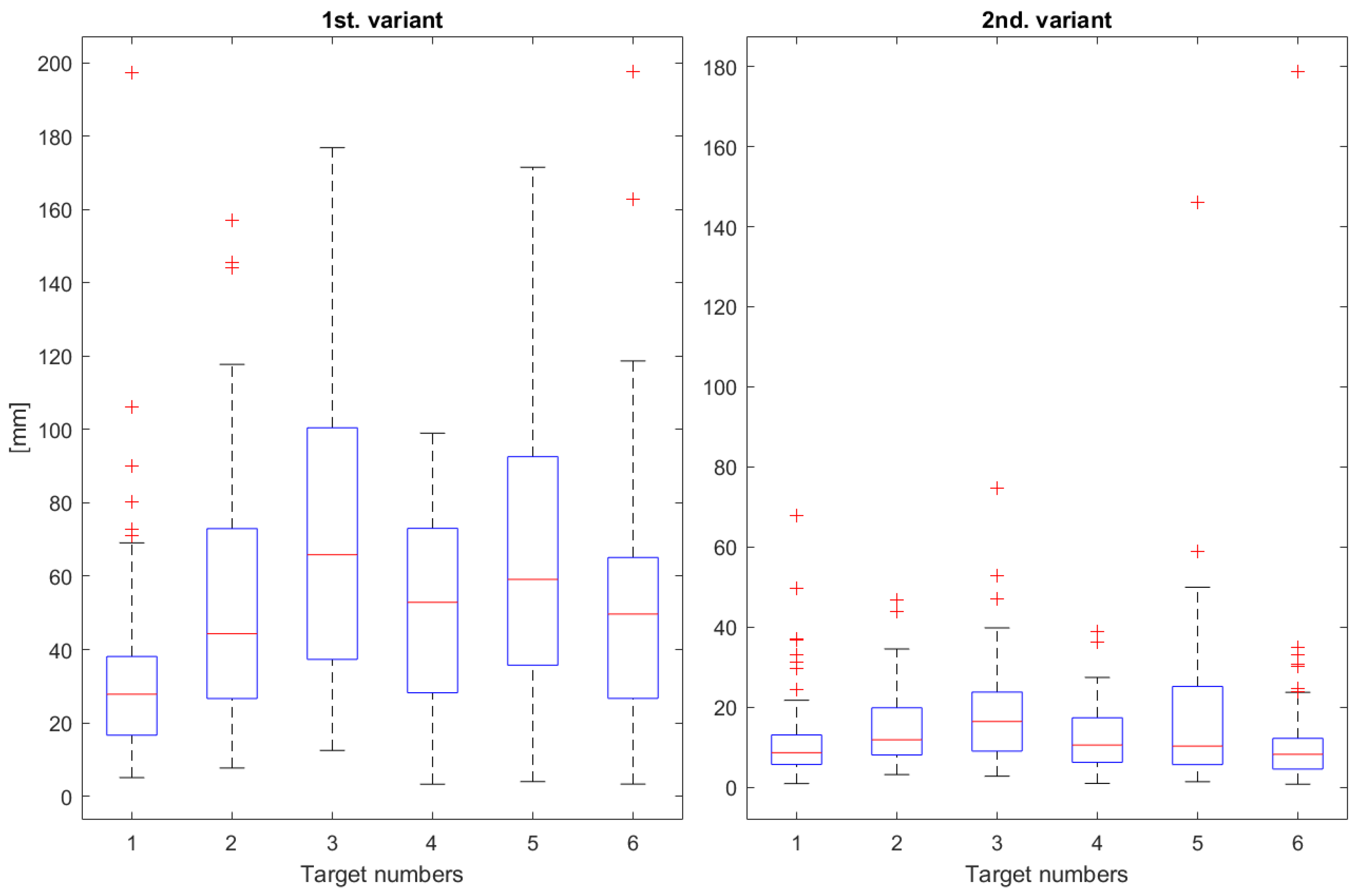
| 1 | 33.42 | 12.16 |
| 2 | 54.18 | 14.81 |
| 3 | 70.71 | 18.68 |
| 4 | 50.88 | 12.60 |
| 5 | 63.99 | 17.64 |
| 6 | 51.45 | 12.54 |
| overall | 54.11 | 14.74 |
| Target Marker No. | 1st. Variant (mm) | 2nd. Variant (mm) |
|---|---|---|
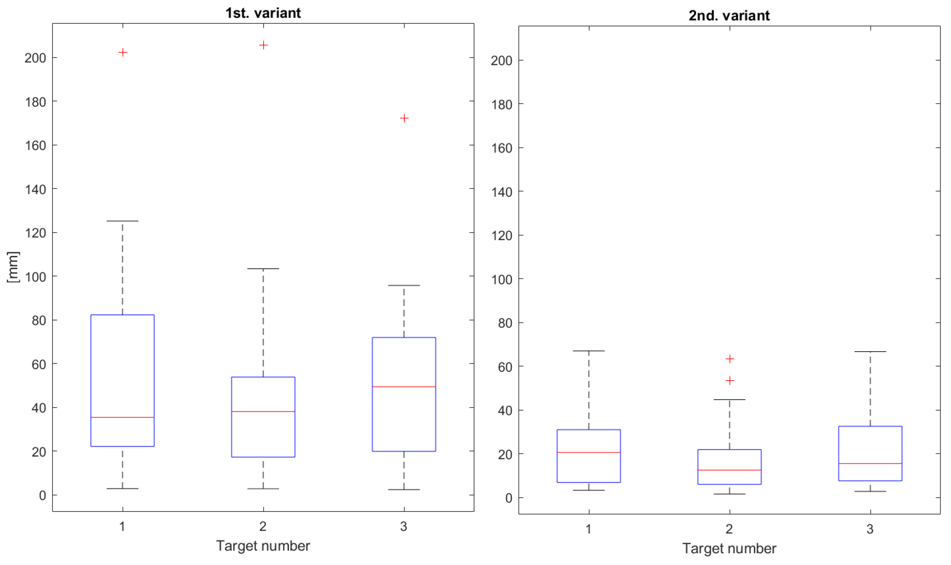
| 1 | 49.77 | 21.17 |
| 2 | 40.56 | 15.62 |
| 3 | 47.25 | 20.21 |
| overall | 45.86 | 19.0 |
| 1st. Variant (mm) | 2nd. Variant (mm) | |||
|---|---|---|---|---|
| x Axis | y Axis | x Axis | y Axis | |
| 1 | 22.42 | 35.32 | 4.94 | 14.07 |
| 2 | 50.14 | 36.93 | 13.28 | 8.35 |
| 3 | 26.92 | 65.54 | 11.24 | 17.64 |
| 4 | 20.08 | 44.55 | 4.91 | 13.99 |
| 5 | 44.31 | 52.0 | 15.46 | 22.34 |
| 6 | 38.71 | 43.99 | 9.06 | 22.82 |
| overall | 33.77 | 46.39 | 9.81 | 16.53 |
| 1st. (mm) | 2nd. Variant (mm) | |||
|---|---|---|---|---|
| x Axis | y Axis | x Axis | y Axis | |
| 1 | 46.10 | 37.44 | 14.47 | 20.79 |
| 2 | 27.74 | 40.20 | 5.61 | 17.93 |
| 3 | 32.88 | 43.96 | 12.66 | 19.40 |
| overall | 35.57 | 40.53 | 10.91 | 19.37 |
Publisher’s Note: MDPI stays neutral with regard to jurisdictional claims in published maps and institutional affiliations. |
© 2021 by the authors. Licensee MDPI, Basel, Switzerland. This article is an open access article distributed under the terms and conditions of the Creative Commons Attribution (CC BY) license (https://creativecommons.org/licenses/by/4.0/).
Share and Cite
Čorňák, M.; Tölgyessy, M.; Hubinský, P. Innovative Collaborative Method for Interaction between a Human Operator and Robotic Manipulator Using Pointing Gestures. Appl. Sci. 2022, 12, 258. https://doi.org/10.3390/app12010258
Čorňák M, Tölgyessy M, Hubinský P. Innovative Collaborative Method for Interaction between a Human Operator and Robotic Manipulator Using Pointing Gestures. Applied Sciences. 2022; 12(1):258. https://doi.org/10.3390/app12010258
Chicago/Turabian StyleČorňák, Marek, Michal Tölgyessy, and Peter Hubinský. 2022. "Innovative Collaborative Method for Interaction between a Human Operator and Robotic Manipulator Using Pointing Gestures" Applied Sciences 12, no. 1: 258. https://doi.org/10.3390/app12010258
APA StyleČorňák, M., Tölgyessy, M., & Hubinský, P. (2022). Innovative Collaborative Method for Interaction between a Human Operator and Robotic Manipulator Using Pointing Gestures. Applied Sciences, 12(1), 258. https://doi.org/10.3390/app12010258