Article

Reconstruction of Isolated Moving Objects by Motion-Induced Phase Shift Based on PSP

1
Faculty of Artificial Intelligence in Education, Central China Normal University, Wuhan 430079, China
2
College of Information Science and Engineering, Henan University of Technology, Zhengzhou 450001, China
3
School of Electrical Computer and Telecommunications Engineering, University of Wollongong, Wollongong, NSW 2522, Australia
*
Author to whom correspondence should be addressed.
Appl. Sci. 2022, 12(1), 252; https://doi.org/10.3390/app12010252
Submission received: 25 November 2021 / Revised: 19 December 2021 / Accepted: 24 December 2021 / Published: 28 December 2021

Abstract

:
The reconstruction of moving objects based on phase shifting profilometry has attracted intensive interests. Most of the methods introduce the phase shift by projecting multiple fringe patterns, which is undesirable in moving object reconstruction as the errors caused by the motion will be intensified when the number of the fringe pattern is increased. This paper proposes the reconstruction of the isolated moving object by projecting two fringe patterns with different frequencies. The phase shift required by the phase shifting profilometry is generated by the object motion, and the model describing the motion-induced phase shift is presented. Then, the phase information in different frequencies is retrieved by analyzing the influence introduced by movement. Finally, the mismatch on the phase information between the two frequencies is compensated and the isolated moving object is reconstructed. Experiments are presented to verify the effectiveness of the proposed method.

Graphical Abstract

1. Introduction

Phase shifting profilometry (PSP) is one of the most popular technologies for 3D reconstruction [1,2,3]. PSP projects multiple sinusoidal fringe patterns with phase shift by a projector and then captures the reflected fringe patterns from the object surface by the camera. The phase information existing in the sinusoidal fringe pattern is retrieved by eliminating the influence of the background light and object surface reflectivity, leading to the advantages of high accuracy and robustness [4,5]. However, the measured object must keep static when implementing the reconstruction. The motion of the object not only introduces position mismatch, but unknown phase shift is also generated, resulting in errors in the reconstruction [6].
Recently, much work has focused on the issues caused by the motion in PSP [7,8,9]. Feng et al. [10] proposed compensating the motion errors for rigid moving object reconstruction. The motion speed is limited to be constant, and its influence is removed by using the statistical nature of the fringe patterns. However, it cannot reconstruct the object with rotation movement, as the motion-induced phase shifts are different for different points on the object surface. Li et al. [11] proposed reconstructing the dynamic object based on a modified three-wavelength phase unwrapping algorithm and phase error compensation method. The sequence of the projected fringe pattern is adjusted and less fringe patterns are required. Then, the Hilbert transform is employed to remove the motion-induced errors. Wu et al. [12] reconstructed a moving object based on feature correspondence. One fringe pattern is projected, and five fringe patterns of the object are captured. Based on the oriented fast and rotated brief feature algorithm, the correspondence of the object fringe pattern can be defined. Then, the phase value is retrieved by the traditional PSP. The method requires the equivalent phase variation, which means the object should have one direction of constant speed movement. Guo et al. [13] address the motion-induced error by separating the fringe patterns of four-step PSP into two groups. The first group is the first three fringe images, and the other is the last three images. As the frequency of the error caused by motion is twice of the fringe pattern frequency, the error is compensated by the average phase of the two groups. Guo et al. [14] estimate the motion from the object images in the beginning and end state. Based on the phase map and the obtained initial displacement data, the displacement for each point is retrieved. Then, the phase jump caused by the object motion is compensated. However, the method limits the object’s uniform motion. Duan et al. [15] proposed solving the motion-induced error issue by using an adaptive reference. Two planes are put in the up and down sides, and the object is put in the middle. Their phase maps are used to compensate the phase error. Our group [16] reconstructed multiple objects by motion tracking. Through object identification, the area of interest for each object is defined. Then, the object motion is tracked with the kernel correlation filter algorithm. The mathematical descriptions of movement for all objects are calculated. At last, the 3D information of the multiple objects is obtained. Recently, our group reconstructed the object by projecting a single fringe pattern [17]. Multiple fringe patterns with motion-induced phase variation were captured and the phase information was retrieved. However, the method can only reconstruct the object with a smooth surface, as the spatial phase unwrapping method is employed.
Based on [17], this paper focuses on the reconstruction of multiple objects with two-dimensional movement by using motion-induced phase shift based on PSP. The motion information is not only used to generate the motion-induced phase variation, but it is also employed to compensate the phase variations between the two frequencies. As multiple objects are reconstructed, the double-frequency phase unwrapping method is employed. Instead of projecting multiple phase-shifted fringe patterns, the proposed method only projects two fringe patterns with different frequencies. The phase shift required by the PSP is introduced by the object motion. The model describing the motion-induced phase shift is presented. Then, the movement influence on the fringe pattern is analyzed. Through movement tracking, the phase information of the moving object in different frequencies is retrieved. Finally, the mismatch on the phase information between the two frequencies is compensated, and the isolated moving object is reconstructed.
In Section 2 of the paper, the traditional PSP method is presented. Section 3 shows the principle of the motion-induced phase shift, and the influence caused by object movement is presented. In Section 4, experiments are presented to prove the effectiveness. Section 5 shows the conclusions of the paper.

2. The Principle of the Traditional PSP

Assuming that N-step PSP is employed, the captured fringe patterns of reference plane and object can be described as [18]:
S n ( x , y ) = a + b cos ( ϕ ( x , y ) + 2 π ( n 1 ) / N )
I n ( x , y ) = a + b cos ( ϕ ( x , y ) + φ ( x , y ) + 2 π ( n 1 ) / N )
where n = 1 ,   2 ,   3 ,   ,   N ; S n ( x , y ) and I n ( x , y ) are the intensity values for the n th fringe pattern on the reference plane and object, respectively; a is the ambient light and is the fringe pattern intensity amplitude; ϕ ( x , y ) is the phase distribution of the reference plane; φ ( x , y ) is the phase difference introduced by the object shape.
The parameters a , b , ϕ ( x , y ) and φ ( x , y ) are unknown; S n ( x , y ) and I n ( x , y ) are known. Therefore, when the number of the fringe pattern is more than three, the phase value of the reference plane and object can be obtained by:
ϕ ( x , y ) = arctan n = 1 N S n ( x , y ) sin 2 π ( n 1 ) / N n = 1 N S n ( x , y ) cos 2 π ( n 1 ) / N
ϕ ( x , y ) + φ ( x , y ) = arctan n = 1 N I n ( x , y ) sin 2 π ( n 1 ) / N n = 1 N I n ( x , y ) cos 2 π ( n 1 ) / N
In Equations (3) and (4), the phase value is wrapped into π to π because of the operation arctan ( ) . The wrapped phase value has ambiguity and phase jump in different fringe periods. Phase unwrapping [19,20] is applied to obtain the unwrapped phase map with a monotonous value. Finally, the object is reconstructed based on the unwrapped phase information and the calibration parameters of the system.
From Equations (1) and (2) we can see that the traditional PSP introduces the phase shift by projecting multiple phase-shifting fringe patterns. A constant phase shift is set among the fringe patterns. In Equations (3) and (4), the intensity values for the same point are used directly for the phase value calculation. The phase shift is also exactly set in advance. Therefore, when the object with motion is reconstructed, position mismatch and unknown phase shift will be introduced.

3. The Proposed Method

3.1. Phase Retrieval Based on Motion-Induced Phase Shift

This paper proposes to project two fringe patterns based on the dual-frequency phase unwrapping method to reconstruct the isolated object. The fringe pattern with high frequency is projected first, and a set of fringe pattern images is captured; then, the fringe pattern with low frequency is projected and another set of fringe pattern images is captured. When the object with motion is reconstructed, multiple fringe patterns are captured for each frequency, and the captured object fringe patterns are:
I n h ( x , y ) = a + b cos ( ϕ h ( x , y ) + φ h ( x , y ) )
I n l ( x , y ) = a + b cos ( ϕ l ( x , y ) + φ l ( x , y ) )
where I n h ( x , y ) and I n l ( x , y ) are the captured fringe patterns of high frequency and low frequency, respectively; ϕ h ( x , y ) and ϕ l ( x , y ) are the phase map on the reference plane of the two frequencies; φ h ( x , y ) and φ l ( x , y ) are the phase variation caused by the height of the object in different frequencies. Different from the traditional PSP in Equations (1) and (2), there is no phase shift among the projected fringe patterns. The same fringe patterns will be captured. However, for the object with motion, the fringe patterns can be described as [17]:
I ˜ n h ( f n h ( x , y ) , g n h ( x , y ) ) = a + b cos ( ϕ h ( f n h ( x , y ) , g n h ( x , y ) ) + φ h ( x , y ) )
I ˜ n l ( f n l ( x , y ) , g n l ( x , y ) ) = a + b cos ( ϕ l ( f n l ( x , y ) , g n l ( x , y ) ) + φ l ( x , y ) )
where I ˜ n h and I ˜ n l are the fringe patterns with movement of the high and low frequency, respectively. ( f n h ( x , y ) , g n h ( x , y ) ) and ( f n l ( x , y ) , g n l ( x , y ) ) are the coordinates after movement, which can be calculated with the rotation matrix and translation vector by movement tracking [18]. In Equations (7) and (8), I ˜ n h , I ˜ n l , ϕ h ( x , y ) and ϕ l ( x , y ) can be obtained in advance, and a , b , φ h ( x , y ) and φ l ( x , y ) are the unknown parameters. The phase variation of high frequency φ h ( x , y ) and low frequency φ l ( x , y ) can be calculated by the least-square method. Take the high frequency fringe patterns as the example to illustrate the derivation of the phase information.
Rewrite Equation (7) as:
I ˜ n h ( f n h ( x , y ) , g n h ( x , y ) ) = a + B ( x , y ) cos δ + C ( x , y ) sin δ
where B ( x , y ) = b cos φ h ( x , y ) , C ( x , y ) = b sin φ h ( x , y ) and δ = ϕ h ( f n h ( x , y ) , g n h ( x , y ) ) . Define I ˜ n h T ( f n h ( x , y ) , g n h ( x , y ) ) as the real captured fringe pattern. the sum of the squared error for each pixel between the fringe pattern distribution in theory I ˜ n h and the real captured fringe pattern I ˜ n h T can be described as:
S ( x , y ) = n = 1 N ( I ˜ n h ( f n h ( x , y ) , g n h ( x , y ) ) I ˜ n h T ( f n h ( x , y ) , g n h ( x , y ) ) ) 2
Employing the least-square criteria to minimizing Equation (10), the following relationship can be obtained:
X ( x , y ) = A 1 ( x , y ) B ( x , y )
where
A ( x , y ) = [ N n = 1 N cos δ n = 1 N sin δ n = 1 N cos δ n = 1 N cos 2 δ 1 2 n = 1 N sin 2 δ n = 1 N sin δ 1 2 n = 1 N sin 2 δ n = 1 N sin 2 δ ]
X ( x , y ) = [ a B ( x , y ) C ( x , y ) ] T
B ( x , y ) = [ n = 1 N I ˜ n h ( f n h ( x , y ) , g n h ( x , y ) ) n = 1 N cos δ × I ˜ n h ( f n h ( x , y ) , g n h ( x , y ) ) n = 1 N sin δ × I ˜ n h ( f n h ( x , y ) , g n h ( x , y ) ) ]
Based on Equations (11)–(13), the unknown parameters a , B ( x , y ) and C ( x , y ) can be obtained and the phase variation φ h ( x , y ) can be obtained by:
φ h ( x , y ) = tan 1 [ C ( x , y ) / B ( x , y ) ]
The same operation can be applied to the low frequency fringe patterns and φ l ( x , y ) can be obtained.

3.2. Movement Mismatches Compensation for the Dual-Frequency Unwrapping Method

With Equation (15), the phase maps of the two frequencies can be obtained. However, because of the object movement, position mismatches also exist between the phase maps. Assuming that a point ( x , y ) is moved to ( u , v ) , the wrapped phase values of the two frequencies are:
Φ h ( x , y ) = ϕ h ( x , y ) + φ h ( x , y )
Φ l ( u , v ) = ϕ l ( u , v ) + φ l ( u , v )
When the dual-frequency phase unwrapping method is implemented directly, the position between the two phase maps is mismatched, and the preset relationship between Φ h ( x , y ) and Φ l ( u , v ) is violated, leading to the failure of unwrapping. Therefore, the position of the object should be moved back firstly. The object position in the low frequency is moved to the same position of high frequency as follows:
Φ l ( x , y ) = Φ l ( f h l ( x , y ) , g h l ( x , y ) )
where Φ l ( x , y ) is the phase distribution of low frequency after position alignment, and ( u = f h l ( x , y ) , v = g h l ( x , y ) ) is the relationship of the positions before movement and after movement, which is described by the rotation matrix and translation vector. The position of the object is same between the high frequency and low frequency with Equation (18).
As the movement also introduces the phase shift, therefore the phase value in Φ l ( x , y ) cannot be used directly. The phase shift caused by the movement between the two frequencies also needs to be compensated by Equation (19) [6]:
Φ l ( x , y ) = Φ l ( x , y ) + ϕ l ( x , y ) ϕ l ( u , v )
where Φ l ( x , y ) is the phase value with movement influence compensation. With the phase map after position alignment and phase compensation, the dual-frequency phase unwrapping method can be applied as follows:
Φ h _ u n w r a p ( x , y ) = Φ h ( x , y ) + 2 π n ( x , y )
n ( x , y ) = I N T [ k Φ l u n w r a p ( x , y ) Φ h ( x , y ) 2 π ]
where Φ l u n w r a p ( x , y ) and Φ h _ u n w r a p ( x , y ) are the unwrapped phase map of the low frequency and high frequency, and n ( x , y ) is the fringe order of the high frequency.

4. Experiments

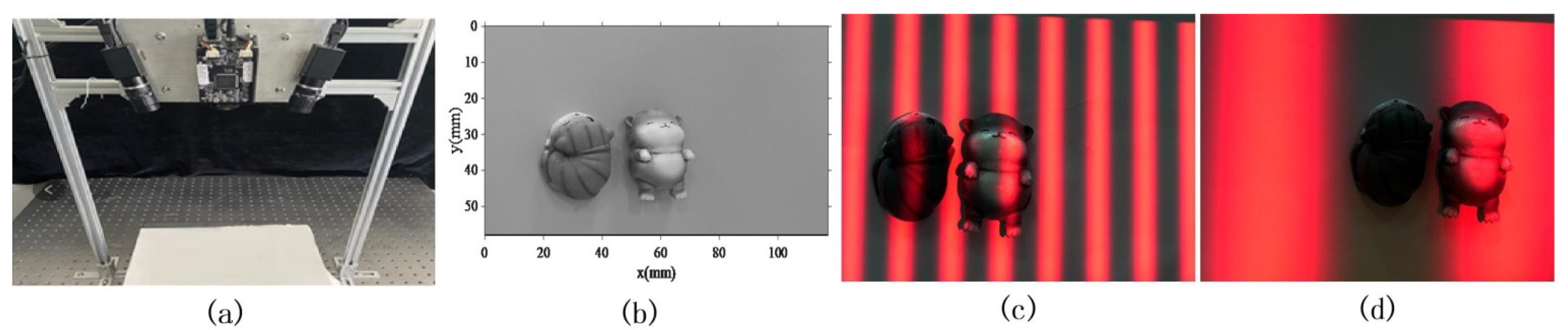
The experimental setup is shown in Figure 1a. It includes two color cameras (Manta 504C with 2452 × 2056 resolution, Allied Vision Technologies Inc., Freistaat Thuringen State, Germany) and a projector (Wintech DLP PRO 4500 with 912 × 1140 resolution, Wintech Digital System Technology Corp., Beijing, China). Please note, only one camera is used in the proposed method. The isolated models shown in Figure 1b are reconstructed by the proposed method based on three-step PSP. As the isolated objects are reconstructed, the dual-frequency phase unwrapping method is employed. Two-dimensional movement is applied on the object during the reconstruction. The same with the method in [16], a red fringe pattern is projected for convenient movement tracking. With the captured images, the red channel provides the sinusoidal fringe information, and the blue channel contains the pure object image without the fringe pattern. Then, the phase information and object movement information can be retrieved from the images in different channels. Three images are captured, respectively, during the projection of the high frequency (30 pixel/fringe) and low frequency (150 pixel/fringe), and Figure 1c,d show their first image.
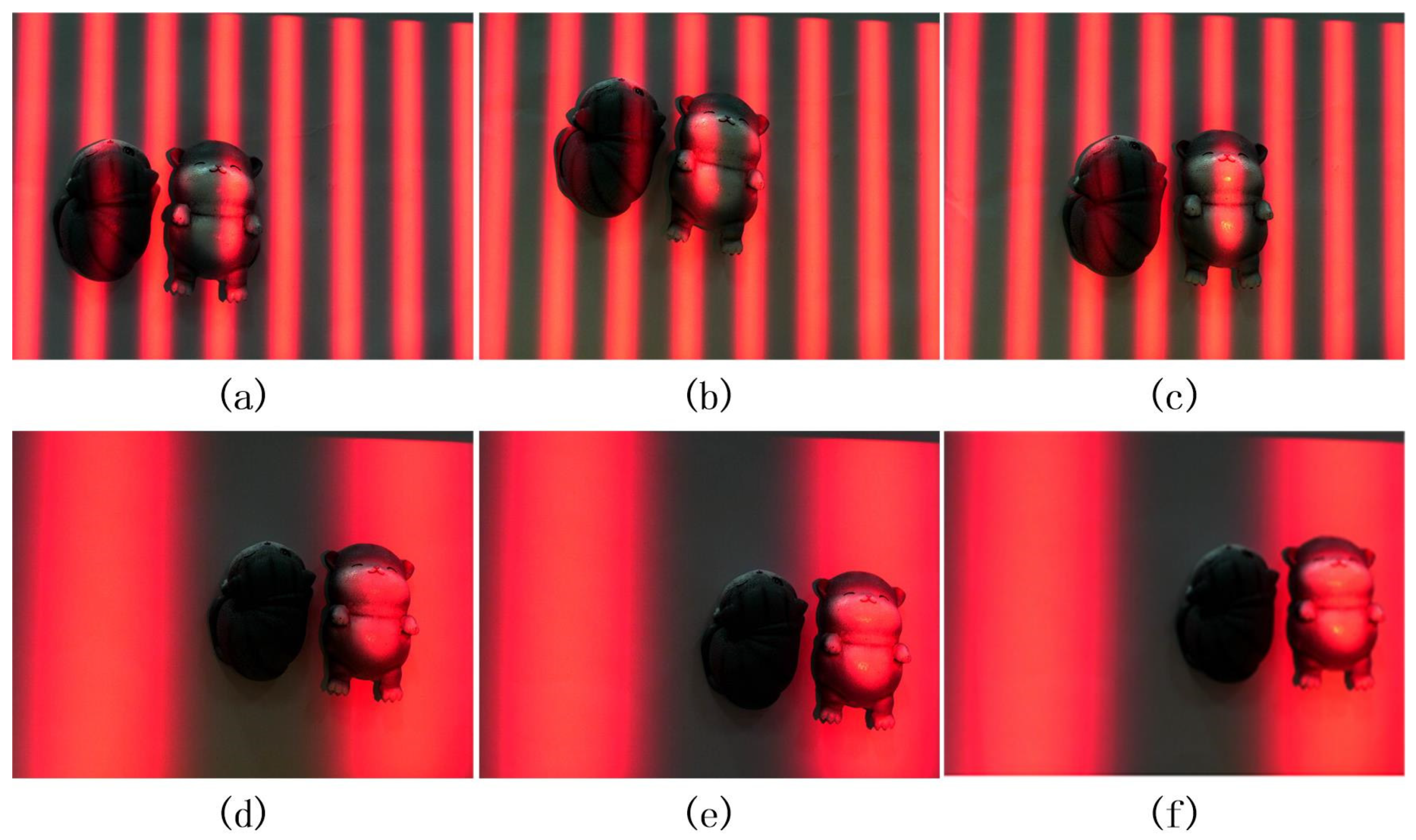
At the beginning, the high frequency fringe pattern is projected and three images with object motion are captured, as shown in Figure 2a–c. Then, the low frequency fringe pattern is projected and three images with motion are captured, as shown in Figure 2d–f.
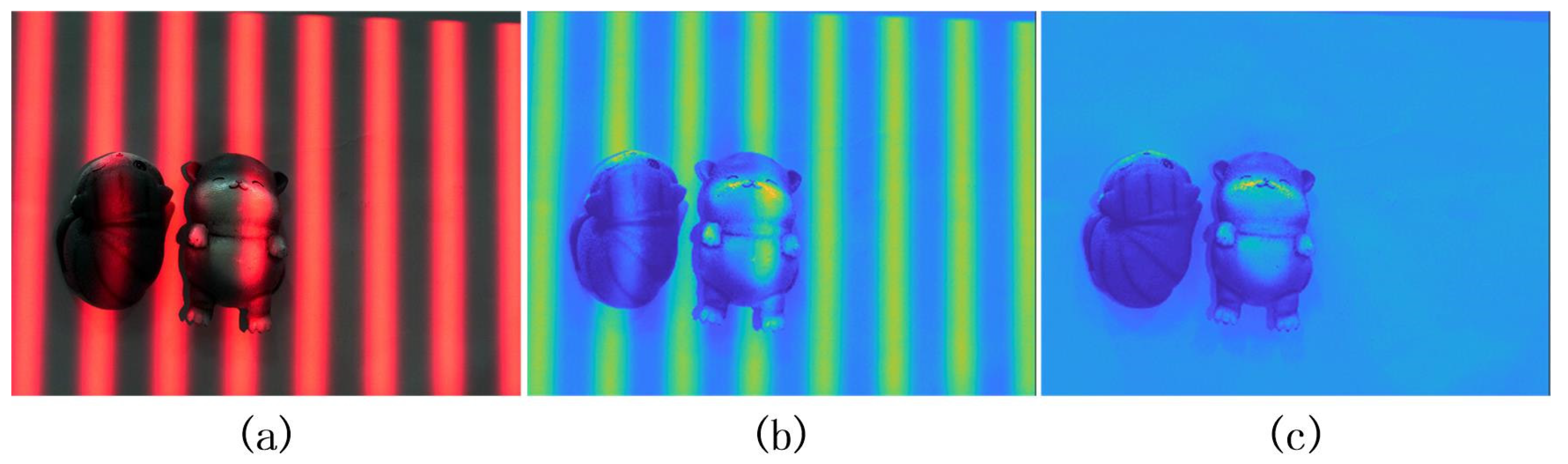
As the fringe pattern is projected in red color, therefore, in the object image shown in Figure 3a, the sinusoidal fringe pattern is contained in the red component (as shown in Figure 3b). In the blue component, the pure object image can be found as presented in Figure 3c.
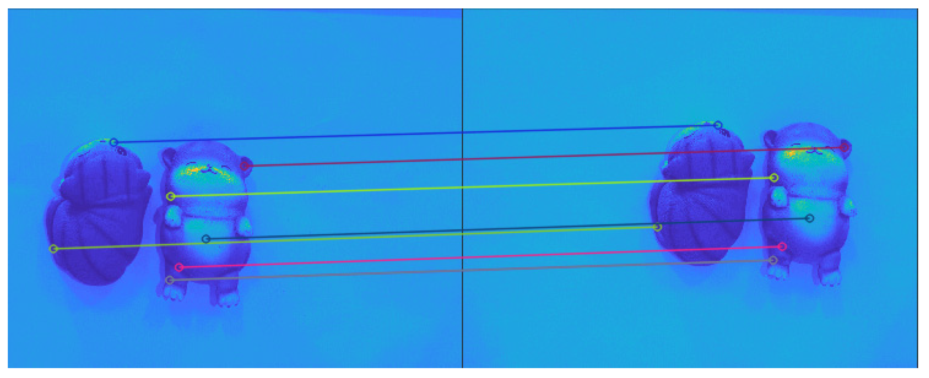
The SIFT (scale-invariant feature transform) [21] algorithm is implemented on the blue component images to track the object movement, as shown in Figure 4. Then, the rotation matrix and translation vector are calculated by the SVD (singular value decomposition) algorithm [18].
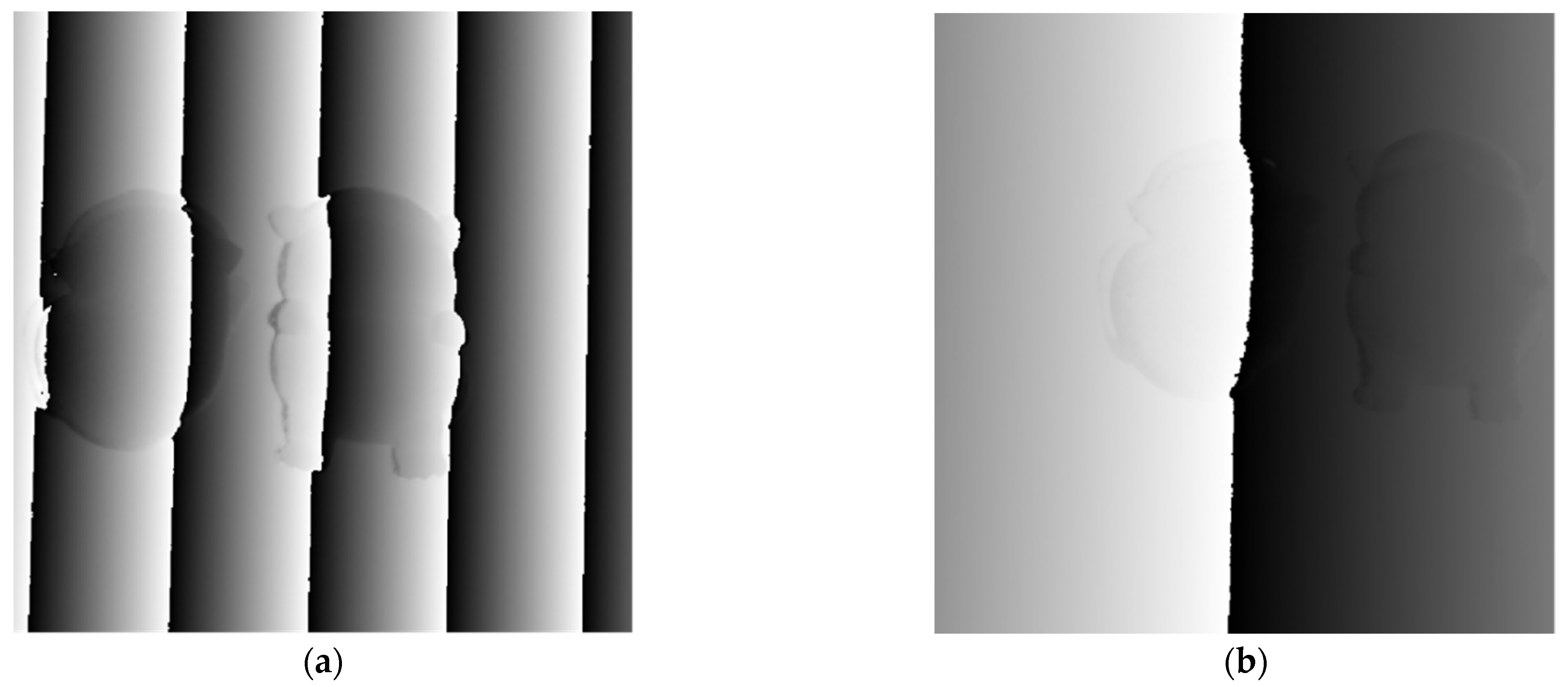
Based on the movement information, the wrapped phase maps for the two frequencies are obtained. The results are shown in Figure 5. A significant position mismatch is introduced by the object motion.
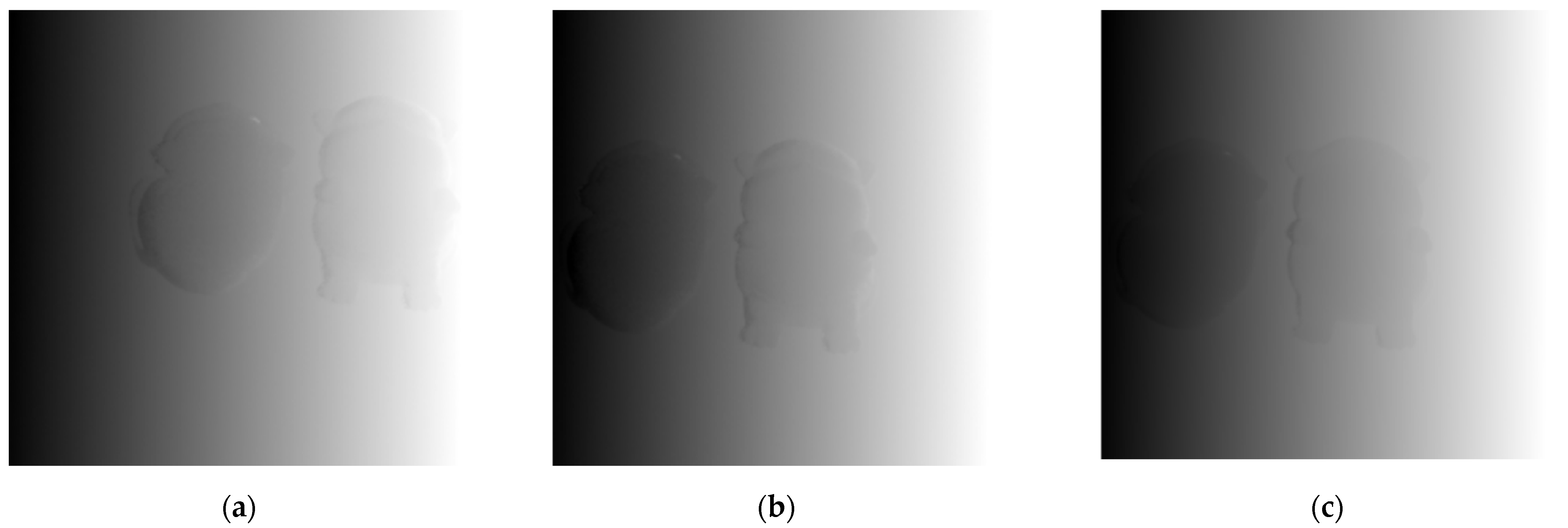
In order to unwrap the phase value of the high frequency, the phase value of the low frequency was unwrapped, as given in Figure 6a. The position mismatch between the wrapped phase maps of the two frequencies should be removed. The object position in the low frequency is moved to the object position in the high frequency. Then, the phase variation caused by the motion is compensated by Equation (18) (shown in Figure 6b). Then, the dual-frequency unwrapping method is applied, and the result is shown in Figure 6c.
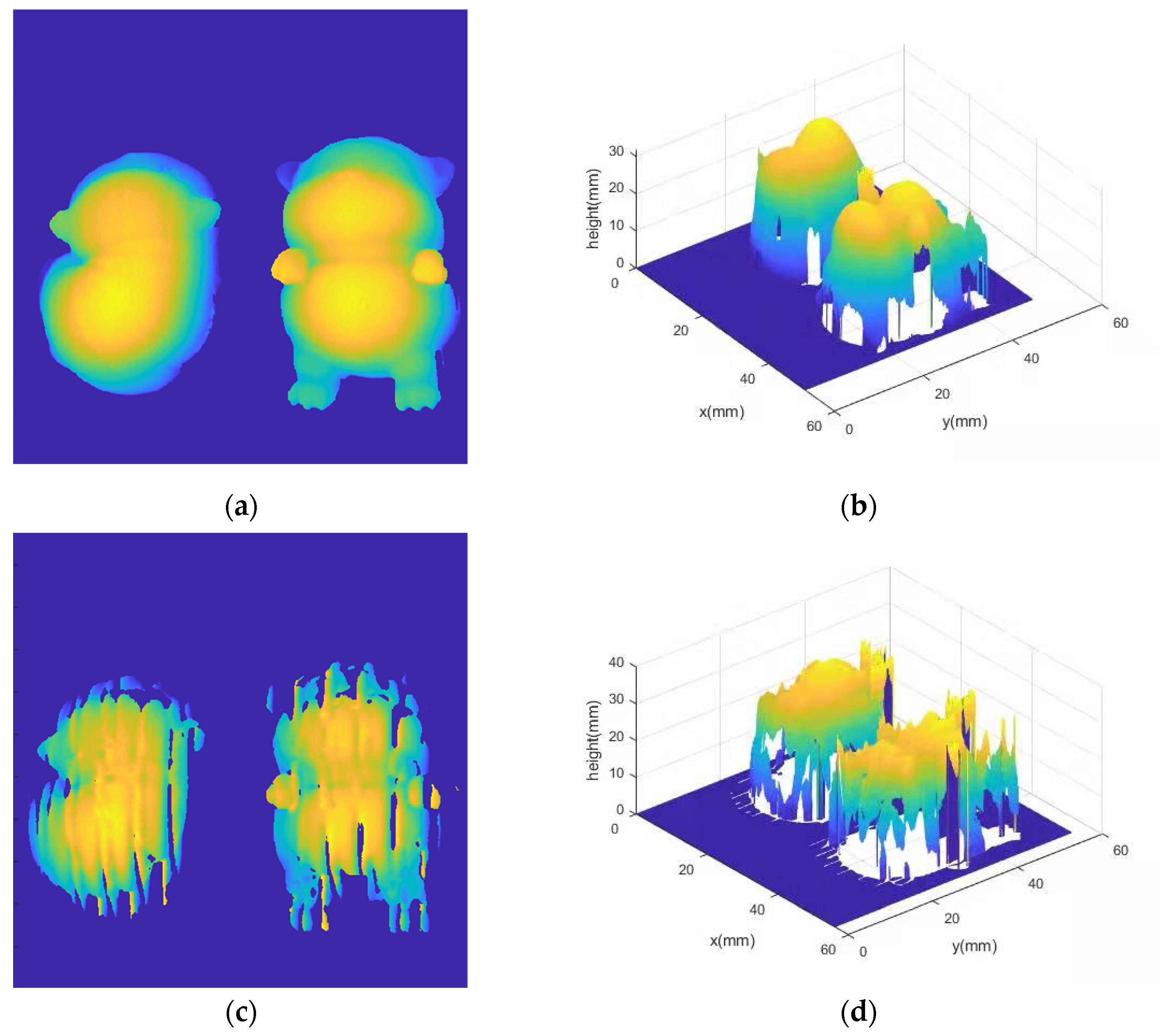
With the correct phase map, the object is reconstructed successfully, as presented in Figure 7a,b. It is apparent that the object is reconstructed well. The object is reconstructed by the traditional PSP for comparison (as given in Figure 7c,d). It can be seen that a high-accuracy result is achieved by the proposed method, and the motion-induced error is removed.
The RMS (root mean square) error is employed to evaluate the accuracy of the proposed method. The true value of the object is obtained by the eight-step traditional PSP algorithm with the static object. With the proposed method shown in Figure 7a,b, the RMS error is 0.073 mms and 6.775 mm for the traditional PSP in Figure 7c,d.
The error source of the proposed method may come from the following aspects. (1) Movement tracking: As the proposed method utilizes the movement information to compensate the motion-induced error, the accuracy of the movement tracking is important for the reconstruction accuracy. This paper employs the SIFT algorithm to track the movement. The SIFT algorithm can achieve a subpixel level tracking accuracy. Other movement tracking methods can be used to pursue higher reconstruction accuracy. (2) Movement mismatch: When the object movement is tracked, the corresponding points on the object before movement and after movement can be obtained. However, affected by the tracking accuracy and difference in the view of the camera, the movement mismatch will still exist. Improving the tracking accuracy and minimizing the difference of the view before movement and after movement will be helpful for reducing the movement mismatch.
Please note that, as the proposed method introduces the phase shift by motion, the object can have movement in any direction except parallel to the fringes. When the movement direction is parallel to the fringes, there is no phase shift generated. The details can be found in [17]. From the derivation of the proposed method, there is no limitation on the selection of the frequency. However, as two frequencies are employed to unwrap the phase value, the frequency of the fringe pattern should be designed according to the rules of the dual-frequency phase unwrapping method. The proposed method requires capturing the moving object without blur. Therefore, the camera capture speed should be increased when the object’s movement speed is fast. There are also no specific limitations on the object size. However, the object is required to stay within the scene of the camera, which is also a requirement of traditional PSP.

5. Conclusions

The isolated objects are reconstructed by projecting only two fringe patterns with different frequencies. The phase shift required in traditional PSP is introduced by object motion. The phase information of the object in the two frequencies is retrieved first. Then, the position mismatches and phase variation between the wrapped phase maps at different frequencies are compensated. The isolated objects are reconstructed successfully.

Author Contributions

Conceptualization, L.L. and K.W.; methodology, L.L. and M.L.; software, M.L.; validation, M.L.; formal analysis, L.L.; investigation, L.L.; resources, K.W.; writing—original draft preparation, L.L. and M.L.; writing—review and editing, L.L., M.L. and J.X.; visualization, M.L.; supervision, L.L. and K.W.; project administration, K.W. All authors have read and agreed to the published version of the manuscript.

Funding

This research was funded by the Key R&D Program of the Hubei Province of China (2020BAB120), the Major Public Welfare Project of Henan Province (201300311200), the Central China Normal University of Research Projects (No. CCNUTEIII 2021-05) of National Teachers’ Development Cooperation Innovation Experimental Base Construction and the teaching Innovation Research project Generative strategy Teaching Design and Application in Immersive Virtual Environment (No.ZNXBJY202111) of the Faculty of Artificial Intelligence Education.

Institutional Review Board Statement

Not applicable.

Informed Consent Statement

Not applicable.

Data Availability Statement

All data are presented in this article in the form of figures.

Conflicts of Interest

The authors declare no conflict of interest.

References

  1. Zuo, C.; Feng, S.; Huang, L.; Tao, T.; Yin, W.; Chen, Q. Phase shifting algorithms for fringe projection profilometry: A review. Opt. Lasers Eng. 2018, 109, 23–59. [Google Scholar] [CrossRef]
  2. Zhang, S. High-speed 3D shape measurement with structured light methods: A review. Opt. Lasers Eng 2018, 106, 119–131. [Google Scholar] [CrossRef]
  3. Feng, S.; Zuo, C.; Zhang, L.; Tao, T.; Hu, Y.; Yin, W.; Chen, Q. Calibration of fringe projection profilometry: A comparative review. Opt. Lasers Eng. 2021, 143, 106622. [Google Scholar] [CrossRef]
  4. Flores, J.L.; Stronik, M.; Muoz, A.; Garcia-Torales, G.; Cruz, A. Dynamic 3D shape measurement by iterative phase shifting algorithms and colored fringe patterns. Opt. Express 2018, 26, 12403–12414. [Google Scholar] [CrossRef] [PubMed]
  5. Gorthi, S.S.; Rastogi, P. Fringe projection techniques: Whither we are? Opt. Lasers Eng. 2010, 48, 133–140. [Google Scholar] [CrossRef] [Green Version]
  6. Lu, L.; Jia, Z.; Luan, Y.; Xi, J. Reconstruction of isolated moving objects with high 3D frame rate based on phase shifting profilometry. Opt. Commun. 2019, 438, 61–66. [Google Scholar] [CrossRef]
  7. Lu, L.; Suresh, V.; Zheng, Y.; Wang, Y.; Xi, J.; Li, B. Motion induced error reduction methods for phase shifting profilometry: A review. Opt. Lasers Eng. 2021, 141, 106573. [Google Scholar] [CrossRef]
  8. Gao, J.; Cao, Y.; Chen, J.; Huang, X. Online Phase Measurement Profilometry for a Fast-Moving Object. Appl. Sci. 2021, 11, 2805. [Google Scholar] [CrossRef]
  9. Li, B.; Liu, Z.; Zhang, S. Motion-induced error reduction by combining Fourier transform profilometry with phase-shifting profilometry. Opt. Express 2016, 24, 23289–23303. [Google Scholar] [CrossRef]
  10. Feng, S.; Zuo, C.; Tao, T.; Hu, Y.; Zhang, M.; Chen, Q.; Gu, G. Robust dynamic 3-d measurements with motion-compensated phase-shifting profilometry. Opt. Lasers Eng. 2018, 103, 127–138. [Google Scholar] [CrossRef]
  11. Li, L.; Zheng, Y.; Yang, K.; Su, X.; Wang, Y.; Chen, X.; Li, B. Modified three-wavelength phase unwrapping algorithm for dynamic three-dimensional shape measurement. Opt. Commun. 2021, 480, 126409. [Google Scholar] [CrossRef]
  12. Wu, H.; Cao, Y.; An, H.; Li, Y.; Li, H.; Xu, C. Fast and robust online three-dimensional measurement based on feature correspondence. Opt. Eng. 2021, 60, 074101. [Google Scholar] [CrossRef]
  13. Guo, W.; Wu, Z.; Zhang, Q.; Wang, Y. Real-time motion-induced error compensation for 4-step phase-shifting profilometry. Opt. Express 2021, 29, 23822–23834. [Google Scholar] [CrossRef] [PubMed]
  14. Guo, Y.; Da, F.; Yu, Y. High-quality defocusing phase-shifting profilometry on dynamic objects. Opt. Eng. 2018, 57, 105105. [Google Scholar] [CrossRef]
  15. Duan, M.; Jin, Y.; Xu, C.; Xu, X.; Zhu, C.; Chen, E. Phase-shifting profilometry for the robust 3-D shape measurement of moving objects. Opt. Express 2019, 27, 22100–22115. [Google Scholar] [CrossRef]
  16. Lu, L.; Jia, Z.; Pan, W.; Zhang, Q.; Zhang, M.; Xi, J. Automated reconstruction of multiple objects with individual movement based on PSP. Opt. Express 2020, 28, 28600–28611. [Google Scholar] [CrossRef] [PubMed]
  17. Wei, Y.; Lu, L.; Xi, J. Reconstruction of moving object with single fringe pattern based on phase shifting profilometry. Opt. Eng. 2021, 60, 084106. [Google Scholar] [CrossRef]
  18. Lu, L.; Ding, Y.; Luan, Y.; Yin, Y.; Liu, Q.; Xi, J. Automated approach for the surface profile measurement of moving objects based on PSP. Opt. Express 2017, 25, 32120–32131. [Google Scholar] [CrossRef] [PubMed] [Green Version]
  19. Zuo, C.; Huang, L.; Zhang, M.; Chen, Q.; Asundi, A. Temporal phase unwrapping algorithms for fringe projection profilometry: A comparative review. Opt. Lasers Eng. 2016, 85, 84–103. [Google Scholar] [CrossRef]
  20. Duan, M.; Jin, Y.; Chen, H.A.; Yan, K.; Chen, E. Dynamic 3-D shape measurement in an unlimited depth range based on adaptive pixel-by-pixel phase unwrapping. Opt. Express 2020, 28, 14319–14332. [Google Scholar] [CrossRef] [PubMed]
  21. Lowe, D. Distinctive image features from scale-invariant keypoints. Int. J. Comput. 2004, 60, 91–110. [Google Scholar] [CrossRef]
Figure 1. The isolated objects and fringe pattern. (a) The structure of the reconstruction system; (b) the image of the isolated objects; (c) the fringe pattern of high frequency; (d) the fringe pattern of low frequency.
Applsci 12 00252 g001
Figure 2. The captured object images of different frequencies. (ac) The object image of high frequency; (df) the object image of low frequency.
Applsci 12 00252 g002
Figure 3. The red component and blue component of the captured image. (a) The fringe pattern of the object; (b) the red component image of (a); (c) the blue component image of (a).
Applsci 12 00252 g003
Figure 4. The result of the SIFT algorithm.
Applsci 12 00252 g004
Figure 5. The wrapped phase maps of the two frequencies. (a) The high frequency wrapped phase map; (b) the low frequency wrapped phase map.
Applsci 12 00252 g005
Figure 6. The unwrapped phase maps. (a) The original unwrapped phase distribution of low frequency; (b) the phase map of (a) after position and phase variation compensation; (c) the obtained correct unwrapped phase map of high frequency.
Applsci 12 00252 g006
Figure 7. The reconstructed results. (a,b) The result obtained by the proposed method; (c,d) the reconstructed result with the traditional PSP.
Applsci 12 00252 g007
Publisher’s Note: MDPI stays neutral with regard to jurisdictional claims in published maps and institutional affiliations.

