1. Introduction
Currently, there still remains a high risk of emergency situations in the Russian Federation caused by household gas explosions. According to the official statistical data by the Russian Emercom, more than 1000 accidents caused by household gas explosions were registered from 2016 through 2020. Such events are widespread and are triggered by a variety of causes. The causes of cooking-gas explosions in residential neighborhoods are stipulated by a range of interconnected factors (circumstances) of a technical or regulatory nature or involve human factors [
1,
2,
3,
4,
5,
6,
7,
8].
Three consequently emerging events appear to constitute the required conditions for an indoor gas explosion: a gas leak from the gas supply system, a gas accumulation up to an explosive concentration, or introduction of an ignition source in a gassy room [
9,
10,
11,
12,
13,
14,
15,
16,
17]. A gas leak may generally occur within two scenarios: (a) an emission of a significant amount of gas within a short period of time as a result, for instance, of an emergency depressurization of the supply gas pipe; (b) a slow (with low gas flow) accumulation of gas inside a room from, for example, an unlit or flamed-out burner of a gas cooker [
18,
19,
20,
21,
22,
23].
When inflammable substances escape from gas cookers in households or professional equipment at industrial sites, there an explosive and flammable mixture appears [
24,
25,
26,
27].
Explosive accidents most frequently take place inside buildings. They entail not a detonation but rather of a deflagration kind of explosion transformation, which defines the specifics of explosion-load prediction methods, as well as consequential mitigation approaches [
28,
29,
30,
31].
Excessive pressure in an internal deflagration explosion in an enclosure might be as high as 700...900 kPa, which would result in the destruction of any construction site. However, as demonstrated by publications in the area of blast resistance and explosion safety of buildings under construction, such as those published by Moscow State University of Civil Engineering (MGSU) and National Research University, protective structures (PS), such as paned-window openings and explosion-venting structures (EVS), may significantly reduce explosive pressure to a safe level, in the range of 2–4 kPa [
32,
33]. The maximum pressure for premises with glass-paned blast-relief openings (windows) mainly depends on the fracture-initiation pressure. For EVS-equipped premises, the maximum value of explosive pressure depends on the EVS start-to-open pressure, the response time of the structure, and characteristic dimensions of the premises.
When flame approaches a blast-relief opening, the density of the outgoing gasses changes abruptly. This generates the first maximum in the pressure-versus-time characteristic. The second pressure surge corresponds to the maximum flame-front area in a steady flow of combustion products through the relief openings.
In the presence of explosion-venting structures, there is an additional pressure spike (maximum) in the explosive-pressure time law located before the first pressure surge. Its value depends on the characteristic dimensions of the room, the EVS response rate (lag), and the size of the opening. In some cases, for example, for small volumes, the EVS-triggered maximum pressure and the first pressure surge may merge, which makes analysis of experimental data more difficult.
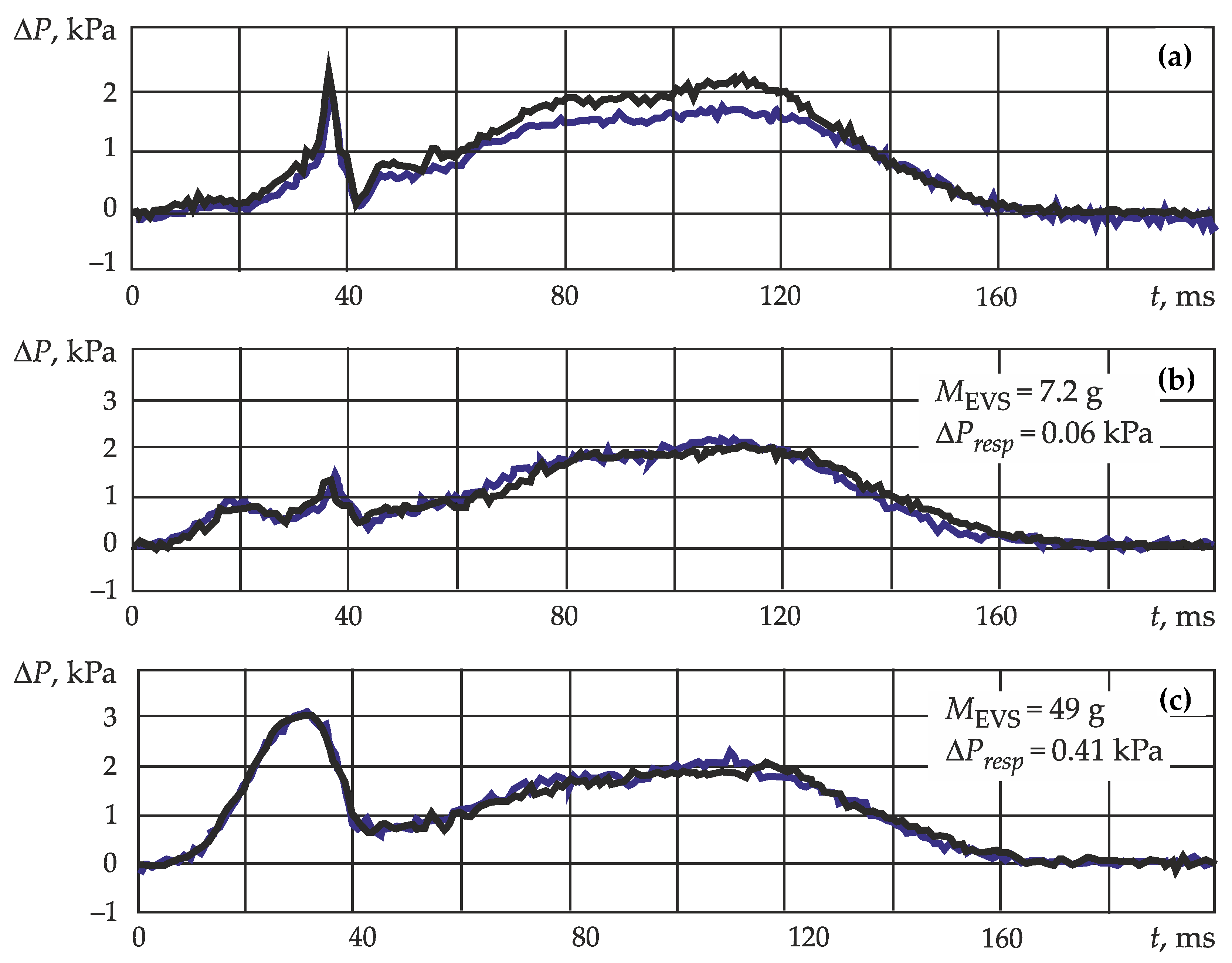
Figure 1 illustrates how the first pressure surge gets absorbed by the EVS-triggered maximum pressure, showing experimental waveforms (oscilloscope pressure patterns) of explosive pressure in a room with an uncovered opening and an EVS-equipped opening.
The explosive-pressure-dynamic parameter-calculation program that we developed accurately describes the explosive-load generation process in premises with no protective structures (PS), as well as in EVS-equipped premises. The data in
Figure 2 illustrate this.
Mathematical description of the explosive-load dynamics registered in a room with an EVS-equipped opening is based on the solution of simultaneous differential equations, which link together explosive pressure and EVS kinematics. A general overview of the simultaneous equations will be provided below. For now, let us focus on the influence of premises dimensions and the mixture type on explosive-load levels.
Analysis of the simultaneous equations (see Equations (3) and (5) below), presented in a non-dimensional form (Formulas (1) and (2)):
where
B is the key parameter defining the pressure surge caused by an EVS. It represents a non-dimensional acceleration of the EVS movement under the pressure forces emerging from an explosion of a certain mixture type, non-dimensional parameter
B being its characteristic.
The physical significance of parameter
G is as follows: the greater the linear dimensions of the building, the lower rate of increase explosive pressure as the overall duration of the explosion extends [
34,
35,
36,
37,
38]. Therefore, the impulse of the pressure force grows in direct proportion with building dimensions. This, in turn, leads to a larger impulse transferred by the pressure forces to the EVS. On the other hand, the longer the delay of the EVS, the lower the speed at which the EVS moves (for a given impulse). Thereforem, as the dimensions of the building (premises) grow, non-dimensional acceleration increases, and vice-versa.
Dimensionless parameter B is characteristic of the type and the quality of the burning mixture. The physical significance of parameter B lies in the fact that with a growing flame-propagation rate, the emission rate of combustion products increases. In dimensionless terminology, it affects how efficiently the mixture is discharged to the atmosphere through relief openings. The capacity of combustion products drops as long as parameter B decreases or the visible flame-propagation rate increases.
While pressure surges (in a situation with an EVS-equipped opening), the flame front represents a sphere that significantly simplifies the calculation task. Acceleration of explosive combustion at this point can be provided only by initial turbulization of the mixture, which would depend on the actual accident scenario. Combustion-process intensification related to the presence of various obstacles along the flame path plays a subordinate role at the initial stage of the explosion because the visible flame-propagation rate is minimal.
Figure 3, which contains instant photos of a deflagration explosion inside a room with a hinged window, illustrates a statement about the spherical nature of the flame front at the moment of EVS opening.
Photos 1 and 2 of
Figure 3 show that the flame front has an almost spherical shape at the initial stage of the explosion and even at the moment when the EVS panel starts to open. It is only when the flame breaks out into the atmosphere, which corresponds to the first pressure surge (photo 3
Figure 3), when the flame front loses its spherical shape.
The influence of the EVS response rate on the explosive pressure is shown in
Figure 4, which shows explosive-pressure waveforms for an enclosure equipped with an EVS a with varying response rate.
When using EVSs in explosion-hazardous buildings and premises to provide resistance in the case of an emergency explosion, there arises a question about maximum explosive loads that will emerge at a particular EVS.
The goal of this research is to justify the possibility of an EVS design upgrade that would allow for a reduction in the explosive load (which is generated due to the presence of the EVS on the relief opening) to the level corresponding to the start-to-open pressure of the EVS. The proposed design upgrade is based on analysis of physical processes accompanying EVS opening during an accidental explosion.
2. Experimental Setup and Experimental Procedure
Research was conducted on a test rig used to simulate the influence of internal accidental explosions on explosion-venting systems (EVS) in accordance with the National Standard GOST R 56289-2014. The test rig includes: an explosion chamber; a flammable gas-supply and mixing system; a remote gas-ignition system; an excessive-pressure measuring, registering, and processing system; and a high-frame-rate video-recording system. The explosion test chamber is capable of withstanding an excessive explosion pressure of up to 100 kPa and has a relief valve that opens when excessive pressure reaches 20 kPa. The chamber’s volume is 8 m3 and is cubic in shape. The opening in the chamber where an EVS is installed is 1700 × 1500 mm. Inside the chamber, there is a flammable gas-supply system, a fan for gas-air mixture homogenization, an automatic ignition device, and a chamber-ventilation fan to extract the remaining combustion products when tests are completed.
The gas-supply system includes a gas cylinder, a gas meter with a tolerance of ± 3%, and a gas-mixing system that provides a stoichiometric mixture throughout the entire volume of the chamber. The mixing system includes a spark-resistant fan installed inside the explosion chamber with an airflow capacity of 3000 m3/hour minimum and a remote-control system.
The pressure-measuring and registering system includes: static excessive-pressure ports; a source of direct current for pressure sensors; an analog-digital converter; and a PC with relevant software capable of providing pressure time-law graphs and saving the obtained data for further processing.
The filming system contains a high-frame-rate camera with a frame rate of 1000 frames per second and a resolution of 1280 × 720 pixels, as well as software for frame-by-frame analysis.
The tests were conducted under an outside air temperature of +18 °C. The explosion chamber was supplied with an amount of flammable gas needed to create a stoichiometric mixture. Then, the mixing system inside the chamber was switched on. The mixing system was on for at least one minute in order to provide an even stoichiometric mixture throughout the entire volume of the chamber. The mixing system was then switched off, and the gas mixture was ignited.
During the test, the following parameters were registered: the change in excessive pressure in time inside the explosion chamber was recorded through excessive-pressure sensors; the process of EVS discharging from the blast-relief opening was recorded by registering the outside distance between the EVS and the blast-relief opening. The moment of EVS opening is the time from the mixture ignition until the instant when the distance between the EVS and the relief opening is at least 1 cm.
The test results were evaluated with regard to excessive EVS opening pressure (pressure values of similar experiments should not vary by more than 20%).
2.1. Numerical Experiment
In order to determine the dynamics of excessive pressure inside an EVS-equipped room, the following common differential equation should be solved [
34]:
where
P(
t) is the current pressure value; Δ
P is excessive pressure;
S(
t) is the current value of the flame-front surface area;
Sop is the overall area of relief openings;
ρj is the density of the cold mixture (
ρ1) or combustion products (
ρ2);
ε is the degree of mixture expansion;
γj is the specific heat ratio of the fresh mixture (
γ1) or combustion products (
γ2);
Un is the normal flame-propagation rate;
Vj is the current volume of fresh mixture (
V1) or combustion products (
V2);
α is the combustion-intensification coefficient;
μ is the flow-rate coefficient for the gases that escape through the relief opening;
is the functional relationship between the residual obstruction of the relief openings and the protective structures; and
is the current value of the relief-opening areas that are clear of protective structures.
For premises equipped with blowout EVS, the functional relationship between the residual obstruction of the relief opening and the EVS can be presented in the following form:
where
S1op is a single opening area,
NEVS is the single EVS perimeter,
x(
t) is the EVS shift, and Δ
Pop is the excessive pressure when opening of the venting panel occurs.
For turning structures, the functional relationship between the residual obstruction of the relief opening and the EVS will be somewhat different from that in (4).
It can be deduced form (4) that in order to determine
f(
t), we need to know the EVS shift-versus-time characteristic,
x(
t). For this to be determined, Equation (3) should be supplemented with two common simultaneous differential equations:
where
V(
t) is the EVS shift velocity;
is the structure-responsiveness parameter;
K is the EVS location parameter (
K = 1 when EVS is located on the roof of the building,
K = 0 when EVS is located on the walls of the building);
g is the acceleration of gravity; and
m is the mass of a single venting structure.
The simultaneous Equations (3) and (5) need to be solved with regard to the following initial conditions:
where Δ
Pop is the EVS panel start-to-open pressure.
When solved, the simultaneous equations provide the required excessive pressure inside the EVS-equipped premises.
The calculation results conducted according to the above-mentioned method and the followup discussion will be presented following analysis of experimental data obtained at the full-scale test site.
2.2. Full-Scale Experiment
Tests were conducted of window-case samples, which represent a shiftable, transparent explosion-venting structure made of 1550 × 1250 mm PVC profiles. The test sample consists of an inner and outer window case. The outer case was attached to the opening with 8 screws. The inner case was installed inside the outer case and was held in place with 8 brackets, which served as protective locking devices. The inner case is split in 2 parts by an impost and hinged doors, with one-chamber glass units installed inside half.
The EVS operating principle is based on the fact that the protective locking devices break when window is exposed to an excessive explosion pressure. The pressure force shifts the window outward, with no need for any other energy source.
When the sample was installed, the explosion chamber was supplied with an amount of flammable gas needed to create a stoichiometric mixture. A gas analyzer was used to control the concentration. Gas supply was stopped when a required concentration of the gas-air mixture inside the chamber was achieved.
The mixture was ignited 30 s or less after gas supply was cut off. The following parameters were registered for the experiment: change in excessive pressure in time, clearing of the chamber’s relief opening from the shifted EVS, and typical destruction of the sample.
The integral data obtained during EVS sample tests are given in
Table 1.
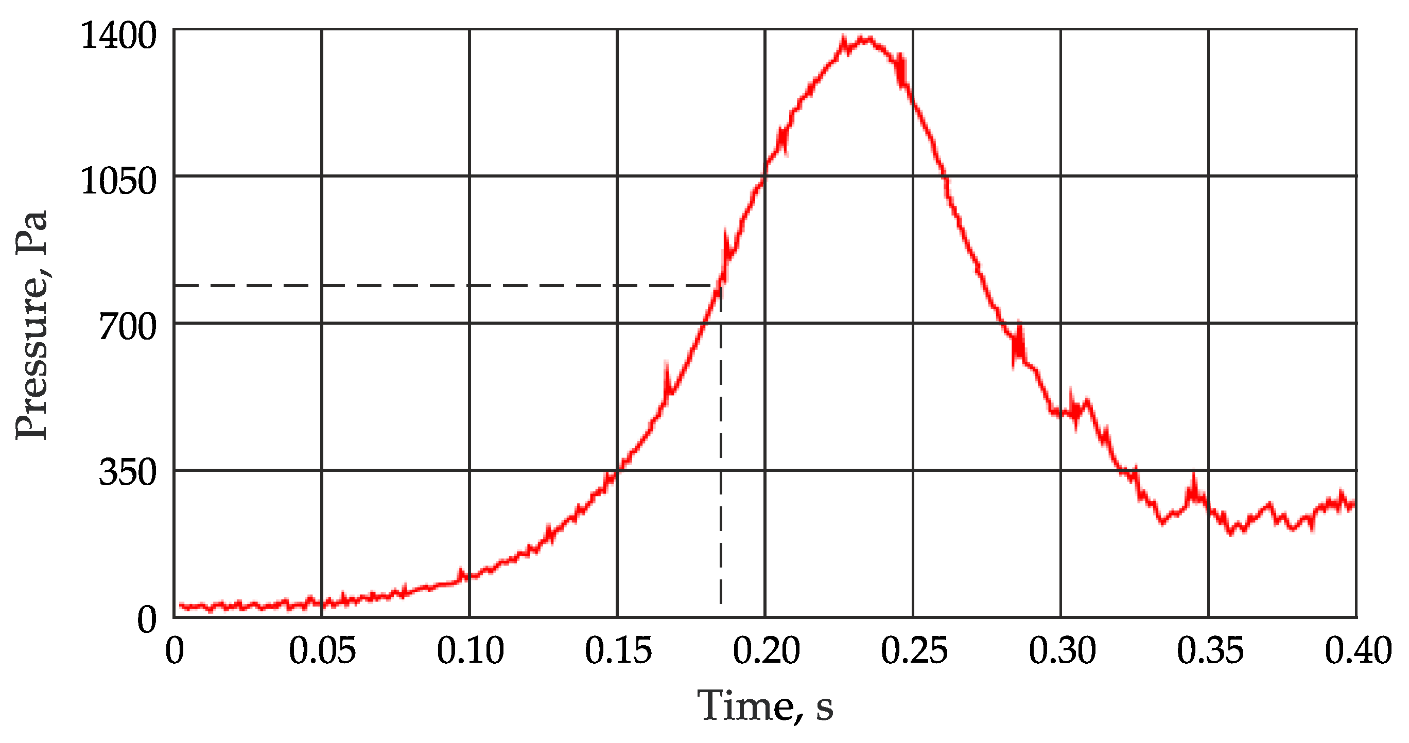
Experimental waveforms of excessive pressure obtained through full-scale research are shown in
Figure 5,
Figure 6 and
Figure 7.
Figure 8 provides instant photos of several moments of a deflagration explosion process inside the chamber involving shedding of an EVS installed in the relief opening.
Tests of the ‘shiftable, transparent explosion-venting PVC profile window’ samples demonstrated their operation capability, i.e., the ability to clear the relief opening of the building under excessive pressure generated by an internal deflagration explosion of a gas-air mixture. The actual value of excessive EVS panel-opening pressure comprised 0.808 kPa.
3. Results
The theoretical correlations provided earlier, in combination with the experiment results, demonstrate that the maximum explosion pressure in EVS-equipped premises depend on various parameters related to the venting structure (its dimensions and specific weight), as well as flammable-mixture properties and room dimensions.
Minor structural features of the EVS allow us to narrow the maximum explosive-pressure values to one EVS parameter—the initial panel-opening pressure, Pop. To achieve this, the EVS or enclosing structures of the premises should be designed to have relatively small openings covered with crushable membranes, for instance, common glass or small-sized blowout panels. The only requirement for those additional openings is that they should be shed (Pshed) at pressure values a little higher than the main EVS panel-opening pressure (Pshed > Pop), while the opening area should constitute 10% or more of the overall EVS area. This very upgrade of the EVS allows for the provision of maximum explosive loads corresponding to the membrane-destruction pressure on additional relief openings or the shedding pressure (Pshed).
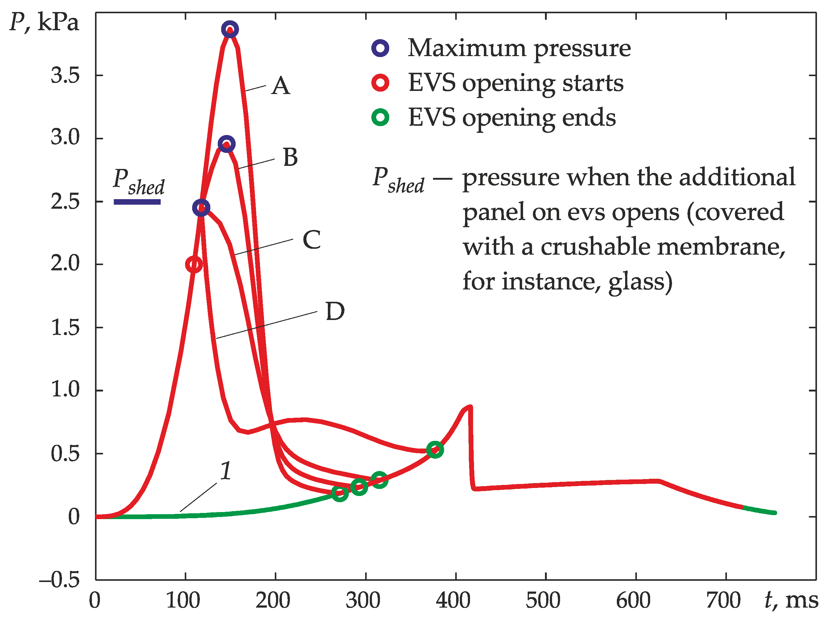
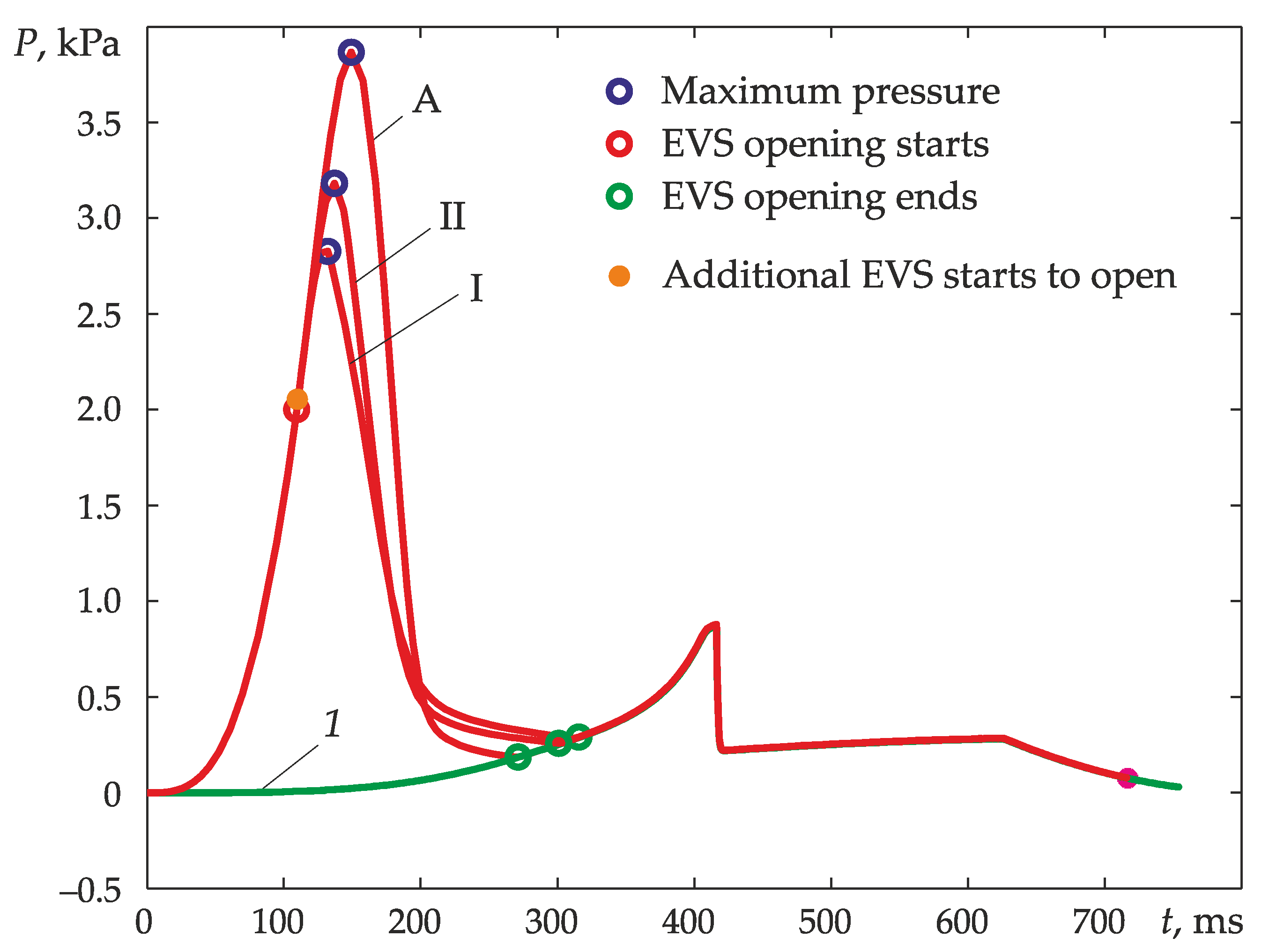
To illustrate the efficiency of an upgraded EVS,
Figure 9 provides the calculation results of explosive pressure inside a kitchen.
The premises under consideration had the following dimensions: 2.75 × 3.0 × 4.0 m, with a 1.5 × 2.0 m window opening, a hinged EVS with a response rate of 0.5 kPa (50 kG/m2) and an opening pressure of Pop = 2 kPa. The additional opening in the EVS opens when pressure reaches Pshed = 2.5 kPa. Calculations were conducted for a non-upgraded EVS and for EVSs with an additional 0.1 m2 (3.34% of the EVS surface area), 0.25 m2 (8.35% of the EVS surface area), and 0.5 m2 (16.7% of the EVS surface area) opening.
Figure 9 provides calculations of explosive pressure with a fully open window area (curve
1).
The operational principle of the suggested EVS upgrade is as follows. With no additional opening equipped with a crushable or sheddable membrane, pressure inside the room increases in the following way. First, explosion pressure increases in an enclosed space. When the pressure reaches the EVS opening value,
Pop, arresting devices break, and the EVS starts to shift. Explosion pressure increases further as flame-front area increases and, correspondingly, the inflow of combustion products increases. Their withdrawal at this stage is insignificant because the EVS shift is minimal, and the shed window is only a slightly open. As the EVS gets shifted further, the area of the opening increases, and at a certain point, the inflow of combustion products is fully compensated for by the discharge of gases through the opening window. That is the moment when the pressure caused by the presence of the EVS reaches its maximum. Further shifting of the structure increases the opening area and leads to a pressure decrease. When the opening is clear of the EVS, the explosive-pressure time law is identical to the pressure time law in a non-EVS-equipped room (see
Figure 9).
When an additional opening is used with a crushable or an easy-to-open element, which can be achieved by decreasing the dimensions of sheddable elements (increasing the division of EVS elements covering the additional opening), the pressure increase develops in the following way. Similarly to the previous case, first, explosion pressure increases in an enclosed space. Then, when the pressure reaches the EVS opening value,
Pop, the arresting devices break, and the EVS starts to shift. At this point (or a bit later), elements covering the additional opening are shed. This leads to a decrease in pressure, the rate of which is determined by the area of the additional opening. For instance, if the area of the additional opening is 3.34% of the overall EVS surface, or 0.1 m
2 (curve B,
Figure 9), the pressure does decrease, although insignificantly. If the area of the additional opening is increased to 0.25 m
2, which constitutes 8.35% of the total EVS surface area, a significant drop in pressure occurs, and the maximum explosion pressure does not exceed the protective-structure-collapse pressure at the additional opening,
Pshed (curve C,
Figure 9). A further increase in the area of the additional opening, up to 0.5 m
2, which is 16.7% of the total EVS surface area, leads to an abrupt decrease in explosion pressure at the moment of panel opening (curve D,
Figure 9). In terms of the blast resistance of the building, a further increase in the area is unreasonable.
Let us take a look at how the parameters of the devices covering the additional opening affect the level of explosion loads.
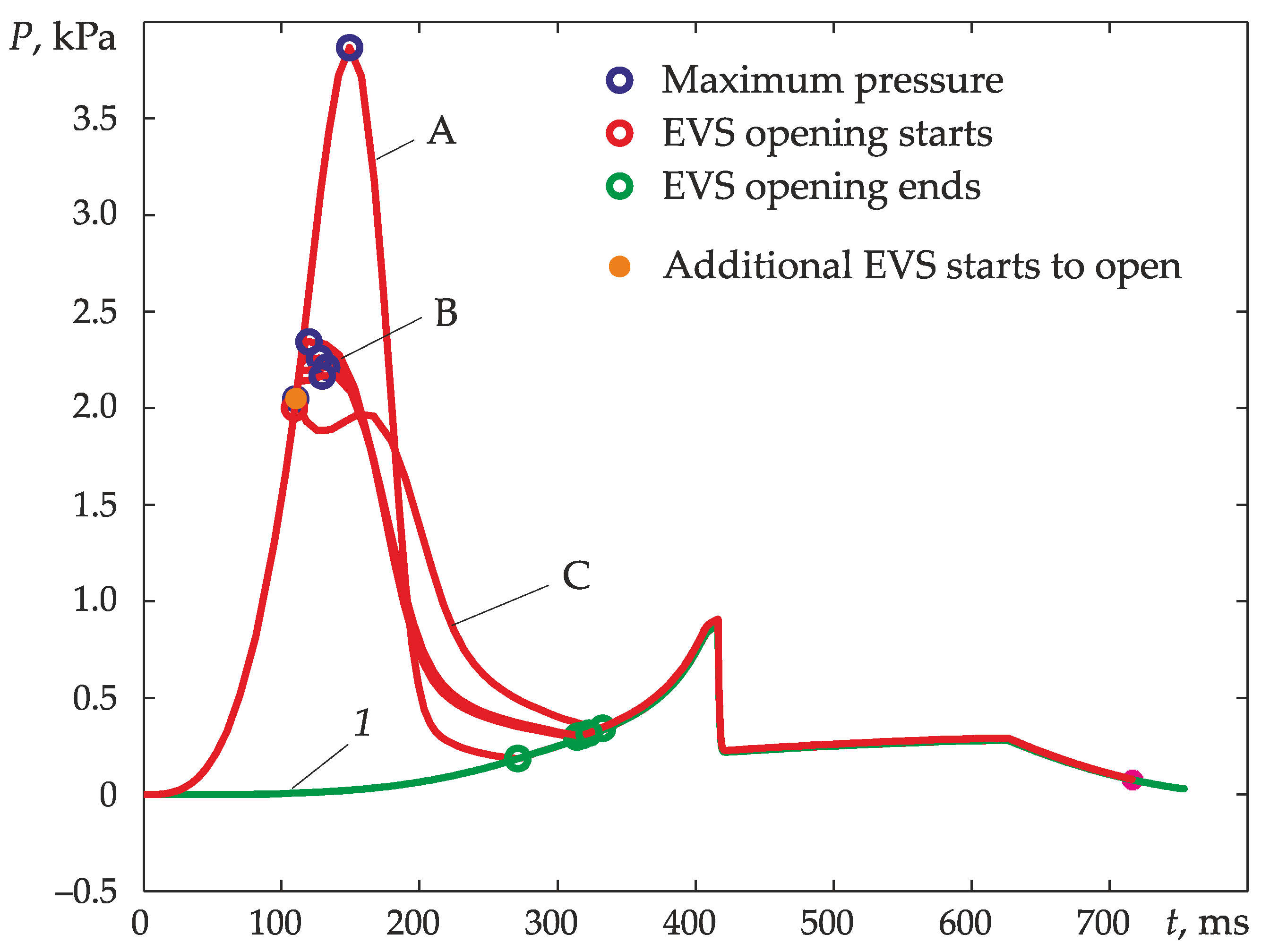
Figure 10 provides explosion-pressure relationships in a kitchen with various dimensions assumed at the first portion of calculations (
Figure 9). The total area of the opening is 3 m
2. The response rate of the EVS covering the opening is 0.5 kPa (about 50 kT/m
2).
Figure 10 (relationship A) demonstrates explosion-pressure dynamics inside a room with an EVS-equipped opening (dimensions indicated). Curve B (
Figure 10) depicts explosion pressure if an EVS with an additional opening is used. The area of the additional opening is 0.25 m
2, which is 8.33% of the total opening area. The additional opening is equipped with EVSs with a response rate of 0.5, 0.25, 0.125, and 0.05 kPa, which open up when the pressure reaches 2.05 kPa, and the EVSs have divisions (100 elements each). The explosion-pressure values, which will be registered in the kitchen when the indicated protection structures are used, are shown in
Figure 10 (curve B). The explosion pressure observed when the additional opening is covered with a crushable membrane (crushes when pressure equals 2.05 kPa) is given in
Figure 10 (curve C). Apart from that,
Figure 10 shows the relationship between the explosive pressure inside the premises and previously and fully open discharge windows (curve 1,
Figure 10).
When using EVSs with fewer division applied to the additional opening, the pressure-dropdown effect is less significant. This is illustrated by the calculations shown in
Figure 11, which provides explosive-pressure values when an EVS with no divisions is used in the additional opening. The EVS opening pressure is 2.05 kPa, and the response rates of the structure are 0.05 and 0.125 kPa.
It can be deduced from
Figure 11 that the best effect is achieved when the additional opening (quite small vent window) in the overall structure of the main sheddable window is cleared almost instantly. This can be achieved tby multiple divisions of the covering material used on the additional opening of the EVS or by using a crushable membrane, like glass, for instance, which breaks down into multiple fragments. From the physical perspective, an EVS with multiple divisions has a high response rate (curve C,
Figure 10).
