Article

Magnetically Deployable Robots Using Layered Lamina Emergent Mechanism

by
Tran Nguyen Lam Giang
1,
Catherine Jiayi Cai
1,2,
Godwin Ponraj
1 and
Hongliang Ren
1,3,*
1
Department of Biomedical Engineering, National University of Singapore, Singapore 117583, Singapore
2
Singapore Institute of Manufacturing Technology, Singapore 138634, Singapore
3
Department of Electronic Engineering, Chinese University of Hong Kong, Hong Kong 999077, China
*
Author to whom correspondence should be addressed.
Appl. Sci. 2022, 12(1), 14; https://doi.org/10.3390/app12010014
Submission received: 7 November 2021 / Revised: 9 December 2021 / Accepted: 14 December 2021 / Published: 21 December 2021
(This article belongs to the Special Issue New Trends in Robotics, Automation and Mechatronics (RAM))

Abstract

:
The steady rise of deployable structures and mechanisms based on kirigami and origami principles has brought about design innovations that yield flexible and lightweight robots. These robots are designed based on desirable locomotion mechanisms and often incorporate additional materials to support their flexible structure to enable load-bearing applications and considerable efficient movement. One tetherless way to actuate these robots is via the use of magnets. This paper incorporates magnetic actuation and kirigami structures based on the lamina emergent mechanism (LEM). Three designs of magnetic-actuated LEMs (triangular prism, single LEM (SLEM), alternating mirror dual LEM (AMDLEM)) are proposed, and small permanent magnets are attached to the structures’ flaps or legs that rotate in response to an Actuating Permanent Magnet (APM) to yield stick-slip locomotion, enabling the robots to waddle and crawl on a frictional surface. For preliminary characterization, we actuate the three designs at a frequency of 0.6 Hz. We observed the triangular prism, SLEM, and AMDLEM prototypes to achieve horizontal speeds of 4.3 mm/s, 10.7 mm/s, and 12.5 mm/s on flat surfaces, respectively. We further explore how changing different parameters (actuation frequency, friction, leg length, stiffness, compressibility) affects the locomotion of the different mechanisms.

1. Introduction

Mechanisms that mimic the natural locomotion patterns of animals have attracted much attention over the recent years. Various mechanisms reported in the literature incorporate compliant materials or structures due to their potential for adaptive interactions with unpredictable and complex environments [1,2]. In addition, the use of compliant structures reduces the need for bulky and rigid electrical components that are commonly used in traditional hard robots, reducing potential risks of accidents or injuries inflicted during interaction with the human body and enabling safer human–machine interaction [3]. Several types of animal-inspired locomotion mechanisms and their corresponding enabling fabrication approaches and actuation methods are also studied. In particular, annelids (such as earthworms and caterpillars) and snakes that rely on friction-enabled locomotion mechanisms such as peristalsis, inchworm, and undulation are popular inspirations for robots in applications that require them to access tight and narrow spaces while avoiding obstacles. In the following sub-sections, we review the different actuation mechanisms and bio-mimetic locomotion patterns reported in the literature.

1.1. Actuation Mechanisms

Actuation mechanisms for compliant mechanisms found in the literature include shape-memory alloys (SMA), dielectric elastomers (DEA), electric motors, and magnetic actuation. Among these actuation methods, magnetic actuation offers an advantage in minimally invasive biomedical applications as they are tetherless and add little mass to the overall mechanism architecture. In contrast, other actuation mechanisms often rely on external electrical stimulus (electrical motors) or heat (shape-memory alloys [4] and dielectric elastomer [5]), both of which require connecting wires to supply power. While electric motors are popularly used in traditional robots due to their simple and direct control, they often have rigid and bulkier components than other actuators. Table 1 summarizes the characteristics of different types of actuators and their associated advantages and limitations. Given the advantages associated with magnetic actuation, we chose to use it to control and actuate our robots in this paper.
Table 1. Summary of actuators used in literature for compliant mechanisms.
ActuationCharacteristicsAdvantagesDisadvantages
Smart memory alloys (SMA)
  • Activated by heating (e.g., electric current)
  • Operation range: 5–8% maximum strain/stroke
  • Light [6], flexible [7], simple control [8], large energy density per cycle, and high mass-specific force [1]
  • Slow cycle frequency due to cooling [9], small force/stroke generated per coil [10], low controllability [11]
Dielectric elastomer (DEA)
  • Activated by electric current.
  • Operation range: 40% strain/stroke
  • Large strain capability with high energy density, simple control [5], good stiffening capability and scalability [12]
  • Lower output force, high driving voltage, reliant on compliant electrodes [13], short lifetime
Pneumatic
  • Actuated by pressured air
  • Operation range: up to 28% strain/stroke
  • Great speed and power density, resilient to adverse external conditions with silicone body, scalable, less complex to produce
  • Challenge in containing high actuating pressure, short lifespan [14], hard to control due to non-linear system dynamic [15], complex supply system
Motors
  • Traditional motor designs use stiff joints and components
  • Operation range: depends on the type of motor used
  • High actuation speed [9], efficient, easy to control
  • Bulky and complicated mechanism, difficult for miniaturization, structural stiffness
Magnetic
  • Operation range: 15–25% strain/stroke [16]
  • Can achieve high power density when printed on soft materials. Untethered, EM actuators have high response speed and simple control [17]
  • Low-energy conversion [14], magnetic interference, magnetic actuators with permanent magnets have low controllability [18]

1.2. Biomimetic Locomotion

Biomimetic locomotion patterns are often inspired by worms and annelids, which rely on friction to generate directed motion. These biomimetic locomotion patterns include peristaltic, inchworm and stick-slip.
Peristaltic motions are the more commonly incorporated worm-like locomotion patterns. By incorporating various actuation methods and designs, research teams have mimicked and adapted certain movement features by studying earthworms. For example, Seok [7], Menciassi [11], and Onal [19] have attempted to create radial contraction and expansion mechanisms that underlie peristaltic motions by using shape memory alloys (SMA) or dielectric elastomers, which can be designed to respond in a specific manner in terms of shape or length upon applying voltage. The biomimetic crawler created by Menciassi [11] achieved peristaltic motion using an SMA spring that contracts under heat. The mechanism has a silicone shell with microhooks embedded in the shell to mimic setae by providing anchor points. Seok [7] reports a meshworm that incorporates a braided mesh-tube structure, wrapped around by nickel–titanium (NiTi) coil SMA actuators, which act as contracting muscles. The use of SMA coils as contracting muscles is also found in the designs of other soft mechanisms reported in [10,19,20]. Liu [21], Ge [22], and Jung [23] relied primarily on the axial expansion of the designed structures, with additional frictional features to achieve peristaltic-inspired forward movement. Liu [21], in particular, designed a pneumatically actuated earthworm-inspired mechanism with a kirigami skin to provide traction that anchors the mechanism’s head and tail during movement. The pneumatically actuated earthworm-inspired mechanism by Ge [22] is modeled as a double-mass-spring damper that can vary frictional forcers at its extreme ends. Wang [24] and Zuo [25] also employ designs and mechanisms inspired by earthworms using motors and motion transferring mechanisms to recreate the peristalsis motion for colonoscopy applications.
The inchworm motion relies on the linear contraction of longitudinal muscles while using friction at the head and the tail of the inchworm for directional motion. Studies made use of SMA actuators [6], double balloons [26], magnetic attraction [27], and electromagnetic oscillatory actuators [28] to contract the body of worm-inspired robots. Despite the differences in actuation methods, they primarily aim to mimic the bending of the mechanism body. These mechanisms also implement different ways to anchor either the structure’s head or tail to allow the other to slide. For example, Kim [27] relies on using materials that possess a higher friction coefficient in the rear “foot” of the magnetic-actuated structure to induce forward motion. Lee [28] designed claws that reduce the coefficient of friction in the forward direction relative to the backward direction.
Mechanisms that implement electromagnetic actuators rely on crawling locomotion created by impact-driven force or stick-slip mechanism. Ito et al. [29] generate a magnetic field using a coil surrounding a permanent magnet to achieve impulse-driven motion. Min et al. [30] achieved similar locomotion by moving a permanent magnet between two solenoids. Song et al. [17] used a series of solenoids and a combination of attraction and repulsion from magnet plungers to achieve bending. Other electromagnetic control systems use a combination of Helmholtz and Maxwell coils to provide precise control [18,31]. These mechanisms are typically fabricated with a non-uniform magnetization profile that enables the mechanisms to bend and fold in certain directions when a magnetic field is applied, which causes the mechanisms to experience magnetic torques and forces proportional to the magnetic field strength. In the case of the tapered feet structure by Lu et al. [32], the magnetic torque rotates and aligns the structure in the direction of the magnetization field while the magnetic force acts as a driving force.

2. Materials and Methods

In this project, we employed origami and kirigami techniques to create a lamina emergent mechanism (LEM) that can be magnetically actuated to yield biomimetic stick-slip locomotion. In the following sub-sections, we will dive deeper into the origami/kirigami fabrication technique we employed and the integration of magnets for magnetic actuation.

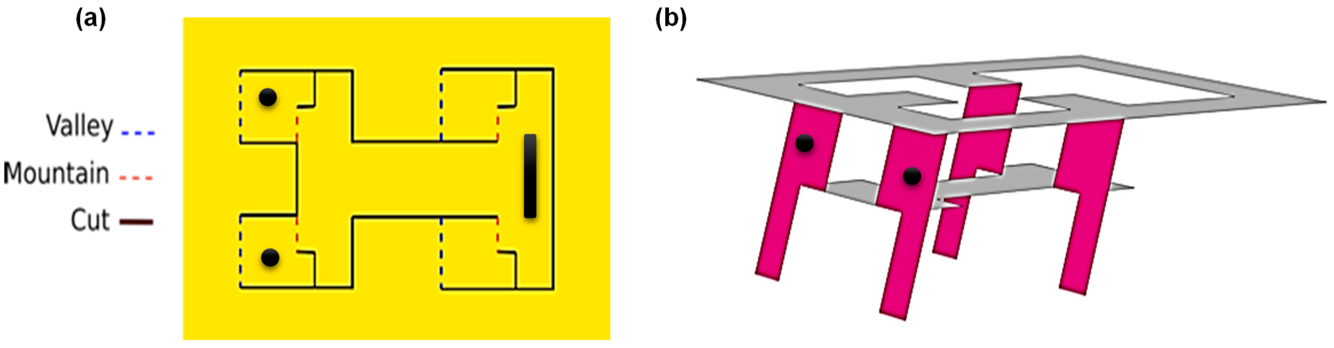
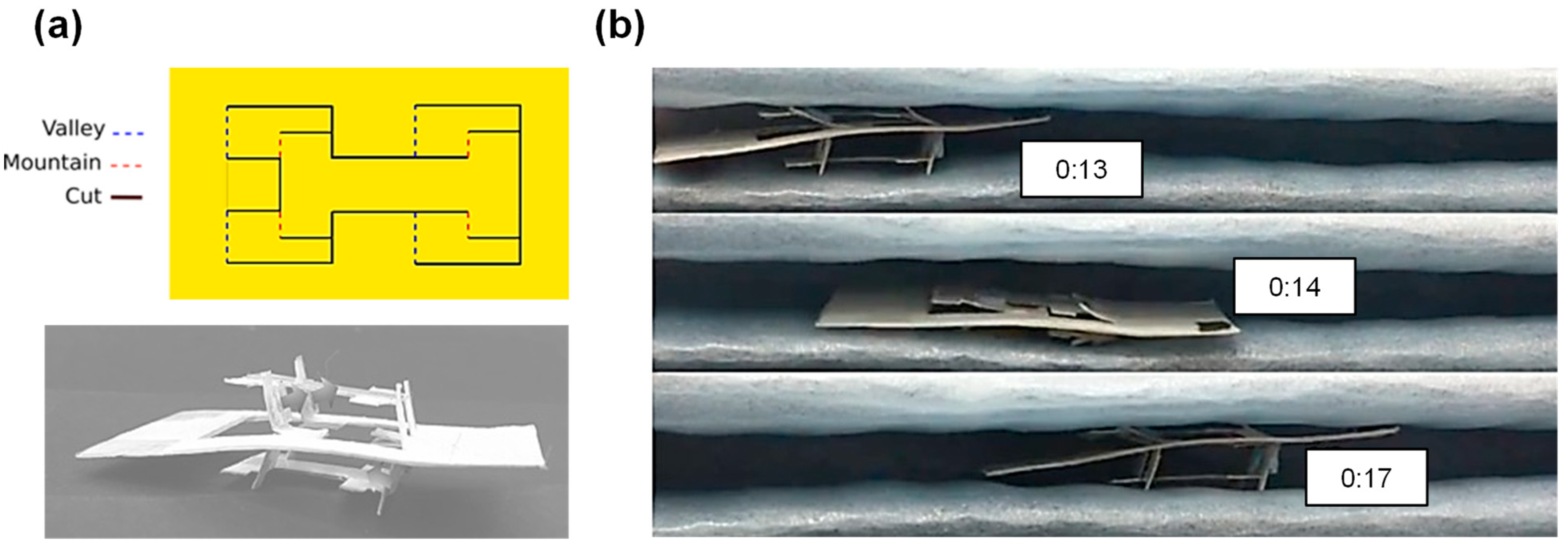
2.1. Origami and Kirigami for LEM

Incorporating origami and kirigami techniques in the design of flexible robotic structures has certain advantages such as compliance, lightweight, and ease of manufacturing [9,20]. Terrestrial worm robots often modulate the friction between their bodies and the traveling surface for movement. Manipulating the friction coefficients of different parts of the robot can enable them to carry out friction-based movements such as stick-slip mechanism [6,33], or frictional anisotropy with directional friction [34,35]. A higher coefficient of friction results in higher frictional force between the robot and the surface. Kirigami skin can be utilized to provide the necessary frictional properties. In this paper, we study origami and kirigami structures because they can potentially provide large deformation and modulate mechanical properties [36]. Different techniques such as creasing or cutting can largely vary the ability to change shapes, extend, and rotate the structures, all of which can be largely applicable in the design of LEMs, which will be elaborated further in Section 2.4.

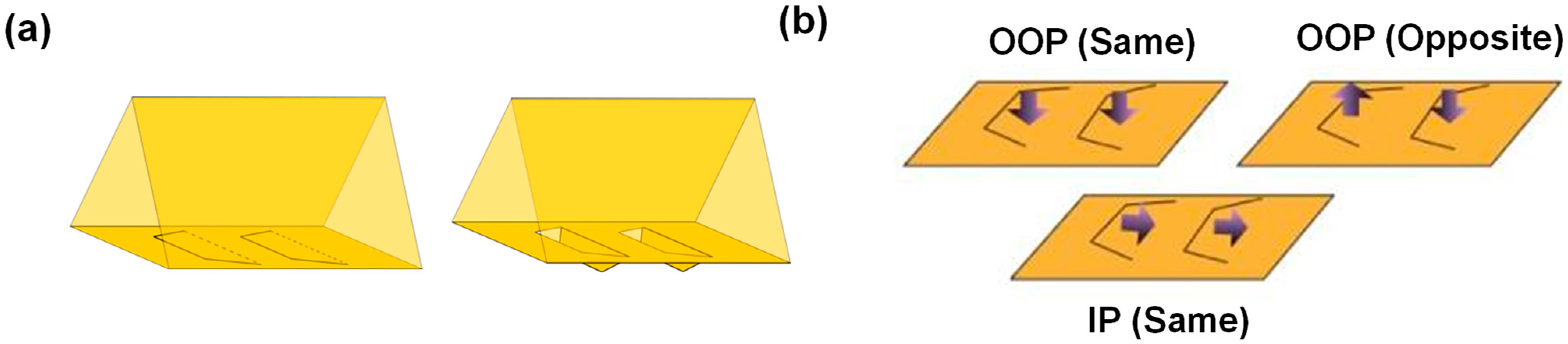
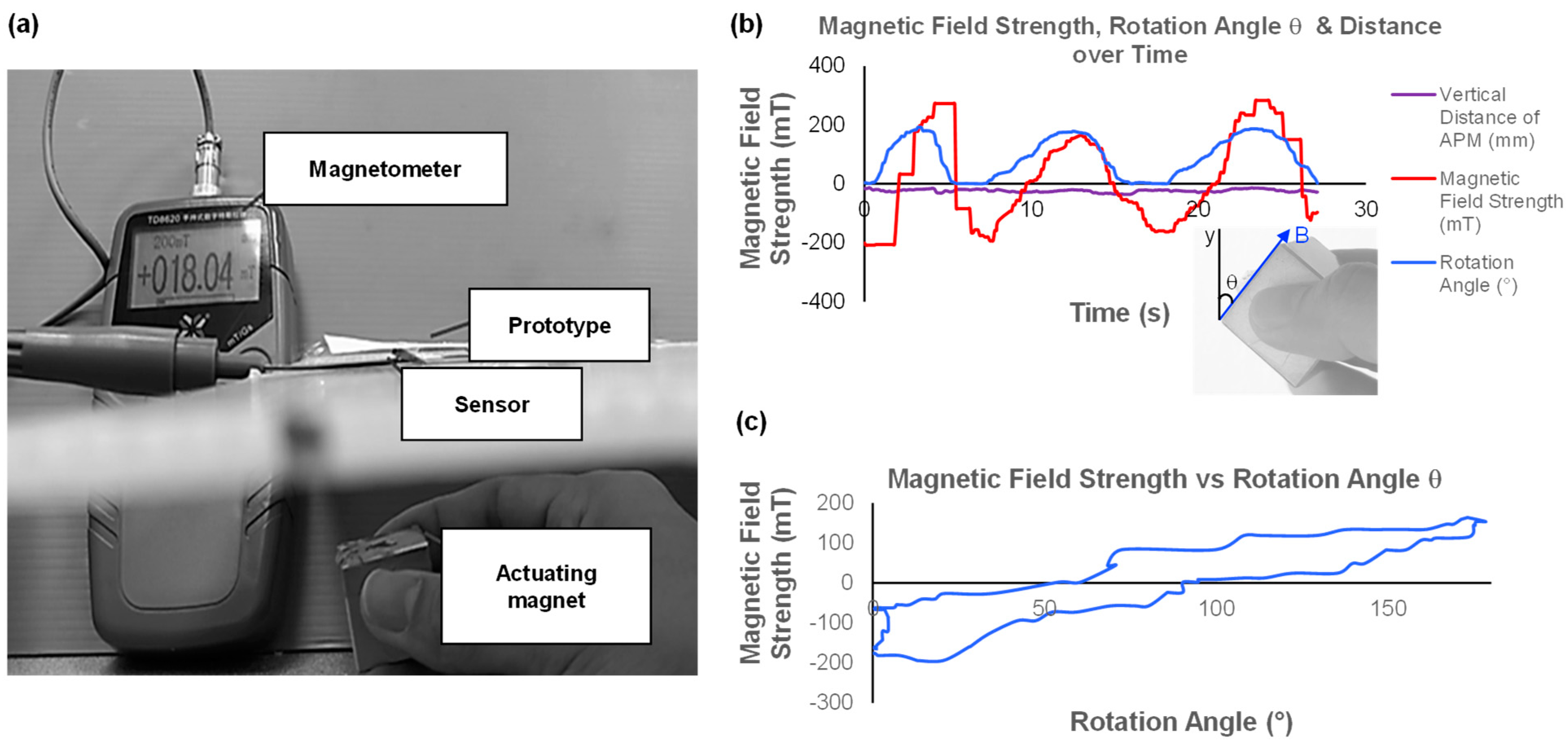
2.2. Magnetic Actuation

The magnetic field has advantages over other actuating fields such as electrical, optical, or acoustics in tetherless manipulating forces and torques [37] to control the translational and rotational motions. Magnetic actuation includes actuation by using permanent magnets or electromagnets. While electromagnetic actuation provides highly precise control of a magnetic object, they are expensive and require a large workspace. Hence, we chose to use permanent magnets in this paper due to their simplicity at this initial research stage. Manual manipulation of the actuating permanent magnet (APM) is used to control and modulate the direction and strength of the induced magnetic field during the actuation of the robot prototypes.
The principle of this method relies on manipulating the magnetic field acting on magnetized objects. When a magnetized object enters a magnetic field exerted by an APM, magnetic forces and torques are exerted on the magnetized object. Magnetic torque causes the object to rotate to align to the magnetic dipole of the actuating magnetic field. According to [38], the magnetic torque and force can be expressed as:
τm = M × B
fm = (M·▽)B
where τm is the magnetic torque; fm is the magnetic force; M is the total dipole moment of the magnetized object (A/m); and B is the flux density of the magnetic field (T) applied by the APM.
This paper uses ferromagnetic materials (permanent neodymium magnets) as both the APM and the actuated components (internal magnets). We will design LEM prototypes with legs/flaps-like components to attach small neodymium magnets (internal permanent magnets, IPM). Then, we manually control the APM to generate the desirable torque and, consequently, the LEM robot’s motion. One of the goals of this paper is to produce repeatable motion patterns using this actuation method.

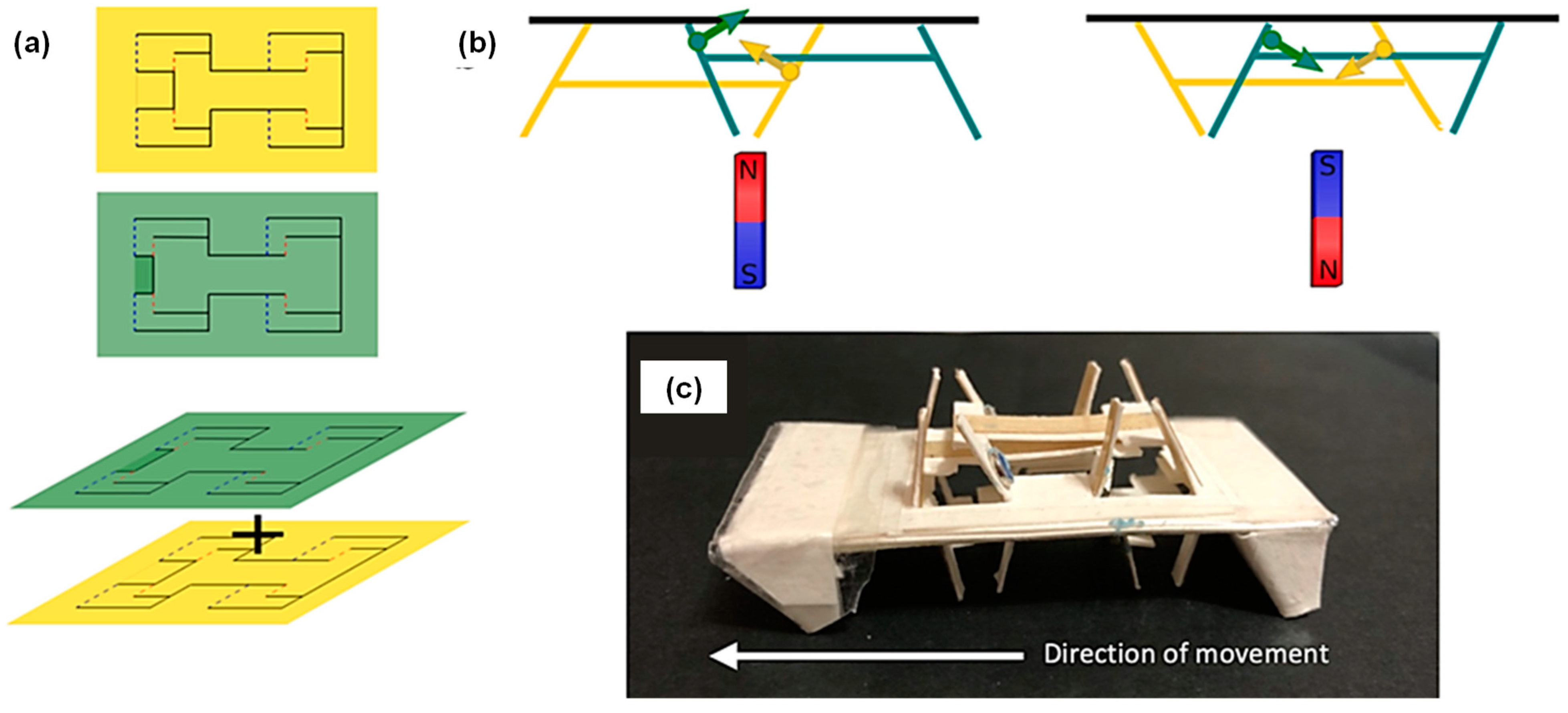
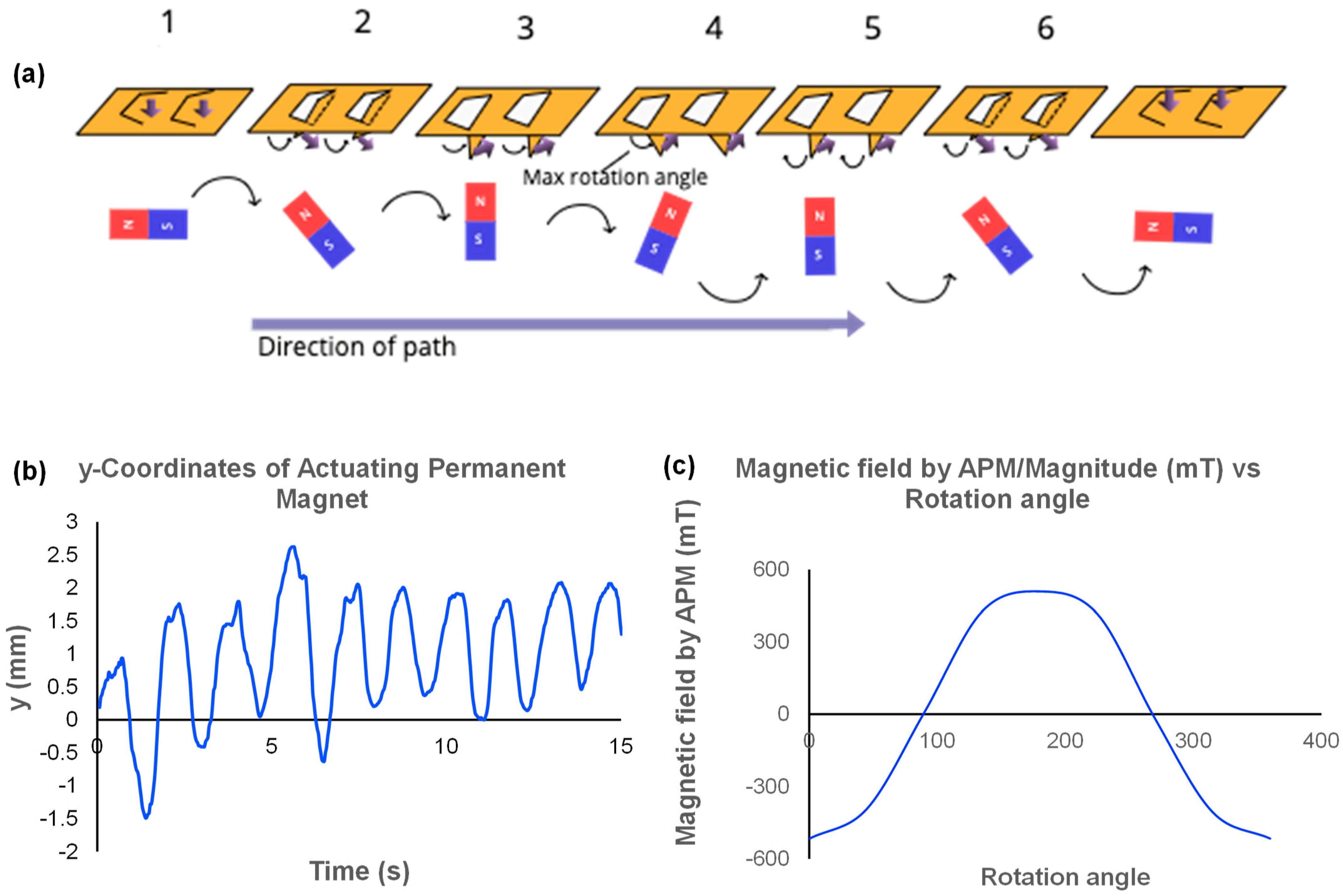
2.3. Locomotion Mechanism

The basic locomotion mechanism employed by the majority of the LEM prototypes in this paper is the friction-based stick-slip motion which relies on the induced magnetic torque from the APM to rotate the “legs” or “flaps.” Friction-based movements mimic the natural locomotion using properties such as frictional anisotropy [22,39,40], which can propel the object forward while preventing back-slippage [41]. The basic design of this mechanism includes the use of flaps located on the side that is in contact with the travelling surface. These flaps are attached with small permanent magnets (diameter 5 mm, thickness 1 mm). When influenced by a magnetic field applied by a stronger and larger permanent magnet of size 25 mm × 25 mm × 25 mm, these small internal magnets will rotate, consequently inducing the flaps they are attached on to move in a fashion that propels the structure forward. As a proof of concept, a simple triangular prism design made of paper was fabricated to incorporate a base (21 mm × 21 mm) with trapezoidal flaps attached with IPMs (Figure 1a). Flaps of length 4 mm are cut into trapezoidal shapes based on their relatively more efficient performance in a pneumatic actuated kirigami snake paper [34]. Several magnetization direction combinations and magnet types were tested to compare and determine the characteristics of the movement (Figure 1b). The out-of-plane (OOP) direction represents the orthogonal direction with respect to the flap on which the magnet is placed, while the in-plane (IP) direction represents parallel magnetization with the flap. IPMs are attached to the flaps by either adhesive tape. These different placements of magnetization directions are tested and compared, as shown in Table 2.
An alternative to attaching tiny rigid magnets to the flaps is to coat magnetorheological elastomer (MRE) onto the flaps. This approach also allows us to modify the strength and orientation of magnetization. Using MRE, we can fabricate various customizable domains that can create more versatile movements, allowing us to customize the material with non-uniform magnetization directions if needed. MRE sheets can be fabricated by mixing ecoflex (or polydimethylsiloxane) and neodymium powder in the ratio of 1:4 and letting the mixture cure. The fabricated sheet has soft, elastic properties and can be magnetized and set in the desired polarity by placing it in suitable configurations under the influence of a strong magnetic field. In general, thicker MRE sheets contain a greater density of magnetic particles and can provide greater magnetic torque when stimulated by the same external magnetic field, which helps to prop up the body and propel the mechanism more significantly than thinner MRE sheets.
Table 2 compares the different combinations of magnet types and magnetization direction. As the flaps rotate and push the prism base up from the ground, we observe that the prism is vulnerable to flipping in response to the strong magnetic torque. Hence, anchoring using additional soft magnets on the base is required, as soft magnets are attracted to the APM regardless of its orientation. We chose to use IPMs instead of MRE sheets for the rest of the paper due to the stronger magnetic field interactions and ease of integration.

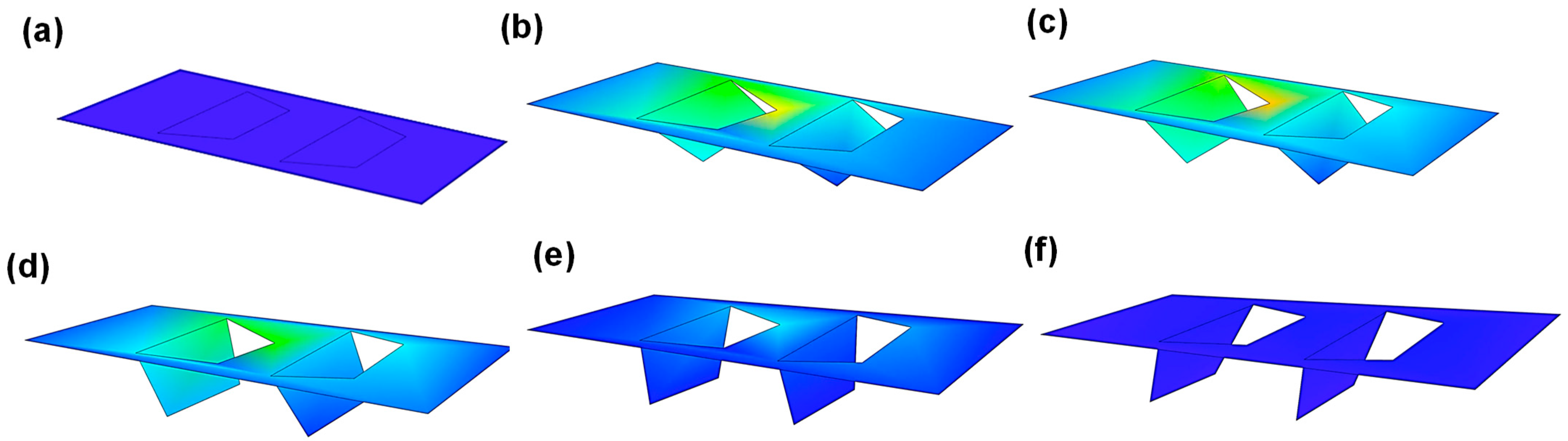
2.4. Lamina Emergent Mechanism

Lamina Emergent Mechanisms (LEMs) are mechanisms designed from planar material capable of out-of-plane motions. LEM can be advantageous in carrying out complicated mechanical tasks in constrained environments due to its compact design [42].
Using this concept and the crawling mechanism mentioned above, a design was created that involves pairs of legs (attached with IPMs) coupled with one another that can rotate simultaneously out of the lamina plane. Additional anchoring is provided with a soft magnet at the rear end of the LEM to prevent flipping and provide more stable forward locomotion. Each pair of legs has a size of 14 mm × 21 mm (L × W), leg length of 10 mm, leg width of 7 mm, and foot-to-foot spacing of 21 mm. The prototype of a single layer of LEM (SLEM) is shown in Figure 2 (dimensions 65 mm × 35 mm).
We used 300 gsm paper to fabricate the structure body. As the stiffness of the paper tends to reduce the range of motion of its legs, we create partial cuts in the mountains or valleys folds of the crease pattern of the design [43,44] (Figure 2). The partial cut is placed on every the “mountain” edge of every fold to reduce restriction in folding.
However, we observed that the basic movement produced by the SLEM is still susceptible to flipping and backward slippage and has a limited locomotion style. Hence, we considered other designs of the SLEM structure. The next LEM structure, named Dual-Layer LEM (DLLEM), comprises two identical SLEM structures (Figure 3). Two sheets are pasted in an orientation that mirrors the other. We test the ability of the structure to crawl in a more confined environment (height 16 mm) where the robot can use both sides to create friction-based movement (Figure 3b). This DLLEM structure is also made of 300 gsm paper and has its feet and “spine” (the central part that connects all pairs of legs) reinforced by plastic sheets to reduce wear and tear. Two pairs of small neodymium disc magnets are attached to two different pairs of legs, each on one side of the structure. This way, both pairs of magnets can simultaneously rotate and pop up the structure’s legs at the same time when a magnetic field is applied. The structure is placed between two styrofoam sheets to mimic surrounding frictional surfaces that can also prevent flipping or rotation of the body. Limitations of this mechanism include stability and the ability to only crawl in more confined environments. Given that the robot moves based on the simultaneous rotation of parallel pairs of legs (coupling), it affects the independent motion of each pair of legs. This may limit the dynamic freedom of each leg during motion and, therefore, might be less flexible and unable to overcome obstacles and traverse more challenging terrains.
To overcome the limitations observed in the DDLEM design, we modified the LEM by assembling two layers of SLEM per side (for a total of four SLEM sheets) as shown in Figure 4. The dimensions of certain parts of the SLEM design were modified to fit one SLEM sheet inside the other to act as opposite-moving pairs of legs. We name the mechanism Alternating Mirror Direction LEM (AMDLEM) due to the opposite mirror direction in which the structure legs on one SLEM sheet move with respect to those on the other SLEM. To achieve directional movement, legs with fixed directions are added to the AMDLEM to allow greater backward friction and easier forward slip. Several studies have incorporated similar methods, such as incorporating steel hooks [45] or directional feet [8] that point toward the back of the structure (away from the direction of movement).

3. Results

In this section, we report the results of the experiments we conduct to characterize the stick-slip locomotion of the LEM prototypes fabricated (triangular prism, SLEM, AMDLEM).
Measurement of the variation in magnetic field strength created by the APM when actuating the LEMs was carried out with the following set-up: TD8620 Magnetometer with the sensor placed right under the SLEM structure at the actuation point, providing magnetic field strength readings when the APM is manually rotated. Displacement graphs are generated using the Physics Tracker software, which tracks one chosen point on the prototypes over time.
We first aim to establish and confirm the relationship between the APM and the response of legs with the attached IPM (Figure 5). We observed that the peaks and troughs of the magnetic field strength correspond to the largest and smallest rotation angle of the APM with respect to the vertical direction. The magnet is placed directly below the sensor’s tip to measure the direct magnetic field strength created by the APM. To control and actuate the robot in real time, the APM is placed below the LEM robots and is moved according to the position of the IPMs on the structure.

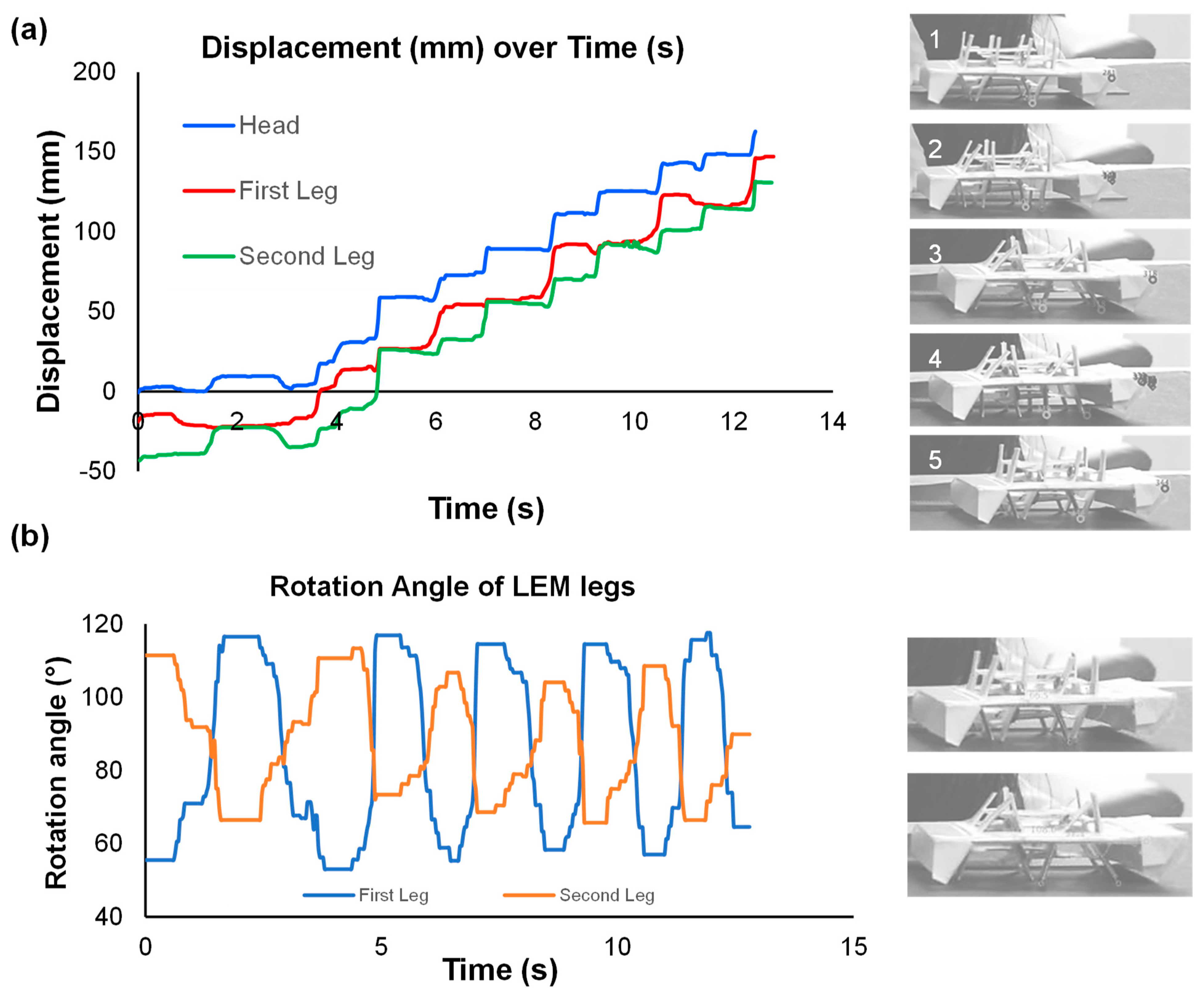
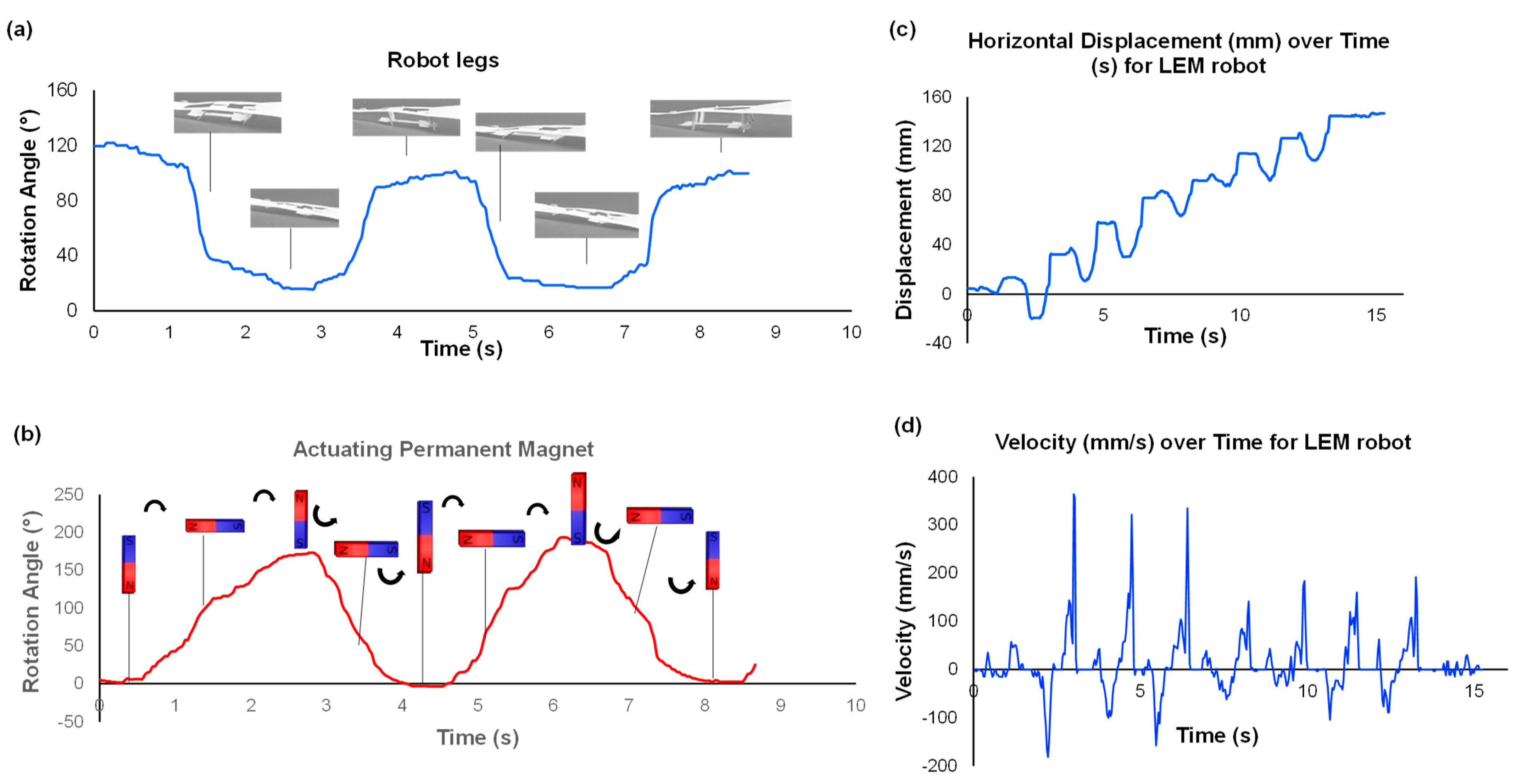
3.1. Relationship between Leg Locomotion and Actuating Magnet

A movement cycle can be split into six phases, as seen in Figure 6, in which the purple arrows indicate the direction of magnetization of the mechanism flaps, and the black arrows indicate the direction of rotation.
Firstly, the trapezoidal flaps on the mechanism remain in-plane with respect to the mechanism’s base. When the APM rotates clockwise, it exerts a magnetic torque that repels the IPM on the flaps, causing the flaps to rotate anticlockwise and become vertical at phase 3. When the APM continue to rotate beyond 90°, the rotation of the flap extends to more than 90° with respect to the horizontal plane. The maximum rotation angle is achieved in phase 4, providing an optimum contact point and acting as a hinge for the forward propelling motion in phases 5 and 6. Displacement will be seen in phases 5 and 6. Figure 6b represents the sinusoidal rotation of the actuating magnet in terms of y-coordinates, which takes approximately 14 s to complete nine cycles.
Amanda Ghassei [46] developed an origami simulator to simulate the folding of the designs presented in this paper, where the strain visualization was generated by adjusting the folding parameters. Designs follow the predetermined set of rules by the simulator, where certain line colors and line opacity indicate the direction of folds (valley and mountain) and the extent of folding (opacity), respectively. The parameters defined were axial stiffness, face stiffness, fold stiffness, facet crease stiffness, damping ratio, and maximum strain level allowed by the material. Figure 7 shows the strain visualization of the base design of the triangular prism mechanism when the flaps rotate outward. The parameters are set at maximum, with the maximum strain level set at 1%. Due to the simple arrangement of the creases on the design, the folds are easily achieved and do not result in significant strain.
Strain analysis was also carried out on the base design of the LEM mechanism. Figure 8 shows that increasing the facet crease stiffness results in increased structural rigidity and strength of the material and a decrease in the strain level at the joints. Parameter values used in the simulator remain constant: max strain value 5%, maximum axial stiffness, face stiffness, fold stiffness, and damping ratio. The facet crease stiffness results are adjusted to the following values: (a) 0.2, (b) 1, (c) 3 (maximum value). In real-life applications, facet crease stiffness can be increased by reinforcing the legs and body with plastic material, making the structure sturdier and subjected to less strain, as in the later versions of the SLEM, DDLEM, and AMDLEM. We can also reduce the maximum strain value in order for better visualization of the stress points, as shown in Figure 9.

3.2. Triangular Prism Locomotion

During the actuation of the triangular prism, we observed that as the flaps pop up, the prism body tends to rotate slightly anticlockwise, resulting in backwards horizontal displacement of the mechanism’s tip.
In general, the prism takes around 22 gait cycles, equivalent to 35 s, to complete the course of 15 cm (≈4.3 mm/s), as shown in Figure 10. Then, we generate a velocity graph from the same data and calculate the maximum instantaneous velocity reached in a forward movement to be 352 mm/s.

3.3. SLEM Locomotion

We actuated the SLEM robot at 0.6 Hz and track the movements of the robot’s legs over time. (Figure 11). Due to the flexible material that makes up the body of the SLEM, we observed that the head of the SLEM tends to bend back significantly during phase 3 (Figure 6a) of its gait cycle, which due to its long body produces a much larger step size than that of the triangular prism. This SLEM only needs to complete eight gait cycles (corresponding to ≈14 s) at the actuation frequency of 0.6 Hz to cover a distance of 15.0 cm (≈10.7 mm/s), reaching a maximum instantaneous velocity of 363.8 mm/s, compared to 22 gait cycles by the triangular prism.

3.4. AMDLEM Locomotion

As compared to the SLEM, the additional modification brought about by the opposite movement of the pairs of legs and the fixed direction legs for the increased directional friction has reduced the backward slippage of the mechanism. Figure 12 shows the displacement in the x-direction of the LEM mechanism with much less backward motion than the SLEM design. The AMDLEM prototype completes the distance of 15 cm in 12 s, taking 5 cycles to complete (≈12.5 mm/s). Due to the larger step size of the mechanism coupled with minimal backward slippage, the overall movement of the mechanism is effective, achieving the highest locomotion speed among the three LEM prototypes. However, undesirable dragging or sliding due to magnet attraction is observed despite the improved performance.

4. Discussion

The mechanism designs presented in this paper have similar displacement–time graphs due to their similar locomotion mechanism. For all three designs, the actuation frequency was approximately 0.6 Hz. However, as actuation was manually carried out, the exact actuation frequency is not constantly 0.6 Hz and therefore could have affected the movement of the mechanisms. In addition, the pulling force exerted by the actuating magnet on the mechanism during movement is inevitable. If the actuating magnet moves too fast toward the end line, the mechanism will slip forward when dragged, making the result biased. In this section, we further explore how changing different parameters (actuation frequency, friction, leg length, stiffness, and compressibility) affects the locomotion of the mechanism.

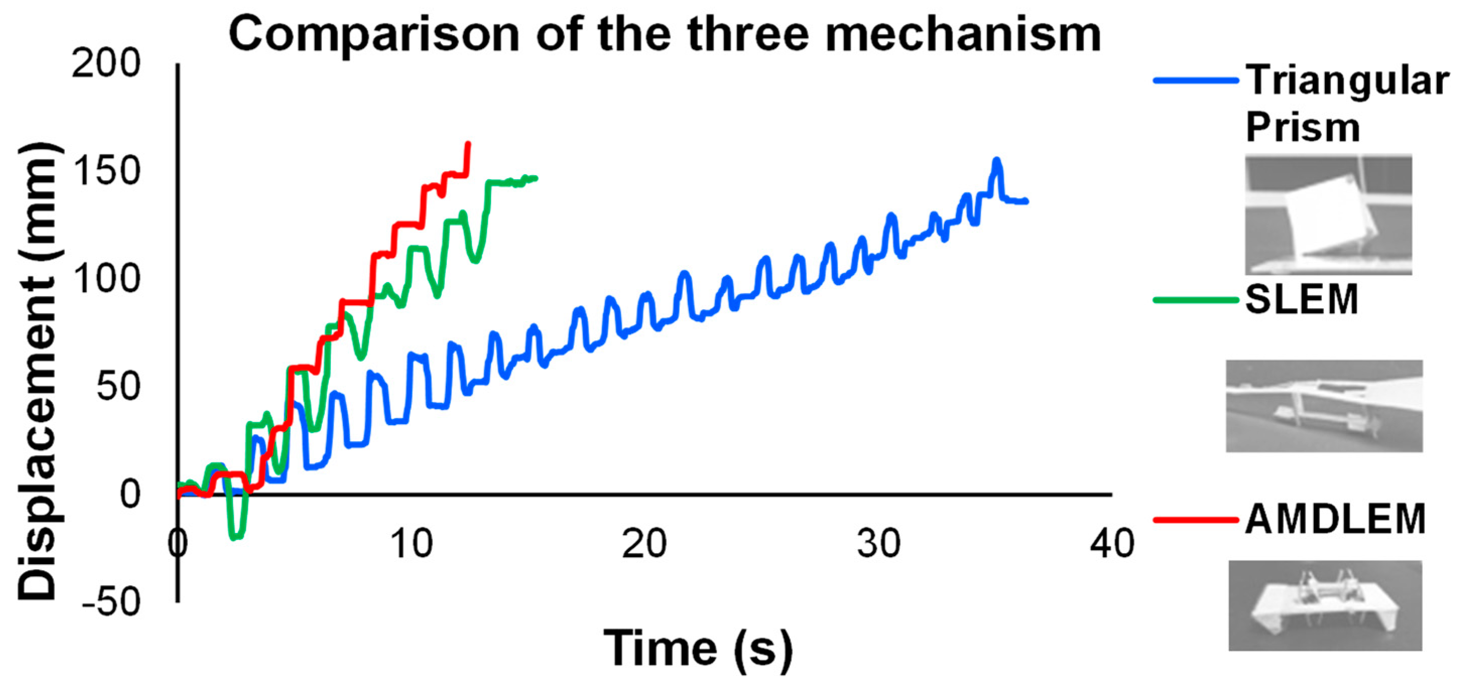
4.1. Comparison of Triangular Prism, SLEM, and AMDLEM Locomotion

The displacement–time graphs of the three mechanisms are compared in Figure 13. The average step sizes are calculated at different actuation frequencies based on the step size. The flexible and long body of the LEM mechanisms allows them to have a larger step size of 17.7 mm (for SLEM) and 29.62 mm (for AMDLEM). However, due to the less thick and stiff body of the SLEM, the step sizes vary much more significantly at different actuating frequencies, as seen in the larger standard deviation (SD) of 2.47. The alternating legs of AMDLEM allow this mechanism to have the greatest speed and step size relative to its leg length. Other mechanisms are more stable with shorter average step sizes and smaller SD.
Table 3 shows a compilation of the attributes of the mechanism designs, and their average step sizes are calculated based on the step size at different actuation frequencies. The flexible and long body of the LEM mechanisms allows them to have a large step size of 17.7 mm (for SLEM) and 29.62 mm (for AMDLEM) and average velocity of 10.8 mm/s and 12.4 mm/s. However, due to the soft and long body of SLEM, the step sizes vary much more significantly at different actuating frequencies, as seen in the larger standard deviation (SD) of 2.47. The alternating legs of AMDLEM allow the mechanism to have the greatest speed and step size relative to its leg length. Other mechanisms are more stable with shorter average step sizes and smaller SD. From examining several types of animals, the ratio between the length of legs (L) and spacing between feet (S) can affect the ability to locomote and support the body. A larger L/S ratio allows for more efficient locomotion, while a lower L/S provides better support [32].

4.2. Effect of Actuation Frequency on Speed of SLEM Robot

We observe a positive relationship between the speeds of the SLEM mechanism at different actuation frequencies (Figure 14). Due to the mechanisms being manually actuated, human errors are likely to happen, and higher or lower frequencies were not tested due to the limitations of manual actuation. Hence, this linear relationship might change at very low or very high frequency [47].

4.3. Effect of Friction

Friction plays an important role in the movement of the presented mechanism prototypes as the mechanism is friction-based. As backward slippage can be observed in all prototypes, constraints regarding suitable movement surfaces can be introduced to observe the desired locomotion. Various surfaces are tested with the SLEM mechanism (10 mm leg length) to calculate the coefficient of static friction (μ) between the surfaces (Figure 15). The SLEM mechanism is placed on a horizontal platform lined with the chosen material for a sliding test in a popped-up configuration with legs perpendicular to the surface at the start of the test. The platform is raised to an incline until the SLEM mechanism starts sliding. The angle θ is recorded, and the coefficient of friction is calculated by tan(θ).
The movements of the SLEM on various surfaces are also recorded to compare their speeds. Due to the different frictional properties of these surfaces and the human error in manual actuation, actuation frequencies are not identical. For instance, the bubble wrap has an irregular surface, and due to its bumpiness, it is impossible to provide a high actuation frequency without flipping or steering the mechanism in an unwanted fashion. From Table 4, the low friction paper surface allows for more sliding and, therefore, higher stride length and speed. The foam material provides higher friction, allowing for a longer stride length. For significantly higher friction materials—bubble wrap and towel, the SLEM mechanism is observed to have shorter stride length and hence require more gait cycles to complete, as it tends to be stuck or hindered by the irregularities on the surface. Hence, it can be shown that the current SLEM works best on a slightly frictional surface without noticeable irregularities without meeting problems of uncontrolled steering or flipping.
Using the same materials, the coefficient of friction for the improved AMDLEM can be calculated to compare the backward (μb corresponding to θb) and forward friction coefficients (μf corresponding to θf). The directional feet provide anisotropic friction, with higher backward friction than forward friction. Table 5 shows that the directional feet only slightly increase the backward friction for paper and foam. It can be observed that the higher friction surfaces of bubble wrap and towel provide better anisotropic friction for the AMDLEM mechanism (θb equals 4.47 and 1.74 times θf). Further trials of other directional feet can be carried out to improve the directional frictional properties.

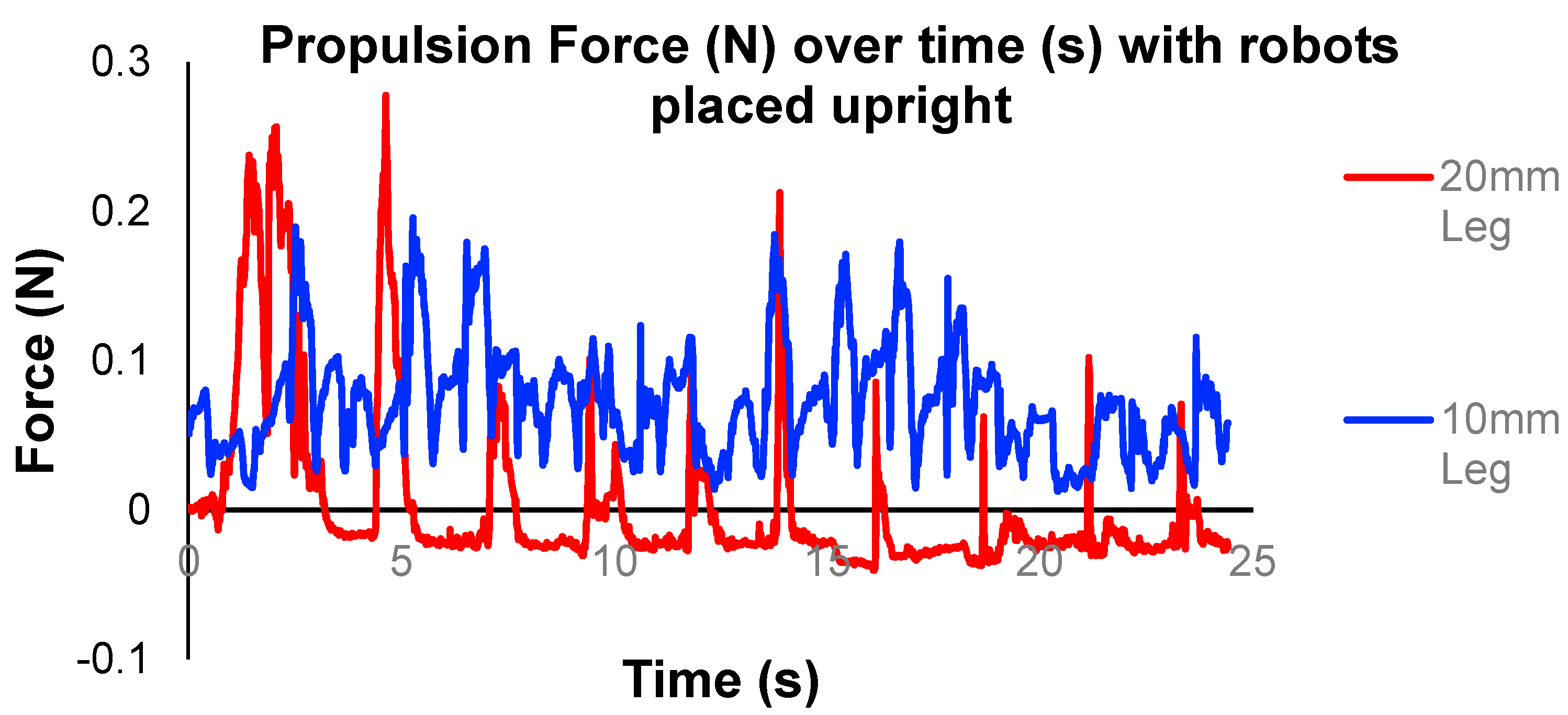
4.4. Effect of Leg Length

As longer leg lengths can potentially propel the structure body further forward, testing was carried out to determine the effects of LEM leg length on its movement (Figure 16). An SLEM design with a leg length of 20 mm (named SLEM-20) is created to compare against the original 10 mm SLEM leg length (named SLEM-10). A force sensor F/T Sensor: Nano17 (ATI Industrial Automation) is attached to the SLEMs via a copper string. When the structure moves forward, it pulls on the string, and the force values are recorded in the ATI software. Propulsion forces are measured, and the average peak force was calculated for the two different types of structure base materials (300 gsm paper vs. 70 gsm paper), two different leg lengths (20 mm vs. 10 mm) and measured at two different points on the structure (tail vs. leg), as summarized in Table 6.
Table 6 shows that the propulsion force measured at the tail is generally lower than that at the leg, as the leg is the main actuated component of the structure. Using thinner materials to fabricate the LEM results in more flexibility and therefore a larger range of motion, allowing for slightly greater propulsion force. The SLEM-20 is shown to generate greater propulsion force.
Figure 17 shows the propulsion force measured for the repeated movement of the SLEM when it is in its normal upright position and secured onto the horizontal plane upside down. The upside-down SLEM is taped to the horizontal platform with its leg attached to the sensor. Hence, the force measured is more stable and solely as a result of magnetic actuation. It does not have to account for balancing and propelling the SLEM forward. We observed that the propulsion force generated by the SLEM-10 is generally higher than the force generated by SLEM-20. This could be explained by the closer distance of the IPM to the APM on the 10 mm leg when upside down compared to that on the 20 mm leg. There are a total of 18 cycles completed within 25 s by the SLEM-10, which is 1.8 times greater than the 10 cycles completed by the SLEM-20. The faster rotation also results in higher acceleration, thus resulting in a higher pulling force on the sensor. In Figure 17 we can see that the propulsion force peaks at 0.28 N for the SLEM-20 compared to 0.20 N for the SLEM-10. However, due to the greater leg length, the movement is much more unstable, as seen in the greater fluctuation of propulsion force by the 20 mm leg. The shorter leg length of 10 mm provides more stable and consistent propulsion forces with higher rotation frequency. Hence, we conclude that the higher the leg length, the further the IPMs are away from the APM, which leads to a lower controllability and stability of the structure, despite the potentially higher propulsion force and stride length.

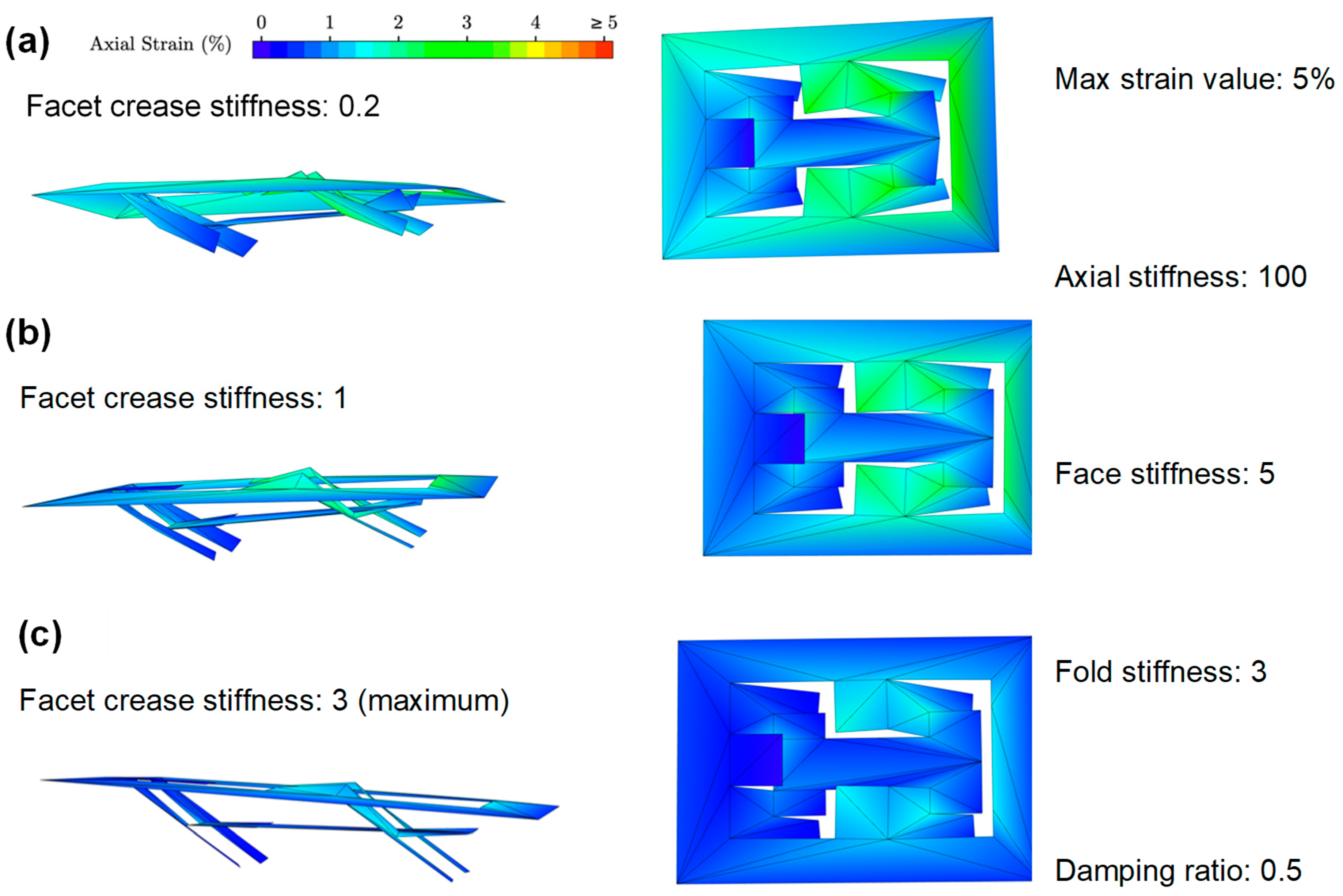
4.5. Stiffness of Structure

The AMDLEM was created with legs on both sides to provide propulsion from the walls on top and below the structure. However, when placing the structure in a confined environment, its rigid body and legs experience difficulty in moving swiftly forward. Hence, coating softer materials such as silicon at the tip of the legs may improve the interaction between the robot with the surroundings to enable it to squeeze or glide through obstacles more easily.

4.6. Compressibility and Load-Bearing Capability

The LEM structure in neutral position is planar, meaning that it can be compressed in height and has the potential to travel through crevices with narrow heights. Currently, the mechanisms have stiff bodies and legs that may hinder the mechanism from generating more flexible movements. We can also add loads to test for the strength and load-bearing capability of the mechanism.

5. Conclusions

In this work, we designed and fabricated three LEM designs (triangular prism, SLEM, and AMDLEM) capable of generating biomimetic stick-slip locomotion. Among the three fabricated prototypes, the AMDLEM has the greatest speed and overall locomotion efficiency due to its long step length and added directional friction, which proves the effectiveness of additional features such as directional feet in providing anisotropic friction.
While the AMDLEM exhibits anisotropic friction, it is not significant enough to prevent sliding and backward slippage. Hence, further experiments and improvement in increasing the stability and frictional anisotropy of this mechanism need to be done to reduce unwanted backward rotation of the body and improve movement efficiency. One way is to use other materials to create fixed-direction feet such as silicone or steel hooks.
Current designs have simple combinations of neodymium magnets, and thus, magnetic coupling is inevitable. The interaction between magnets in the structure can be further studied and experimented with, taking advantage of this coupling. For example, the DLLEM with a dual layer is observed to make slight turns when introduced to a vertical magnetic field from the actuating magnet, while the singular layer of LEM in the SLEM does not. Studying the interaction between magnets will allow better locomotion methods that can carry out more complicated tasks such as turning, jumping, and swimming.

Author Contributions

H.R. and T.N.L.G.: Conceptualization, methodology; C.J.C., G.P. and H.R.: validation, formal analysis, writing—original draft preparation, review and editing. All authors have read and agreed to the published version of the manuscript.

Funding

This work was supported by Chinese University of Hong Kong (CUHK) Direct Grant (4055139) for research project on Multiphysics Study of Magnetically Deployable Robotic Collapsible Structures.

Institutional Review Board Statement

Not applicable.

Informed Consent Statement

Not applicable.

Data Availability Statement

Not applicable.

Conflicts of Interest

The authors declare no conflict of interest. The funders had no role in the design of the study; in the collection, analyses, or interpretation of data; in the writing of the manuscript, or in the decision to publish the results.

References

  1. Kim, S.; Laschi, C.; Trimmer, B. Soft robotics: A bioinspired evolution in robotics. Trends Biotechnol. 2013, 31, 287–294. [Google Scholar] [CrossRef]
  2. Cao, Y.; Liu, Y.; Chen, Y.; Zhu, L.; Yan, Y.; Chen, X. A novel slithering locomotion mechanism for a snake-like soft robot. J. Mech. Phys. Solids 2017, 99, 304–320. [Google Scholar] [CrossRef]
  3. Rus, D.; Tolley, M.T. Design, fabrication and control of soft robots. Nature 2015, 521, 467–475. [Google Scholar] [CrossRef] [Green Version]
  4. Seok, S.; Onal, C.D.; Wood, R.; Rus, D.; Kim, S. Peristaltic locomotion with antagonistic actuators in soft robotics. In Proceedings of the 2010 IEEE International Conference on Robotics and Automation, Anchorage, AK, USA, 3–7 May 2010; pp. 1228–1233. [Google Scholar] [CrossRef]
  5. Shian, S.; Bertoldi, K.; Clarke, D.R. Dielectric Elastomer Based ‘Grippers’ for Soft Robotics. Adv. Mater. 2015, 27, 6814–6819. [Google Scholar] [CrossRef]
  6. Wang, W.; Lee, J.-Y.; Rodrigue, H.; Song, S.-H.; Chu, W.-S.; Ahn, S.-H. Locomotion of inchworm-inspired robot made of smart soft composite (SSC). Bioinspir. Biomim. 2014, 9, 046006. [Google Scholar] [CrossRef]
  7. Seok, S.; Onal, C.D.; Cho, K.; Wood, R.J.; Rus, D.; Kim, S. Meshworm: A Peristaltic Soft Robot With Antagonistic Nickel Titanium Coil Actuators. IEEE/ASME Trans. Mechatron. 2013, 18, 1485–1497. [Google Scholar] [CrossRef]
  8. Onal, C.D.; Wood, R.J.; Rus, D. An Origami-Inspired Approach to Worm Robots. IEEE/ASME Trans. Mechatron. 2013, 18, 430–438. [Google Scholar] [CrossRef]
  9. Fang, H.; Zhang, Y.; Wang, K.W. Origami-based earthworm-like locomotion robots. Bioinspir. Biomim. 2017, 12, 065003. [Google Scholar] [CrossRef] [PubMed]
  10. Lin, H.-T.; Leisk, G.G.; Trimmer, B. GoQBot: A caterpillar-inspired soft-bodied rolling robot. Bioinspir. Biomim. 2011, 6, 026007. [Google Scholar] [CrossRef]
  11. Menciassi, D.A.; Gorini, S.; Dario, P. Development of a biomimetic miniature robotic crawler. Auton. Robots 2006, 21, 155–163. [Google Scholar] [CrossRef]
  12. Cianchetti, M.; Mattoli, V.; Mazzolai, B.; Laschi, C.; Dario, P. A new design methodology of electrostrictive actuators for bio-inspired robotics. Sens. Actuators B Chem. 2019, 142, 288–297. [Google Scholar] [CrossRef]
  13. O’Halloran, A.; O’Malley, F.; McHugh, P. A review on dielectric elastomer actuators, technology, applications, and challenges. J. Appl. Phys. 2008, 104, 071101. [Google Scholar] [CrossRef]
  14. Boyraz, P.; Runge, G.; Raatz, A. An Overview of Novel Actuators for Soft Robotics. Actuators 2018, 7, 48. [Google Scholar] [CrossRef] [Green Version]
  15. Jiang, S.; Feng, W.; Lou, J.; Yang, Z.; Liu, J.; Yang, J. Modelling and control of a five-degrees-of-freedom pneumatically actuated magnetic resonance-compatible robot. Int. J. Med. Robot. 2014, 10, 170–179. [Google Scholar] [CrossRef] [PubMed]
  16. Kim, Y.; Yuk, H.; Zhao, R.; Chester, S.A.; Zhao, X. Printing ferromagnetic domains for untethered fast-transforming soft materials. Nature 2018, 558, 274–279. [Google Scholar] [CrossRef] [PubMed]
  17. Song, C.-W.; Lee, D.-J.; Lee, S.-Y. Bioinspired Segment Robot with Earthworm-like Plane Locomotion. J. Bionic Eng. 2016, 13, 292–302. [Google Scholar] [CrossRef]
  18. Jang, B.; Nam, J.; Lee, W.; Jang, G. A Crawling Magnetic Robot Actuated and Steered via Oscillatory Rotating External Magnetic Fields in Tubular Environments. IEEE/ASME Trans. Mechatron. 2017, 22, 1465–1472. [Google Scholar] [CrossRef]
  19. Onal, C.D.; Rus, D. Autonomous undulatory serpentine locomotion utilizing body dynamics of a fluidic soft robot. Bioinspir. Biomim. 2013, 8, 026003. [Google Scholar] [CrossRef]
  20. Saito, T.; Kagiwada, T.; Harada, H. Development of an Earthworm Robot with a Shape Memory Alloy and Braided Tube. Adv. Robot. 2009, 23, 1743–1760. [Google Scholar] [CrossRef]
  21. Liu, B.; Ozkan-Aydin, Y.; Goldman, D.I.; Hammond, F.L. Kirigami skin improves soft earthworm robot anchoring and locomotion under cohesive soil. In Proceedings of the 2019 2nd IEEE International Conference on Soft Robotics (RoboSoft), Seoul, Korea, 14 April 2019; IEEE: Piscataway, NJ, USA, 2019; pp. 828–833. [Google Scholar]
  22. Ge, J.Z.; Calderón, A.A.; Chang, L.; Pérez-Arancibia, N.O. An earthworm-inspired friction-controlled soft robot capable of bidirectional locomotion. Bioinspir. Biomim. 2019, 14, 036004. [Google Scholar] [CrossRef]
  23. Jung, K.; Koo, J.C.; Nam, J.; Lee, Y.K.; Choi, H.R. Artificial annelid robot driven by soft actuators. Bioinspir. Biomim. 2007, 2, S42–S49. [Google Scholar] [CrossRef] [PubMed] [Green Version]
  24. Wang, K.; Yan, G.; Ma, G.; Ye, D. An Earthworm-Like Robotic Endoscope System for Human Intestine: Design, Analysis, and Experiment. Ann. Biomed. Eng. 2009, 37, 210–221. [Google Scholar] [CrossRef] [PubMed]
  25. Zuo, J.; Yan, G.; Gao, Z. A micro creeping robot for colonoscopy based on the earthworm. J. Med. Eng. Technol. 2005, 29, 1–7. [Google Scholar] [CrossRef]
  26. Manfredi, L.; Capoccia, E.; Ciuti, G.; Cuschier, A.I. A Soft Pneumatic Inchworm Double balloon (SPID) for colonoscopy. Sci. Rep. Nat. Publ. Group Lond. 2019, 9, 1–9. [Google Scholar] [CrossRef] [PubMed] [Green Version]
  27. Kim, S.H.; Hashi, S.; Ishiyama, K. Hybrid magnetic mechanism for active locomotion based on inchworm motion. Smart Mater. Struct. 2012, 22, 027001. [Google Scholar] [CrossRef]
  28. Lee, K.; Kim, Y.; Paik, J.K.; Shin, B. Clawed Miniature Inchworm Robot Driven by Electromagnetic Oscillatory Actuator. J. Bionic Eng. 2015, 12, 519–526. [Google Scholar] [CrossRef]
  29. Ito, T.; Ogushi, T.; Hayashi, T. Impulse-driven capsule by coil-induced magnetic field implementation. Mech. Mach. Theory 2010, 45, 1642–1650. [Google Scholar] [CrossRef]
  30. Min, H.-J.; Lim, H.-J.; Kim, S.H. A new impact actuator using linear momentum exchange of inertia mass. J. Med. Eng. Technol. 2002, 26, 265–269. [Google Scholar] [CrossRef]
  31. Hu, W.; Lum, G.Z.; Mastrangeli, M.; Sitti, M. Small-scale soft-bodied robot with multimodal locomotion. Nature 2018, 554, 81–85. [Google Scholar] [CrossRef]
  32. Lu, H.; Zhang, M.; Yang, Y.; Huang, Q. A bioinspired multi-legged soft millirobot that functions in both dry and wet conditions. Nat. Commun. Lond. 2018, 9, 3944. [Google Scholar] [CrossRef] [Green Version]
  33. Yesin, K.B.; Vollmers, K.; Nelson, B.J. Modeling and Control of Untethered Biomicrorobots in a Fluidic Environment Using Electromagnetic Fields. J. Robot. Res. 2006, 25, 527–536. [Google Scholar] [CrossRef]
  34. Rafsanjani, Y.; Zhang, B.; Liu, S.; Rubinstein, M.; Bertoldi, K. Kirigami skins make a simple soft actuator crawl. Sci. Robot. 2018, 3, eaar7555. [Google Scholar] [CrossRef] [Green Version]
  35. Ge, J.Z.; Calderón, A.A.; Pérez-Arancibia, N.O. An earthworm-inspired soft crawling robot controlled by friction. In Proceedings of the 2017 IEEE International Conference on Robotics and Biomimetics (ROBIO), Parisian Macao, China, 5–8 December 2017; pp. 834–841. [Google Scholar] [CrossRef] [Green Version]
  36. Callens, S.J.P.; Zadpoor, A.A. From flat sheets to curved geometries: Origami and kirigami approaches. Mater. Today 2018, 21, 241–264. [Google Scholar] [CrossRef]
  37. Erb, R.M.; Martin, J.J.; Soheilian, R.; Pan, C.; Barber, J.R. Actuating Soft Matter with Magnetic Torque. Adv. Funct. Mater. 2016, 26, 3859–3880. [Google Scholar] [CrossRef]
  38. Xu, T.; Yu, J.; Yan, X.; Choi, H.; Zhang, L. Magnetic Actuation Based Motion Control for Microrobots: An Overview. Micromachines 2015, 6, 1346–1364. [Google Scholar] [CrossRef]
  39. Zhou, X.; Majidi, C.; O’Reilly, O.M. Energy efficiency in friction-based locomotion mechanisms for soft and hard robots: Slower can be faster. Nonlinear Dyn. 2014, 78, 2811–2821. [Google Scholar] [CrossRef] [Green Version]
  40. Marvi, H.; Cook, J.P.; Streator, J.L.; Hu, D.L. Snakes move their scales to increase friction. Biotribology 2016, 5, 52–60. [Google Scholar] [CrossRef] [Green Version]
  41. Marvi, H.; Han, Y.; Sitti, M. Actively controlled fibrillar friction surfaces. Appl. Phys. Lett. 2015, 106, 51602. [Google Scholar] [CrossRef] [Green Version]
  42. Jacobsen, J.O.; Winder, B.G.; Howell, L.L.; Magleby, S.P. Lamina Emergent Mechanisms and Their Basic Elements. J. Mech. Robot. 2010, 2, 011003. [Google Scholar] [CrossRef]
  43. Ma, R.; Wu, C.; Wang, Z.L.; Tsukruk, V.V. Pop-Up Conducting Large-Area Biographene Kirigami. ACS Nano 2018, 12, 9714–9720. [Google Scholar] [CrossRef] [PubMed]
  44. Chen, Y.; Peng, R.; You, Z. Origami of thick panels. Science 2015, 349, 396–400. [Google Scholar] [CrossRef] [PubMed] [Green Version]
  45. Li, T.; Zou, Z.; Mao, G.; Yang, X.; Liang, Y.; Li, C.; Qu, S.; Suo, Z.; Yang, W. Agile and Resilient Insect-Scale Robot. Soft Robot. 2019, 6, 133–141. [Google Scholar] [CrossRef] [PubMed]
  46. Origami Simulator. Available online: http://www.amandaghassaei.com/projects/origami_simulator/ (accessed on 7 May 2020).
  47. Miyashita, S.; Guitron, S.; Li, S.; Rus, D. Robotic metamorphosis by origami exoskeletons. Sci. Robot. 2017, 2, eaao4369. [Google Scholar] [CrossRef] [PubMed] [Green Version]
Figure 1. Proof of concept to verify locomotion mechanism design. (a) Design of triangular prism mechanism where the bases consist of trapezoid-shaped magnetic flaps that rotate out of the plane for locomotion. (left) Triangular prism mechanism in neutral position; (right) triangular prism mechanism in popped-up (actuated) position. (b) Different magnetization directions: OOP magnetization (same direction placement), OOP magnetization (opposite direction placement) and IP magnetization (same direction placement).
Applsci 12 00014 g001
Figure 2. SLEM: (a) Top–down view of SLEM base with mountain and valley folds represented by dotted lines, cuts represented by continuous black lines (leg length 10 mm). IPMs (black circles) are attached to the front legs, and soft magnet stripes attach to the tail for increased anchoring (leg length 10 mm). (b) Three-dimensional (3D) simulation of SLEM in the pop-up configuration (leg length 14 mm). When the SLEM is under the influence of a magnetic field, the legs pop up, thus pushing the SLEM body/base upward and forward (leg length 10 mm).
Applsci 12 00014 g002
Figure 3. DDLEM prototype. (a) Design of LEM with dual-layer (DLLEM) structure base. (Top) Crease pattern of the SLEM used, where dotted lines represent the mountain and valley folds, cuts are represented by continuous black lines. This LEM design has longer legs (14 mm) than the previous 10 mm SLEM. (Bottom) Prototype of DLLEM with dual pop-up surfaces. (b) Movement of DLLEM structure in a confined environment.
Applsci 12 00014 g003
Figure 4. AMDLEM with an assembly of four LEM sheets. (a) Design of the two LEM sheets that can be assembled to form one side of the AMDLEM. Dotted lines represent mountain and valley folds; continuous black lines represent cuts. (b) Side view of the assembled two SLEM sheets from (a) when under the influence of the magnetic field generated by the interactions between the APM and IPM. The dots and arrows indicate the position and dipole orientation of the attached IPM. There are two alternating configurations, where each configuration shows the leg pairs mirroring each other. (c) A prototype with two sides of dual SLEM sheets and directional feet.
Applsci 12 00014 g004
Figure 5. Using magnetometer to measure magnetic field strength. (a) The magnetometer sensor tip is placed on the testing surface with the actuating permanent magnet placed right below it and the SLEM structure right on top. (b) Magnetic field strength, rotation angle θ of magnetic field, and vertical distance of APM from sensor versus time. Rotation angle θ is measured regarding the direction of the magnetic field with respect to the vertical direction. The rotation occurs anticlockwise, and once the magnet and magnetic field are completely inverted (by 180°), the magnet is rotated clockwise to revert to its original position. (c) Magnetic field strength plotted against rotation angle of magnetic field for one cycle.
Applsci 12 00014 g005
Figure 6. Locomotion mechanism presented in this paper: (a) Basic locomotion mechanism using an APM, split into six phases. The mechanism base has trapezoidal flaps attached with internal permanent magnets (IPM) with the direction of magnetization indicated by the purple arrows. Rotation of APM triggers the IPM (and consequently the trapezoidal flaps) to rotate, propelling the mechanism forward. (b) Sinusoidal representation of the movement of actuating magnet at approximately 0.6 Hz. (c) Magnetic field strength B (mT) of APM measured against rotation angle of the APM, in which the rotation angle is set to be the vertical direction with the north pole facing the sensor.
Applsci 12 00014 g006
Figure 7. Strain visualization of the movement of triangular prism mechanism. (af) show changes in strain level versus time.
Applsci 12 00014 g007
Figure 8. Strain visualization (side view and top view) for SLEM design with increasing facet crease stiffness (the material’s stiffness regarding its predetermined plane). Increasing facet crease stiffness shows an increase in structural rigidity and strength of the material and a decrease in the strain level at joints. Parameter values in the online simulator remain constant: max strain value 5%, maximum axial stiffness, face stiffness, fold stiffness, and damping ratio. The facet crease stiffness values are adjusted to the following values: (a) 0.2, (b) 1, (c) 3.
Applsci 12 00014 g008
Figure 9. Top view strain visualization of SLEM structure with different maximum strain percentage values. The remaining parameters are kept constant at their maximum values: axial stiffness, fold stiffness, facet crease stiffness, damping ratio. Maximum strain allowed: (a) 5%, (b) 1%. Reducing maximum strain displays the strain distribution more clearly. Strain visualization allows us to see the high-stress/strain points to predict failure points. The red or orange areas are more likely to fail first due to wear and tear after repeated movements.
Applsci 12 00014 g009
Figure 10. Locomotion of triangular prism. (a) Graph of displacement (x-direction) versus time for one triangular prism mechanism prototype with out-of-plane magnetization and opposite direction magnet placement, actuated at 0.6 Hz, completing 15 cm in 35 s with 22 gait cycles. Movement of one cycle, represented by the purple section of part (a). (b) y vs. × coordinates for two cycles of motion of the triangular prism mechanism. (c) Graph of velocity (x-direction) (mm/s) versus time (s) of the same triangular prism mechanism.
Applsci 12 00014 g010
Figure 11. Locomotion of SLEM: (c) Graph of displacement (x-direction) versus time for SLEM at 0.6 Hz, completing 15 cm in 14 s within eight gait cycles. (a) Movement of SLEM for one cycle, corresponds with the numbered points. The rotation angle of the SLEM leg is measured with respect to the horizontal planar body (parallel to the traveling surface). (b) The rotation angle of the APM is measured with respect to its vertical direction (north pole facing up). The visual representation of the angles is shown in the attached pictures. SLEM legs are vertical when the APM is in their original vertical direction (north pole facing up). (c) Graph of displacement of SLEM over time. (d) Graph of the velocity of the SLEM (x-direction) over time.
Applsci 12 00014 g011
Figure 12. Locomotion of AMDLEM mechanism: (a) Displacement (mm) versus time (s) of the AMDLEM with alternating leg movement. Displacements of the alternating legs are recorded to show the alternating direction of movement. Overlapping regions can be seen in the displacement graph, representing the movement when the legs rotate toward each other and touch. (b) Graph of the rotation angle of 1st and 2nd legs shown in part (a) where the maximum value of the 1st leg and the minimum value of the 2nd leg corresponds with the overlapping regions of part (a), meaning the legs are touching.
Applsci 12 00014 g012
Figure 13. Horizontal displacement (mm) versus time (s) for different mechanism designs. The mechanisms generally have a similar actuation frequency at 0.6 Hz. However, the actual frequency might vary versus time due to the human error of manual actuation.
Applsci 12 00014 g013
Figure 14. Speed (mm/s) against actuation frequency (Hz) for SLEM.
Applsci 12 00014 g014
Figure 15. Frictional properties of SLEM mechanism: (a) Coefficient of static friction μ between SLEM and different surfaces. (b) Sliding test between SLEM mechanism and the frictional surface. Angle θ is recorded to calculate μ. Angle θ is the angle at which the SLEM mechanism starts sliding on the surface on which it is placed. LEM is placed in a popped-up configuration with legs perpendicular to the surface at the start of the test.
Applsci 12 00014 g015
Figure 16. Set-up of propulsion force measurement test using force sensor in the x-direction. A copper string is used to attach the structure to the tip of the force sensor. SLEM structure is actuated by the APM below the test surface. When the structure legs move forward, they pull on the copper string, and the computer monitor registers a propulsion force.
Applsci 12 00014 g016
Figure 17. Propulsion forces for repeated movement using SLEM-20 and SLEM-10. A copper string is attached to the legs. The 20 mm legs show greater propulsion forces but are much more unstable when placed upright than the 10 mm legs over repeated movement. The shorter 10 mm legs are also much easier to be actuated and therefore actuation frequency is higher, which might affect the value of force measured.
Applsci 12 00014 g017
Table 2. Combinations of magnets and magnetization direction and observations from their locomotion.
ComponentsLocomotion
Two permanent magnet discs on two flaps, OOP magnetization;
Same direction placement
Flaps move in sync to actuating magnet.
Able to locomote, unstable
Require soft magnet on the base as an anchor
Thick MRE sheets on two flaps, OOP magnetization;
Opposite direction placement
Flaps move out of sync
Able to locomote, more stable as one magnet moves the flap while the other magnet is attracted to the surface, providing anchoring.
Thin MRE sheet as the entire base with flapsFlips when actuated as it is not anchored.
Hard to control the direction
Thick MRE attached to only the flaps, OOP magnetization;
Same direction
Flaps move in sync to actuating magnet.
Able to locomote, unstable
Require soft magnet on the base as an anchor
Thick MRE attached to only the flaps, IP magnetization;
Same direction
Reacts most obviously to actuating magnetic field, compared to the rest
Flaps pop up straight when the actuating magnet is directly below → Could be unstable
Table 3. Types of mechanisms and their attributes and locomotion results showing locomotion efficiency.
Mechanism TypeBody Length (mm)Leg Length (mm)Foot-to-Foot Spacing (mm)Weight (g)Average Step Size (mm) ± SDStep Size/Foot length (%)Step Size/Body
Length
(%)
Average Velocity (mm/s)
Triangular prism21490.366.48 ± 0.69161.930.84.39
SLEM6810201.1817.7 ± 2.47177.026.010.8
AMDLEM681412529.62211.643.612.4
Table 4. Speed of SLEM on different frictional surfaces.
MaterialTime Taken to Complete 15 cm (s)No. of CyclesSpeed (mm/s)Stride Length (mm)
Paper16.189.3218.75
Foam14.9710.0721.43
Bubble wrap22.4116.7013.64
Towel (woven cotton)20.797.2516.67
Table 5. Coefficient of friction between the AMDLEM and different frictional surfaces.
SurfaceAngle ForwardAngle BackwardCoefficient of Friction
Forward Friction μfBackward Friction μb
Paper22.427.90.410.53
Foam37.640.30.770.85
Bubble wrap70.285.42.7812.43
Towel (woven cotton)59.571.31.702.95
Table 6. Propulsion force for different leg lengths and thicknesses of SLEM material for 10 cycles.
TypeLeg Length (mm)Propulsion Force (Newton)
TailLeg
300 gsm paper100.0070.010
200.2380.203
70 gsm paper100.0140.049
Publisher’s Note: MDPI stays neutral with regard to jurisdictional claims in published maps and institutional affiliations.

