Abstract
Cable-driven parallel manipulators (CDPM) have parallel structures that consist of moving platforms connected to the fixed platform through many flexible cables. The moving platform is driven by many winches, and because of the unidirectional property of cables (cables can only pull and not push in the moving platform), some specific workspaces of CDPM are limited and often do not exist (Gouttefarde and Gosselin 2006). Therefore, determining workspaces for CDPM become an important task, in order to easily plan the trajectory or control the robot. In this paper, we are interested in a set of poses of moving platforms, in which CDPM is always able to generate wrenches that balance any given external wrench exerted on the moving platform. This set of poses is also called wrench-closure workspace (WCW). In this work, we propose a novel procedure used to determine whether a pose of moving platform belongs to WCW. The condition used to check the feasibility of a certain pose in WCW is also called wrench closure condition (WCC). The proposed WCC is able to apply to completely or redundantly restrained CDPM. By analyzing the geometric properties of CDPM and applying the method used to check the feasibility of a system of inequalities, the algorithm used to check the presence of a given pose in WCW is established. To verify the performance of the proposed WCC, the test has been done in two different CDPMs that are clearly described in the introduction section.
1. Introduction
1.1. Motivation
The cable-driven parallel manipulators (CDPMs) have a similar structure to the traditional parallel kinematic machines that consist of a moving platform (end-effector), the robot’s fixed platform, and many links used to connect the moving platform to the fixed platform. The main difference between them is that, in the CDPMs, the rigid links are replaced by the flexible light-weight cables, and their lengths are adjusted by winches that are usually mounted on the fixed platform. By changing the length of these cables, the position and orientation of the moving platform are controlled. In recent decades, CDPMs are of great interest to researchers, because they overcome many disadvantages of conventional parallel mechanisms, such as easy assembling and disassembling, simple configuration, high-load capacity, etc. By these dominant advantages, CDPMs are widely applicable in many fields: contour crafting system in construction [1,2], air vehicle simulation [3], etc. The giant CDPM developed by Salafian and Iman was applied in agriculture [4]. Aerial robotic cameras used for broadcasting are studied in [5]. Besides the advantages that it brings, the use of cables instead of rigid links also presents many issues for CDPM. In order to deal with a trajectory planning task for the moving platform while balancing an external wrench exerted at the moving platform, the cable must be in stretching, i.e., there must always be cable tension forces exerted in them. The relationship between the elongation of cable and cable tension forces was also coordinated in our previous work [6]. Due to the unilateral property of the cable tension force, the cable can only be pulled but not be pushed, resulting in the wrench matrix of CDPM perhaps being in full rank, but not providing any solution. This leads to the limitation of a workspace of this kind of mechanism. In practice, many redundant actuators are added, not only for increasing load capacity, but also for reducing the limitation of workspace. The cable failure in CDPM is also researched in many articles [7,8], since this affects the limitation of workspace. In this study, we are interested in a set of poses of the moving platform in which CDPM can balance any external wrench by stretching the cables through winches. This set of poses is also called wrench-closure workspace (WCW). Details of other important workspaces of CDPM are clearly introduced in [9]. According to Gouttefarde and Gosselin (2006), WCW depends on the geometry of the mechanism only [10]. Hence, WCW is the prerequisite for an optimal design configuration and checking the validation for a solution of the trajectory planning task of CDPM. Therefore, WCW is the most important workspace and has been widely studied. Currently, the determination of WCW can be classified into two groups: the determination of the boundary of WCW and determination based on wrench closure condition (WCC). The first group directly sketches the WCW by using an analytical approach, while the second must be combined with some search algorithms to complete the same task. However, in this paper, the method that determines whether a pose of the moving platform belongs to WCW is of interest.
1.2. Related Works
Due to its importance, WCW has been studied and analyzed in many articles to determine the active area of the CDPM as well as its configuration to achieve the maximum operational space. WCW of planar parallel cable-driven mechanisms was analyzed by Gouttefarde and Gosselin (2006). They proposed many theorems to bound the wrench closure workspace in the reachable workspace depended on number of cables used in given mechanisms. According to Gouttefarde and Gosselin (2005), the procedure to disclose the WCW of spatial CDPM with seven cables in use is introduced [11]. Gouttefarde, Merlet and Daney (2006) once again introduce the theorem to determine the boundary of wrench-closure workspace of general spatial overconstraint CDPM [12]. A hybrid analytical-numerical approach to determine WCW of CDPM was established by Lau, Oetomo and Halgamuge (2011) in [13]. However, this method can be applied to a single redundant actuator CDPM. Li, etc. proposed the method of algebraic expression of WCW boundary for planar CDPM based on antipodal theorem [14]. This method gives more exact results but it is difficult to apply for spatial overconstrained CDPM. A close form-based approach to determine WCW for CDPM is introduced by Pott and Kraus in [15]. This approach is verified in the least time-consuming way, but it is only tested in a single redundant actuator CDPM. A recursive reducing space dimension algorithm in order to check the feasibility of a given pose of moving platform was proposed in [16]. However, this algorithm is highly time-consuming and was not given mathematic proof. One more article related to determining WCW of single redundant actuator CDPM is introduced by Diao and Ma in [17]. Their approach is also derived based on convex analysis and has a good performance.
1.3. Contributions
In this study, we introduce the procedure to check whether a certain pose of moving platform belongs to WCW. This procedure is based on the theory of convex analysis and feasibility determination approach for an inequalities system proposed by Dines in [18]. Diao and Ma also introduced the wrench closure condition to check the presence of a pose of moving platform in WCW [17]. However, that method is only applicable to one redundant actuator CDPM. Meanwhile, our method can apply for a completely or redundantly restrained CDPM. In the following sections, in order to verify the performance of the proposed method and give examples, the details of used CDPM configuration in this paper were illustrated in Figure 1. Determining WCW is a part of the design phase, when the accuracy of the model is unnecessary, so that the cable mass and cable elasticity are neglected in our study.
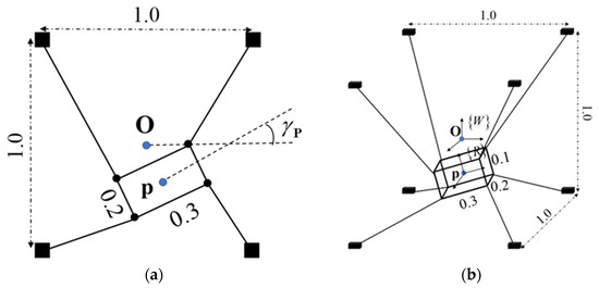
Figure 1.
Two configurations CDPM: (a) 1-redundantly actuated planar CDPM; (b) 2-redundantly actuated spatial CDPM.
2. Cable-Driven Parallel Manipulators Kinematics
Let’s consider the general structure of CDPM illustrated in Figure 2 that contains a moving platform connected with a fixed platform through several flexible cables. The reference frame {W} is attached to the fixed platform and the moving frame {R} is attached to the center of mass of moving platform. For convenience in notation, the right-superscript denotes the frame where the mentioned object reference to, and any vector without a right-superscript is implied to reference to {W}. The general coordinate of {R} with respect to {W} is defined by the vector x = [P θ]T where P = [xp yp zp]T and θ = [αp βp γp]T are the positioning vector of center of mass and rotational vector that represents Euler angle (z-y-x) of the moving platform, respectively. Let Ai and Bi be the positioning vectors that represent the end of the ith cable at the pole and at the moving platform, respectively. According to Figure 2, we have ai = AiBi and bi = PBi. If the general coordinate of the moving platform is given, then the direction of tension exerted on any cable can be obtained through Equation (1).
where is the rotational matrix that represents the orientational of {R} respect to {W} and it can be defined by (2).
where Cx and Sx represent for cos(x) and sin(x), respectively.
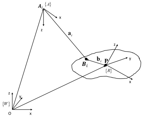
Figure 2.
General kinematic model of CDPM.
In order to balance the external wrench ψe that exerted on P, the actuators mounted in the fixed frame are controlled to create cable tension forces. Moreover, the cable tension forces also affect cable lengths, while cable lengths are desired results in the kinematic problem of CDPM. Hence, the derivation of the relationship between ψe and cable tension forces is an interesting issue. Let m and n be the degree of freedom of moving platform and the number of cables used in system, respectively. Considering the static equilibrium system of the moving platform, the relationship between the cable tension force and external wrench is established in Equation (3).
where W ∈ Rmxn is the wrench matrix that has ith column vector is defined in (4), and t = [t1 … t2] is the vector that represents the set of magnitude of cable tension forces with ti ≥ 0, ∀i = {0, …, n}.
3. The Properties of Wrench-Closure Workspace
In the following section, for any vector v ∈ Rn and scalar a, we denote that v = a means that vi = a, ∀i = {0…, n} and the other binary conditional operators are analogous to that.
According to Equation (3), let ω = {w1,…, wn} be the set of column vectors of given wrench matrix; the external wrench ψe can be considered as a non-negative combination of ω since t ≥ 0. Let Sψ be the set of all nonnegative combinations of ω and can be expressed as (5).
where pos(ω) denotes the nonnegative linear span of ω.
Again, on the problem of kinematics, the wrench matrix W depends on the pose x of the moving platform. Hence, Sψ also depends on x. On the other hand, in this paper, we are interested in the set of poses, in which there always exists at least one set of non-negative tension forces balance arbitrary, given external wrench ψe. The set of these poses is also known as the wrench-closure workspace, and this can be expressed as (6).
We can express (6) as the condition for pose x to be in WCW by (7).
In convexity analysis, if ω non-negatively spans ℝm, then the spanning set ω must hold at least m + 1 vectors, and if ω just has m + 1 vectors, then they should be affinely independent.
According to the results from Theorem 3.6 of Davis [19] and Theorem 2.3 of Conn, Scheinberg and Vicente [20], we can extract the condition (7) into two simpler conditions, which is stated in Theorem 1.
Theorem 1.
A general coordinate x of moving platform belongs to the wrench-closure workspace of a certain CDPM that must satisfy these following conditions:
The Equation (8) is the necessary condition and it is equivalent to the wrench matrix W has full-rank. If dim(W) < m then the system (3) has no solution, even if t is arbitrarily chosen in Rn. On the contrary, if the condition (8) is satisfied, then ω(x) non-negatively linear span the set which always contains a simplex cone. The condition (9) is sufficient for the set ω(x) to nonnegatively linear span Rm. The Equation (9) is equivalent to Equation (10), in which the geometrical interpretation is easily archived.
where m-first column vectors in W are linearly independent.
For convenience, let ωA = {w1,…, wm} be the set of m-first column vectors in W and ωB = {wm+1, …, wn} be the set of remaining vectors. Geometrically, the condition (10) can be interpreted that the intersection between interior of cones spanned by ωB and -ωA must exist.
For instance, let us consider a 3 × 5 wrench matrix W = [w1 w2 … w5] whose column vectors are divided into two sets, ωA = {w1, w2, w3} and ωB = {w4, w5}. These sets and their positive spanning sets are illustrated in Figure 3. Since ωA is a linearly independent set (w1, w2 and w3 do not lie in a common plane), the Equation (8) is satisfied. Secondly, the intersection between pos(−ωA) and pos(ωB) is not empty, hence, the Equation (9) is also satisfied. Therefore, the given wrench matrix that has column vectors illustrated in Figure 3 has a general coordinate presented in the wrench-closure workspace.
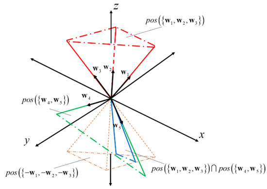
Figure 3.
Specific case of a certain 2-redundant actuators-planar CDPM when general coordinate of moving platform presented in the wrench-closure workspace.
The special case of this problem is CDPM contains only one redundant actuator, i.e., n − m = 1. In that case, the condition (10) is simplified to (11).
where λ = [λ1 λ2 … λm]T and λi = ti/tn.
Indeed, vector wn non-negatively spans a ray and this must belong to a cone spanned by −ωA to satisfy the Equation (10).
For instance, let us consider a 3 × 4 wrench matrix W = [w1 w2 w3 w4] which has column vectors illustrated in Figure 4. Similar to the last example, since w1, w2 and w3 are linearly independent, we have that span({w1, w2, w3, w4}) = R3. Moreover, w4 belongs to the negative spanning set of w1, w2 and w3 then pos({w1, w2, w3, w4}) = R3.
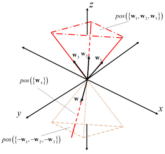
Figure 4.
Specific case of a certain 1-redundant actuator-planar CDPM when general coordinates of moving platform are presented in the wrench-closure workspace.
4. Simplify Problem by Using Linear Equivalence
Let M ∈ Rmxm be the square matrix established by taking m-column vectors in W and H ∈ Rmx(n−m) consist of the remaining column vectors in W. According to Theorem 1, if x ∈ WCW ⊂ Rm then ω must contain m linearly independent vectors, i.e., there exist a certain set of m-column vectors in W that form the nonsingular matrix M.
Theorem 2.
Given that N ∈ Rmxm is the non-singular matrix, if ω non-negatively spans Rm then N.ω = {Nw1, Nw2, …, Nwn} also non-negatively spans Rm. If ω does not nonnegatively span Rm, then N.ω also does not non-negatively span Rm.
Proof of Theorem 2.
The proof of the first part of Theorem 2 can be derived from the proof of Theorem 4.6 by Regis in [21]. The minimum condition in order for ω nonnegatively span Rm is that ω must contain at least m + 1 affinely independent vectors. Hence, let consider {w1, w2, …, wm+1} be the set of m + 1 affinely independent vectors in ω. Suppose {Nw1, Nw2, …, Nwm+1} is affinely dependent then ∃i ∈ {1, …, m+1} such that Nwi = Σj = {1, …, i−1, i+1, …,m} Nwj. Since N is invertible, we have N−1Nwi = N−1Σj = {1, …, i−1, i+1, …, m} Nwj. Then, by simplifying both sides, we have wi = Σj = {1, …, i−1, i+1, …, m}wj. However, it violates the assumption in Theorem 2. Following the procedure analogous to that employed for the proof of the second part. □
According to Theorem 2, we can state that if ω does or does not non-negatively span Rm than M−1ω also does or does not nonnegatively span Rm. Thus, Equation (3) can be replaced by any of the Equations (12)–(14), but the condition represented by (9) is not influent.
where tA = [t1 t2 … tm]T and tB = [tm+1 tm+2 … tn]T.
Based on Equation (12), we can write M−1ω = {e1, e2, …, em, M−1wm+1, …, M−1wn}, where {e1, e2, …, em} is the standard basis of Rm. Following the Equation (10), the set of m-first column vectors in W is now represented as ωA = {e1, e2, …, em} and the set of remaining vectors is ωB = {M−1wm+1, …, M−1wn}. Geometrically, ωA non-negatively spans closed nonnegative hyperoctant of Rm, Rm+. Hence, if x belongs to WCW, then the intersection between the interior of cone ωB and open negative hyperoctant Rm− should not be empty. For instance, Figure 5 illustrated the specific case of 2 redundant actuators-planar CDPM when a general coordinate is presented in wrench-closure workspace and linear equivalence was applied to the wrench matrix generated by the considered general coordinate.
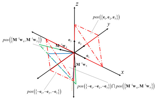
Figure 5.
Specific case of a certain 2-redundant actuators-planar CDPM when general coordinate of moving platform presented in the wrench-closure workspace and linear equivalence is applied.
In the special case, when n − m = 1, the sufficient condition for the general coordinate belonging to WCW is simplified as (15).
In the general case, when n − m > 1, we cannot determine whether x does or does not belong to WCW only based on the signs of elements in ωB. However, the linear equivalence nonnegative span set of ω simplifies the condition (10). Since ωA already non-negatively spans Rm+, in Equation (14), it is equivalent to ItA > 0, ∀ tA > 0, the sufficient condition for the general coordinate x belongs to WCW is defined by (16).
For a more compact system of inequalities, we can rewrite (16) as (17).
Theorem 3.
A general coordinate x belongs to the wrench-closure workspace of a certain CDPM if (8) and (17) are satisfied.
In the next section, we will introduce the procedure in order to determine whether (17) does or does not have solution.
5. Checking the Feasibility of a System of Inequalities
Based on the matrix theory for solving the system of linear equations, L. Dines developed his own theory on determining the general solution of system of linear inequations. He also proposed the method used to check the feasibility of them. In this section, we will introduce L. Dines’ theory, make our conclusions and establish our algorithm to solve the system (17).
Let’s consider the system of inequations in form of Ax > 0 where A is a coefficient matrix. L. Dines proposed the concepts I-positive, I-negative and I-definite to establish his own work on checking the feasibility of Ax > 0. These concepts can be summarized by the Definition 1.
Definition 1.
If matrix A (18) contains a column in which all elements are positive (or negative) then A is said to be I-positive (or I-negative) with respect to that column. In both cases, generally, matrix A is said to be I-definite with respect to that column. Additionally, if matrix A is I-definite (I-positive or I-negative), then it must contain at least one column in which all elements have same sign (positive or negative).
Conclusion 1.
According to definition 1, we can conclude that if matrix A is I-definite then Ax > 0 is feasible.
Proof of Conclusion 1.
Let {a1, a2, …, an} be the set of column vectors of A, if A is I-definite then there exist an column vector ai, i ∈ {1, 2, …, n}, in which all elements has same sign. Hence, we always have a set of solution x = [x1 x2 … xi … xn]T = [0 0 … a … 0]T, where a > 0, in a feasible region. □
However, conclusion 1 is not sufficient to check the feasibility of system Ax > 0, i.e., If the matrix A is not I-definite, then we cannot conclude that Ax > 0 is feasible or not. In this case, L. Dines introduced the concepts of I-complement and I-minors. The I-complement of the rth column of matrix A, A1r, is the matrix that can be established as follows.
Separate the elements of rth column of A, [a1r a2r … amr]T, into three sets based on their sign: positive set P = {ai1r, ai2r, …, aiPr}, negative set N = {aj1r, aj2r, …, ajNr} and zero set Z = {ak1r, ak2r, …, akZr}.
Then, we orderly top-down establish each row of A1r by orderly combining air and ajr, and used them to compute each element of the corresponding row by the second-order determinant (19), where value of k corresponding to the order of elements in the considered row.
The last rows of A1r are derived from the rows of A that contain akr and formed by taking these rows without elements akr.
By that procedure, the matrix A1r which has P = N + Z rows and n − 1 columns is established. As we can see, if the matrix A has n columns, then there were n I-complements {A11, A12, …, A1n}, and the set of these matrices is called I-minors of n − 1 columns of the matrix A. By employing the above procedure to each I-minor of n − 1 columns of the matrix A, I-minors of n − 2 columns of the matrix A can be archived. Recursively, we can obtain I-minors of n − h columns of the matrix A where h < n.
Based on Theorem 1 stated by Dines in [18], we can derive the sufficient condition in order to check the feasibility of system of inequalities in form of Ax > 0.
Theorem 4.
The system of inequalities in form of Ax > 0 is feasible if there exists at least one I-minor of n-h column which is I-definite where h < n.
Since the system (17) in form Ax > 0, so we can apply Theorem 4 to it and make our conclusion.
Conclusion 2.
The system of inequalities (17) is feasible if there exists at least one I-minor of h columns which is I-positive.
After the whole process of checking the feasibility of given system (17), we have a sufficient condition to determine whether the pose x which generates the wrench matrix W belongs to WCW or does not. The overview of the whole process to check the feasibility of certain pose is illustrated in Figure 6.
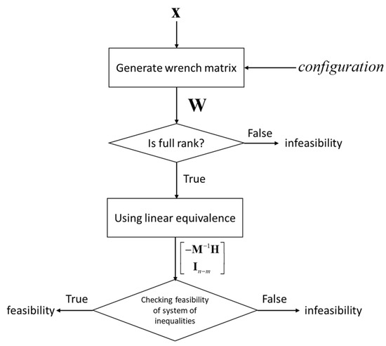
Figure 6.
The overview of proposed algorithm to check the feasibility of certain pose.
6. Case Studies and Simulation
In this section, the proposed wrench closure condition is applied to search for the wrench-closure workspace of two configurations CDPM defined in Figure 1. For convenience, we define three types of WCW:
- Total orientation wrench closure workspace (TOWCW): Other than the definition in [22], in this article, TOWCW presents the whole WCW when position and orientation of moving platform are considered as variables. Notice that, because of the limitation in visualization, we can plot the TOWCW of 3-dof CDPM.
- Constant orientation wrench closure workspace (COWCW): For 6-dof CDPM, we can visualize the projection of its TOWCW on up to 3-dimensional workspace. If the projected space was only related to the position of moving platform, this projection is called COWCW. For 3-dof CDPM, COWCW is the section obtained at specific γp.
- Constant position wrench closure workspace (CPWCW): Similar to COWCW, CPWCW is the projection of TOWCW when the projected space was only related to the orientation of moving platform, i.e., position of moving platform is constant.
As shown in Figure 7, WCW of the first configuration CDPM shown in Figure 1 is generated by point-wisely employing proposed WWC in the grid map, which has a dimension of 1 m × 1 m × 2π and resolution of 0.02 m × 0.02 m × 0.02 rad. Total orientation WCW of planar CDPM is a subset of 3-dimensional space (xP-yP-γP); it is illustrated in Figure 7a. Moreover, 2-dimensional sections of total orientation WCW of planar CDPM obtained at γP = 0°, 0.052 rad and −0.052 rad are also plotted in Figure 7b–d. The orange, yellow and purple closed curves in Figure 7a represent the boundaries of slices that present in Figure 7b–d, respectively. However, this configuration is simple, since it has 3-dof and only one redundant actuator. Hence, it cannot verify the feature “applicable for a completely or redundantly restrained CDPM” of proposed WWC. The second configuration CDPM shown in Figure 1 is a 2-redundantly actuated spatial CDPM, and it can be used to reinforce the flexibility of proposed WWC.
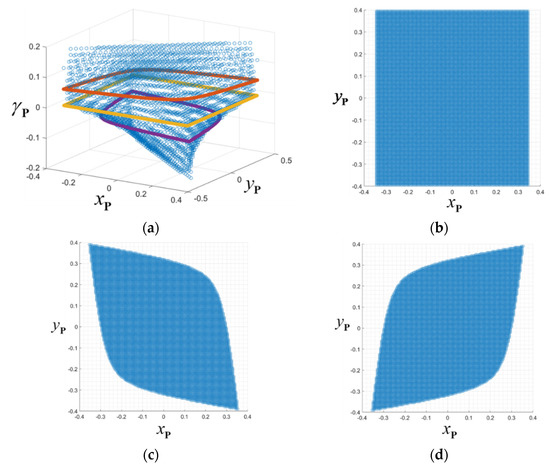
Figure 7.
Wrench closure workspace of the first configuration shown in Figure 1. (a) Total orientation WCW; (b) 0 rad-section; (c) 0.052 rad-section; (d) −0.052 rad-section.
As shown in Figure 8, WCW of the second configuration CDPM shown in Figure 1 is generated by applying proposed WWC. Constant orientation WCW with αP = 0, βP = 0 and γP = 0.052 rad, and constant position WCW with xP = 0, yP = 0 and zP = 0 are shown in Figure 8a,b, respectively. As shown in Figure 7c and Figure 8a, the cross-section perpendicular to the z-axis of COWCW of the spatial CDPM is trickly equivalent to the COWCW of the planar CDPM due to their similar dimensions. This comment is also verified by Pham et al. in [16]. In Figure 8b, the CPWCW is not continuous and in practice, this type of CDPM just can work on a small set of orientational spaces.
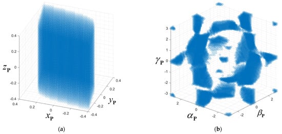
Figure 8.
Wrench closure workspace of the second configuration shown in Figure 1. (a) constant orientation WCW with αP = 0, βP = 0 and γP = 0.052 rad; (b) constant position WCW with xP = 0, yP = 0 and zP = 0.
In simulations, the time-consumption of proposed WCC used to determine whether a pose presents in WCW is also considered. Time-consumption is not the same in each performance due to two factors: size of wrench matrix and the interruption of algorithm. The first factor depends on configuration of CDPM, it is related to the number of used cables and DoF of moving platform. In the worst case, when a pose belongs to WCW and the algorithm for checking the feasibility of system of inequations must evaluate all I-minor of given wrench matrix. The second factor is the interruption of the algorithm. Our algorithm will orderly evaluate I-minor of the given wrench matrix until one of them is I-definite. In the best case, the wrench matrix is not full-rank, the pose absolutely does not belong to WCW and the algorithm does not take place.
7. Conclusions
In this paper, the wrench closure condition that can be applied for a completely or redundantly restrained CDPM is our main contribution. Based on the properties of WCW, theorem 1 is given to determine the feasibility of a pose in WCW. By classifying the type of CDPM, n = m + 1 and n > m + 1, and using linear equivalence theory, the sufficient condition of WCC is simplified. Finally, applying the algorithm to check the feasibility of system of inequalities, given that the pose of the moving platform determined belongs to WCW or does not.
Our proposed WCC proved to be synthetic and to be an algorithm to rapidly determine whether a pose belongs to the WCW or not. The overview of our proposed algorithm is illustrated in Figure 6. This algorithm can be combined with any search algorithm to generate the WCW. Two different cases study were also given, the first one is one redundant actuator planar CDPM and the other is two redundant actuators spatial CDPM. By employing the proposed algorithm with point-wise search method, the WCW or spatial WCW of these CDPM are determined and evaluated.
Author Contributions
Conceptualization, N.T.T.; methodology, N.T.T.; software, P.G.L.; validation, P.G.L.; formal analysis, P.G.L.; resources, N.T.T.; data curation, P.G.L.; writing—original draft preparation, P.G.L.; writing—review and editing, P.G.L.; visualization, P.G.L.; supervision, N.T.T.; project administration, N.T.T.; funding acquisition, N.T.T. All authors have read and agreed to the published version of the manuscript.
Funding
This research received funding from Ministry of Education and Training of Vietnam.
Institutional Review Board Statement
Not applicable.
Informed Consent Statement
Not applicable.
Data Availability Statement
Not applicable.
Acknowledgments
This work belongs to the project grant No: B2021-SPK-05. funded by Ministry of Education and Training, and hosted by Ho Chi Minh City University of Technology and Education, Vietnam.
Conflicts of Interest
The authors declare no conflict of interest.
References
- Bosscher, P.; Williams, R.L., II; Bryson, L.S.; Castro-Lacouture, D. Cable-suspended robotic contour crafting system. Autom. Constr. 2007, 17, 45–55. [Google Scholar] [CrossRef]
- Williams, R.L.; Xin, M.; Bosscher, P. Contour-Crafting-Cartesian-Cable Robot System Concepts: Workspace and Stiffness Comparisons. In Proceedings of the 32nd Mechanisms and Robotics Conference, New Yok, NY, USA, 3–6 August 2008; ASME International: New York, NY, USA, 2008; Volume 43260, pp. 31–38. [Google Scholar]
- Usher, K.; Winstanley, G.; Carnie, R. Air Vehicle Simulator: An Application for a Cable Array Robot. In Proceedings of the 2005 IEEE International Conference on Robotics and Automation; Institute of Electrical and Electronics Engineers (IEEE), Barcelona, Spain, 18–22 April 2005; pp. 2241–2246. [Google Scholar]
- Salafian, I. Development of the End-Effector of a Cable-Driven Parallel Manipulator for Automated Crop Sensing. Master’s Thesis, University of Nebraska—Lincoln, Lincoln, NE, USA, 2017. [Google Scholar]
- Do, H.-D.; Seo, J.-H.; Park, J.-O.; Park, K.-S. Wrench-feasible workspace analysis considering aerodynamics of aerial robotic camera under high speed. Microsyst. Technol. 2017, 23, 5257–5269. [Google Scholar] [CrossRef]
- Luan, P.G.; Thinh, N.T. Empirical Quasi-Static and Inverse Kinematics of Cable-Driven Parallel Manipulators In-cluding Presence of Sagging. Appl. Sci. 2020, 10, 5318. [Google Scholar] [CrossRef]
- Berti, A.; Gouttefarde, M.; Carricato, M. Dynamic Recovery of Cable-Suspended Parallel Robots After a Cable Failure. In Advances in Robot Kinematics; Lenarčič, J., Merlet, J.P., Eds.; Springer Proceedings in Advanced Robotics Series; Springer: Cham, Switzerland, 2018; Volume 4. [Google Scholar]
- Passarini, C.; Zanotto, D.; Boschetti, G. Dynamic Trajectory Planning for Failure Recovery in Ca-ble-Suspended Camera Systems. ASME J. Mech. Robot. 2019, 11, 021001. [Google Scholar] [CrossRef]
- Duan, Q.J.; Duan, X. Workspace Classification and Quantification Calculations of Cable-Driven Parallel Robots. Adv. Mech. Eng. 2014, 6, 358727. [Google Scholar] [CrossRef]
- Gouttefarde, M.; Gosselin, C.M. Analysis of the wrench-closure workspace of planar parallel cable-driven mechanisms. IEEE Trans. Robot. 2006, 22, 434–445. [Google Scholar] [CrossRef]
- Gouttefarde, M.; Gosselin, C.M. Wrench-closure workspace of six-dof parallel mechanisms driven by 7 cables. Trans. Can. Soc. Mech. Eng. 2005, 29, 541–552. [Google Scholar] [CrossRef]
- Gouttefarde, M.; Merlet, J.P.; Daney, D. Determination of the wrench-closure workspace of 6-DOF parallel ca-ble-driven mechanisms. In Advances in Robot Kinematics; Springer: Berlin/Heidelberg, Germany, 2006; pp. 315–322. [Google Scholar]
- Lau, D.; Oetomo, D.; Halgamuge, S.K. Wrench-Closure Workspace Generation for Cable Driven Parallel Manipulators Using a Hybrid Analytical-Numerical Approach. J. Mech. Des. 2011, 133, 071004. [Google Scholar] [CrossRef]
- Li, T.; Tang, X.; Tang, L. Algebraic expression and characteristics of static wrench-closure workspace boundary for planar cable-driven parallel robots. Adv. Mech. Eng. 2016, 8, 1687814016638217. [Google Scholar] [CrossRef]
- Pott, A.; Kraus, W. Determination of the wrench-closure translational workspace in closed-form for cable-driven parallel robots. In Proceedings of the 2016 IEEE International Conference on Robotics and Automation (ICRA); Institute of Electrical and Electronics Engineers (IEEE), Stockholm, Sweden, 16–21 May 2016; pp. 882–887. [Google Scholar]
- Pham, C.B.; Yeo, S.H.; Yang, G.; Kurbanhusen, M.S.; Chen, I.-M. Force-closure workspace analysis of cable-driven parallel mechanisms. Mech. Mach. Theory 2006, 41, 53–69. [Google Scholar] [CrossRef]
- Diao, X.; Ma, O. A method of verifying force-closure condition for general cable manipulators with seven cables. Mech. Mach. Theory 2007, 42, 1563–1576. [Google Scholar] [CrossRef]
- Dines, L.L. Systems of Linear Inequalities. Ann. Math. 1919, 20, 191. [Google Scholar] [CrossRef]
- Davis, C. Theory of Positive Linear Dependence. Am. J. Math. 1954, 76, 733. [Google Scholar] [CrossRef]
- Conn, A.R.; Scheinberg, K.; Vicente, L.N. Introduction to Derivative-Free Optimization; Society for Industrial & Applied Mathematics (SIAM): University City, PA, USA, 2009. [Google Scholar]
- Regis, R.G. On the properties of positive spanning sets and positive bases. Optim. Eng. 2015, 17, 229–262. [Google Scholar] [CrossRef]
- Gouttefarde, M.; Daney, D.; Merlet, J.-P. Interval-Analysis-Based Determination of the Wrench-Feasible Workspace of Parallel Cable-Driven Robots. IEEE Trans. Robot. 2010, 27, 1–13. [Google Scholar] [CrossRef]
Publisher’s Note: MDPI stays neutral with regard to jurisdictional claims in published maps and institutional affiliations. |
© 2021 by the authors. Licensee MDPI, Basel, Switzerland. This article is an open access article distributed under the terms and conditions of the Creative Commons Attribution (CC BY) license (https://creativecommons.org/licenses/by/4.0/).