1. Introduction
Reconfigurable manufacturing systems are necessary for the development of flexible production systems [
1,
2]. For this reconfigurability to be possible, industrial robots must receive real-time sensor feedback, an important part of which is visual feedback. This is necessary for a variety of applications, such as navigation, part identification and handling, human collaboration, etc. Visual feedback also may be fused with data from other sensors for a more complete digital representation of the surrounding environment. Generally, high accuracy is needed for the vision applications, but that accuracy varies according to each application. For example, a mechanical gripper will require much more accuracy to manipulate an object without damaging it, compared to a suction gripper. According to the desired accuracy and data types, 2D or 3D, different camera types are chosen, pinhole or stereo. Depending on the application, 2D or 3D data are extracted. The vision system can be either object-related or scene-related. Object-related vision systems regard the detection of objects, which allows the handling of them, such as picking or placing objects in workstations. For object-related vision systems, the camera is usually mounted near the acting tool of the robot arm. Scene-related vision systems regard the awareness of the robot for the environment around it. Examples of scene-related systems are vision systems for localization or collision avoidance, and the camera for these systems is usually mounted on the mobile robot.
The above categories can be classified into two types of robotic perception. Object-related vision belongs to process perception, which represents the cognitive ability of the robot to identify the process parameters and successfully execute a manufacturing task. Scene-related vision belongs to environment perception, which is the cognitive ability of the robot to understand its environment in order to detect obstacles, areas of interest, its own place within a robotic cell, etc.
There are many examples in industry where process and shopfloor perception have been implemented. In [
3], a method using contour detection was proposed in order to avoid collisions when navigating a mobile robot, by recognizing the boundaries between objects and free space. Methods such as CAD matching have been used in many cases for object detection and manipulation [
4]. In [
5], a single camera was used to detect landmarks that are used for accurate localization of a mobile platform, which is necessary for the successful execution of tasks in complex manufacturing environments.
There are challenges in using a vision system in processes in a robust manner. Even when initial calibration of the camera system is performed, which estimates the parameters of a lens and image sensor of a video camera, temperature changes or light changes can greatly affect the vision precision. There are also cases in which too much data is unnecessary and burdens the system, and simple solutions must be found instead. This is due to systems with limited resources such as memory and bandwidth, where too much data causes severe challenges [
6].
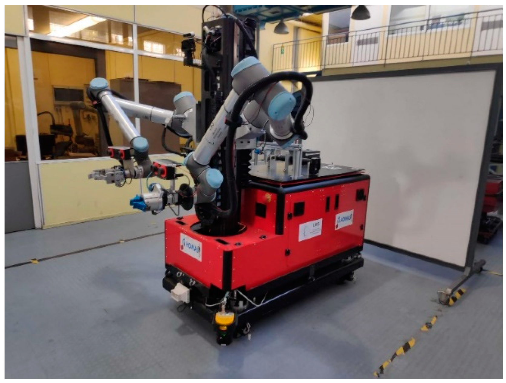
The technologies of this work were implemented on a robotic system based on a hybrid dynamic reconfigurable shopfloor that was suggested by Kousi et al. [
7] enabled through mobile dual-arm workers, the so-called mobile robot platforms (MRPs) visualized in
Figure 1. It based its reconfigurability on its ability to adapt to changes on the shopfloor, which are detected online by the sensors.
There has been a lot of research and work done on vision systems in robotics [
8], while various other novel technologies for controlling mobile robots have been implemented, including new technologies such as augmented reality and brain–computer interfaces [
9,
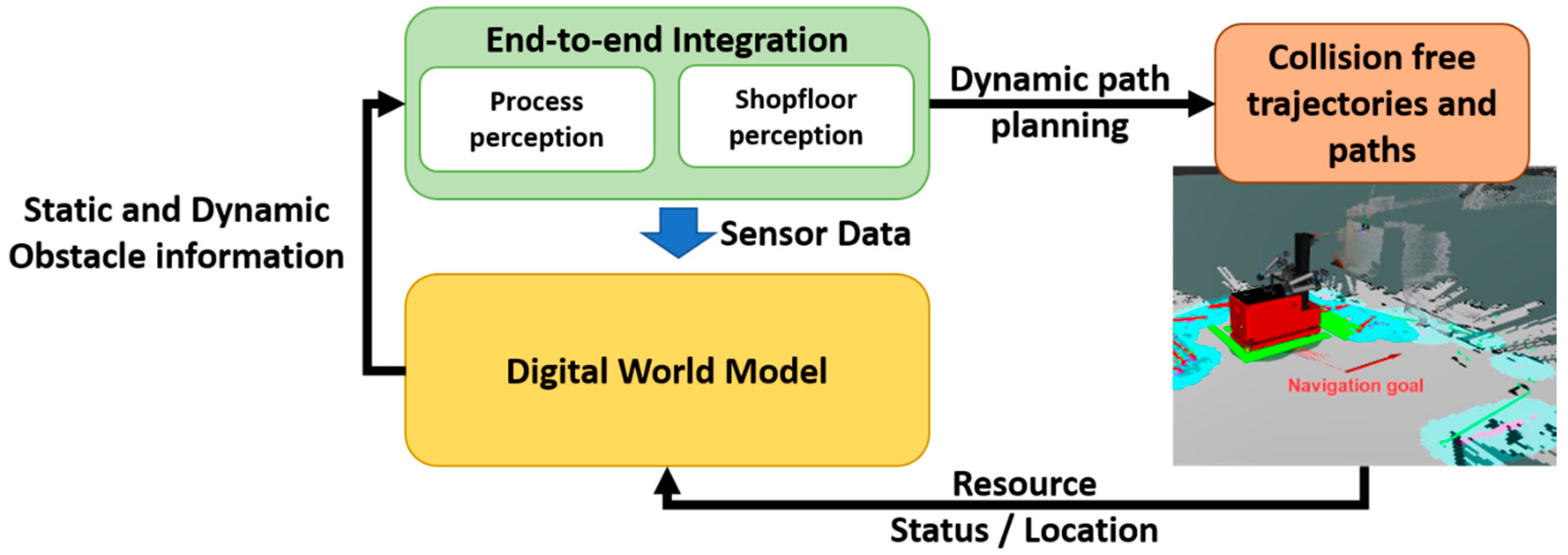
10]. The present work focuses on developments of vision systems for mobile robot workers that can enhance flexibility and autonomy through cognition, by working on four pillars: (a) achieving accurate positioning of a mobile robot in a factory environment by using vision-based localization methods; (b) achieving detection of objects of varying geometrical characteristics with the required accuracy for the desired process (assembly, screw-fastening, drilling, etc.); (c) integrating the above applications end-to-end to generate motion paths toward the detected points of interest; and (d) combining the above with the use of static and dynamic obstacle information from a digital twin for real-time planning of collision-free trajectories and paths.
For the validation of these methods, the proposed framework was implemented in an assembly line of the front suspension of a vehicle from the automotive industry. The image-processing methods that will be presented and integrated are based on contour detection, 3D cloud matching, CAD matching and marker tracking.
The structure of this paper is as follows.
Section 2 presents the existing research on the topics discussed in this manuscript,
Section 3 presents the approach for the shopfloor and process perception modules, and
Section 4 focuses on the implementation.
Section 5 presents the automotive case study that was used to validate the methods in this manuscript,
Section 6 presents the results, and
Section 7 finishes with the discussion of the results, the conclusions and future work.
2. Literature Review
2.1. Mobile Robots
The implementation of mobile robotics in industry offers a set of specific advantages that the traditional industrial robots, such as robots that are static or move on rails, lack—namely, task flexibility and robotic mobility [
11]. The introduction of these robots in assembly lines also enables reduced duration of breakdowns, lower commissioning time, minimum need for human intervention due to their autonomous behavior and higher production variability [
12]. Developments of mobile robots have led to various relevant research topics, such as methodologies that can make use of observations of mobile robots on shop floors and build up the fidelity of simulations based on those shop floors [
13].
For autonomous industrial mobile manipulators (AIMM), as they are called, it is easier to adapt to changes in the environment and are able to perform a wider variety of tasks. The usual architecture of these robots is a manipulator mounted on a mobile platform.
An example of such a robot is the “Little Helper” [
11], an experimental robot that utilizes a generic product platform architecture and universal communication language, by use of commercial off-the-shelf hardware components and software systems, focusing on flexibility and versatility in order to become a plug-and-produce solution. In [
14], the Little Helper was used in experiments that helped validate the concept of general, self-asserting robot skills for manufacturing.
Another similar robot is SwRI’s “Mr. Roam” [
15], which consists of a Vetex mobile platform integrated with a Motorman robot arm (SIA-20) and a Nikon metrology iGPS device to create an off-the-shelf manipulator. SwRI validated the industrial application of the robot in an experiment on an aircraft wing model.
KUKA’s “KMR iiwa” [
16] combines a mobile, flexible platform with the sensitive LBR iiwa lightweight robot arm. The robot’s advantages include flexibility, autonomy, omnidirectional agile movement, precision of up to +/− 5 mm, intelligence in moving around obstacles and finding new paths, and easy operation.
The “KMR QUANTEC” [
17] is a combination of KUKA robots, mobile platforms and other industry-standard components. The variability in the components allows customized solutions according to each user’s individual requirements. It consists of the KUKA omniMove platform and a KUKA robot of the KR QUANTEC series, as well as software and a controller. It is safe, mobile, independent, multifunctional, adaptable and variable.
2.2. Shopfloor Perception
Nowadays, vision sensors are used extensively in shopfloor perception for navigation or localization of the mobile robot. They can be used either on their own or in combination with other sensors, such as laser scanners, to achieve more accurate results.
Despite recent advances in the area of navigation, there are still open questions and uncertainty, especially regarding navigation in unknown environments, which has been researched in the last decades with several approaches, such as fuzzy-set-based representation [
18]. Topological localization and world modeling are considered effective solutions for uncertainty in position, but the improvement of perception capabilities to recognize objects in the environment also has been suggested [
19].
The many types of sensors used for mapping, localization and navigation [
20] that measure external information from the environment include GPS, SONAR, lase and infrared sensors. Odometry is calculated from encoders installed on the wheel, but they accumulate errors over time and need to be supplemented with other sensor data. GPS is a good choice for outdoor use, but does not work as well indoors, close to buildings or on narrow streets.
SONAR can be utilized as a low-cost system that is effective in spaces with low visibility or with other difficulties such as being surrounded by mirrors [
21], but its precision is low. Laser scanners are often used in combination with odometry for navigation of mobile robots.
Vision sensors present an alternative for the above sensors, or a complementary measure to ensure accuracy in real-time applications. Laser, ultrasonic or infrared sensors give data in an imperceptible way, from light radiation or sound signals transmitted from a source mounted on the robot, for example [
22]. The system could produce inaccuracies due to the interruption of the traveling signal caused by disturbances in the surrounding environment. Vision sensors are also not very power-consuming and usually cost less than their lase counterparts, providing a lot of information, including 2D and 3D data, depending on the sensor. They can also be used both indoors and outdoors, although they suffer from light variation, and great care should be taken in the choosing of the appropriate camera.
In [
23], a method was proposed for real-time indoor robot localization, using a stationary fisheye camera not mounted on the robot, but instead installed on the ceiling of the room, although the localization was not very accurate, especially when the robot was further away from the camera.
In [
24], a single camera mounted on a mobile robot was used for path generation of the robot. Floor segmentation was used to identify the free space on the floor, while a laser source was used complementary, in order to detect obstacles and irregularities, such as a hole in the floor. The depth estimation was calculated using the camera, not a laser.
SCARF, a color vision system, was developed in [
25] to track roads and intersections and for navigation in a variety of weather conditions. It used Bayesian classification to determine road-surface likelihood for each pixel in a color image.
2.3. Process Perception
Process perception is necessary for any robot that interacts with objects within a process. Object manipulation with predetermined movements is a difficult and dangerous task for mobile robots, demanding the errors of the navigation and localization processes to be negligible. Object detection is a fundamental problem in computer vision and has been prominent for two decades, and its solutions have evolved greatly [
26]. It is very useful in industrial processes such as welding operations, as presented in [
27] in which a stereo camera was used for path correction; and assembly operations, as presented in [
28] in which a vision system was used for the picking and placing of randomly assorted objects. There are several methods used for object detection in robotic vision, such as segmentation, CAD matching, 3D point-cloud matching and marker detection.
Regarding feature-based methods, they can be classified as local and global. For local features, the approach is the identification of key points in data sets extracted from point clouds, 3D images, etc., and the extraction of a descriptor for the key points, which are matched with descriptors from a database of registered objects.
The SURF [
29] method defines interest points of a given image as salient features from a scale-invariant representation. Then, orientation and invariant descriptors are built by using local gradient statistics. SURF focuses on fast computation of operators using box filters, which enables real-time applications such as tracking and object recognition.
The SIFT [
30] algorithm is also a feature detection algorithm that extracts key points of objects from a set of reference images and detects objects in an image by comparing each feature from the new image to this database, finding candidate-matching features based on the Euclidean distance of their feature vectors.
The B-SHOT descriptor [
31] is a binary descriptor, based on a binary quantization method that converts real valued vectors to binary vectors, which are applied in the SHOT descriptor [
32]. It is used for efficient key point matching on 3D point clouds.
There are many other local-feature methods, such as PHF [
33], NARF [
34] and Harris 3D [
35].
In global-feature methods, a single feature is extracted per object. The input scene is segmented into clusters, and each cluster represents an object candidate. Then a global descriptor is extracted for each cluster and matched with descriptors from an object database, with the correspondences yielding an object classification and pose estimation.
The VHF global feature descriptor [
36] encodes geometry and viewpoint, and can be used as a distinctive signature for the simultaneous recognition of an object and its pose. It has the advantage of being robust to large surface noise and missing depth information. OUR-CVFH [
37] is a method for the estimation of a unique and repeatable reference frame in the context of 3D object recognition from a single viewpoint based on global descriptors. ESF [
38] is a descriptor for partial point clouds based on shape functions capable of training on synthetic data and classifying objects from a depth sensor in a single partial view in a fast and robust manner.
Template-matching approaches work by sliding a template window over an input scene. For each position of the template window on the scene, the similarity between the template and the part of the image covered by the window is noted. Then, matching occurs based on a certain threshold. The speed of the algorithm is challenging since each template is compared to each position on the scene. DOT [
39] is a main method of template matching, measuring the similarity between an input image and a reference image by comparing the orientations of their gradients. The gradients are chosen because they prove to be more discriminant than other forms of representations and are robust to illumination change and noise. LINEMOD is also a template-matching algorithm [
40] that combines two modalities as a similarity measure: color gradient information and surface normal.
2.4. Digital Twin
The digital twin (DT) has gained attention in the last few years, due to the advantages that it may offer in terms of providing perception and cognition abilities in more autonomous and intelligent robotic systems [
41]. Digital twins must have a bidirectional link with the physical with their real systems, thus guaranteeing well-defined services to support various activities such as monitoring, maintenance, management, optimization and safety [
42].
In [
43], a digital twin was designed to support the design, build and control of human–machine cooperation, by creating a digital counterpart of a human–robot collaborative workplace. A novel DT prototype was developed in [
44] to analyze the requirements of communication in mission-critical applications such as mobile-network-supported remote surgery, demonstrating the use of DTs in a variety of domains.
The combination of virtual reality and DTs has also been introduced [
45], which enabled the operator to view the DT from the inside. The simulation system developed, which consisted of the full synchronization between real and virtual industrial robots, implemented a universal software base, which could be extended to control and program DTs of different industrial robots by using the Unity3D game engine.
Digital twins are also useful in product design, as suggested in [
46], in which a concept of DT technology based on a review of DT background and the architecture for a product DT based on the systematic analysis of its connotation was proposed. Kousi et al. [
47] demonstrated the use of the digital twin for the adaptation of robot behavior, enabling flexibility in robotic assembly lines. The focus was on dynamic update of the digital twin based on real-time sensor or resource data coming from the actual shopfloor.
2.5. Progress Beyond the State of the Art
Currently, in manufacturing plants, mobile robots navigate from workstation to workstation using shopfloor perception methods that are based on sensors, which often add an error to the final position. This error is an obstacle to any object manipulation in those workstations. To compensate for that error, they often facilitate a physical connection with the workstations, enabled by physical clamping mechanisms, in what is called physical docking. This requires a specific geometry from the robots and workstations, which adds physical constraints to the execution of the production.
In this paper, a framework is proposed for the proper functionality of a mobile robot in a fenceless manufacturing environment with several workstations. First, the navigation is performed using data from laser sensors, then a much more accurate localization procedure, based on a camera mounted on the robot, is performed to compensate for the error in navigation, in what is called virtual docking of the mobile robot in front of the workstations. Finally, an object detection method is used using cameras mounted on the manipulator of the mobile robot to detect the object to be manipulated with even greater accuracy. The result is a system that minimizes the error, while forgoing the constraints a physical clamping system would add to the production at the same time. These functionalities also allow for easier reconfiguration of the execution in case of error, or in case of rearrangement of the shopfloor, that with a physical clamping system would be much more costly in time and actual cost.
3. Approach
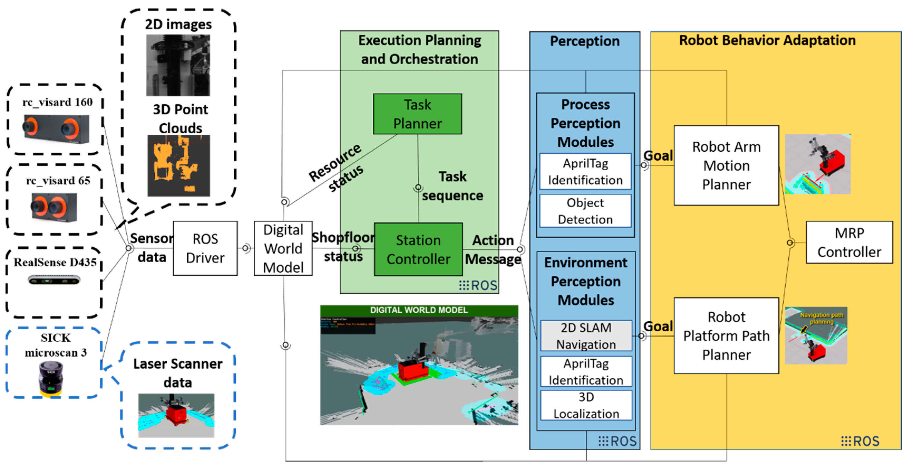
The approach of this work can be classified into two categories of developed technologies. The first comprises a shopfloor perception method, specifically a localization method for docking the MRP in front of the workstations of the shopfloor. The second focuses on process perception, namely object detection for the manipulation of objects. In
Figure 3, the overall approach is presented. On the left, the various sensors that the MRP utilizes for data required for shopfloor and process perception are shown.
The software architecture of the approach is based on the Robot Operating System (ROS), which provides the drivers that handle the data of the sensors used and feed it to a digital world model, also called a digital twin. The Digital twin provides input to a task planner, which plans the task sequence and communicates with a skill-execution engine, also known as a station controller, which executes the modules when a task requires them. The shopfloor perception module is responsible for the navigation of the mobile robot as well as the localization, while the process perception module is responsible for the object detection. The path planner calculates a path for the movement of the robot platform and communicates with the MRP controllers, which actuate the movement. Likewise, the motion planner calculates a path for the manipulators of the MRP and communicates with their controller for their movement according to input from the object detection module of the process perception. The approach for the different modules of perception as well as the digital twin are analyzed below, while the implementation of the station controller is analyzed in
Section 4.
3.1. Digital Twin Module
The digital world model, or digital twin, aims to enable the digital representation of the real-time shopfloor status by enhancing the static layout information with the real-time feedback coming from the resources and the shopfloor/resource on board sensors. Thus, the world model’s functionalities have been classified into two main categories:
Virtual representation of the collaborative environment combining multiple sensor data and the geometrical knowledge of the workplace.
Semantic representation of the shopfloor status through a unified data model, including the geometrical state as well as the workload state.
The components of the digital world model are:
The graphical user interfaces for easy configuration of resources and sensors, which allow the user to view information about the status of the system, as well as to insert information and reconfigure the digital world.
The resource manager, which is responsible for registering in the system any new resource introduced on the shopfloor, and has two primary responsibilities: the proper registration of each resource on the shopfloor and the provision of semantic information related to it based on a unified data model that can serve multiple resource types (humans, and mobile and stationary robots).
The sensor manager, similar to the resource manager, is responsible for the configuration all the sensors inside the shopfloor (stationery and resource onboard sensors). Thus, a respective registration procedure takes place for setting the launch files, and similar to the resources, each sensor needs to have a ROS driver for providing its data into the ROS network and to define its position inside the global TF-tree.
- ○
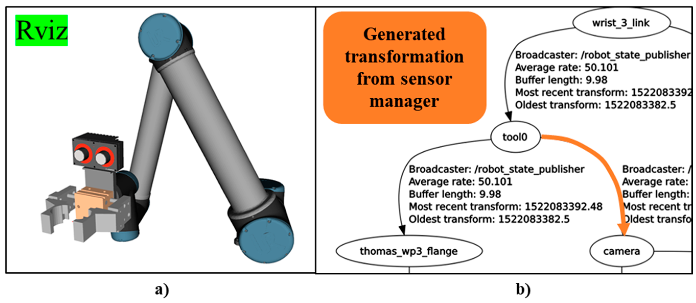
The ROS driver for both cameras has been already developed using ROBOCEPTION. At the registration of these sensors, the manager takes care of the naming convention for every topic and service that is published in order to follow world model conventions. For the position of the cameras, the hand–eye calibration method is used for generating the precise coordinates, which also are provided from ROBOCEPTION. This method gives the position of camera’s frame related to the MRP’s base link. The resource manager of the MRP takes this position alongside the camera’s Unified Robot Description Format (URDF) file and creates a fixed joint.
Figure 4a shows the Rviz representation of the URDF that was generated using the aforementioned procedure, while
Figure 4b visualizes the TF-tree transformation for taking into consideration the rc_visard camera frame.
- ○
The ROS community provides drivers for the RealSense camera, in a ROS Wrapper for Intel RealSense Devices [
48]. The camera has a static relationship with the frames of the torso of the MRP, so its position is known, and the resource manager of the MRP takes this position alongside the camera’s URDF file and creates a fixed joint, similar to the RC (ROBOCEPTION) cameras.
The layout manager, which handles the introduction of essential parts and objects on the shopfloor and introduces them to the digital world model.
The 3D environment constructor, which retrieves the locations of all parts, fixtures, sensors and resources in order to construct the shopfloor with a global world frame. Apart from the static parts, the position of which is defined at the configuration phase from the resource, sensor or layout manager, there are also moving objects and obstacles whose position is not well fixed and need to be identified during the execution. For this reason, a 3D environment constructor provides an interface with ROS services and topics to track and update the position of all parts on the shopfloor.
3.2. Shopfloor Perception Module
3.2.1. Autonomous Navigation
The main module that utilizes the shopfloor perception module is the movement of the robotic platform. The first step to this movement from workstation to workstation is the 2D navigation. This navigation takes place inside a known map of the shopfloor and utilizes the SLAM algorithm. The static obstacles of this map are defined with a pre-execution mapping process [
49] that utilizes laser scanners. The mapping creates a costmap that is utilized by the algorithm to calculate the best path. The laser scanners are more qualified for navigation than cameras, since they can be used for omnidirectional perception, which would be too complex to do with mounted cameras, which would use too many sensors.
During the movement of the robot, the algorithm also detects any dynamic obstacles in close proximity, and the navigation then calculates new paths if deemed necessary. The speed and accuracy of the navigation is configurable through changing the parameters of SLAM and of the costmap. Even with the best configuration, the minimum error of the algorithm is still too large for the effective and safe manipulation of objects on the workstation. The cause of the error may be due to irregularities on the floor, which lead to errors in odometry, or the fact that the algorithm is simply not accurate enough for the accuracy that is required.
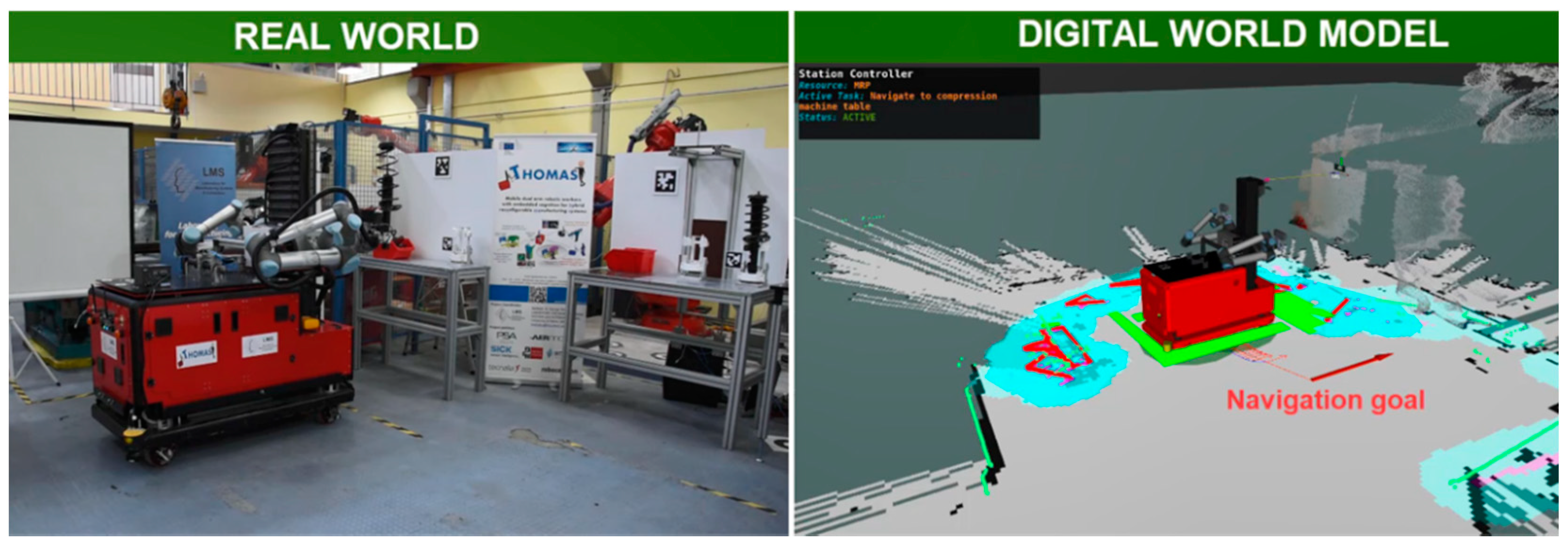
In
Figure 5, the navigation goal and the calculated path can be seen in the digital twin.
3.2.2. Virtual Docking for Accurate Localization
For an industrial mobile robot, fast and accurate localization is required. The multitude of sensor data used in modern robotics can burden the data network, and complex algorithms can enhance the computational complexity needlessly. Using only one type of sensor, such as only cameras or only laser scanners for the navigation and localization, will inevitably lead to ignoring the advantages of using multiple types of complementary sensors.
In this paper, a simple yet novel localization method based on robotic vision is proposed; the method works in tandem with the navigation algorithm that uses data collected from the laser scanners.
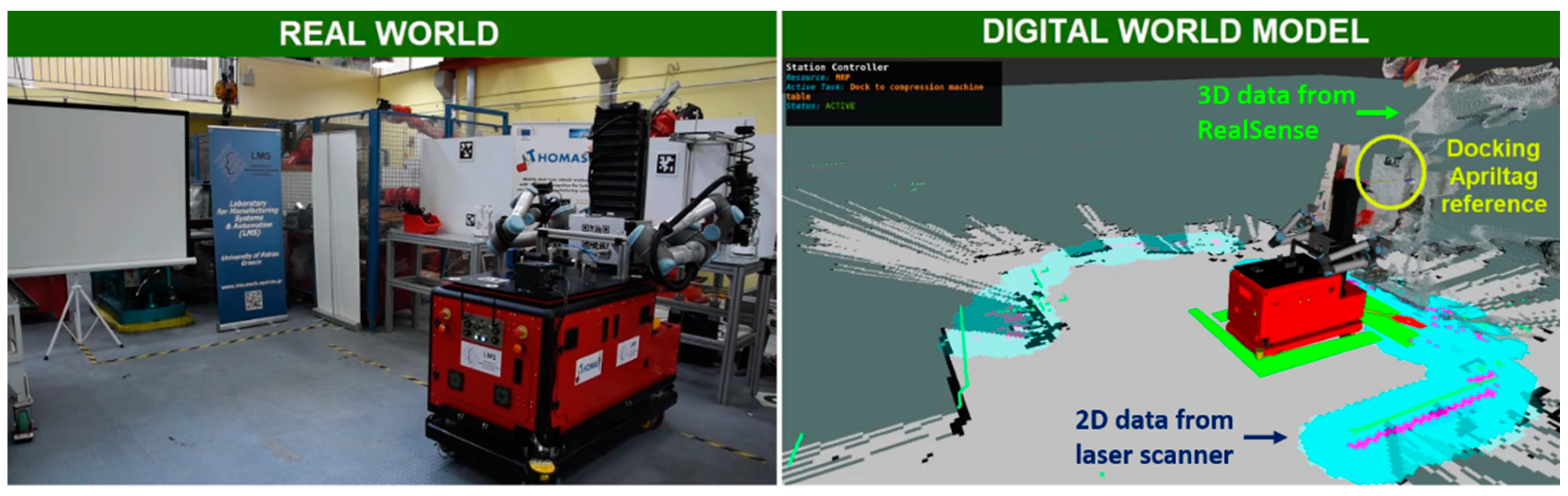
As explained in the previous subsection, the output of the navigation usually retains an error from the process. For this reason, a simple localization method was implemented after each navigation in front of workstations in order to localize the mobile robot accurately to the workstations, with a maximum error of 1 cm. This method was based on input received from a stereo camera, in particular a RealSense camera, as shown in
Figure 3. Although the camera had 3D capabilities, only 2D data was used for the localization, achieving good results with a smaller amount of data.
Specifically, the localization module was based on the detection of fiducial markers. In particular, the tag detector was tested with two different marker families: the AprilTags [
50] and the Alvar [
51]. The camera detected the corresponding tag for each workstation, and then a reference frame was created for this marker.
Using this frame, the transformation between the robot reference frame and the marker, or the position error, is calculated, and the difference was fed to a closed-loop PID velocity control, which then assigned the necessary speed to the omnidirectional wheels of the robot. The controller completed the localization when the error was under an acceptable value. The proportional, integral and derivative term values were calculated by trial and error, and set to values that completed the process in a matter of seconds but did not cause the robot to succumb to oscillations due to high speeds when the process was finishing, since due to the control, the closer the robot was to the targeted endpoint, the lower the speed was.
The accuracy for the algorithm was configurable by modifying the finishing criteria and reconfiguring the PDI values to match. This resulted in a smooth and fast localization, accurate enough for industrial standards and simple enough to implement for every robotic system that utilizes a camera system. If a marker was not deemed appropriate for the desired layout, other detection methods could be used, such as feature detection, and the output could be fed to the same PID control. An instance of the localization process as presented in the real world and the digital twin is shown in
Figure 6.
This algorithm can also be modified to be used in conavigation scenarios, for example, in the case of an AGV, to which a fiducial marker is attached. By detecting the marker, the robot was able to follow the movement of the AGV at a set distance, this time using sensor data from a monocular camera mounted on the side of the robot. The mobile conavigation is shown in
Figure 7. The conavigation allowed for the MRP to continue manipulation on mobile workstations, such as the one shown on top of the AGV in
Figure 7.
3.3. Process Perception Module
Due to a mobile robot’s movement, each time it navigates from station to station in an industrial environment, it is not guaranteed that it will dock to the same position each time in the same workstation. While the localization algorithm described above will mitigate the error, there may be a small deviation in the position that, combined with the fact that objects are not always in the exact same position on the workstation, even if they are supported by fixtures, accumulates an error that may be small but dangerous for the object, if the motions of the manipulator are preprogrammed.
Process perception methods strive to solve this issue. In this work, methods of object detection are proposed for flexible and safe manipulation. Several methods were tested with the intention of finding the most accurate for industrial applications.
Contours can be described as curves that connect continuous consecutive points in an image of the same color or intensity. Suzuki and Abe [
52] first proposed two algorithms for the extraction of contours. The first algorithm determines the relations regarding the surrounding area among the borders of a binary image. The outer and the hole (inner) borders have a unique correspondence to the connected components of l-pixels and to the holes, respectively, and the output will be a representation of a binary image, from which some sort of features can be extracted without reconstructing the image. The second algorithm is a modified version of the first, and follows only the outermost borders (i.e., the outer borders that are not surrounded by holes).
Essentially, to extract a contour, one must find sequential border points in a binary image, which are found by the difference in intensity (“1” or “0”) between them and the pixels that surround them. The use of contours reduces the computational complexity of recognition and classification, since there is no need to take into account all the pixels of the image, only the ones belonging to the contour.
For the extraction of the contours, the algorithm that was used here is a simple one. The input images from the cameras were greyscale images. A color threshold was set on these images according to the color of the object to be detected. Then edge detection was implemented. From the output of the edge detection, the contours were detected using a function built with Abe and Suzuki’s algorithms in mind. More than one contour may be detected in an image, especially if there is not a uniform background. To identify the desired object, the contours in the image must be compared with the geometrical shape of the object to be detected. Alternatively, a marker such as an AprilTag can be placed in a relatively static position compared to the fixture of the object, and the contour with the right distance from the detected marker is the right one.
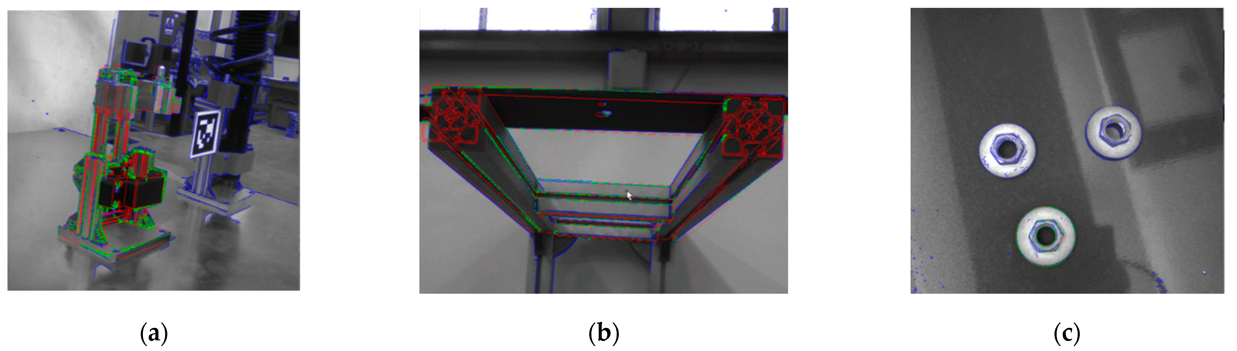
There are several disadvantages to the contour method in industrial environments. For the object to be reliably detected, the background surrounding it must be of a different color, something that is not assured in a factory. Another disadvantage is in case the cameras see in grayscale, like the ones used in this work. If the image is grayscale, then very useful models for thresholding, such as HSV, cannot be used, and the threshold and edge detection process are subpar to what they would be if the image were colored. An example of contour detection for a damper is shown in
Figure 5.
To get over the disadvantages imposed upon the contour-detection method, surface matching algorithms were tested next. Surface matching is a method of matching structures in an image. The methods developed here used correspondences between 3D point clouds in order to match similar structures in the cloud of a scene captured by a camera. These methods required a CAD model as input, from which the point cloud of the model corresponding to the desired object to be detected was extracted. For the surface matching, the iterative closest point (ICP) and point-pair feature (PPF) methods were used.
Point-pair features (PPFs) describe geometric relations between a reference point and a target point. A prominent algorithm for 3D model-to-scene matching was proposed by Drost et al. [
53], in which PPFs were used in combination with a voting scheme that found the location and pose of the object simultaneously. The iterative closest point (ICP) is an algorithm used to minimize the distance between two point clouds, in this case the point cloud of the scene and the point cloud of the model. In this algorithm, one point cloud is kept as reference, while the other is transformed to best match the reference. To minimize the distance, the transformation is revised iteratively, measuring the error, for example the sum of squared differences between the coordinates of the matched pairs. The combination of the two algorithms yields the best results.
The surface-matching approach was an improvement on the contour method, in the sense that the background of the scene and the colors of the objects were of no consequence. The surface-matching method is more prone to errors from noise and clutter. In this case, there was an error in the matching, but it appeared to be stable in each detection, and thus easily minimized by a stable corrective transformation. Using a fiducial marker in order to provide a threshold for the possible positions of the object helped mitigate the error as well. The results of the surface-matching algorithm for the detection of a damper is shown in
Figure 8b, where the orange-colored cloud represents the detected object.
4. Implementation
For the implementation of the methods described in this paper, as mentioned before, the Robot Operating System (ROS) was used [
54]. The ROS is an open-source set of software libraries and tools that are used to build robot applications. It has drivers for many devices, such as the cameras used in this work, state-of-the-art algorithms and powerful developer tools. The programming language C++ was used in the creation of the nodes responsible for process and shopfloor perception.
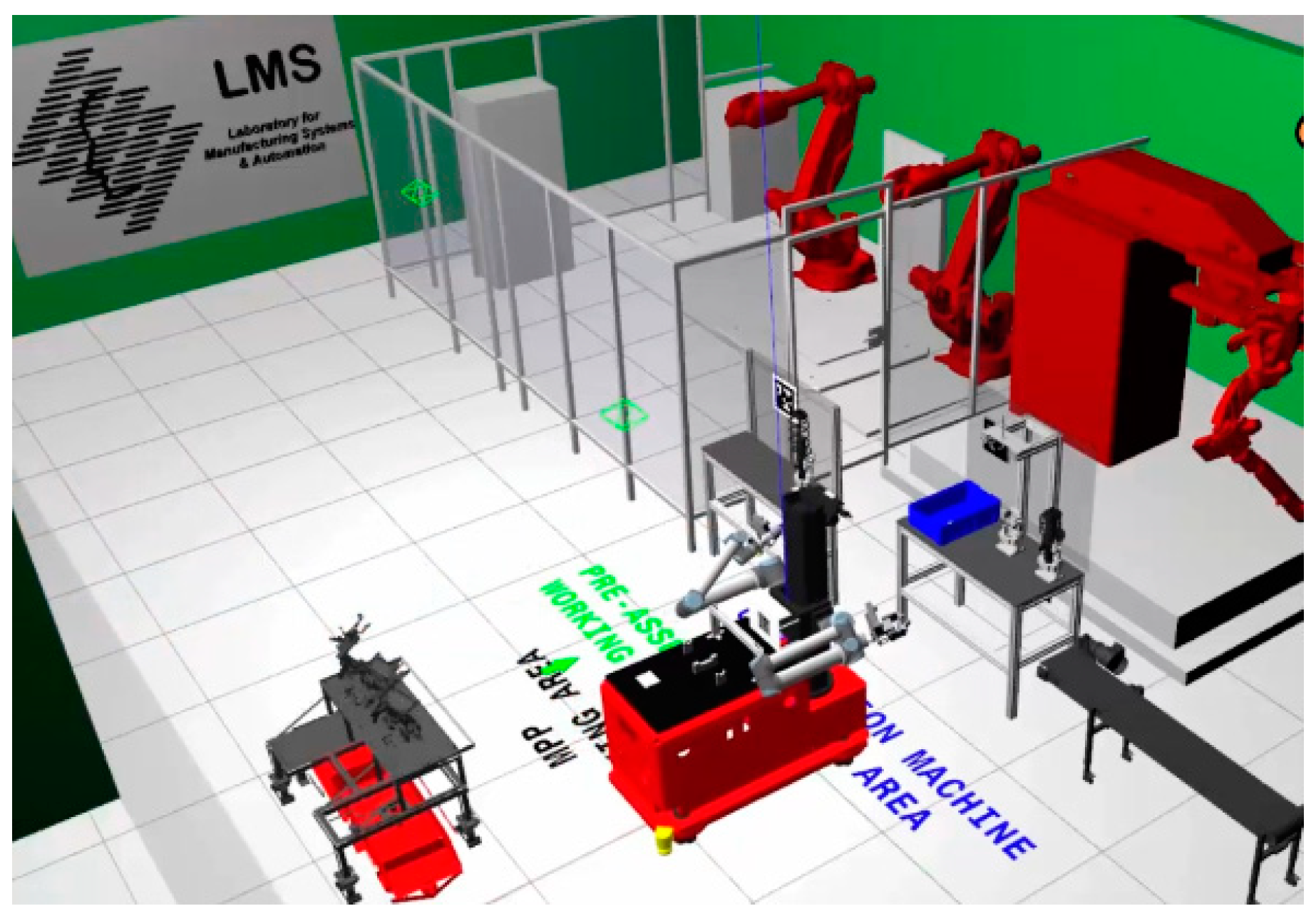
A first implementation of the following was done in a simulation to ensure the validity of the undertaking, using the Gazebo simulator [
55]. The simulation was used to test the software architecture described below and to define the requirements for the proper execution of the use case described in
Section 5, regarding all fields, localization and detection included. The simulated shopfloor is shown in
Figure 9.
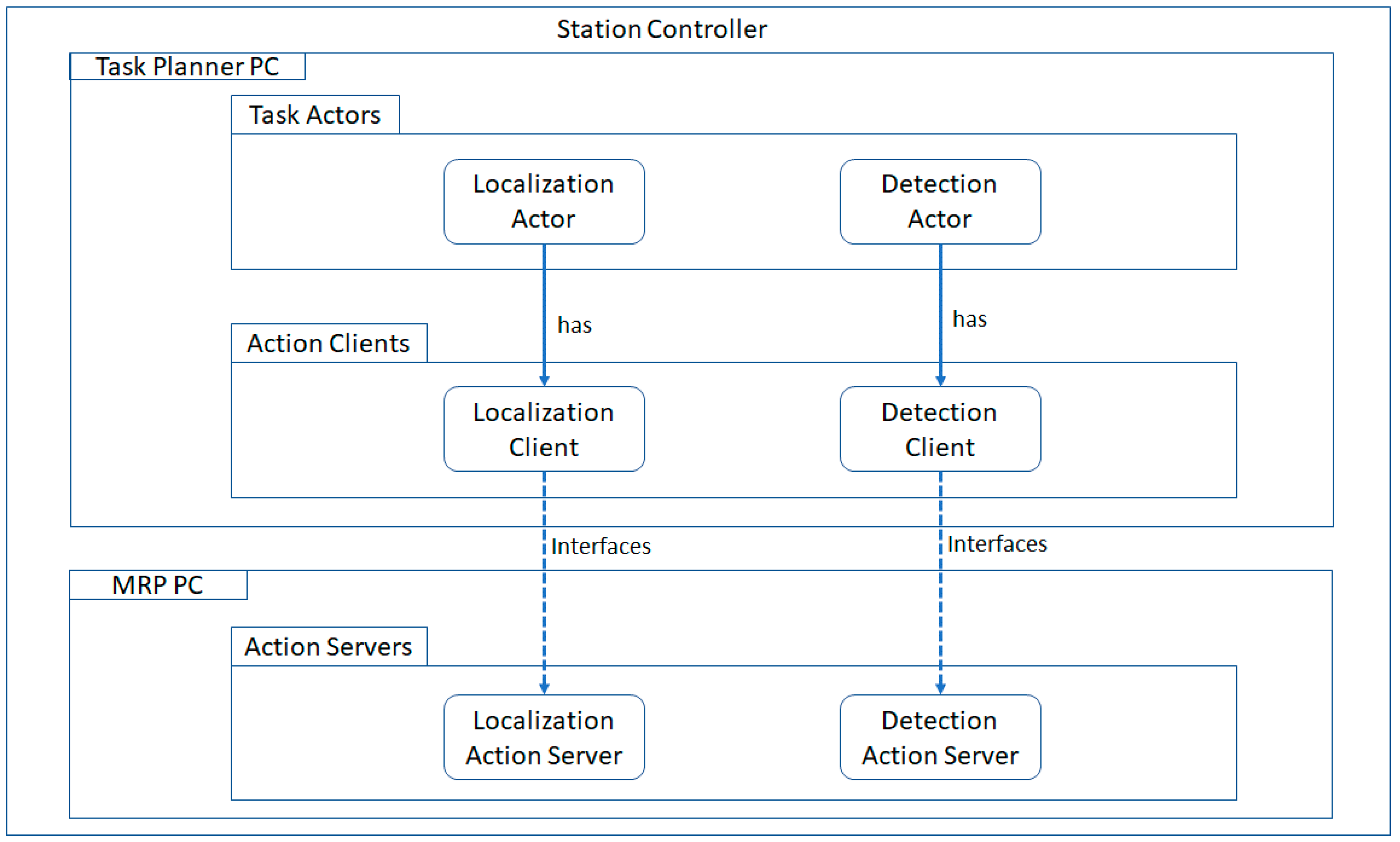
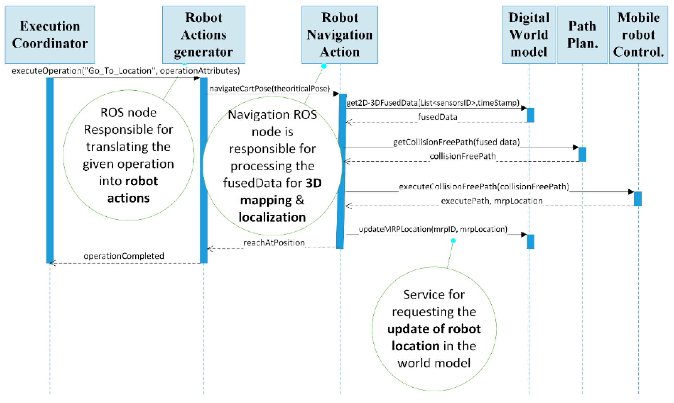
For the communication of all the modules of the robotic system, such as navigation, localization and object detection, as well as the execution and monitoring of the execution of the necessary tasks, a station controller was used. The station controller implemented the execution coordinator, which was responsible for enforcing the required sequence of tasks execution and keeping track of the new, pending and active tasks within the station controller. The station controller execution process was interactive and dynamic. In this sense, the station controller could respond to unexpected events in a coherent way that minimized the impact on the orchestrated tasks. The station controller was developed with a service-oriented approach. In this architecture, every action that is to be executed, such as the navigation action, has an action actor. For each actor, a key element for its implementation is the ROS Lib Action Client, which is capable of communicating with the related ROS Lib Action Server. The server and the client communicate via a “ROS Action Protocol” built on top of ROS messages. The architecture of the station controller regarding the localization and detection aspects is shown in
Figure 10.
The station controller used input from a task planner, which informed the controller which tasks should be executed next. The implementation of the task planner was mainly based on information about each task saved in a database. In addition, feedback from the mobile resources motion and path planners was used, given that the final goal was to minimize the time required and the distance traveled for each task execution, with a target of maintaining sustainable cycle times. As such, when the detection and localization tasks were to be executed was determined by the task planner.
The digital twin module explained in the previous section provided the infrastructure for integrating all the hardware components involved in the assembly and synthesizing all the data coming from the shopfloor under a unified common environment [
41]. The digital twin provided simplified control integration and sensor data sharing, virtual representation of the shopfloor, a unified semantic data model and real-time robot behavior adaption.
As mentioned above, for each action, an action message was sent from the action client to the server.
A visualization of this approach for the navigation is shown in
Figure 11.
The main services for the navigation were: the executeOperation service, which initiated the execution of an operation and accepted as input a Boolean that confirmed if the execution had been initiated or not. The navigateCartPose service triggered the navigation node, which returned a Boolean variable on whether the mobile robot had reached the required position. The executeCollisionFreePath was used for sending the planned path in the mobile robot for physical execution while returning the success of navigation execution, as well as the mobile robot’s new location, while the updatedMRPLocation was responsible for updating the mobile robot’s current location in the digital twin.
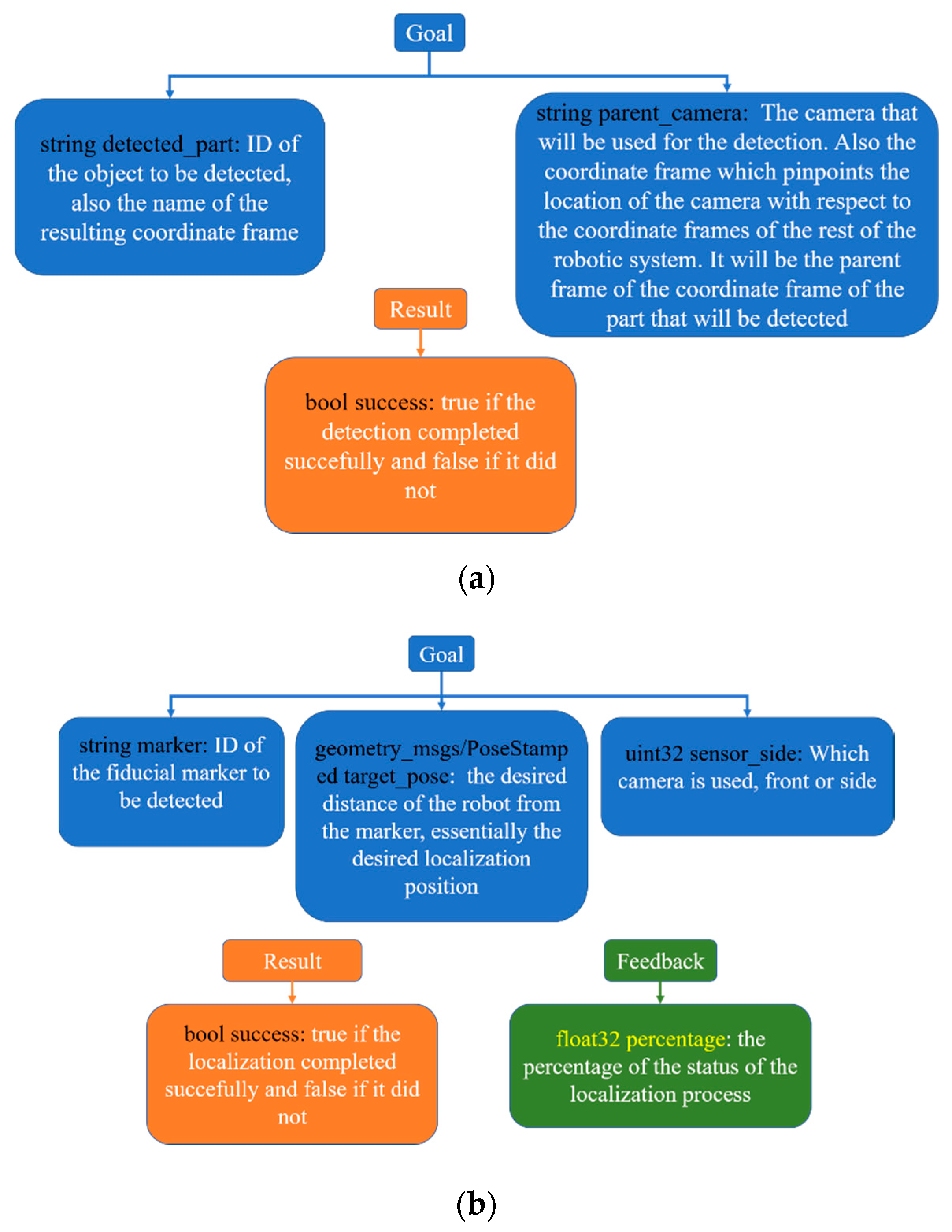
For the localization and object-detection algorithms, the action message and its services are analyzed in
Figure 12.
The action server in the object-detection instance was responsible for calling the detect service, per the client’s request. If the detection was successful, then a detected part frame was produced by the server, which was named after the detected part string that the client message sent, with the camera frame as its parent frame. This frame could then be used by different action servers, which moved the arms and were responsible for the grasping, placing or screw-fastening of the parts.
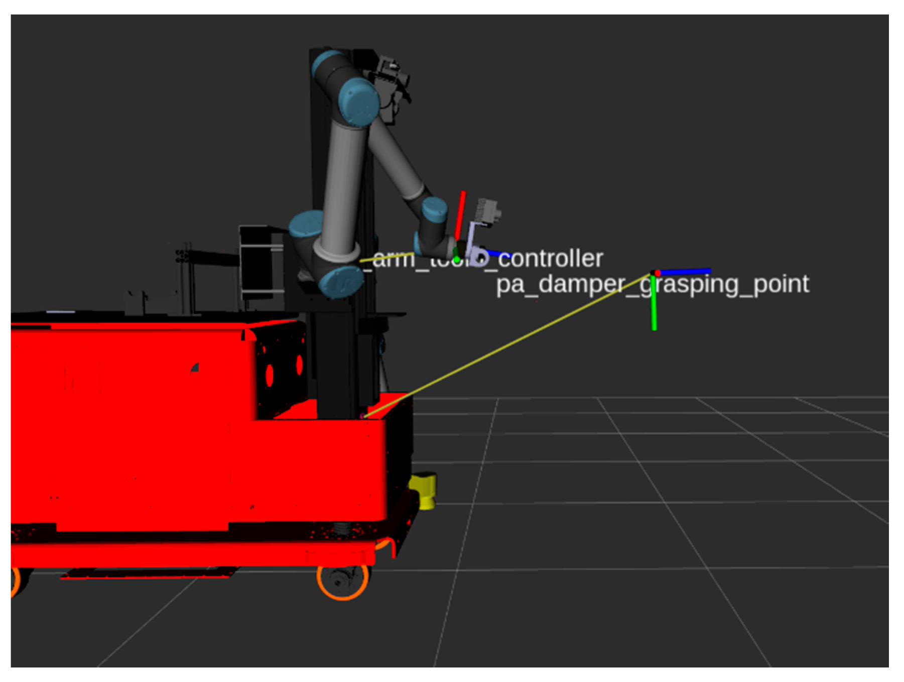
In
Figure 13, the link between the camera and the frame of the detected damper can be seen, named as the pa_damper_grasping_point, as well as the frame of the tool used for the cartesian transformation that allowed the arm to grasp the damper (right_arm_tool0_controller). By having the transformation between the frames as a known variable, provided that they are connected by a chain of links, planning frameworks such as the MoveIt Framework [
56] can be used to calculate collision-free paths for the robotic arms.
5. Automotive Case Study
The technologies discussed in this paper have been validated in an automotive vehicle’s front-axle assembly. Assemblies of this kind are manual in industry, with the human moving to different workstations and carrying objects that are heavy, causing a strain in their health and their performance. We propose the cooperation of the human operator with a mobile robot, which will allow the human to undertake easier tasks and let the robot handle the tiring tasks of heavy-object transportation. As such, in this assembly use case, a mobile robot (MRP), an AGV and a human collaborated in the completion of several tasks, such as damper preassembly, screw fastening, transportation of parts, etc. The use case aimed to present a reconfigurable fenceless shopfloor.
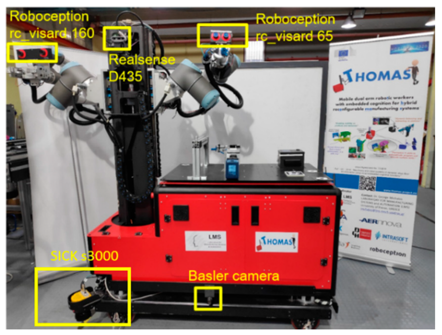
This system used a multitude of sensors. It had 4 cameras mounted, the ROBOCEPTION rc_160 in the right arm and the rc_65 in the left arm [
56]. On top of the torso of the robot, there was a RealSense D435 [
57], while on the side of the robot, there was a Basler camera [
58], as shown in
Figure 14. Aside from the cameras, the MRP also had two SICK laser scanners [
59], one in the front-left part and one in the back-right part.
The use case began with the MRP navigating to the preassembly workstation (PT), and then docking to it using the RealSense camera and an AprilTag marker using the localization process explained in
Section 3. Then, the MRP had to pick up a preassembled damper using the rc_160 camera and the detection process explained in
Section 4. Then the robot had to navigate to the compression machine (CM) and dock to it, and place the damper to the corresponding fixture by performing a detection of the fixture with the rc_65. The MRP’s next action was to manipulate an alignment rod and a nut, using the detection process to detect the nut, as well as the upper structure from which the alignment rod was picked up and on which the nut was placed. Next, the MRP had to pick up the compressed damper and navigate to the AGV station and dock there, in order to place the compressed damper. Then, the AGV and MRP conavigated, with the MRP keeping a steady distance from the AGV using mobile-docking functionality. While moving, the MRP had to perform a screw-fastening action on the moving workstation of the AGV.
During this process, the human operator also worked in the cell, moving from station to station. The robot took their presence into account with its shopfloor perception, using 2D and 3D data from the laser scanners. The tasks necessary for the assembly are also shown in
Table 1.
The detection of several parts, necessary for the completion of the described use case, is shown in
Figure 15.
It is easily surmised that the technologies regarding shopfloor and process perception presented in this work were of vital importance for the implementation of the use case. The localization process was necessary to compensate for the navigation error, in order for the robot to be in a position from which it was possible to execute the detection and manipulation actions. The detection was necessary, since the objects to be manipulated would not always be in the exact same position, so predesignated movements would not work for the manipulation. The use of this technology enhanced the reconfigurability of the assembly line.
In
Table 2, several of the processes that required detection or localization capabilities are shown in physical view and digital twin view.
6. Results
The methods for shopfloor and process perception introduced in this paper produced the following results. The navigation, although successfully completing repeatedly, had a maximum accuracy of 5–10 cm, which was too much for object manipulation at the workstations, as expected. The localization was executed repeatedly and successfully by the robot, decreasing the error to 1 cm or less. The average time of the localization was 8 s.
The detection method presented enabled the successful manipulation of objects after navigation of the robot without damaging the parts every time the execution was repeated. In addition, the time that it took for the detection pipeline to be executed was below 1 s. Including the movements of the arms, the time for the completion of several pick-and-place operations in the case study are shown in
Table 3, in comparison to the time it would take to manually teach each process.
From the results, it is easy to deduce that the automatic method that used detection was much more time-efficient. Let it be noted, however, that the manual teaching time was measured for comparison only in the case of the mobile robot. In a mobile robot, manual teaching methods are not useful, since every time, due to the small deviations in object and platform locations, it would be dangerous to the objects.
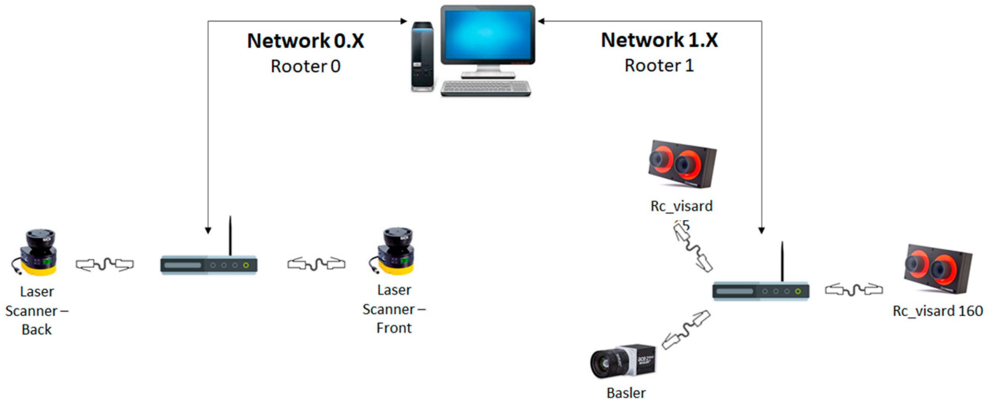
Another point to consider when using multiple sensors is the impact of the streamed data to the performance of the network, and by extension to the GigE cameras. The topology of the network concerning the sensors is shown in
Figure 16. The RealSense camera was not included, as it was a USB camera.
Because the cameras had to be connected to the same router, there were issues when all of them were enabled. In this work, several configurations were tested, in which any combination of cameras was enabled at the same time. The configurations are shown in
Table 4, where the FPS of the cameras indicated in the first column are shown when the camera indicated in the first row was enabled at the same time.
When analyzing these results, it was evident that the Basler camera was impacted greatly when the RC cameras were enabled, but not when the RealSense camera was enabled. That seems natural, since the RC cameras and Basler were all GigE cameras, while RealSense was connected via USB. As such, the RealSense camera did not affect the network at all. To overcome the above issue, a programming node was created to enable and disable the cameras in order to only have one GigE camera enabled each time a task required it.
Aside from the Basler camera, the stream of the GigE cameras, especially the RC cameras, which were stereo cameras and streamed a large quantity of data, including point clouds, affected the whole network, disrupting the function of other connections such as Modbus or the ethernet connections of the robotic arms. The cameras were isolated to one network separate from other sensors and devices to overcome this issue.
7. Discussion
Shopfloor and process perception are an important part of mobile robotics in industry. Autonomy in mobile robots requires a robot to be aware of its surroundings, especially while moving, and to be able to complete tasks autonomously and with great accuracy.
Working on this concept, novel methods for these topics, specifically for localization and object detection, and a framework for their integration in the overall robotic system were introduced in this work.
The localization method is an easy and cheap method to implement, requiring only a camera, which does not have to be stereo. Even though the one used here, the RealSense D435, is a stereo camera, no depth information for the localization was used. A pinhole camera would have been enough. The algorithm also does not require great complexity, being a PID control, which publishes the overall velocity to the robot’s motors through ROS topics, without the need to control each motor separately, its simplicity being an advantage over existing localization techniques, which are complex to implement. It is accurate enough to make object detection possible repeatedly after the movement of the platform.
From the results, it was evident that the object detection was sufficient to provide full autonomy to the manufacturing process, and fast enough to not slow down the manufacturing process, especially considering that the efficiency of the robot did not decline with time, as the human operator’s efficiency did due to fatigue.
These methods were enabled only by their integration to the robotic system through the station controller framework. This framework acted as an intermediary between the task planner, the resources and the modules of the execution, and enabled the synergy of the shopfloor and perception methods.
This integration leads to the enhancement of autonomy and flexibility in fenceless robotic shells, eliminating time-consuming and difficult teaching procedures. Moreover, the uncertainty in the cell is no longer a stopping block for production, since those methods bypass the need for absolute certainty.
The system was validated in a case study implemented in the automotive industry, for a car’s front-axle assembly. Future work will include testing more methods for process perception and combining them to achieve reliable results, extending the deployment of the application in additional industrial sectors.


 ,
, 


