
Semi-Active Control for a Helicopter with Multiple Landing Gears Equipped with Magnetorheological Dampers


Abstract
1. Introduction
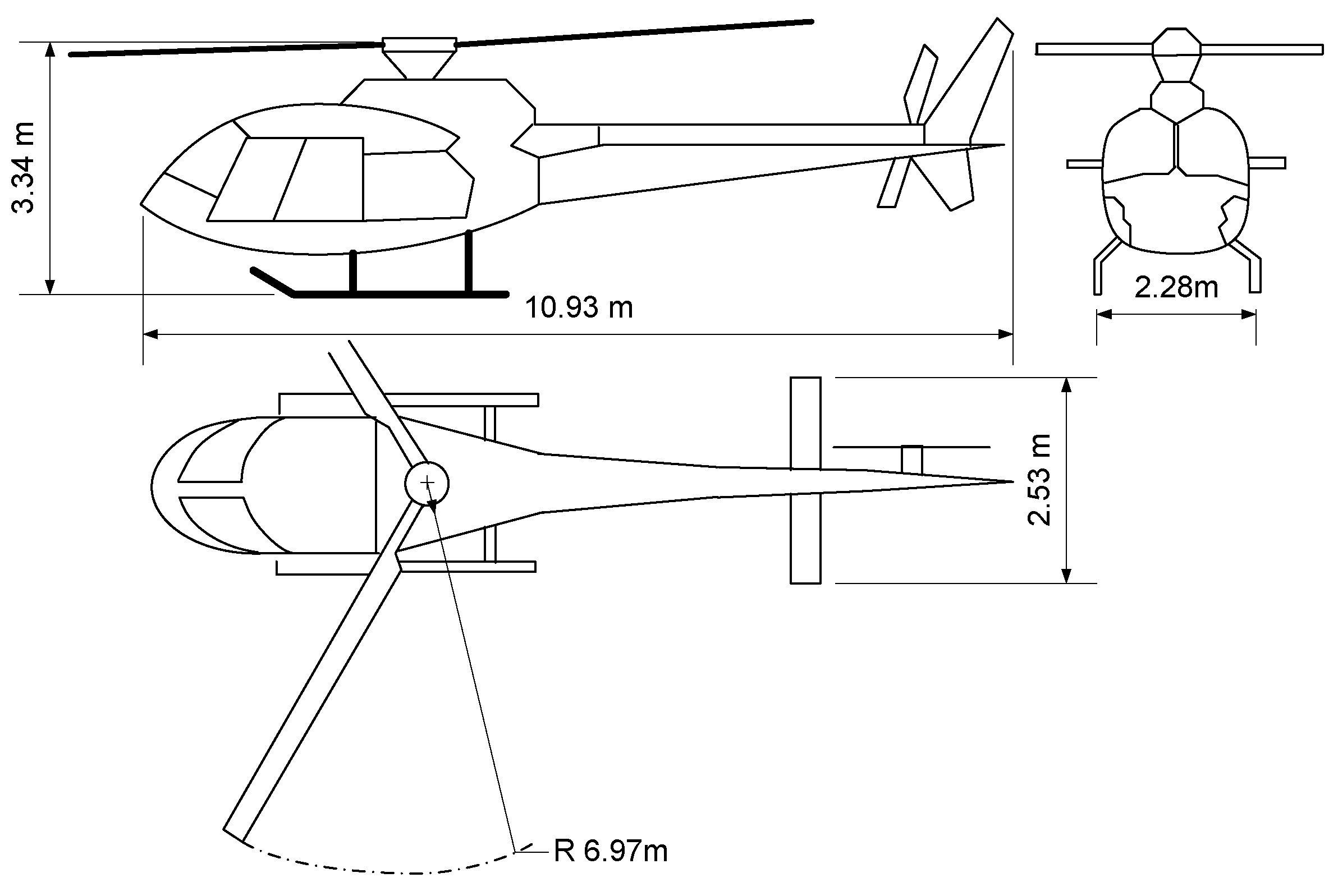
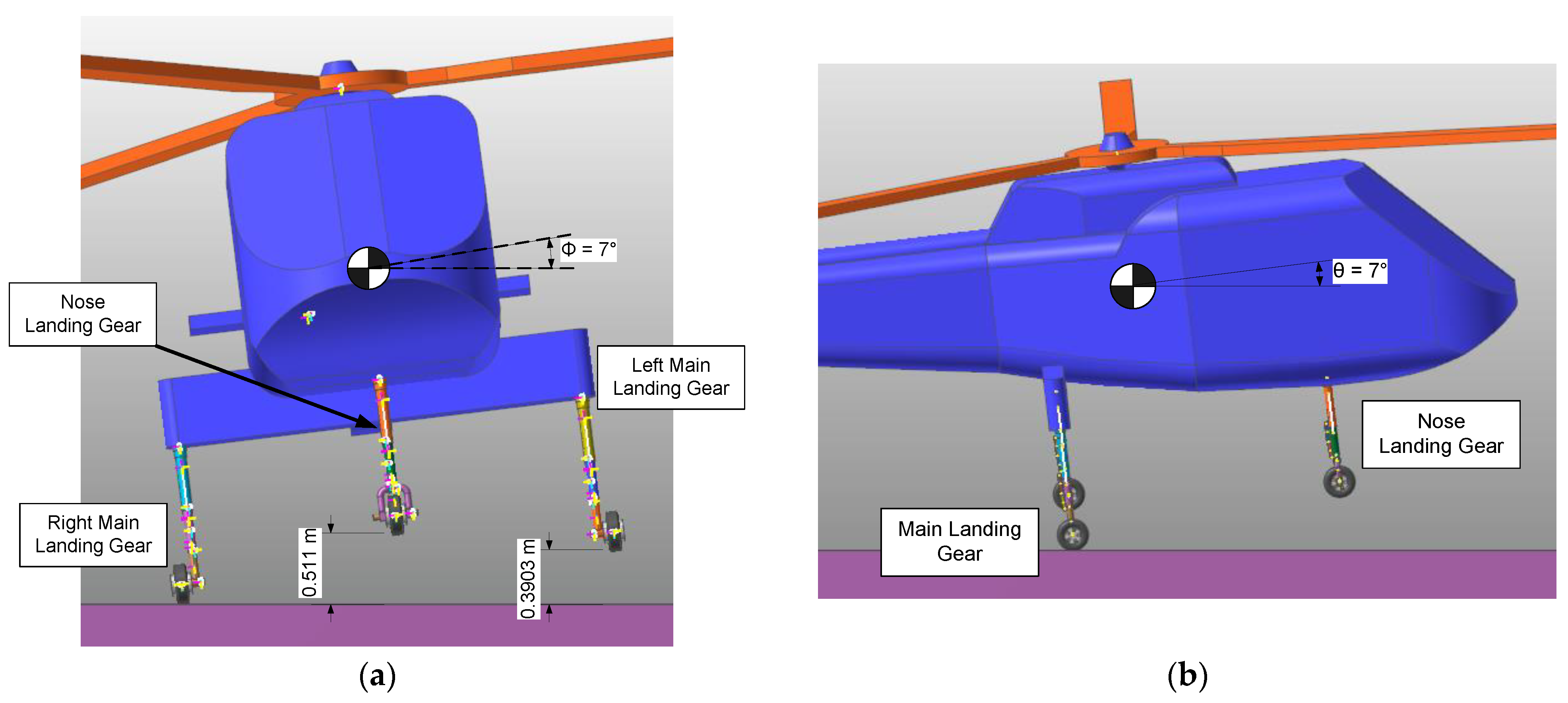
2. A Helicopter with Multiple Landing Gears
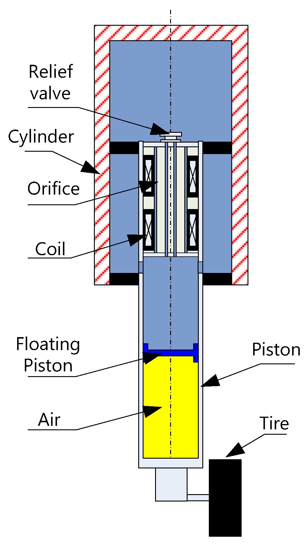
3. Landing Gear System of the Helicopter
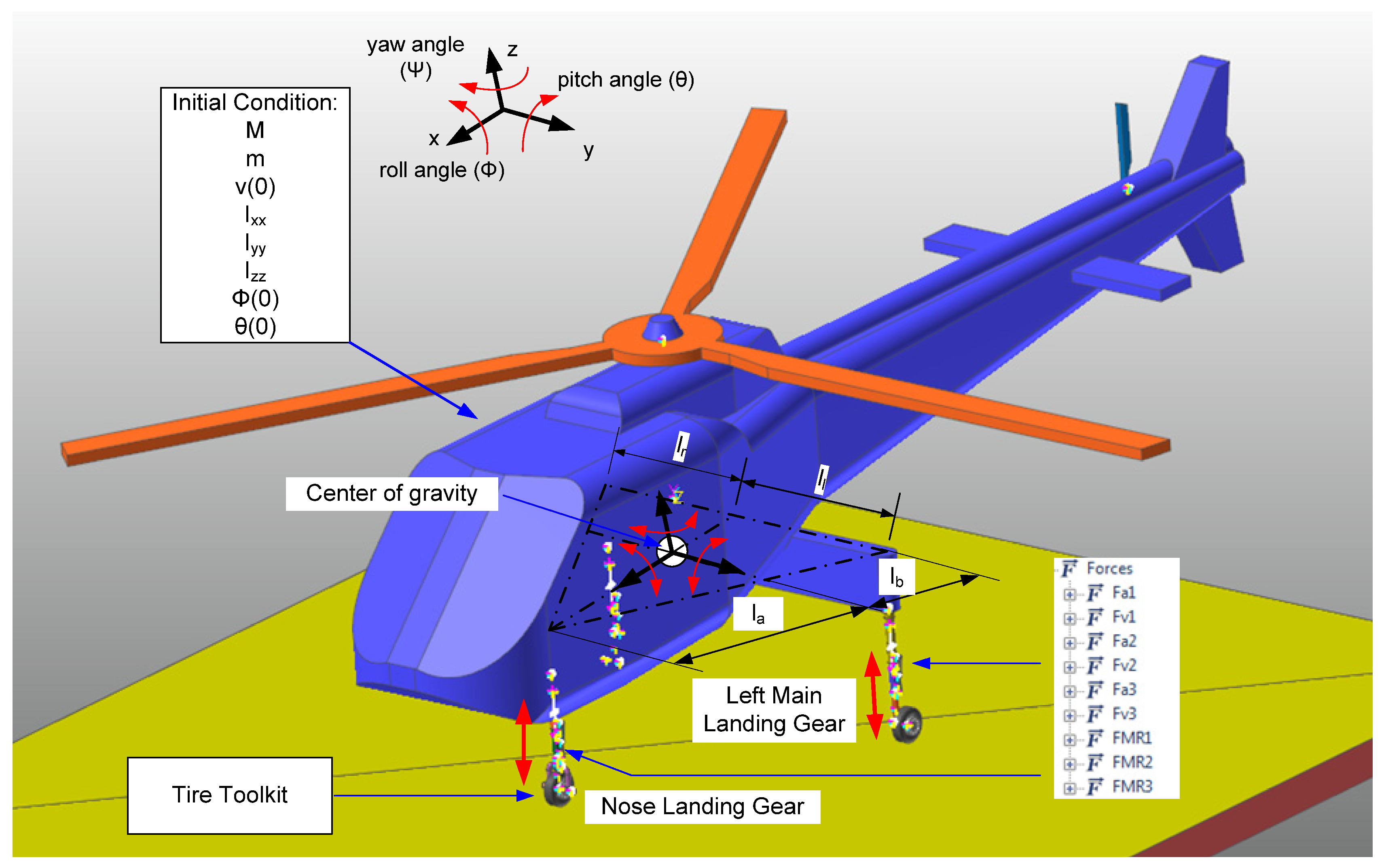
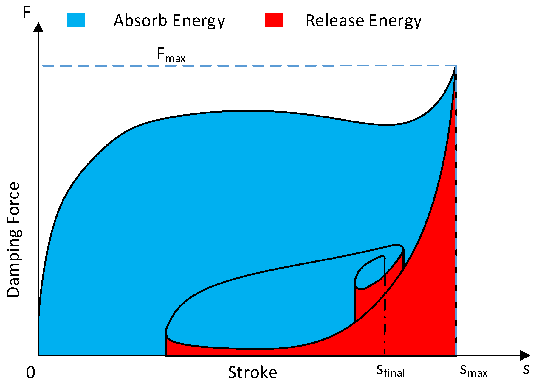
4. Control Target
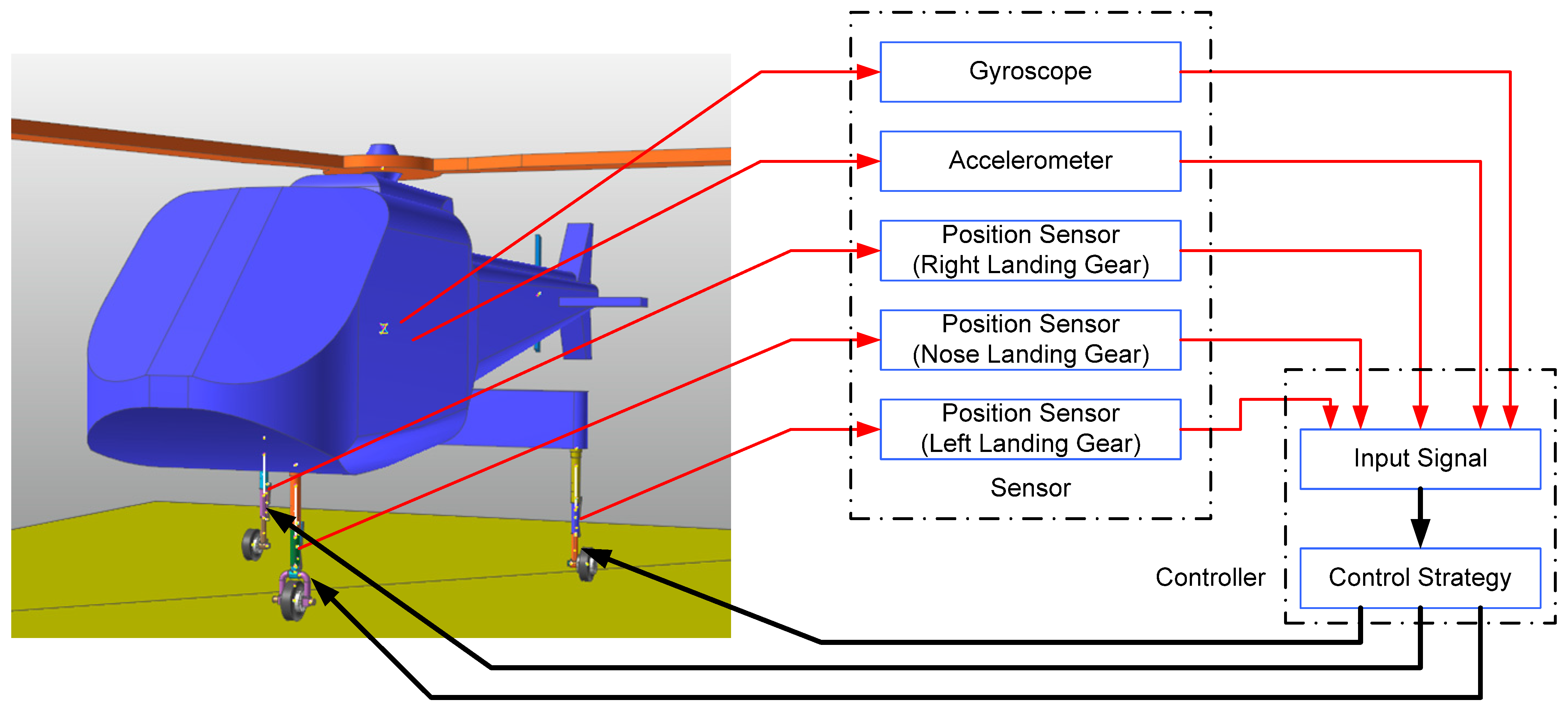
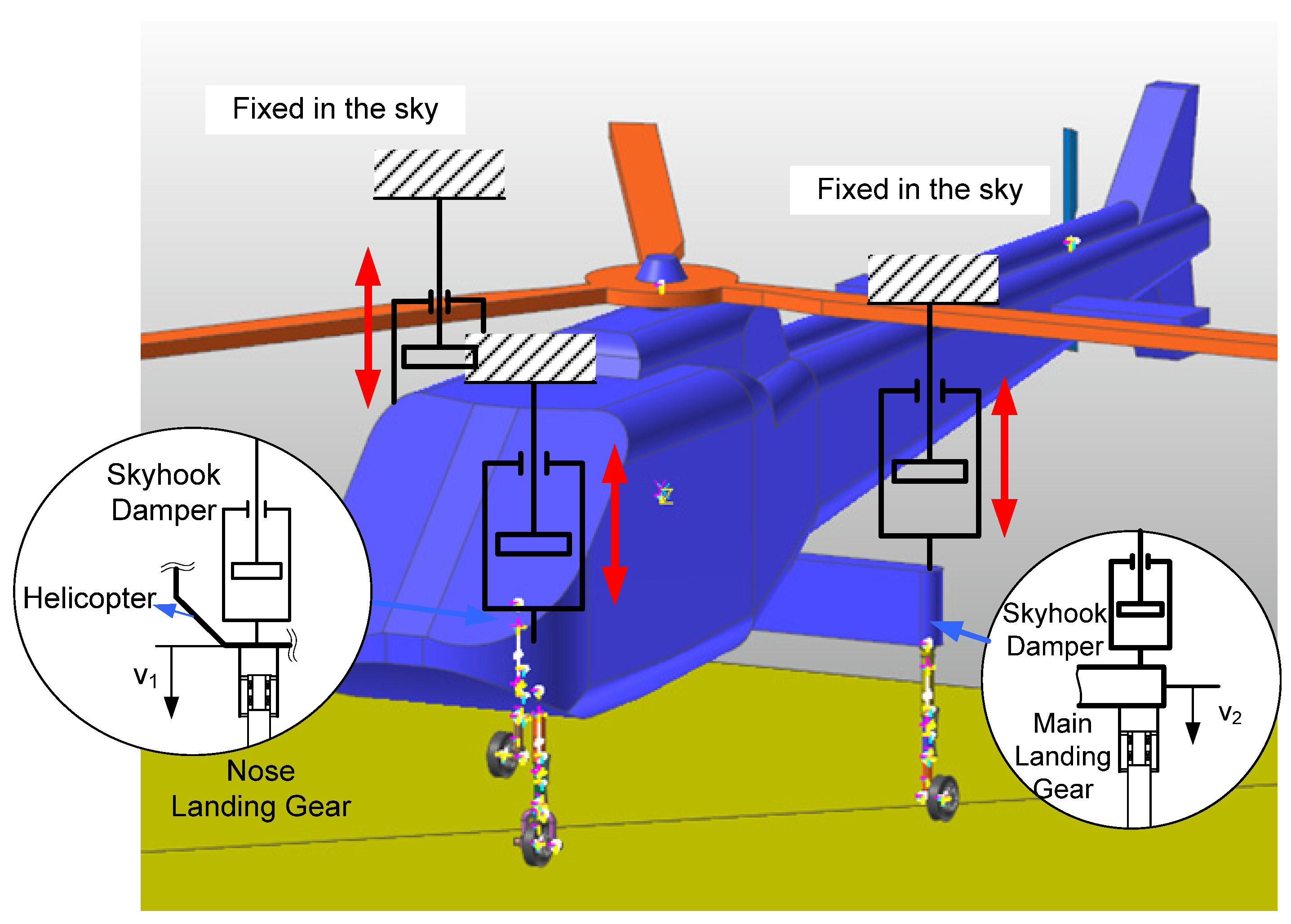
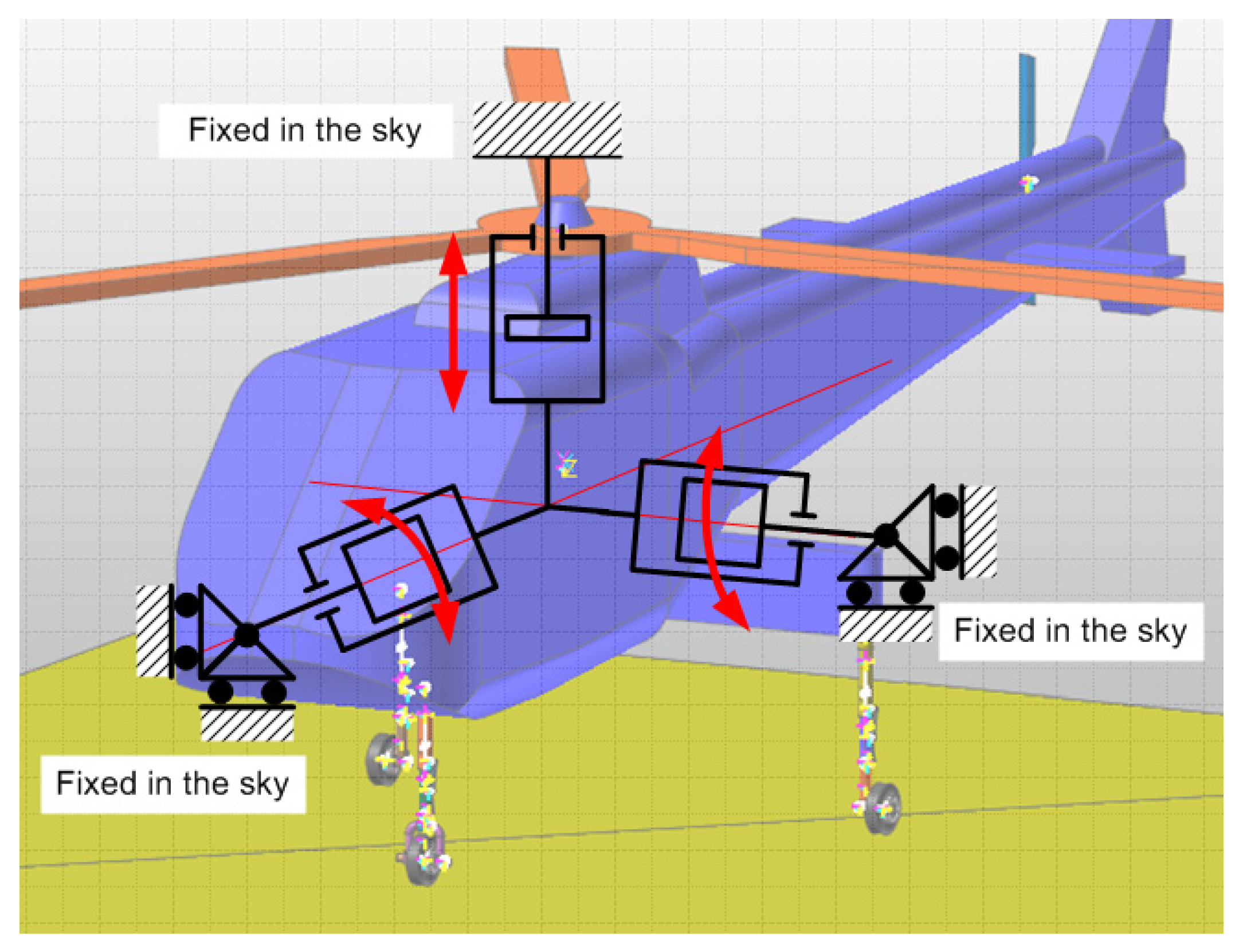
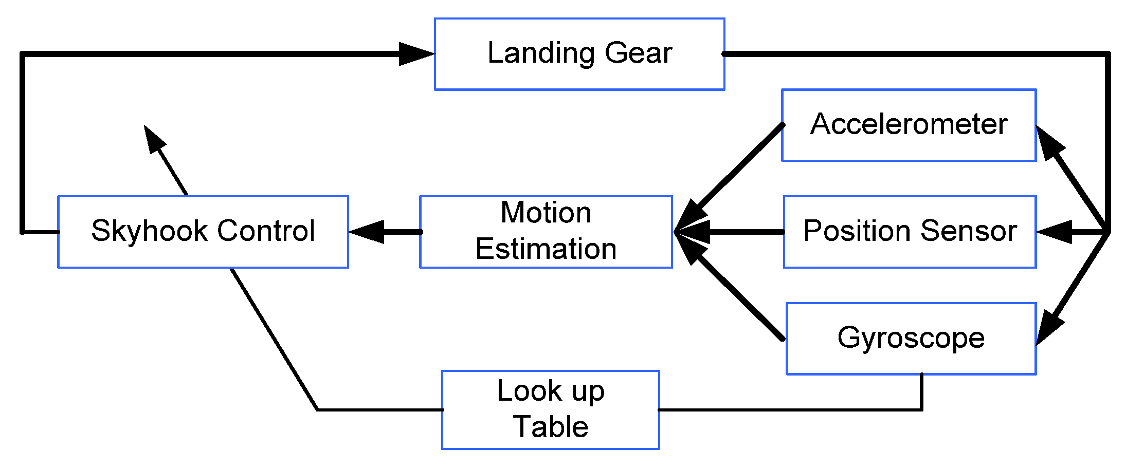
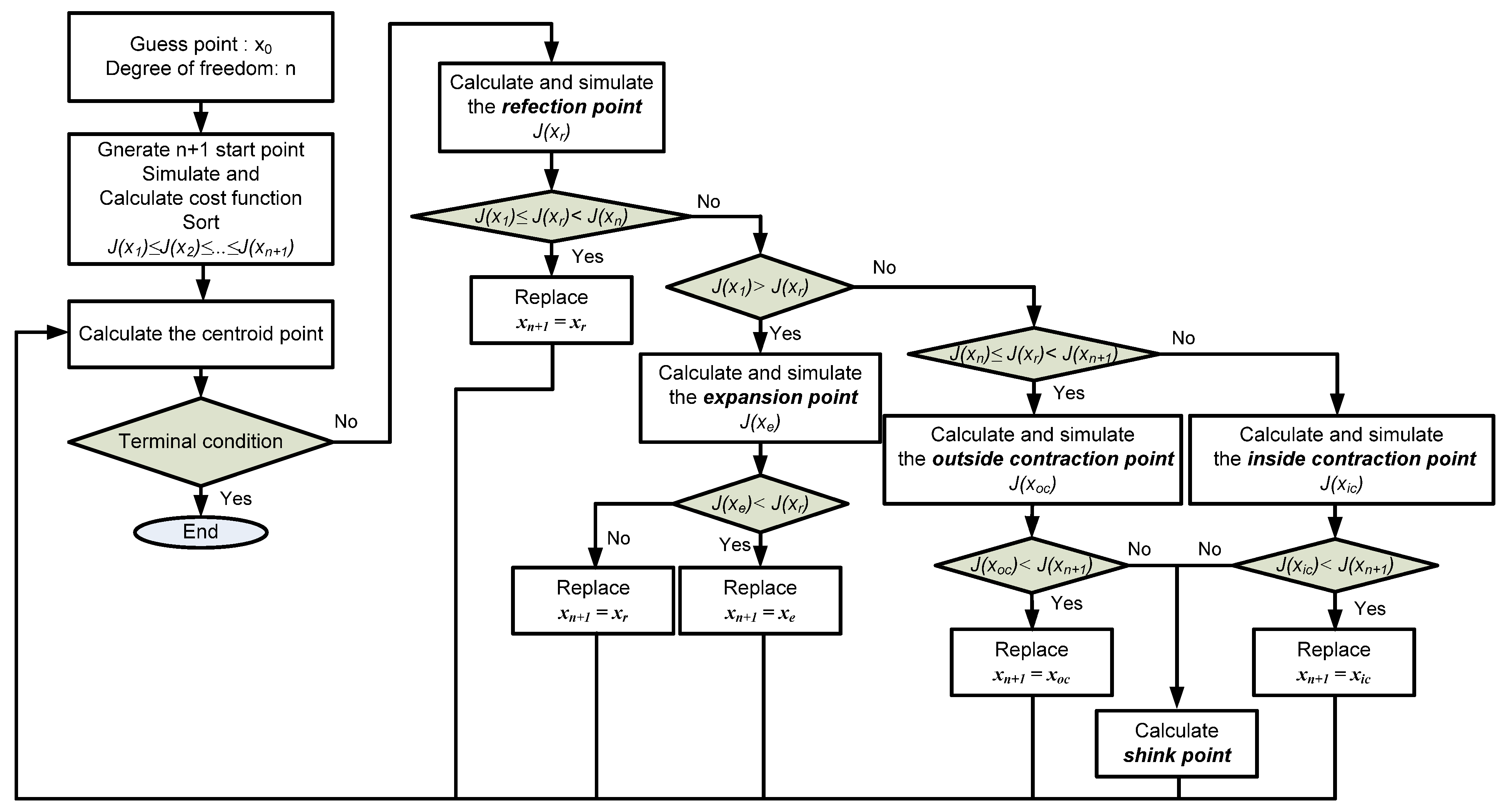
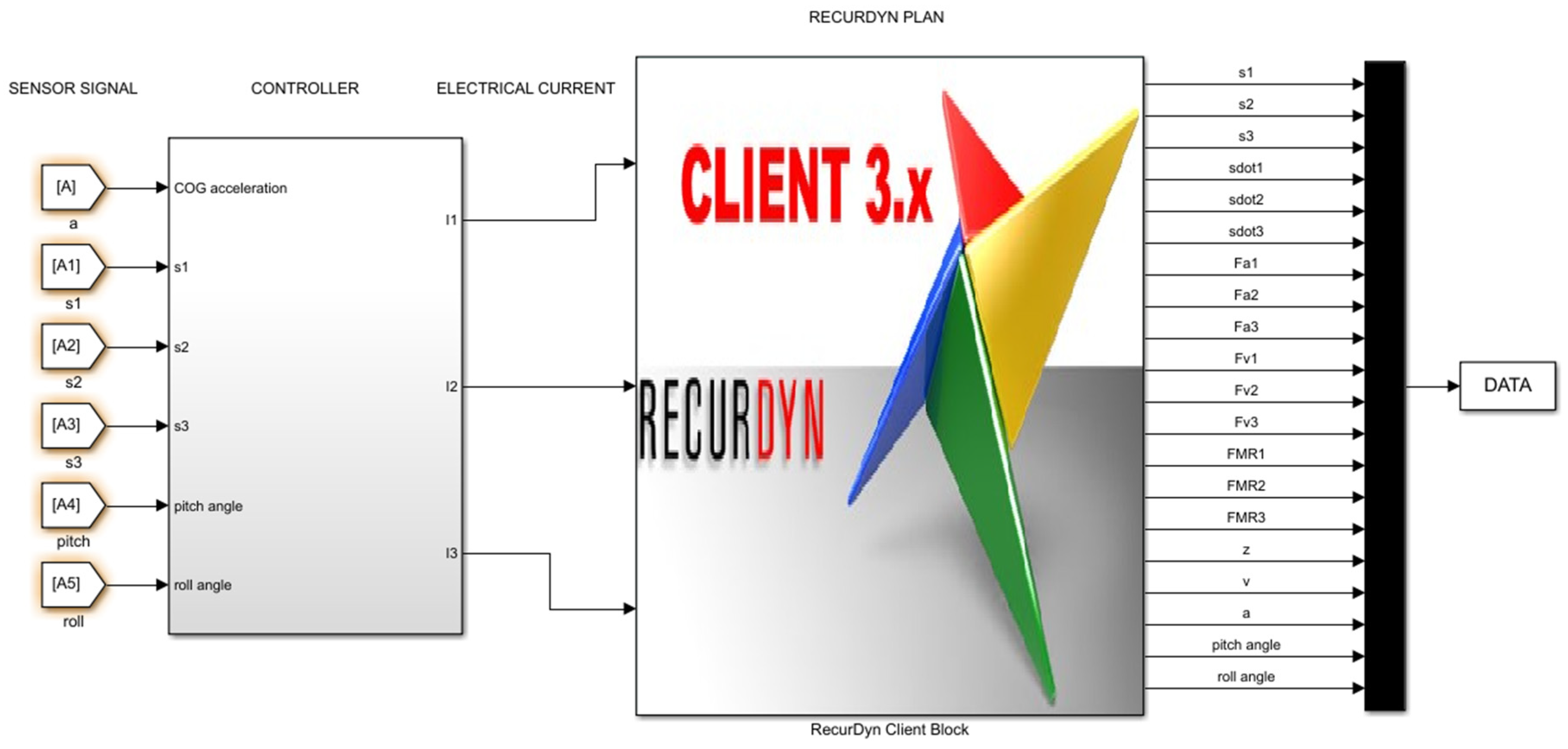
5. Control Design
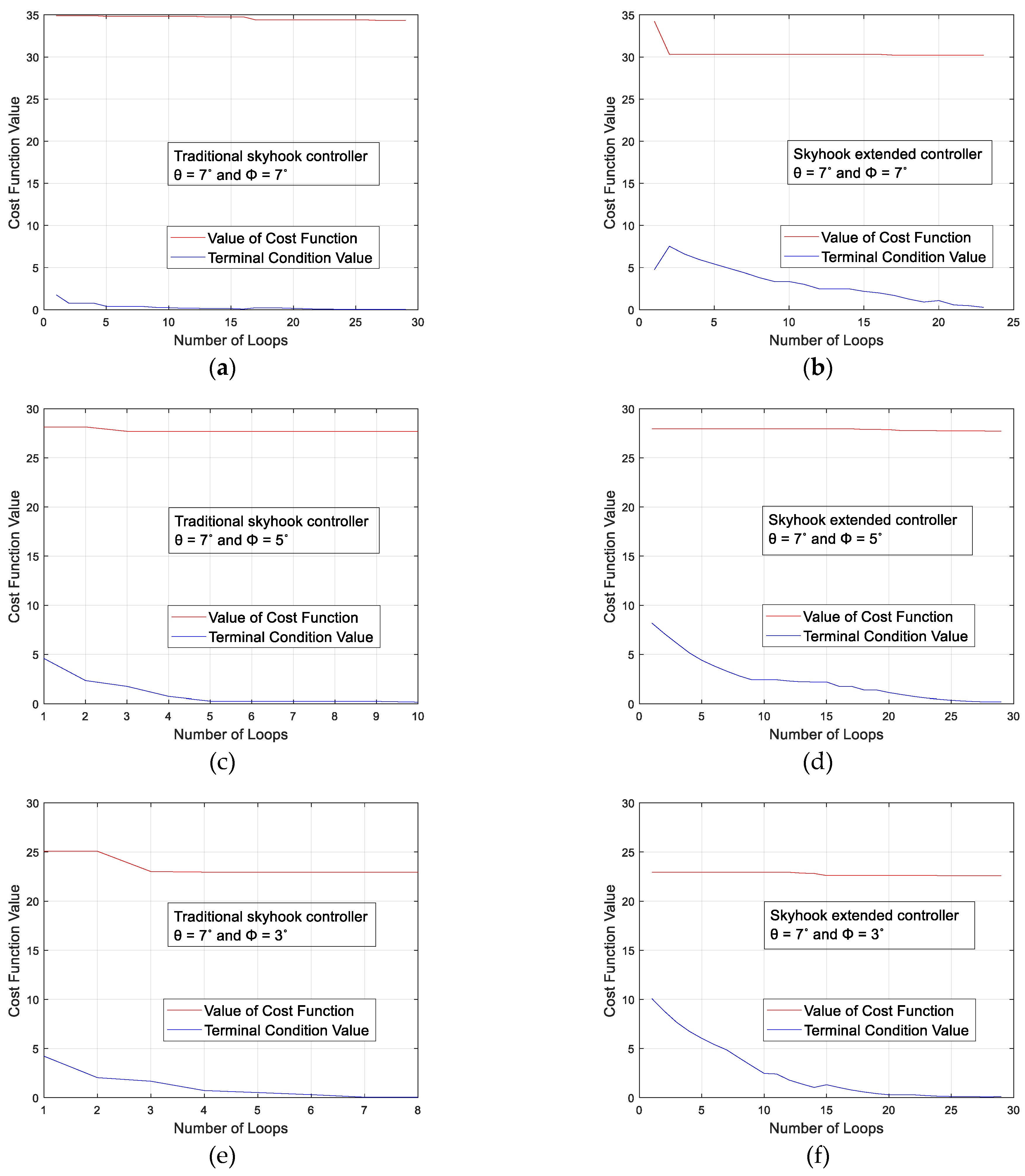
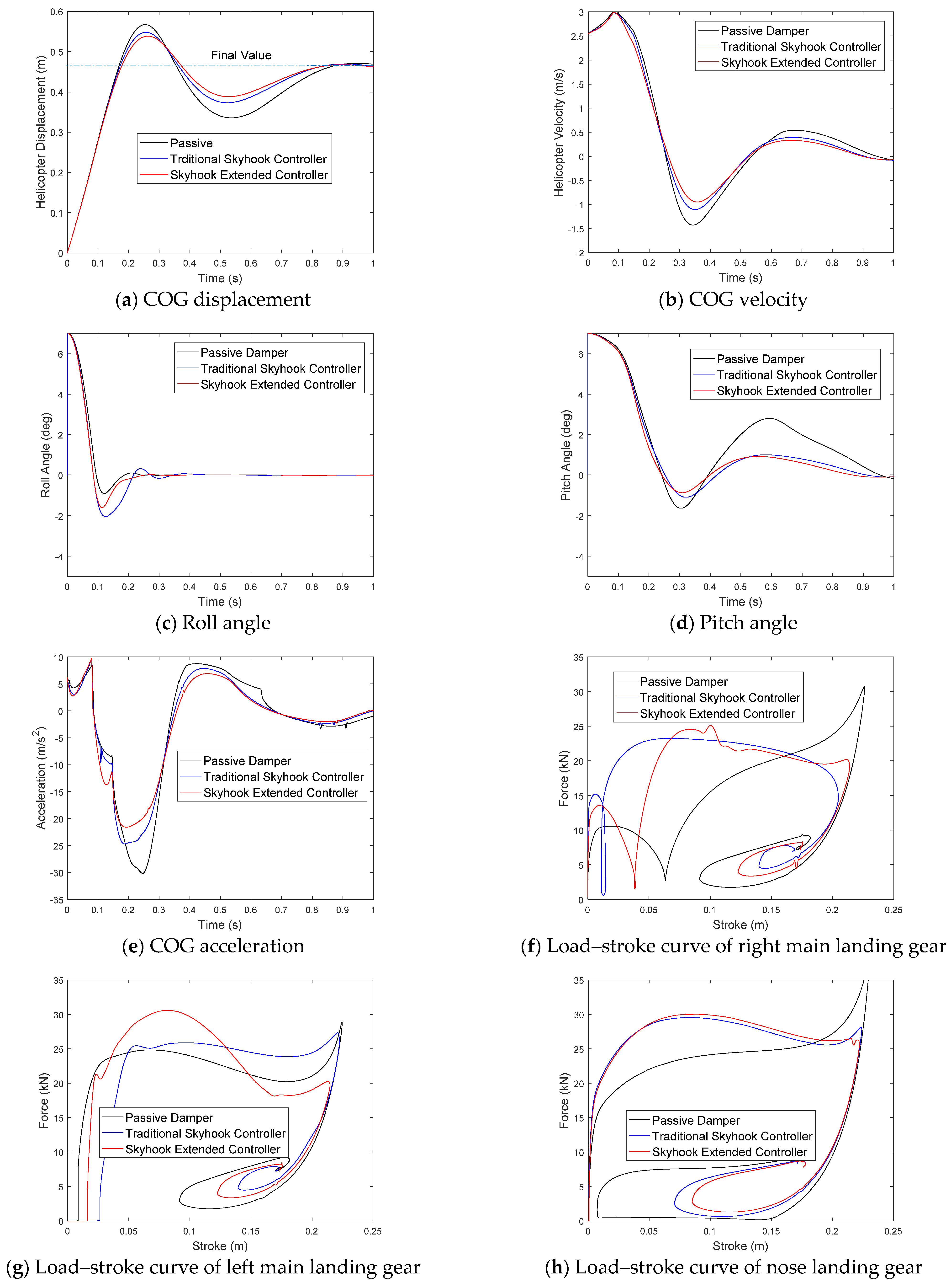
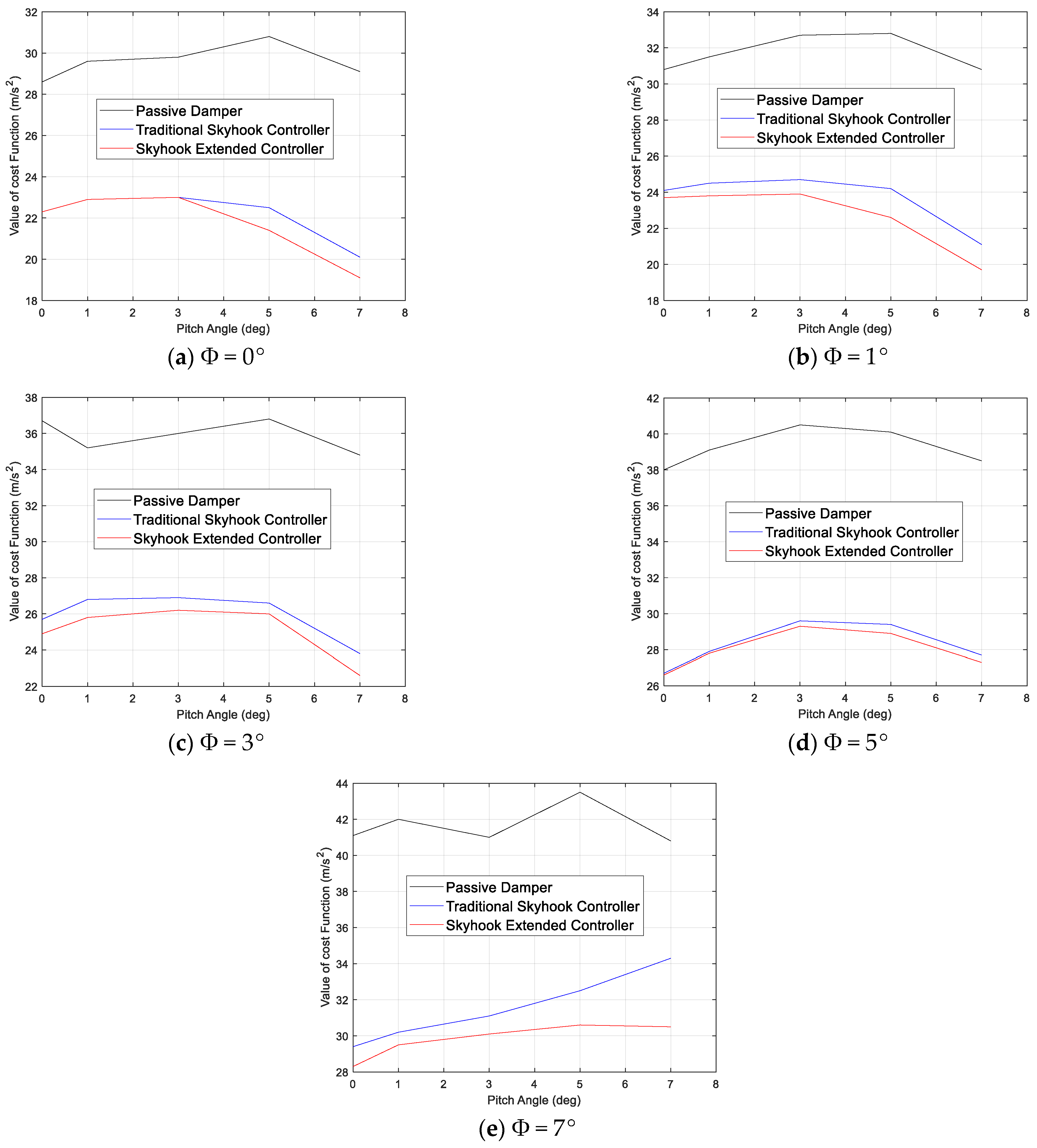
6. Simulation Results
7. Conclusions
Author Contributions
Funding
Institutional Review Board Statement
Informed Consent Statement
Acknowledgments
Conflicts of Interest
References
- Rotaru, C.; Todorov, M. Helicopter Flight Physics. In Flight Physics—Models, Techniques and Technologies; Volkov, K., Ed.; IntechOpen: London, UK, 2018; ISBN 978-953-51-3807-5. [Google Scholar]
- Wagtendonk, W.J. Principles of Helicopter Flight; Aviation Supplies and Academics, Inc.: Newcastle, WA, USA, 2015; ISBN 978-1-61954-299-0. [Google Scholar]
- Cheng, M.; Chen, Z. Semi-Active Helicopter Ground Resonance Suppression Using Magnetorheological Technology. In Proceedings of the ASME 2017 Conference on Smart Materials, Adaptive Structures and Intelligent Systems, Snowbird, UT, USA, 18–20 September 2017; p. V002T03A015. [Google Scholar] [CrossRef]
- Federal Aviation Administration (FAA). Helicopter Instructor’s Handbook; U.S. Department of Transportation Federal Aviation Administration: Washington, DC, USA, 2012.
- Hwang, J.-U.; Hwang, J.-H.; Bae, J.-S.; Hyun, Y.-O.; Lim, K.-H.; Kim, D.-M.; Kim, T.-W. Semi-Active Control of Helicopter Landing Gear Using Magneto-Rheological Damper. J. Korean Soc. Aeronaut. Space Sci. 2008, 36, 346–351. [Google Scholar] [CrossRef]
- Saleh, M. Analysis, Design Optimization, and Semi-Active Control of Skid Landing Gear Featuring Bi-Fold Magnetorheological Dampers. Ph.D. Thesis, Concordia University, Montréal, QC, Canada, 2017. [Google Scholar]
- Powell, L.A.; Hu, W.; Wereley, N.M. Magnetorheological Fluid Composites Synthesized for Helicopter Landing Gear Applications. J. Intell. Mater. Syst. Struct. 2013, 24, 1043–1048. [Google Scholar] [CrossRef]
- Choi, Y.-T.; Robinson, R.; Hu, W.; Wereley, N.M.; Birchette, T.S.; Bolukbasi, A.O.; Woodhouse, J. Analysis and Control of a Magnetorheological Landing Gear System for a Helicopter. J. Am. Helicopter. Soc. 2016, 61, 1–8. [Google Scholar] [CrossRef]
- Han, C.; Kim, B.-G.; Choi, S.-B. Design of a New Magnetorheological Damper Based on Passive Oleo-Pneumatic Landing Gear. J. Aircr. 2018, 55, 2510–2520. [Google Scholar] [CrossRef]
- Guglielmino, E.; Sireteanu, T.; Stammers, C.W.; Ghita, G.; Giuclea, M. Semi-Active Suspension Control; Springer: London, UK, 2008; ISBN 978-1-84800-230-2. [Google Scholar]
- Kashem, S.; Nagarajah, R.; Ektesabi, M. Vehicle Suspension Systems and Electromagnetic Dampers; Springer Tracts in Mechanical Engineering; Springer: Singapore, 2018; ISBN 978-981-10-5477-8. [Google Scholar]
- Kiefer, J.; Ward, M.; Costello, M. Rotorcraft Hard Landing Mitigation Using Robotic Landing Gear. J. Dyn. Syst. Meas. Control 2016, 138, 031003. [Google Scholar] [CrossRef]
- AS 550 Fennec. Available online: https://fas.org/man/dod-101/sys/ac/row/fennec.htm (accessed on 22 October 2020).
- Federal Aviation Administration. Part 27—Airworthiness Standards: Normal Category Rotorcraft. Available online: https://www.law.cornell.edu/cfr/text/14/27.725#:~:text=%C2%A7%2027.725%20Limit%20drop%20test.&text=(2)%20Any%20lesser%20height%2C,in%20normal%20power%2Doff%20landings (accessed on 10 February 2021).
- Han, C.; Kang, B.-H.; Choi, S.-B.; Tak, J.M.; Hwang, J.-H. Control of Landing Efficiency of an Aircraft Landing Gear System with Magnetorheological Dampers. J. Aircr. 2019, 56, 1980–1986. [Google Scholar] [CrossRef]
- Luong, Q.V.; Jang, D.-S.; Hwang, J.-H. Intelligent Control Based on a Neural Network for Aircraft Landing Gear with a Magnetorheological Damper in Different Landing Scenarios. Appl. Sci. 2020, 10, 5962. [Google Scholar] [CrossRef]
- Luong, Q.V.; Jang, D.-S.; Hwang, J.-H. Robust Adaptive Control for an Aircraft Landing Gear Equipped with a Magnetorheological Damper. Appl. Sci. 2020, 10, 1459. [Google Scholar] [CrossRef]
- Choi, S.-B.; Han, Y.-M. Magnetorheological Fluid Technology Applications in Vehicle Systems, 1st ed.; Taylor & Francis Group: Abingdon-on-Thames, UK, 2012; ISBN 978-0-429-11055-9. [Google Scholar]
- Currey, N.S. Aircraft Landing Gear Design: Principles and Practices; AIAA Education Series; AIAA: Reston, VA, USA, 1988; ISBN 0930403. [Google Scholar]
- Yazici, H.; Sever, M. Active Control of a Non-Linear Landing Gear System Having Oleo Pneumatic Shock Absorber Using Robust Linear Quadratic Regulator Approach. Proc. Inst. Mech. Eng. Part G J. Aerosp. Eng. 2018, 232, 2397–2411. [Google Scholar] [CrossRef]
- Dong, X.M.; Xiong, G.W. Vibration Attenuation of Magnetorheological Landing Gear System with Human Simulated Intelligent Control. Math. Probl. Eng. 2013, 2013, 1–13. [Google Scholar] [CrossRef]
- Karnopp, D.; Crosby, M.J.; Harwood, R.A. Vibration Control Using Semi-Active Force Generators. J. Eng. Ind. 1974, 96, 619–626. [Google Scholar] [CrossRef]
- Lee, D.Y.; Nam, Y.J.; Yamane, R.; Park, M.K. Performance Evaluation on Vibration Control of MR Landing Gear. J. Phys. Conf. Ser. 2009, 149, 012068. [Google Scholar] [CrossRef]
- Larson, J.; Menickelly, M.; Wild, S.M. Derivative-Free Optimization Methods. Acta Numer. 2019, 28, 287–404. [Google Scholar] [CrossRef]
- Conn, A.R.; Vicente, L.N.; Scheinberg, K. Introduction to Derivative-Free Optimization; MPS-SIAM Series on Optimization; Society for Industrial and Applied Mathematics: Philadelphia, PA, USA; ISBN 978-0-89871-668-9.
- Gao, F.; Han, L. Implementing the Nelder-Mead Simplex Algorithm with Adaptive Parameters. Comput. Optim. Appl. 2012, 51, 259–277. [Google Scholar] [CrossRef]


| Symbol | Quantity | Value | Unit |
|---|---|---|---|
| Ap | Cross-area of the head piston | 2.6 × 10⁻³ | m2 |
| b | Tire force index | 1.13 | |
| C | Viscous damping coefficient | 7.0 | kNs/m |
| g | Gravitational acceleration | 9.81 | m/s2 |
| M | Sprung mass (helicopter mass) | 2250 | kg |
| m | Un-sprung mass | 18 * | kg |
| n | Polytropic process index | 1.3 | |
| p0 | Initial air chamber charging pressure | 810 | kPa |
| pATM | Atmospheric pressure | 101.3 | kPa |
| kT | Tire force constant | 412 | kN/m |
| V0 | Initial air chamber volume | 6.92 × 10⁻⁴ | m3 |
| u | Control input (electrical current) | 0~1 | A |
| v(0) | Initial sink speed | 2.54 | m/s |
| lr | Distance between right main landing gear interface and helicopter mass center | 1.5 | m |
| ll | Distance between left main landing gear interface and helicopter mass center | 1.5 | m |
| la | Distance between nose landing gear interface and helicopter mass center | 1.73 | m |
| lb | Distance between main landing gear interface and helicopter mass center | 0.87 | m |
| Ixx | Roll mass moment of inertia | 79.1 | kgm2 |
| Iyy | Pitch mass moment of inertia | 2030.6 | kgm2 |
| Izz | Yaw mass moment of inertia | 2317.2 | kgm2 |
| Φ | Roll angle | 0–7 | ° |
| θ | Pitch angle | 0–7 | ° |
| Case | Landing Condition | Traditional Skyhook Controller | Skyhook Extended Controller | |||||||||||
|---|---|---|---|---|---|---|---|---|---|---|---|---|---|---|
| Pitch Angle (deg) | Roll Angle (deg) | (As/m) | (As/m) | (As/m) | (As/m) | (As/rad) | (As/rad) | (As/m) | (As/rad) | (As/rad) | (As/m) | (As/rad) | (As/rad) | |
| 1 | 0 | 0 | 0.5 | 0.5 | 0.5 | 0.25 | 0.24 | 0.06 | 0.50 | 0.25 | 0.25 | 0.24 | 0.16 | 0.24 |
| 2 | 1 | 0 | 0.52 | 0.47 | 0.47 | 0.39 | 0.38 | 0.37 | 0.39 | −0.03 | 0.36 | 0.39 | 0.39 | 0.38 |
| 3 | 3 | 0 | 0.51 | 0.37 | 0.38 | 0.64 | 0.64 | 0.47 | 0.64 | −0.05 | 0.64 | 0.64 | 0.64 | 0.64 |
| 4 | 5 | 0 | 0.5 | 0.5 | 0.5 | −0.17 | −0.19 | 0.45 | 2.98 | 2.64 | 4.25 | 2.45 | 2.18 | 3.31 |
| 5 | 7 | 0 | 1.19 | 1.38 | 1.4 | −0.17 | −0.18 | 0.44 | 2.90 | 2.57 | 4.13 | 2.37 | 2.11 | 3.22 |
| 6 | 0 | 1 | 0.45 | 0.38 | 0.61 | 0.37 | 0.06 | 0.33 | 0.38 | 0.29 | 0.38 | 0.34 | 0.24 | 0.33 |
| 7 | 1 | 1 | 0.67 | 0.10 | 0.35 | 0.44 | 0.44 | 0.09 | 0.44 | 0.44 | 0.35 | 0.44 | 0.44 | 0.44 |
| 8 | 3 | 1 | 0.54 | 0.25 | 0.40 | 0.92 | 0.92 | 0.92 | 0.92 | 0.92 | 0.80 | 0.92 | 0.92 | −0.14 |
| 9 | 5 | 1 | 0.50 | 0.46 | 0.56 | 3.00 | 3.00 | 0.00 | 3.00 | 3.00 | 2.10 | 3.00 | 3.00 | 2.60 |
| 10 | 7 | 1 | 0.30 | 2.31 | 1.73 | 0.40 | 0.45 | 0.32 | 1.50 | 1.35 | 1.97 | 1.25 | 1.13 | 1.47 |
| 11 | 0 | 3 | 0.54 | 0.28 | 0.94 | 0.76 | 1.31 | 0.01 | 0.01 | 0.01 | 0.01 | 1.04 | −0.90 | −1.56 |
| 12 | 1 | 3 | 0.53 | 0.14 | 0.66 | 0.46 | −0.80 | 0.01 | 0.09 | −0.08 | 0.13 | 0.78 | −0.67 | −1.16 |
| 13 | 3 | 3 | 0.72 | 0.21 | 0.39 | 1.03 | 1.03 | −0.09 | 1.03 | 1.03 | 0.80 | 1.03 | 1.03 | 1.03 |
| 14 | 5 | 3 | 0.62 | 0.36 | 0.46 | 4.30 | 4.30 | 0.00 | 4.30 | 4.26 | 3.68 | 4.30 | 4.30 | 3.01 |
| 15 | 7 | 3 | 0.52 | 0.52 | 0.54 | 0.08 | −0.15 | 0.00 | 3.13 | 2.66 | 4.61 | 3.44 | 2.98 | −5.16 |
| 16 | 0 | 5 | 0.65 | 0.39 | 0.48 | 0.71 | −1.23 | 0.00 | 0.04 | 0.03 | 0.05 | 0.98 | 0.84 | −1.46 |
| 17 | 1 | 5 | 0.69 | 0.03 | 0.80 | 0.62 | −1.03 | 0.02 | 0.19 | 0.16 | 0.27 | 0.72 | 0.63 | −1.04 |
| 18 | 3 | 5 | 0.57 | 0.43 | 0.52 | 0.98 | 0.98 | −0.15 | 0.98 | 0.98 | 0.98 | 0.98 | 0.98 | 0.98 |
| 19 | 5 | 5 | 0.65 | 0.39 | 0.61 | 5.14 | 5.14 | 0.00 | 5.14 | 5.14 | 3.53 | 5.14 | 5.14 | 4.47 |
| 20 | 7 | 5 | 0.61 | 0.65 | 0.67 | 0.16 | 0.23 | 0.00 | 5.30 | 4.62 | −7.38 | 5.88 | 5.12 | 8.71 |
| 21 | 0 | 7 | 0.76 | 0.27 | 0.73 | 0.77 | −1.28 | 0.02 | −0.11 | −0.10 | −0.17 | 1.16 | 1.01 | −1.70 |
| 22 | 1 | 7 | 0.50 | 0.43 | 0.61 | 0.53 | −0.91 | 0.00 | 0.33 | 0.29 | 0.50 | 0.63 | 0.55 | −0.95 |
| 23 | 3 | 7 | 0.60 | 0.33 | 0.60 | 0.50 | 2.00 | 0.00 | 0.35 | 2.60 | 1.50 | 2.60 | 0.55 | 3.00 |
| 24 | 5 | 7 | 0.62 | 0.35 | 0.64 | 4.50 | 4.50 | 0.00 | 4.50 | 4.50 | 3.15 | 4.50 | 4.50 | 3.90 |
| 25 | 7 | 7 | 0.65 | 0.69 | 0.80 | 2.57 | 2.57 | 2.57 | 2.57 | 2.57 | −0.03 | 2.57 | 2.57 | 1.61 |
Publisher’s Note: MDPI stays neutral with regard to jurisdictional claims in published maps and institutional affiliations. |
© 2021 by the authors. Licensee MDPI, Basel, Switzerland. This article is an open access article distributed under the terms and conditions of the Creative Commons Attribution (CC BY) license (https://creativecommons.org/licenses/by/4.0/).
Share and Cite
Luong, Q.V.; Jang, D.-S.; Hwang, J.-H. Semi-Active Control for a Helicopter with Multiple Landing Gears Equipped with Magnetorheological Dampers. Appl. Sci. 2021, 11, 3667. https://doi.org/10.3390/app11083667
Luong QV, Jang D-S, Hwang J-H. Semi-Active Control for a Helicopter with Multiple Landing Gears Equipped with Magnetorheological Dampers. Applied Sciences. 2021; 11(8):3667. https://doi.org/10.3390/app11083667
Chicago/Turabian StyleLuong, Quoc Viet, Dae-Sung Jang, and Jai-Hyuk Hwang. 2021. "Semi-Active Control for a Helicopter with Multiple Landing Gears Equipped with Magnetorheological Dampers" Applied Sciences 11, no. 8: 3667. https://doi.org/10.3390/app11083667
APA StyleLuong, Q. V., Jang, D.-S., & Hwang, J.-H. (2021). Semi-Active Control for a Helicopter with Multiple Landing Gears Equipped with Magnetorheological Dampers. Applied Sciences, 11(8), 3667. https://doi.org/10.3390/app11083667