Article

Numerical Study of the Seismic Response of an Instrumented Building with Underground Stories

1
Departamento de Obras Civiles, Universidad Técnica Federico Santa María, Valparaíso 2340000, Chile
2
Escuela de Ingeniería Civil, Pontificia Universidad Católica de Valparaíso, Valparaíso 2362804, Chile
*
Author to whom correspondence should be addressed.
Appl. Sci. 2021, 11(7), 3190; https://doi.org/10.3390/app11073190
Submission received: 10 March 2021 / Revised: 28 March 2021 / Accepted: 31 March 2021 / Published: 2 April 2021

Abstract

:
Engineering practitioners do not usually include soil-structure interactions in building design; rather, it is common to model and design foundations as embedded joints with joint–based reactions. In some cases, foundation structures are modeled as rigid bodies, embedding the first story into lower vertical elements. Given that the effects of underground floors on the seismic response are not generally included in current building design provisions, it has been little explored in the literature. This work compares and analyzes models to study the effects of different underground stories modeling approaches using earthquake vibration data recorded for the 16–story Alcazar building office in downtown Viña del Mar (Chile). The modeling expands beyond an embedded first story structure to soil with equivalent springs, representing soil-structure interaction (SSI), with varying rigid soil homogeneity. The building was modeled in a finite element software considering only dead load as a static load case because the structure remained in the framing stage when the monitoring system was operating. The instruments registered 72 aftershocks from the 2010 Maule Earthquake, and this study focused on 11 aftershocks of different hypocenters and magnitudes to collect representative information. The comparisons between empirical records and models in this study showed a better fit between the model and the real vibration data for the models that do consider the SSI using horizontal springs attached to the retaining walls of the underground stories. In addition, it was observed that applying a stiffness reduction factor of 0.7 to all elements in deformation verification models for average-height buildings was suitable to analyze the behavior under small earthquakes; better results are obtained embedding the structure in the foundation level than embedding in the street level; the use of horizontal springs with Kuesel’s model with traction for the analysis of the structure yields appropriate results; it is necessary to carefully select the spring constants to be used, paying special attention to the vertical springs. Even though the results presented herein indicate that the use of vertical springs to simulate the SSI of the base slab can result in major differences concerning the real response, it is necessary to obtain more data from instrumentation across a wider variety of structures to continue to evaluate better design and modeling practices. Similarly, further analyses, including nonlinear time-history and high-intensity events, are needed to best regulate building design.

1. Introduction

Designing structures requires adequate modeling of its different elements, loads, and—especially in earthquake-prone countries like Chile—simulations of the seismic loads. In the modeling process, the structural building system can be divided into three groups: the superstructure above the soil surface, the foundation that transfers the load from the structure to the earth, and the substructure below the ground surface known as the basement. However, the current state–of–practice in the seismic analysis and design of buildings with subterranean stories is still controversial since incorporating underground stories’ effects in modeling is based on approximations and the designer’s expertise and judgment. This controversy still lacks adequately formulated recommendations in most building codes and standards, where the approach followed for analyzing civil building structures with surface foundations is also used in buildings with low and medium-rise regular subterranean levels [1,2,3].
It is well-known that underground levels can affect the superstructure’s behavior because the subterranean levels will receive loads directly from the soil. However, it has become a common practice in engineering offices to model and analyze the soil-structure interaction (SSI) with vertical elements fixed at their bases, including a certain number of basement floors, and rarely, including all the underground floors. On the other hand, in buildings with multiple high-density wall underground levels, the building superstructure and substructure are analyzed and designed separately. While the superstructure is cropped at the ground floor level and analyzed as an embedded structure founded on the ground surface, the substructure is designed for the seismic base shear and moment demand resulting from the superstructure in addition to the seismic earth pressure acting on the subterranean walls due to the side soil mass oscillation. Although also commonly used in practice, this two-step strategy depends on the building’s seismic analysis procedure. Furthermore, the aforementioned modeling strategies consider the structure supported on non-deformed support, which may be realistic when embedded in very stiff soil or solid rock [4]. However, the supporting and adjacent soil will always deform under loading, which under strong ground shaking, it will behave nonlinearly, affecting the SSI [5,6].
SSI may affect a structure’s performance in many ways, such as altering the input ground motion due to foundation flexibility and modifying the period of vibration of a structure due to foundation movement. Additionally, SSI also affects the damping of a structure by providing additional damping through energy dissipation in soil or by reducing the expected damping the structure would have on a rigid foundation. Thus, it becomes increasingly important to incorporate the underground stories, subterranean walls, side soil, and foundation soil explicitly in the structure’s numerical model to assess the effect of the underground part of the building adequately on its seismic response. Moreover, design codes are trending to a performance–based design methodology that encourages incorporating SSI effects in the seismic analysis of structures [7]. To this end, three major approaches can be found in the literature to consider soil and foundation nonlinearity, namely continuum models, plasticity–based macroelement (PBM), and beam–on nonlinear Winkler foundation (BNWF).
Continuum models, based on the employment of brick or shell elements (for 3D and 2D analyses, respectively) to represent the soil behavior and the soil-structure interaction, are commonly referred to as the most exact and accurate for the prediction of the response of the complete soil-foundation-structure system. This kind of modeling technique is time–consuming due to many degrees of freedom considered to represent the entire system, and therefore, its application has been focused on very large and stiff structures, like nuclear power plants, mostly for academic purposes [8,9,10]. However, the fast increase in the processing capabilities of computers is expected to make this methodology suitable for design purposes in the mid–term. A thorough review of the application of continuum mechanics for the analysis of dynamic soil-structure interaction can be found in [10].
PBM’s represent the foundation’s behavior by a system of generalized variables, primarily forces and displacements at the foundation center [11], and consider three mechanisms (elasticity, plasticity and uplift of the foundation). They are much less time–consuming than the continuum models described above and have proven to be accurate comparing the results of the modeling with that of laboratory modeling. Research has been conducted aimed to test the performance of this modeling technique in the assessment of the dynamic response of structures, but the complexity of the model and the calibration of the parameters involved remains an issue that still to is investigated.
The BNWF approach is the most popular given its simplicity in defining the parameters involved in the model and its capabilities for capturing the rocking and sliding effects as well as the permanent settlement of the footing for both linear and nonlinear soil behavior [4]. However, this modeling technique presents some disadvantages, such as (1) the idealization of the soil continuum with discrete soil reactions that are uncoupled, (2) inadequate performance in modeling problems involving significant kinematic interaction and ground motion effects, and (3) incapacity to account for the cyclic SSI response [12].
Numerous studies have been conducted in the past decades to understand and analyze the seismic performance of structures with subterranean levels [13,14,15,16,17,18,19,20,21]. In the study done by El Ganainy and El Naggar [17], the seismic performance of moment–resisting frame steel buildings with multiple underground stories and varying building heights was evaluated through a 3D nonlinear finite element model (FEM) by considering the seismic hazard of Vancouver, Canada, and the use of BNWF model to simulate the essential aspects of the nonlinear behavior of the foundation and side soil. The results indicated that SSI could considerably affect the seismic response of buildings with subterranean stories founded on soft soil conditions by increasing the base shear and moment demands by up to 25% of the fixed–based buildings’ values. Similar results were obtained by Saad et al. [19]. They investigated SSI’s impact on the seismic design of reinforced concrete (RC) buildings and compared buildings modeled with the fixed condition at ground level and buildings with different numbers of underground levels. The results showed that SSI plays a significant role in increasing the story shear and moment demands for relatively low–rise buildings with subterranean levels. Choinière et al. [20] evaluated the influence of SSI on seismic demands in the gravity–load–resisting system of a 12–story RC shear wall building with underground stories through nonlinear time history analyses (NLTHAs) for soil classes ranging from stiff to soft. The results showed that underground structure cracking should be included in the building’s structural analyses and that foundation movement should be explicitly considered for soil class D and softer. Recently, Sudarsana et al. [21] showed that basement floors’ addition could minimize the roof–floor displacement, the structure’s natural fundamental period, and axial column forces when considering SSI effects. Moreover, the effects of SSI on the dynamic response of other types of structures have also been assessed. For example, studies, such as [22,23], have investigated the effects of the soil–pile–structure interaction on the seismic response of 3D offshore platforms subjected to near–fault ground motions. The authors concluded that the assumption of a rigid base leads to incorrect results and that the material nonlinearity should be considered for a more reliable selection of the structural members’ cross–section.
Ground motion recordings have also been used to assess the coupling between superstructure, substructure, and free-field motions employing response spectra [5,24]. Furthermore, significant investigations have been conducted to extract the SSI system’s properties through actual recordings from free-field and instrumented buildings [25,26,27,28,29]. Although such information is essential and different approaches for modeling the linear and nonlinear SSI exists, ranging from simple to complex approaches, there is still uncertainty on whether the more complicated and time–consuming procedures produce substantially more realistic outcomes. Moreover, comparisons of the effect of underground floors on the building’s response to real–world data have been seldom reported, given the few instances where instrumentation was already placed in a building when significant or useful events were registered for data processing. While studies, such as [26,30] have investigated SSI effects through system identification techniques of buildings from earthquake data, only a few studies [16,17,21] to the best of the authors’ knowledge, have focused on the influence of underground levels in the seismic analysis of buildings and only the former oriented to practical engineering applications. Naeim et al. [16] analyzed the impact of foundation modeling on the accuracy of the simulated response of a high-rise building. This study analyzed data from the 1994 Northridge earthquake on a 54–story framed building on alluvial soil with four underground levels located in Los Angeles, USA. The building was instrumented with 20 accelerometers, whose data were the input for the 3D FEM. Different types of foundation support restrictions were evaluated. The results between the real response and the model were compared visually and via frequency content curves from the Fourier transform. The results indicated that all foundation models’ responses were similar in shape; however, inter-story drifts tended to be underestimated in cases where the building is fixed at the ground. This type of modeling was shown to be the least accurate. There were no significant differences among other models examined, nor between the models considering the soil springs working only in compression or in combination with tension.
On the other hand, the experimental evaluation of existing and new seismic design methodologies plays a fundamental role in deepening our understanding of the seismic response of structures and verifying numerical models. In this way, experimental activities can be one of the most valuable ways to help engineering practice understand, acquire, and employ new knowledge in their designs. In this context, several studies have validated numerical models throughout experimental programs in an effort to correct design approaches. To mention some, Nascimbene [31] developed a fiber–based finite elements model of a half–scale 3D reinforced concrete frame tested under shake table excitations to verify that the software employed in the calibration and fine–tuning of the shaking–table experiment is able to reproduce the response of full–scale structures. Bernuzzi et al. [32] conducted an experimental, numerical study to improve the rules for both static and seismic design of light–duty hand–loaded shelving racks. Lopez and Dusicka [33] validated and proposed a novel inertial mass system for shake table experiments throughout dynamic experimental research and advanced numerical modeling.
Recognizing the importance of the previous studies and their findings, the present work aims to further examine the effect of, including the underground stories and their connection with the surrounding soil into the numerical model of building structures. To this end, different soil/substructure modeling approaches are tested for their fit to a previously instrumented building. The selected structure corresponds to an RC mixed system of frames and shear walls with 16 stories above ground level and three subterranean levels, and it is located in the city of Viña del Mar, Chile. The monitoring system recorded the building’s response to several aftershocks that followed the 2010 Mw 8.8 Maule, from which 11 earthquakes with different epicenters and depths were selected. These shakings were perceived as low-intensity ground motions (the epicenters were several hundreds of kilometers away from the city of Viña del Mar), so the building did not respond in the nonlinear range, which allows for linear elastic analysis. The structure’s numerical model was created in the ETABS computer package [34] based on the structural drawings. Different building models, including underground floors, were used to compare the numerical and experimental results. Acceleration records registered at the base of the building were entered as input into the numerical model. Each model’s results were compared to determine the best approximation to the recorded building response and to evaluate if more rigorous foundation modeling may contribute to better engineering practice.

2. Analysis Approach

This investigation used an existing high-rise building to investigate the influence of different foundation and underground story modeling approaches and their interaction with soil on the seismic response of the structure. With only the framing completed by the 2010 Mw 8.8 Maule earthquake, instrumentation was installed thereafter to collect the building’s response histories to aftershocks. In the study, the building was analyzed using a high–fidelity FEM that included the geometry and materials’ properties based on the structural design drawings’ information. Different soil-foundation-structure interaction modeling options are considered, some including a series of distributed springs acting around the foundation and subterranean perimeter walls. A base–case where the structure is modeled with a fixed condition at the ground surface level is adopted.

2.1. Description of the Building and Instrumentation

The Alcazar building, illustrated in Figure 1a, is a sixteen–story RC building office located in the city of Viña del Mar, which is situated in the central coast area of Chile, where several buildings were damaged during the last Mw 8.8 Maule earthquake. The structure was built in 2008, following the 2004 Chilean Building Code, which refers to the ACI–318 provision for concrete design [35]. The building is 53.46 m tall, and the plan area is 30 m by 35 m. It also has three underground floors, destined for parking purposes, where the third basement level is 7.92 m deep underground. The first story is 3.42 m in height, and stories 2–16 are 3.24 m in height. The structural system consists of a perimeter RC moment frame in both directions, RC shear walls on the east and the west outer sides, and a central core constructed of RC shear walls.
In summary, the gravity system comprises an RC slab supported by the core shear walls, eight rectangular columns of a perimeter frame, and four shear walls located at the perimeter. The basement structure consists of RC slabs supported by large concrete walls, which results in high stiffness of the underground structure. The foundation consists of a 120 cm thick RC foundation slab. Concrete material used for columns, beams, and walls between the 3rd basement and 3rd floor was specified as grade G–40 (fc’ = 40 MPa), whereas grade G–35 (fc’ = 35 MPa) was used between the 4th and 16th floors. Concrete grade G–25 (fc’ = 25 MPa) was used for the foundation slab.
The building was instrumented with an array of sixteen (16) force-balance Digitexx accelerometers model D–110U [36], with a sensitivity of 1.2 V/g and registered the analog acceleration with a dynamic range of 120 db between 0.01 and 50 Hz, shown in Figure 1c. The monitoring system collected the building’s response to several earthquakes between 27 March 2010 and 19 April 2011. The accelerometer location is shown in Figure 1b. Four (4) sensors were installed on the third underground level, three (3) on the ground surface level, and then three (3) sensors on the third, sixth, and top floor. It is worth mentioning that the two vertical sensors 3 and 4 in the 3rd subterranean floor were not activated. The sensors register accelerations along the two horizontal directions of the building, where one sensor measured in the EW direction and two sensors in the NS direction. This sensor distribution allowed for the monitoring of the structure’s spatial motion, the capturing of torsional modes, and the partial capturing of its linear and nonlinear response features since no sensors were available on the intermediate floors (from 7th to 16th). The sampling rate for the sensors was 100 Hz.
The sensors were at all times connected to a portable battery unit, which was connected to the power supply. In the case of power failure, the portable device had six–hour battery life. The portable unit was also connected to a laptop computer, which processed the data after a seismic event and sent it to a database.

2.2. Foundation Soil

The soil-structure interaction may be included or not when modeling the elements that represent soil properties and transfer the seismic input from the free field to the building structure. They may further be modeled as springs that simulate the soil stiffness or as simple or embedded supports, where the soil is a body of infinite stiffness. This work investigates if SSI is relevant to modeling and thus includes soil properties as springs against the foundation, as detailed below. Some relevant parameters are required to be defined: the dynamic ballast coefficient of the soil is based on data (presented below) and idealized as a Winkler support kvd = 58.8 MPa/m. The water table level in July 2006, located at zw = 5.93 m under the first floor, suggests that the coefficient of earth pressure at rest is equivalent to K0 = 0.4.
For granular soils, the ballast coefficient for a square foundation of width B is given by Terzaghi [37]:
k v c = k v B · B + 0.3 2 · B 2
The vertical ballast coefficient for a rectangular foundation is given by Terzaghi [37]:
k v = 2 3 · k v c · 1 + B 2 · L
The horizontal ballast coefficient, according to Terzaghi [37], is:
k h i = k v · z i b

3. Numerical Model

3.1. Description of the Numerical Models

The finite element model was created using the structural drawings of the structure [38], the soil mechanics report [39], and the state of completion at the time of instrumentation. The low-intensity of the seismic events (maximum recorded acceleration was 0.0112 g) allowed for a linear elastic model, considering the concrete elasticity modulus obtained from Equation (4), given in Article 8.5.1 of the ACI318S–08 [35]:
E c = 4700 f c   ( MPa )  
The discretization of the slab elements was made so that the mesh nodes were coincident with the ones of both columns and walls, using an average square size of 1 m. Vertical elements, such as columns and walls, were divided into three parts for each story. Even though the structure did not present visible cracks or damage after the Maule earthquake, the models incorporated a stiffness reduction using a factor Ig affecting Young’s modulus of concrete: EcIg. This further made it possible to verify the consideration of cracked sections for a low-intensity earthquake analysis.
As the building was uninhabited during the data collection period, only the deadweight load of the reinforced concrete was considered with a unit weight of wc = 24.5 kN/m3.
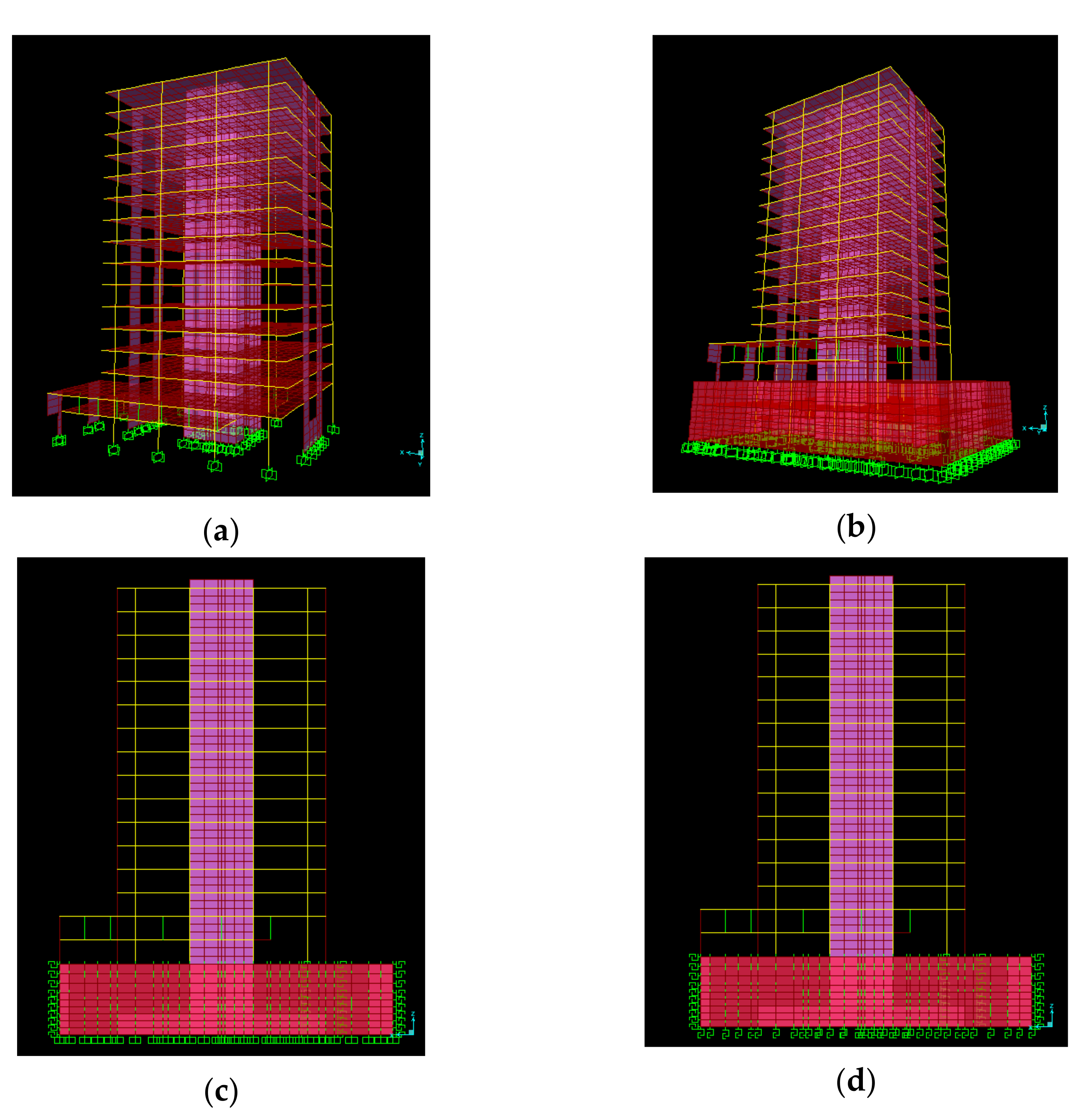
For comparison purposes, the foundation modeling options were:
  • Embedded on the first floor, see Figure 2a;
  • Embedded at the lowest underground level, see Figure 2b;
  • Embedded at the lowest underground level, with horizontal ballast, see Figure 2c;
  • Foundation slab supported on vertical springs, with horizontal ballast, see Figure 2d.
Each model that incorporated the soil-structure interaction considered the soil through equivalent springs, with stiffness constants given according to the ballast coefficient. The springs used were considered in two ways: (1) only in compression behavior and (2) compression and tension behavior. The latter, although formally incorrect, allowed an evaluation of the simplification of the model (because it requires only a linear-elastic analysis). Linear–elastic springs were used for all models, and the only nonlinearity considered was the only compression behavior already described, trying to keep the model as simple as possible. As is described in the next section, the ground motion records used had very low intensities in terms of maximum accelerations, so the soil behavior is expected to remain in the linear-elastic range, making the assumptions of this paragraph suitable for analysis purposes.
The soil ballast coefficients were obtained from the soil mechanics report [39], considering Terzaghi’s [37] formulas (Equations (1) and (2)), and the foundation width and length values B = 33.6 m and L = 44.8 m, which yielded a vertical soil ballast coefficient kv = 12.43 kN/mm3.
Horizontal ballast coefficient kh, where necessary, was modeled in three ways: (1) as a constant horizontal ballast equivalent to one–half the value of the vertical ballast kv; (2) as a linear distribution of horizontal ballast applied in the center of the vertical sections of the perimeter walls (using the approach given by Equation (3)); and (3), calculated using the method proposed by Kuesel [40] and revised by Ortigosa and Musante [41], which depends on the maximum horizontal acceleration considered. However, given that the horizontal ballast for each model—using the maximum acceleration of each seismic event—did not vary substantially (variance < 0.00X%), the average horizontal ballast from the 11 seismic events analyzed was used for all the models where necessary. The characteristics of the models analyzed in this work are summarized in Table 1.

3.2. Soil Modeling

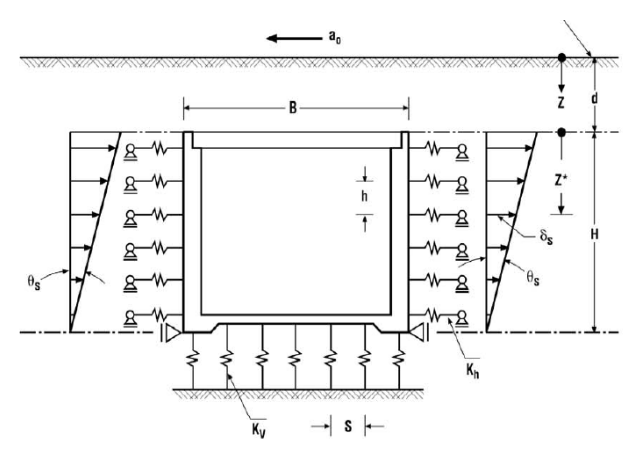
In this work, the SSI was modeled considering the method proposed by Kuesel by [40] and revised by Ortigosa & Musante [41]. This method models the SSI using a series of horizontal springs whose deformations are measured through iterative processes, where the maximum acceleration of the seismic event is the input variable. This method also has been applied to buried and semi–buried structures, such as pipelines, tunnels, or underpasses. The model is depicted in Figure 3. The iterative process for each soil layer i consists of the following steps:
  • Give an initial value to the ratio (K2i/K2,max), where K2i is the dimensionless shear modulus for seismic actions in layer i and K2,max is the maximum shear coefficient for small deformations from Table 2;
  • Use Equation (8) to calculate the dimensionless shear modulus of layer i;
  • Use Equation (6) to calculate the shear modulus of the soil in layer i, where σ ¯ v i is the effective vertical tension of soil in layer i;
  • Use Equations (5) and (7) to calculate the horizontal spring of layer i and the seismic shear deformation in the same layer θ s i , respectively. z i is the depth of layer i, measured from the ground surface level, a 0 is the maximum ground acceleration expressed as a fraction of the acceleration of gravity, γ is the unit weight of soil, H is the depth of the underground structure, Z i is the distance from the highest point of the underground structure to the soil layer i, and ν is the Poisson’s ratio of the soil;
  • Using Figure 4, input the seismic shear deformation to obtain the ratio (K2i/K2,max);
  • Compare the value given by step 1 (or the previous step) with the value obtained in step 5 using some convergence criteria (relative error, absolute error, etc.). If convergence is achieved, then use the obtained value for the associated horizontal spring coefficient of layer i. Otherwise, go back to step 2 with the new value of the ratio (K2/K2,max)i
θ s i = 1 0.0167 · z i · a g · γ · z i G c i
G c i = 53 · K 2 i · σ v i
K 2 i = K 2 i K 2 , m a x i · K 2 , m a x
k h i = 2 1 ν · G c i H · 1 1 Z i H 2 .
Table 1. Models analyzed in this study.
ModelEmbedded 1st FloorEmbedded FoundationVertical BallastConstant Horizontal BallastLinear Horizontal BallastKuesel Horizontal BallastBallast in Compression OnlyRockingCracking Factor
1Yes
2 Yes
3 Yes Yes
4 Yes Yes
5 Yes Yes Yes
6 Yes Yes Yes
7 Yes Yes YesYes
8 Yes Yes
9 Yes Yes Yes
10 Yes Yes Yes
11 Yes Yes YesYes
12 Yes Yes
13 Yes YesYes
14 Yes Yes Yes
15 Yes YesYesYes
16 Yes YesYes 0.50
17 Yes YesYes 0.29
18 Yes YesYes 0.21
19 Yes YesYes 0.50
20 Yes YesYes 0.29
21 Yes YesYes 0.21
22 Yes
23 Yes Yes
24 YesYes
25 YesYes Yes
26 Yes Yes
27 Yes YesYes
28 YesYes Yes
29 YesYes YesYes
30Yes 0.29
31 Yes 0.29
32 Yes 0.29
33 Yes Yes 0.29
34 Yes Yes 0.21
35 Yes YesYes0.50
36 Yes YesYes0.29
37 Yes Yes 0.21
38 Yes YesYes0.15
39Yes 0.70
40 Yes YesYes 0.70
41 Yes YesYesYes0.70
42 Yes Yes 0.70
43 Yes 0.70

3.3. Ground Motion Records

The records used as ground motion input for the time-history analyses were taken from the accelerometers located at the foundation slab. As the foundation–structure interaction was considered to be registered by the accelerometers, and the foundation slab was not included in the models embedded at the base level (level-3). As a result, models that included vertical springs could not be compared to site records.
From the 16 installed accelerometers, records from units 1, 2, 3, and 4 were used as input for the numerical models. The records from accelerometers 1 and 2 were used as inputs in the X and Y directions of the building, respectively. On the other hand, the average of the records from accelerometers 3 and 4 (vertical direction) was used as input in the Z–direction.
All the seismic records were subjected to the same centering and filtering procedure to minimize high and low–frequency noise errors before comparison and/or use as ground motion input. As a first step, each record was centered to zero for ordinate axes with a tolerance of 10−5 g, to then use a band–pass filter via Fourier analysis to reduce the low and high frequencies that distort the signal. Equation (9) was used for this last step, with Fmin = 0.25 Hz and Fmax = 25 Hz, typical values used in record filters.
H f = 1 1 + f 2     F m i n   · F m a x f · F m a x     F m i n 2 .
Rocking is the deformation of the foundation plane to the horizontal due to differential deformations of the soil or the foundation itself; while this factor is traditionally assumed to be very small, this work evaluated it in some models. Cases of rocking or rolling as the input used the average Z from vertical accelerometers 3 and 4, divided by the X and Y arms to the center of gravity (considering the foundation slab dimensions), to introduce rotation in the corresponding X and Y directions.
Each model was subjected to a linear dynamic modal analysis considering every seismic event. This used the first 120 modes, which included more than 90% of the translational mass of the building. All models were assumed to have damping of 5% of the critical damping.
For each analysis, inter-story shears and drifts were obtained and used as representative of the net internal forces and deformations for the comparison between the model results and the empirical measurements. Notwithstanding, models used to compare inter-story shears and drifts did not include cracking, rocking, or vertical ballast. This lattermost case made use of models, including horizontal ballast in the three forms presented in this work, as well as with or without soil–spring traction.
Table 2. Maximum shear coefficient for small deformations.
Soil Type Range   for   K 2 , m a x
Sand50–85
Gravel160–220
Fine soils and soils with cementation25·qu 1
1 qu is the unconfined compressive strength of soil from the test.

4. Results and Discussions

4.1. Selected Recordings

The final dataset of seismic events was selected to ensure a representative sample of hypocenter depths, epicentral distances, and magnitudes. Thus, from the 72 seismic events recorded by the monitoring system installed at the Alcazar Building, 11 were included, listed, and described in Table 3 (events 5, 12, 37, 47, 52, 55, 57, 62, 65, 71, and 72).
The installed accelerometer network recorded each seismic event at a 100 Hz sample rate, using a simple trigger, starting the recording when the acceleration exceeds 10% of the maximum in–rest acceleration, and ending the recording when the maximum acceleration is exceeded for the last time. The final selection of time windows for analysis purposes was made by visual observation criteria. Table 4 shows the time window duration of each recording used as input for the models, initially determined by software analysis.
Figure 5 shows an example of full on-site recording and the time window used for the analysis.
Table 3. Parameters of seismic events analyzed.
EventDate and Time
(CLT)
Magnitude
(Mw or Ml)
Mercalli Intensity in Viña del MarHypocenter Depth (km)Epicenter Distance from Viña del mar (km)Maximum Input Acceleration (g)
504/04/2010
23:32:12
USGS: 4.5 Mw
CSN: 4.8 Ml
USGS: III
CSN: IV
USGS: 58.6
CSN: 68.6
USGS: 57
CSN: 64
0.0067
Registered on Axis Y
1205/01/2010
10:41:08
USGS: 5.0 Mw
CSN: 5.3 Ml
USGS: III
CSN: III
USGS: 35.0
CSN: 35.3
USGS: 39
CSN: 74
0.0110
Registered on Axis X
3710/22/2010
23:38:14
USGS: 5.2 Mw
CSN: 5.4 Ml
USGS: II
CSN: II
USGS: 44.0
CSN: 44.0
USGS: 383
CSN: 383
0.0022
Registered on Axis Y
4701/02/2011
17:20:18
USGS: 7.1 Mw
CSN: 7.0 Mw
CSN: 6.9 Ml
USGS: I
CSN: I
USGS: 25.1
CSN: 17.8
USGS: 611
CSN: 628
0.0005
Registered on Axis Y
5201/21/2011
12:36:11
USGS: 5.0 Mw
CSN: 4.7 Ml
USGS: II
CSN: I
USGS: 18.2
CSN: 11.6
USGS: 108
CSN: 123
0.0010
Registered on Axis Y
5502/11/2011
17:05:31
USGS: 6.8 Mw
CSN: 6.8 Mw
CSN: 6.9 Ml
USGS: III
CSN: II
USGS: 28.0
CSN: 20.9
USGS: 405
CSN: 446
0.0017Registered on Axis X
5702/14/2011
00:40:10
USGS: 6.6 Mw
CSN: 6.3 Mw
CSN: 5.9 Ml
USGS: II
CSN: II
USGS: 25.4
CSN: 21.5
USGS: 288
CSN: 336
0.0006
Registered on Axis X
6202/27/2011
22:29:25
USGS: 5.8 Mw
CSN: 5.9 Mw
CSN: 5.9 Ml
USGS: II
CSN: I
USGS: 20.0
CSN: 31.5
USGS: 497
CSN: 519
0.0004
Registered on Axis Y
6503/17/2011
08:14:24
USGS: 5.1 Mw
CSN: 5.0 Ml
USGS: IV
CSN: IV
USGS: 19.2
CSN: 13.4
USGS: 57
CSN: 50
0.0113
Registered on Axis Y
7104/18/2011
21:57:29
USGS: 5.2 Mw
CSN: 5.0 Ml
USGS: IV
CSN: III
USGS: 20.7
CSN: 45.2
USGS: 59
CSN: 93
0.0034
Registered on Axis X
7204/19/2011
02:50:44
USGS: 5.3 Mw
CSN: 5.0 Ml
USGS: III
CSN: I
USGS: 10.2
CSN: 30.7
USGS: 104
CSN: 129
0.0041
Registered on Axis Y
USGS: United States Geological Survey [42]; CSN: Centro Sismológico Nacional (National Seismological Center, part of the College of Physical and Mathematical Sciences at the University of Chile) [43].
Figure 5. On-site seismic recording at the foundation of the building and time window.
Applsci 11 03190 g005
Table 4. Time window duration for each analyzed event.
Event #Total Record Time (s)Zero Time (s)Time Window (s)
5231.9927.056.00
12248.9927.056.00
37264.9920.0112.01
47383.9929.0168.02
52320.9945.956.00
55406.9931.0112.01
57344.995.0112.01
62258.990.056.00
65322.9911.056.00
71278.9911.556.00
72295.9912.056.00

4.2. Numerical Models vs. Recorded Measurements Comparisons

This section compares data recorded by on-site accelerometers with results obtained from each proposed model. The first comparison tested a well-established hypothesis in engineering practice that is embedding the building at a level no longer confined by soil, which assumes underground floors to be rigid and not to affect the behavior of the rest of the structure. To this end, the on-site record at the foundation of the building (level-3) was compared with that of the ground floor (level 1). Next, on-site records were compared with models by relative and absolute errors of different parameters. Models in which these values are lower implies more effective simulations of soil-structure interaction. Finally, story shears for each seismic instance were compared to determine variation and influence among different models.

4.2.1. Comparison between the Foundation and First–Floor Accelerations

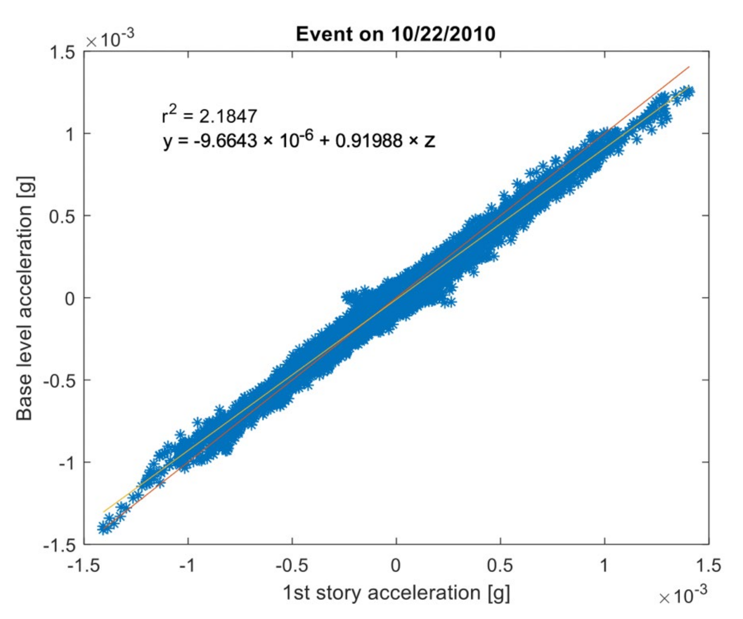
Accelerations in each direction were compared between the first floor and foundation slab for each event in the data set. Accelerometers 1 (foundation) and 5 (ground floor) were used for the X-direction; 2 (foundation) and 6 and 7 (average, ground floor), for the Y. Figure 6 shows this comparison in a plot where the position of the blue dots graph the foundation vs. first-floor accelerations. The red line is a linear regression as determined by the equation in the upper left corner. The yellow line, 45°, corresponds to perfect data coincidence.
For most of the analyzed events, although there is a slight similarity in point-to-point accelerations between the foundation and first-floor data, the graphed slope varies by more than 10%. A slope of 1 would imply that both records were the same, and therefore, the response of the entire underground structure can be assumed to be similar to that of a rigid body. These results suggest that the first level and the foundation do not move exactly in the same way: indeed, the slopes indicate that accelerations are at least 10% higher, on average, for the first floor than in the foundation, as it can be observed in Figure 6.

4.2.2. Comparisons Using Statistical Parameters

Among the several alternatives to compare time-history records (i.e., representative parameters of the entire record or averaged difference following point-by-point), this study used error formulas to compare on-site values with those of the models used in this work. Specifically, comparisons used absolute error of the analyzed recording window across representative parameters: maximum acceleration, number of crossover distortions, dominant frequency, and duration of the strongest signal, as detailed below.
In total, 46 models were run for the 11 events. The parameters used for the analysis were: the average absolute error, calculated using Equation (10); the relative error of the maximum acceleration calculated by Equation (11); the relative error of the number of crossover distortions, given by Equation (12); the relative error of the number of crossover distortions for the strongest signal of the recording, given by Equation (13); the relative error of the duration of the strongest signal, calculated through Equation (14); and the relative error of the dominant frequency, given by Equation (15). The definitions of the parameters and the formulas are listed below.
  • The average relative error is used to analyze the differences between the on-site records and the model results in a point-by-point approach. The average relative error for the accelerations of the event j, in the accelerometer k for the model m is calculated as:
    R E r e g j , k , m = i = 1 n j a m o d i , j , k , m a s i t i , j , k a s i t i , j , k n j
  • Maximum acceleration relative error compares the peak acceleration, essential to design, across different models for the same record or different records for the same model. In this study, the relative error across models is analyzed.
    R E a m a x j , k , m = a m a x m o d j , k , m a m a x s i t j , k a m a x s i t j , k · 100
  • The number of crossover distortions can be used to define whether two datasets are synchronized or not. In this case, the relative error of the number of crossover distortions is calculated using:
    R E c r o s s j , k , m = N c r o s s m o d j , k , m N c r o s s s i t j , k N c r o s s s i t j , k · 100
  • The comparison of the number of crossover distortions during the strongest part of the signal shows the significant changes between datasets. A lower number of this parameter comparing the times the strongest signal crossed the x-axis implies a better fit. This parameter is also useful, as it disregards small loads that may alter the data (wind, environmental vibrations). The relative error number of crossover distortions during the strongest part of the signal is calculated using:
    R E c r o s s S P j , k , m = N c r o s s S P m o d j , k , m N c r o s s S P s i t j , k N c r o s s S P s i t j , k · 100
  • The relative error for the duration of the strongest signal of the event is also used. The duration of the empirical window (10% maximum acceleration before and after peak) and that of the model are compared to each other to observe if the latter may reproduce the same window.
    R E D S P j , k , m = D S P m o d j , k , m D S P s i t j , k D S P s i t j , k · 100
  • The similarity in the dominant frequency between the model response and the recorded data would imply that the mechanical properties of the model closely match reality. The dominant frequency of the recording is obtained by Fourier transform followed by obtaining the maximum value of the real parts of the data. Then, the relative error of the dominant frequency of the recording is calculated:
    R E D F j , k , m = D F m o d j , k , m D F s i t j , k D F s i t j , k · 100
Only the predominant period of the records is analyzed (related to the first vibration mode), considering that the contribution of the higher modes in the dynamic response of the structure is negligible in the linear-elastic range.
In an effort to summarize the great amount of data available after the analyses performed and given the great dispersion of the data among sensors and seismic events considered, the median relative error among the 12 sensors were selected as representative of the performance of a combination model/event. Then, boxplots are created for every model and presented in the next section.

4.2.3. Analysis of Relative Errors

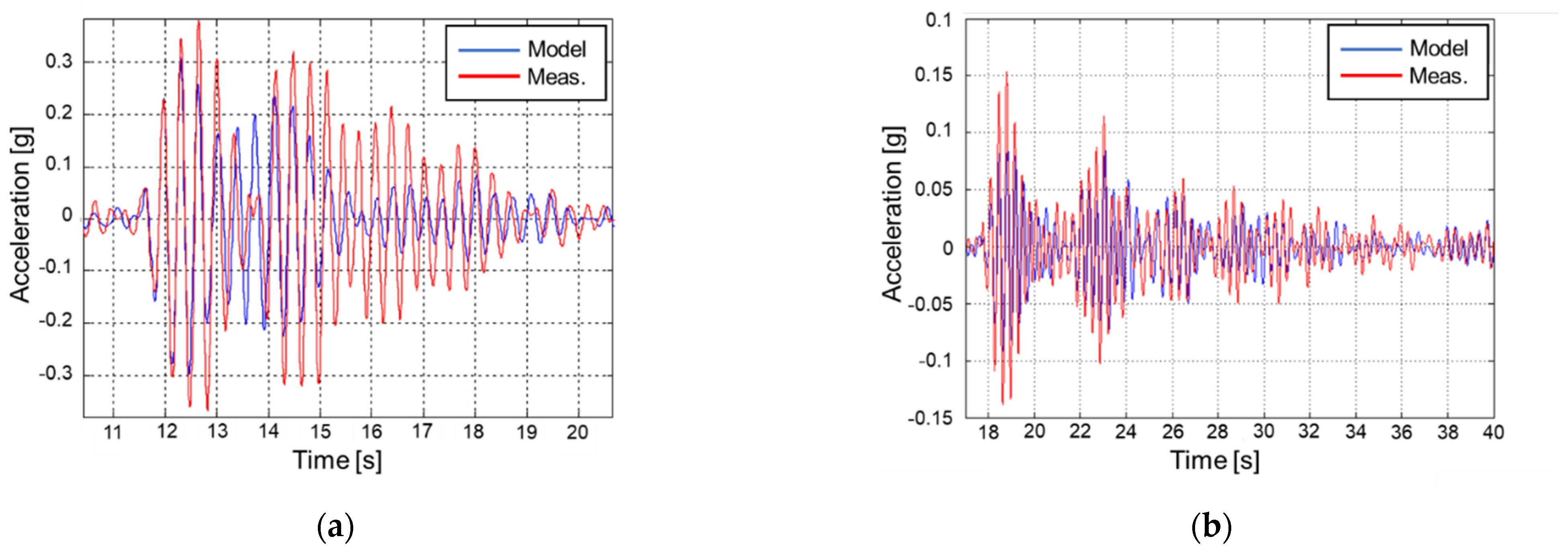
The average relative error among most models showed differences greater than 10% with empirical data. Thus, no model was able to completely represent the shape of the record, as observed in Figure 7a,b, where there is a clear difference between the model results and the actual behavior. Despite the above, the models with the lowest error were those where the vertical ballast is considered at the foundation instead of the embedded foundation, as can be observed in Figure 8.
The highest relative error for the maximum acceleration was given by the models that included cracking of the vertical elements (models 16 to 21), but there was no defined trend on the relative error for maximum accelerations among models. This parameter, across accelerometers and models, was relatively high, exceeding by 10% in almost every analysis. In Figure 9, the median relative errors on the maximum acceleration for all the models and sensors analyzed are depicted. In this case, it can be observed that the models that considered vertical springs at the base of the structure usually have greater differences with the measured data. From the models without vertical springs at the base, those with a better fit with the measured data are models 2, 4, 5, 12 and 13. All of those models consider the underground stories, and most of them consider the soil-structure interaction using horizontal springs. It should be observed that the relative error of model 1 (embedded at the base of the first story) is on the order of magnitude of the more complex models, but the accuracy is strongly dependent on the stiffness reduction factor (in this case, as the ground motions were not very strong, to not consider a reduction factor leads to better results).
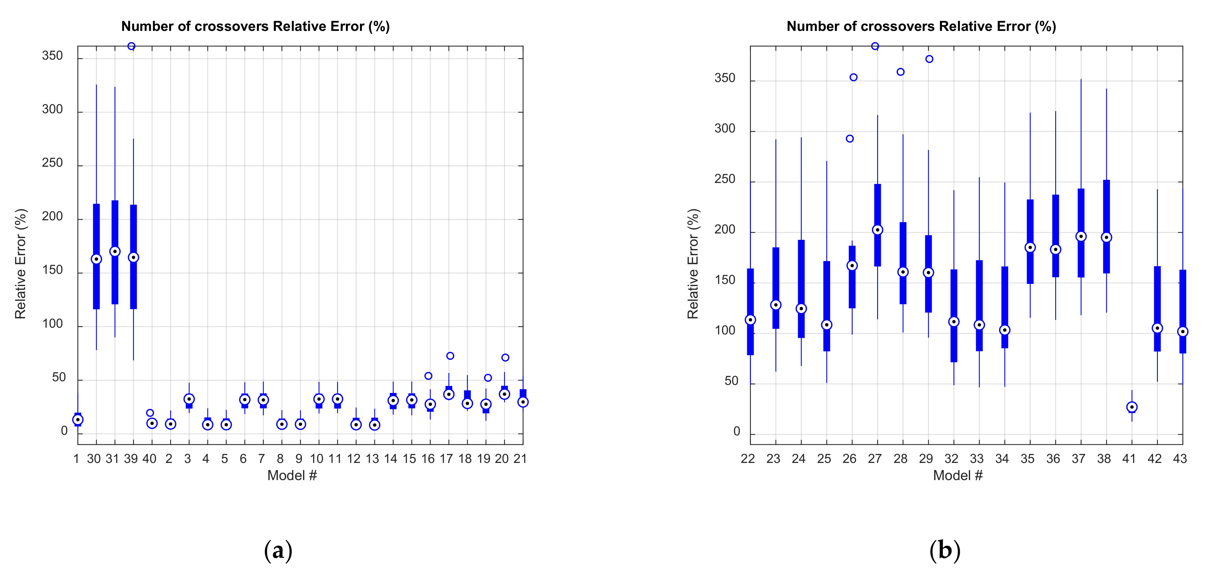
The relative error of the number of crossover distortions was usually greater in models where vertical springs were included at the base level, except for model 41 (Figure 10). In this case, the behavior is similar to that of the maximum acceleration: the models embedded at the base level with horizontal springs are the ones with best-fit to the actual behavior of the structure.
From the models without vertical springs at the base, those that included rocking or rolling vertical inputs (models 3, 6, 7, 10, 11, 14, and 15) presented larger percentages of relative error compared to those that consider the vertical input as the average of the records of accelerometers 3 and 4 (models 1, 2, 4, 5, 8, 9, 12, 13 and 40). This parameter had the same trend as the number of crossover distortions in the whole record and for the strongest signal.
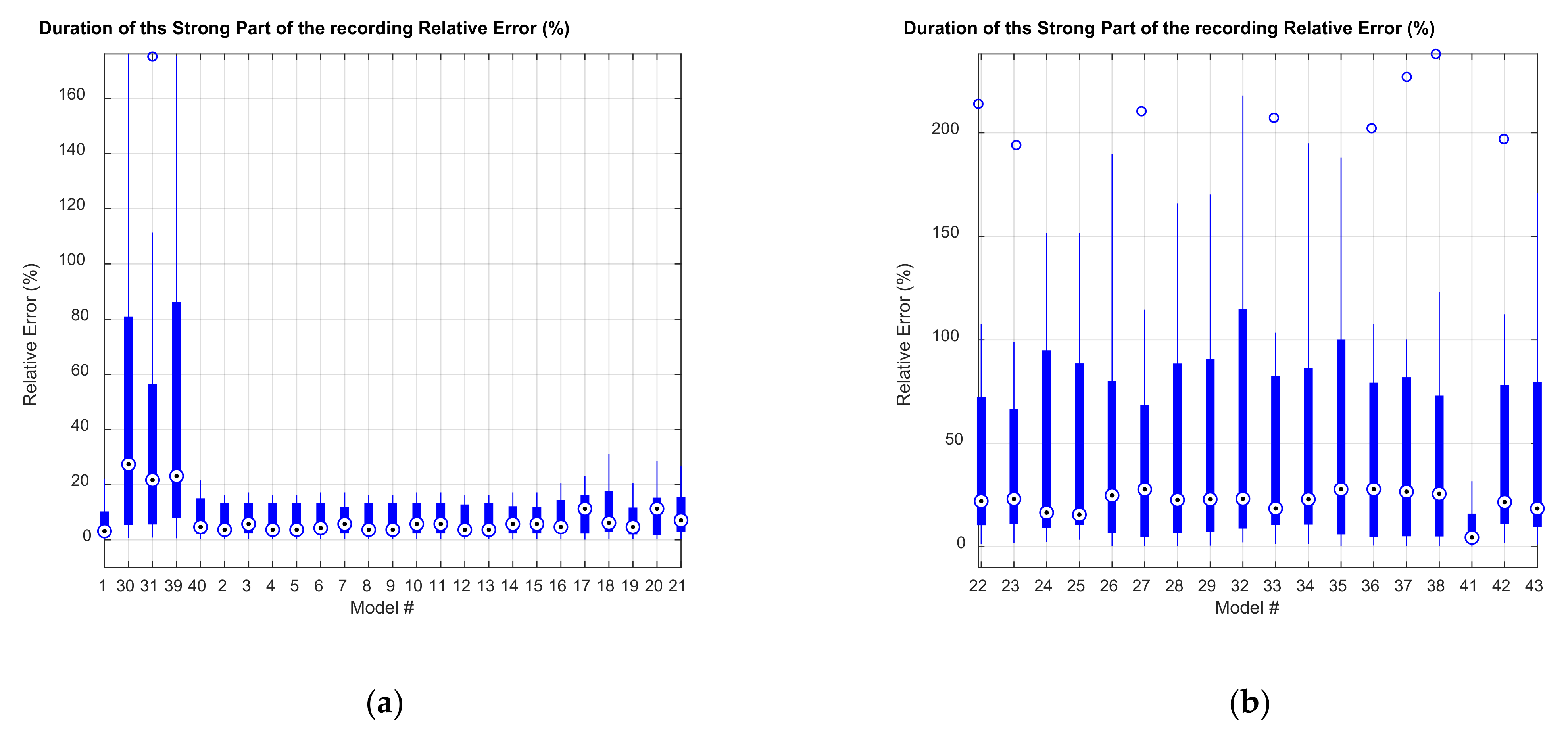
The relative error of the duration of the seismic event is greater for models where vertical elements were considered with a cracking factor less than 0.7. In general, the relative errors of the duration for the strongest signal are small. Among cases that do exceed 20%, the lowest relative errors are generally from models that do not consider rocking as an input (models 1, 2, 4, 5, 8, 9, 12, 13, and 40). Again, the models that consider vertical springs had a less accurate performance than models embedded at the base, as observed in Figure 11.
The relative error of the dominant frequency of the recording is greater for models where vertical elements were considered with a cracking factor less than 0.7, except for the event 62. In general, the models without cracking or with cracking factor 0.7 (models 1 to 15 and 40) and without rocking (models 1, 2, 4, 5, 8, 9, 12, 13, and 40) show lower relative errors concerning the dominant frequency of the recording. This holds except for the event on 27 February 2011, which presented an error of 241.67% compared to accelerometers in the X-direction. Less dispersion can be observed in Figure 12 concerning the other parameters analyzed, which is attributed to the number of frequencies analyzed (100), which reduces the possibilities of dispersion. The models with a best-fit are still the ones embedded at the base and that consider the lateral interaction with the soil using horizontal springs.
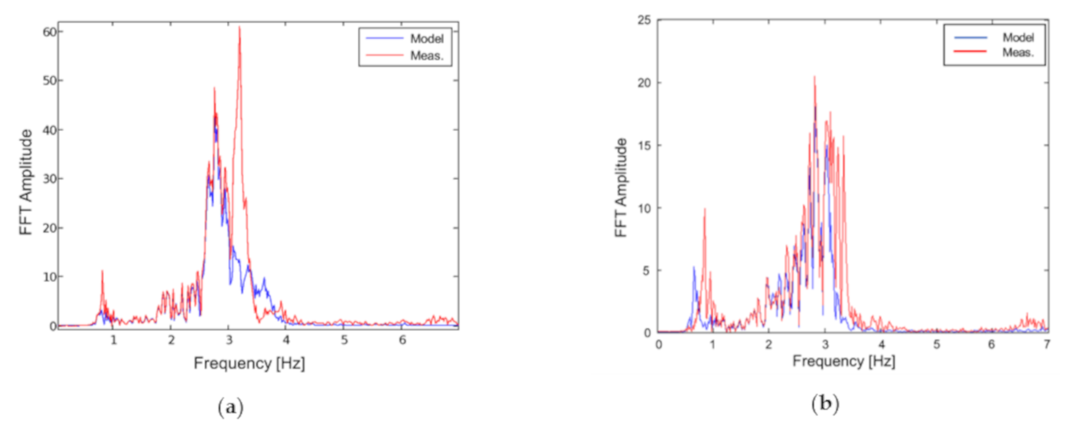
Models 12 and 14 were shown to have the best fit to empirical data and were selected for Figure 7 and Figure 13. Plots in Figure 7 and Figure 13 show two seismic events with the highest acceleration peak comparing accelerometer 14, both on-site and modeled. Model 12 corresponds to a model embedded at the foundation level, with Kuesel horizontal ballast and considering traction–only springs. Model 40 considers the structure embedded in the foundation level, with Kuesel horizontal ballast, without traction and a cracking factor of 0.7 for vertical elements.

4.2.4. Comparison of Inter-Story Drifts and Shears

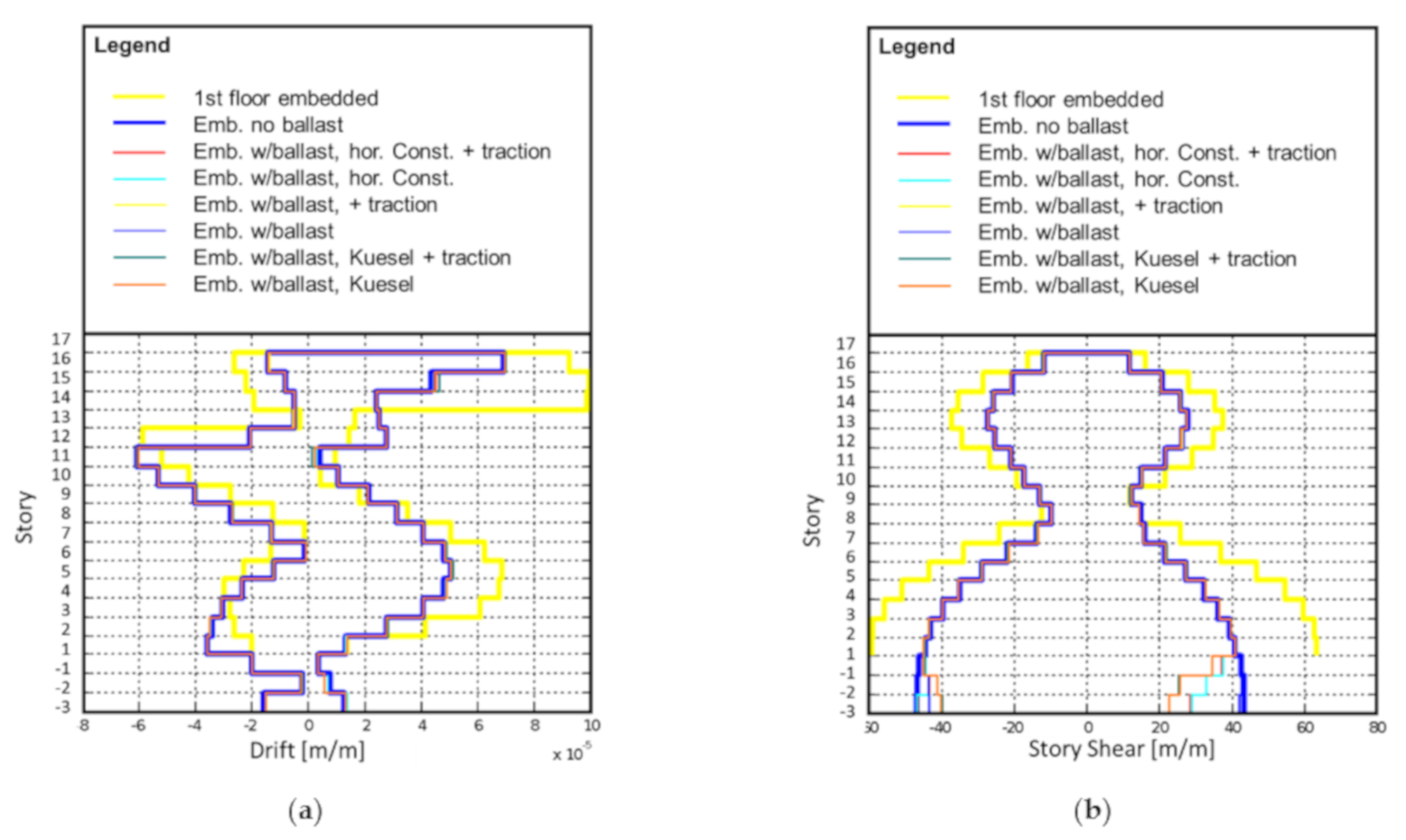
Inter-story drifts and shears are plotted in Figure 14a,b respectively, for models 1, 2, 5, 6, 8, 9, 12, and 13. Results were similar for all the considered seismic events modeled as embedded in the foundation, regardless of the considerations of the horizontal ballast, with or without traction springs. The first-floor embedded model, however, has appreciable differences concerning the others. Although of its similar shape, it gives overestimated values for all instances. For events with a maximum acceleration lower than 0.05 m/s2, inter-story drifts were greater in the underground levels with horizontal ballast models. Therefore, the soil-structure interaction should not be discarded even for small seismic events. For events with a maximum acceleration greater than 0.05 m/s2, ignoring horizontal ballast yields conservative results.
In terms of inter-story shear forces, results were similar for all the seismic events modeled as embedded in the foundation, regardless of horizontal ballast consideration, with or without traction springs. The first-floor embedded model, however, has appreciable differences from the others, giving overestimated values, just like the behavior observed in terms of inter-story drifts. The foundation-embedded model without ballast is mostly conservative in terms of inter-story shear forces for the upper stories, except for events 37, 47, 52, 55, 57, and 62; if the shear forces of the underground stories are considered, the model is conservative only for events 71 and 72.

5. Discussion and Conclusions

The huge relative errors obtained for models considering vertical springs at the base of the foundation can be attributed to a poor calibration of the spring constant used. This parameter was obtained from the soil mechanics report and is primarily intended to design the slab using a pseudo–static approach, and therefore, the actual value may be very different. The complex process that is required to validate and accurately define this parameter, and the high sensitivity that the numerical analyses performed shown to this parameter, make it unsuitable for design purposes to model the structure using vertical springs, at least until further studies regarding the calibration of the spring constant makes easier to define it. Furthermore, although there are no explicit requirements for the consideration of SSI in the modeling of structures, some suggestions can be found in the PEER Guidelines for Performance–Based Design [44] and the ASCE/SEI 7–16 (Section 12.13) [1], mainly proposing the use of horizontal and vertical springs and dashpots, similar to the approach used in this study. However, neither of both codes provides explicit equations for calculating the springs and dashpots constants, whose values were shown to be very critical for the accuracy of the analyses.
Larger relative errors were obtained for models with a cracking factor under 0.7, which suggests that the building behavior was slightly cracked for the low-intensity earthquakes studied. This confirms the recommended 0.7 stiffness reduction factor applied to building elements during design (Los Angeles Tall Buildings Structural Design Council, [45]) to verify deformations of a medium-rise building.
For events with a maximum acceleration lower than 0.05 m/s2, inter-story drifts were greater in the underground levels with horizontal ballast models, demonstrating that the soil-structure interaction should not be discarded even for small seismic events.
Models without rocking best represented the structure response when embedded at the foundation level. This may be due to inputs from accelerometers located at level-3 in the foundation. The models that best-fit the on-site data were, based on relative error of crossover distortions, the relative error of duration for the strongest signal, and the relative error of the dominant frequency, the foundation-embedded model, with Kuesel horizontal ballast; and the foundation-embedded model, with Kuesel horizontal ballast, and a stiffness reduction factor of 0.7.
The Kuesel horizontal ballast model may model the soil using compression–traction springs. Indeed, the relative errors were shown to be similar for Kuesel with or without traction, as well as inter-story drifts and story shears, with no visible differences. This result is supported by [16], who reached a similar conclusion for a high-rise building. However, this conclusion is still to be tested for the response of the structure under strong motions.
Notwithstanding the results presented above, it is necessary to obtain more data from instrumentation across a wider variety of structures to continue to evaluate better design and modeling practices. Similarly, further analyses, including nonlinear time-history and high-intensity events, are needed to best regulate building design.
In sum, and for design purposes, the results allow for the recommendation to:
  • Apply a stiffness reduction factor of 0.7 to all elements in deformation verification models for average-height buildings, including subterranean elements;
  • Embed the structure in the foundation level and not in the street level;
  • Whenever possible, include horizontal springs with Kuesel’s model with traction for the analysis of the structure;
  • Select spring constants carefully, primarily if vertical springs are to be considered in the modeling of the structure.

Author Contributions

Conceptualization, E.S. and G.L.; methodology, E.S., G.L. and A.L.; numerical modeling, E.S.; validation, E.S., A.L. and M.G.; formal analysis, E.S.; data postprocessing, E.S. and M.G.; writing—original draft preparation, E.S. and A.L.; writing—review and editing, A.L. and M.G.; visualization, E.S., A.L. and M.G.; supervision, A.L. and G.L. All authors have read and agreed to the published version of the manuscript.

Funding

This research received no external funding.

Institutional Review Board Statement

Not applicable.

Informed Consent Statement

Not applicable.

Data Availability Statement

The data presented in this study are available on request from the corresponding author. The data are not publicly available due to intellectual property.

Acknowledgments

The authors of this paper gratefully acknowledge Patricio Bonelli for facilitating the building’s collected data and structural drawings.

Conflicts of Interest

The authors declare no conflict of interest.

References

  1. ASCE. Minimum Design Loads and Associated Criteria for Buildings and Other Structures; American Society of Civil Engineers: Reston, VA, USA, 2017; ISBN 9780784410851. [Google Scholar]
  2. INN. NCh433.Of1996 Mod.2009—Diseño Sísmico de Edificios (In Spanish); Instituto Nacional de Normalización: Santiago, Chile, 2009. [Google Scholar]
  3. NRCC. National Building Code of Canada; NRCC: Ottawa, ON, Canada, 2015. [Google Scholar]
  4. Karapetrou, S.T.; Fotopoulou, S.D.; Pitilakis, K.D. Seismic vulnerability assessment of high-rise non-ductile RC buildings considering soil-structure interaction effects. Soil Dyn. Earthq. Eng. 2015, 73, 42–57. [Google Scholar] [CrossRef]
  5. Kim, S.; Stewart, J.P. Kinematic soil-structure interaction from strong motion recordings. J. Geotech. Geoenviron. Eng. 2003, 129, 323–335. [Google Scholar] [CrossRef]
  6. Raychowdhury, P.; Hutchinson, T.C. Performance of seismically loaded shearwalls on nonlinear shallow foundations. Int. J. Numer. Anal. Methods Geomech. 2011, 35, 846–858. [Google Scholar] [CrossRef]
  7. NEHRP. Soil—Structure Interaction for Building Structures; National Institute of Standards and Technology: Gaithersburg, MD, USA, 2012.
  8. Torabi, H.; Rayhani, M.T. Three dimensional finite element modeling of seismic soil-structure interaction in soft soil. Comput. Geotech. 2014, 60, 9–19. [Google Scholar] [CrossRef]
  9. Hokmabadi, A.S.; Fatahi, B. Influence of foundation type on seismic performance of buildings considering soil-structure interaction. Int. J. Struct. Stab. Dyn. 2016, 16, 1–29. [Google Scholar] [CrossRef]
  10. Riaz, M.R.; Motoyama, H.; Hori, M. Review of soil-structure interaction based on continuum mechanics theory and use of high performance computing. Geosciences 2021, 11, 72. [Google Scholar] [CrossRef]
  11. Salciarini, D.; Frizza, M.; Tamagnini, C.; Arroyo, M.; Abadìas, D. Macroelement modeling of SSI effects on offshore wind turbines subject to large number of loading cycles. Procedia Eng. 2016, 158, 332–337. [Google Scholar] [CrossRef] [Green Version]
  12. Finn, W.D.L. A study of piles during earthquakes: Issues of design and analysis. Bull. Earthq. Eng. 2005, 3, 141–234. [Google Scholar] [CrossRef]
  13. Dutta, S.C.; Bhattacharya, K.; Roy, R. Response of low–rise buildings under seismic ground excitation incorporating soil-structure interaction. Soil Dyn. Earthq. Eng. 2004, 24, 893–914. [Google Scholar] [CrossRef]
  14. Dutta, S.C.; Roy, R. A critical review on idealization and modeling for interaction among soil-foundation-structure system. Comput. Struct. 2002, 80, 1579–1594. [Google Scholar] [CrossRef]
  15. Hayashi, Y.; Takahashi, I. soil-structure interaction effects on building response in recent earthquakes. In Proceedings of the 3rd UJNR Workshop on soil-structure Interaction, Menlo Park, CA, USA, 29–30 March 2004; pp. 1–8. [Google Scholar]
  16. Naeim, F.; Tileylioglu, S.; Alimoradi, A.; Stewart, J.P. Impact of foundation modeling on the accuracy of response analysis for a tall building. In Proceedings of the SMIP08: Seminar on Utilization of Strong–Motion Data, Los Angeles, CA, USA, 18 September 2008; pp. 19–56. [Google Scholar]
  17. El Ganainy, H.; El Naggar, M.H. Seismic performance of three–dimensional frame structures with underground stories. Soil Dyn. Earthq. Eng. 2009, 29, 1249–1261. [Google Scholar] [CrossRef]
  18. Tabatabaiefar, H.R.; Massumi, A. A simplified method to determine seismic responses of reinforced concrete moment resisting building frames under influence of soil-structure interaction. Soil Dyn. Earthq. Eng. 2010, 30, 1259–1267. [Google Scholar] [CrossRef]
  19. Saad, G.; Saddik, F.; Najjar, S. Impact of soil structure interaction on the seismic design of reinforced concrete buildings with underground stories. In Proceedings of the 15th World Conference on Earthquake Engineering, Lisbon, Portugal, 24–28 September 2012. [Google Scholar]
  20. Choinière, M.; Paultre, P.; Léger, P. Influence of soil-structure interaction on seismic demands in shear wall building gravity load frames. Eng. Struct. 2019, 198, 109259. [Google Scholar] [CrossRef]
  21. Sudarsana, I.K.; Widiarsa, I.B.R.; Predana, I.M.A. Analysis the effects of soil-structure interaction on the seismic behaviours of a 5–stories reinforced concrete building with basements. In Proceedings of the 3rd International Conference on Civil and Environmental Engineering (ICCEE 2019), Bali, Indonesia, 29–30 August 2019. [Google Scholar]
  22. Konstandakopoulou, F.D.; Evangelinos, K.I.; Nikolaou, I.E.; Papagiannopoulos, G.A.; Pnevmatikos, N.G. Seismic analysis of offshore platforms subjected to pulse–type ground motions compatible with European standards. Soil Dyn. Earthq. Eng. 2020, 129, 105713. [Google Scholar] [CrossRef]
  23. Konstandakopoulou, F.D.; Papagiannopoulos, G.A.; Pnevmatikos, N.G.; Hatzigeorgiou, G.D. Seismic hazard assessment of offshore platforms. J. Civ. Environ. Eng. 2019, 13, 272–276. [Google Scholar] [CrossRef]
  24. Luco, J.E.; Anderson, J.G.; Georgevich, M. soil-structure interaction effects on strong motion accelerograms recorded on instrument shelters. Earthq. Eng. Struct. Dyn. 1990, 19, 119–131. [Google Scholar] [CrossRef]
  25. Ghahari, S.F.; Abazarsa, F.; Avci, O.; Çelebi, M.; Taciroglu, E. Blind identification of the Millikan library from earthquake data considering soil-structure interaction. Struct. Control Health Monit. 2016, 23, 684–706. [Google Scholar] [CrossRef]
  26. Taciroglu, E.; Çelebi, M.; Ghahari, S.F.; Abazarsa, F. An investigation of soil-structure interaction effects observed at the MIT green building. Earthq. Spectra 2016, 32, 2425–2448. [Google Scholar] [CrossRef]
  27. Taciroglu, E.; Ghahari, S.F.; Abazarsa, F. Efficient model updating of a multi–story frame and its foundation stiffness from earthquake records using a timoshenko beam model. Soil Dyn. Earthq. Eng. 2017, 92, 25–35. [Google Scholar] [CrossRef]
  28. Shirzad-Ghaleroudkhani, N.; Mahsuli, M.; Ghahari, S.F.; Taciroglu, E. Bayesian identification of soil–foundation stiffness of building structures. Struct. Control Health Monit. 2018, 25, e2090. [Google Scholar] [CrossRef]
  29. Sotiriadis, D.; Klimis, N.; Margaris, B.; Sextos, A. Analytical expressions relating free-field and foundation ground motions in buildings with basement, considering soil-structure interaction. Eng. Struct. 2020, 216, 110757. [Google Scholar] [CrossRef]
  30. Stewart, J.P.; Fenves, G.L. System identification for evaluating soil-structure interaction effects in buildings from strong motion recordings. Earthq. Eng. Struct. Dyn. 1998, 27, 869–885. [Google Scholar] [CrossRef]
  31. Nascimbene, R. Numerical model of a reinforced concrete building: Earthquake analysis and experimental validation. Period. Polytech. Civ. Eng. 2015, 59, 521–530. [Google Scholar] [CrossRef] [Green Version]
  32. Bernuzzi, C.; di Gioia, A.; Gabbianelli, G.; Simoncelli, M. Pushover analyses of hand–loaded steel storage shelving racks. J. Earthq. Eng. 2017, 21, 1256–1282. [Google Scholar] [CrossRef] [Green Version]
  33. Lopez, A.; Dusicka, P. Implementation of a novel inertial mass system and comparison to existing mass–rig systems for shake table experiments. Appl. Sci. 2021, 11, 692. [Google Scholar] [CrossRef]
  34. CSI. ETABS 16: Structural Software for Building Analysis and Design; Computer & Structures Inc.: Walnut Creek, CA, USA, 2016. [Google Scholar]
  35. ACI. Building Code Requirements for Structural Concrete and Commentary (ACI 318–08); American Concrete Institute: Indianopolis, IN, USA, 2008. [Google Scholar]
  36. DIGITEXX. Accelerometers: D110-U; DIGITEXX: Carefree, AZ, USA, 2020. [Google Scholar]
  37. Terzaghi, K. Evaluation of coefficients of subgrade reaction. Géotechnique 1955, 5, 297–326. [Google Scholar] [CrossRef]
  38. Bonelli, P. Structural Drawings Alcántara Building 2008.
  39. Petersen, M. Soil Mechanics Report—Alcántara Building 2006.
  40. Kuesel, T.R. Earthquake design criteria for subways. J. Struct. Div. 1969, 95, 1213–1231. [Google Scholar] [CrossRef]
  41. Ortigosa, P.; Musante, H. Seismic earth pressures against structures with restrained displacements. In Proceedings of the 2nd International Conference on Recent Advances in Geotechnical Earthquake Engineering and Soil Dynamics, Santiago, Chile, 12 March 1991; pp. 621–628. [Google Scholar]
  42. USGS. United States Geological Survey. Available online: http://earthquake.usgs.gov/earthquakes/search/ (accessed on 19 April 2019).
  43. CSN. Centro Sismológico Nacional. Available online: http://www.sismologia.cl (accessed on 20 February 2018).
  44. PEER. Guidelines for Performance—Based Seismic Design of Tall Buildings; Pacific Earthquake Engineering Research Center: Berkeley, CA, USA, 2010. [Google Scholar]
  45. LATBSDC. An Alternative Procedure for Seismic Analysis and Design of Tall Buildings Located in the Los Angeles Region; Los Angeles Tall Building Structural Design Council: Los Angeles, CA, USA, 2020. [Google Scholar]
Figure 1. The case study building. (a) Northwest side of view; (b) accelerometers’ location; (c) Digitexx accelerometers model D-110U installed in the building.
Applsci 11 03190 g001
Figure 2. Model of the building: (a) embedded at the base of the first story; (b) embedded at the lowest underground level and without lateral ballast; (c) embedded at the lowest underground level with horizontal ballast; (d) using horizontal and vertical ballast in the soil-structure interface.
Applsci 11 03190 g002
Figure 3. Horizontal spring model for underground structures.
Applsci 11 03190 g003
Figure 4. Normalized seismic shear coefficient for granular soils.
Applsci 11 03190 g004
Figure 6. Seismic acceleration x-axis, foundation vs. first floor (10/22/2010).
Applsci 11 03190 g006
Figure 7. (a) Recorded on-site acceleration measurements and model accelerations on 16th story for model 12, excited by event 12, on sensor 14. (b) Recorded on-site acceleration measurements and model accelerations on 16th story for model 40, excited by event 72 on sensor 14.
Applsci 11 03190 g007
Figure 8. Median average relative errors for all the events analyzed. (a) Models without vertical springs at the base; (b) models with vertical springs at the base.
Applsci 11 03190 g008
Figure 9. Median relative errors on the maximum acceleration of the records. (a) Models without vertical springs at the base; (b) models with vertical springs at the base.
Applsci 11 03190 g009
Figure 10. Median relative errors on the number of crossover distortions. (a) Models without vertical springs at the base; (b) models with vertical springs at the base.
Applsci 11 03190 g010
Figure 11. Median relative errors on the duration of the strong part of the signal. (a) Models without vertical springs at the base; (b) models with vertical springs at the base.
Applsci 11 03190 g011
Figure 12. Median relative errors on the predominant frequency of the signal. (a) Models without vertical springs at the base; (b) models with vertical springs at the base.
Applsci 11 03190 g012
Figure 13. (a) Fourier transforms of on-site data and model 12, accelerometer 14, event 12. (b) Fourier transforms of on-site data and model 40, accelerometer 14, event 72.
Applsci 11 03190 g013
Figure 14. (a) Inter-story drifts in the Y-axis (event 12). (b) Inter-story shear forces in the Y-axis (event 12).
Applsci 11 03190 g014
Publisher’s Note: MDPI stays neutral with regard to jurisdictional claims in published maps and institutional affiliations.