
LDM-Ex-FDM: A Novel Multi-Service Transmission Scheme for the ATSC 3.0 System


Abstract
1. Introduction
- We propose a novel combined FDM/LDM multi-service transmission scheme, namely LDM-Ex-FDM, which is used to improve the reception performance of EL services without degrading the SNR threshold of CL services, thus enhancing the system coverage performance.
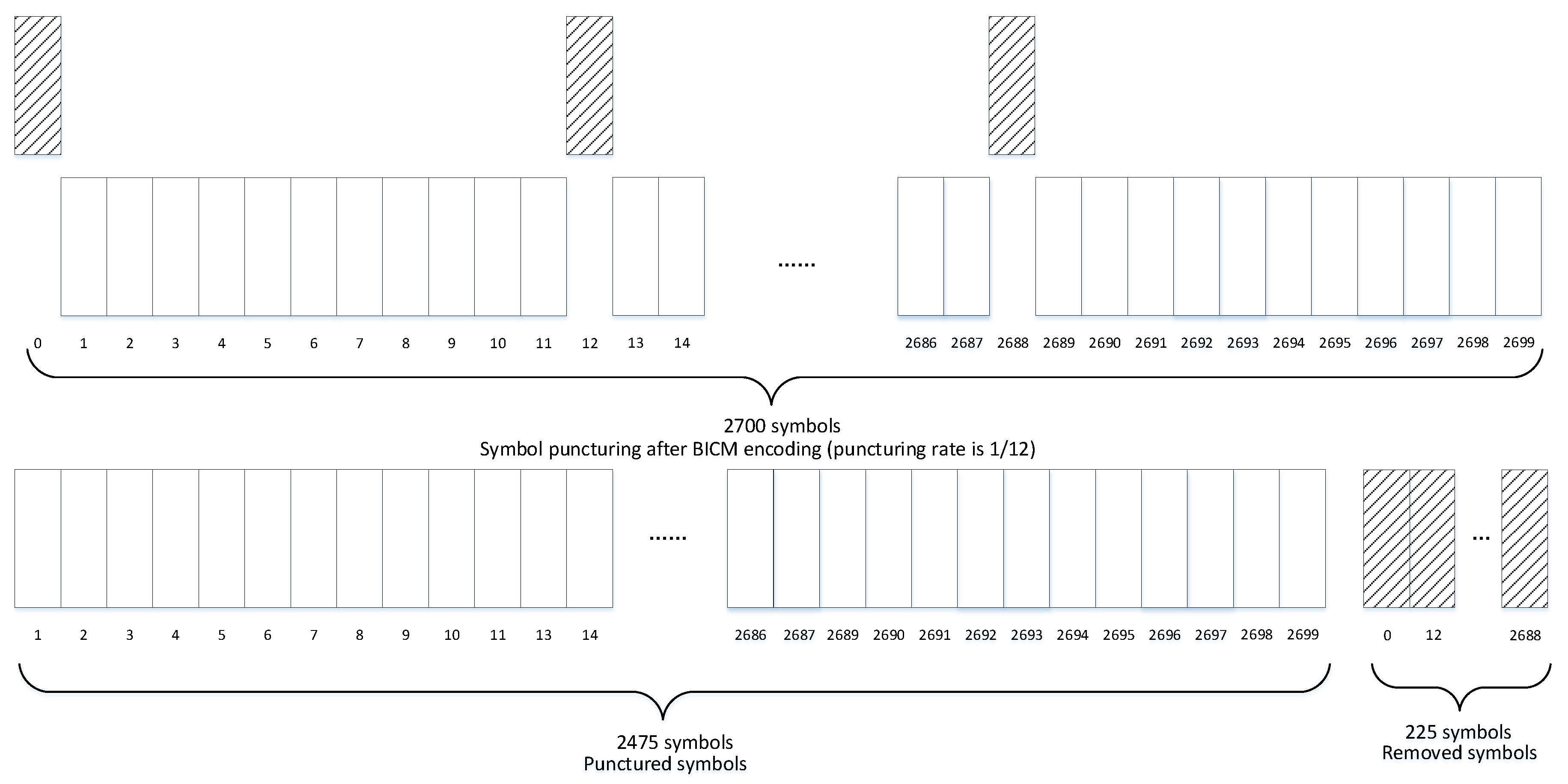
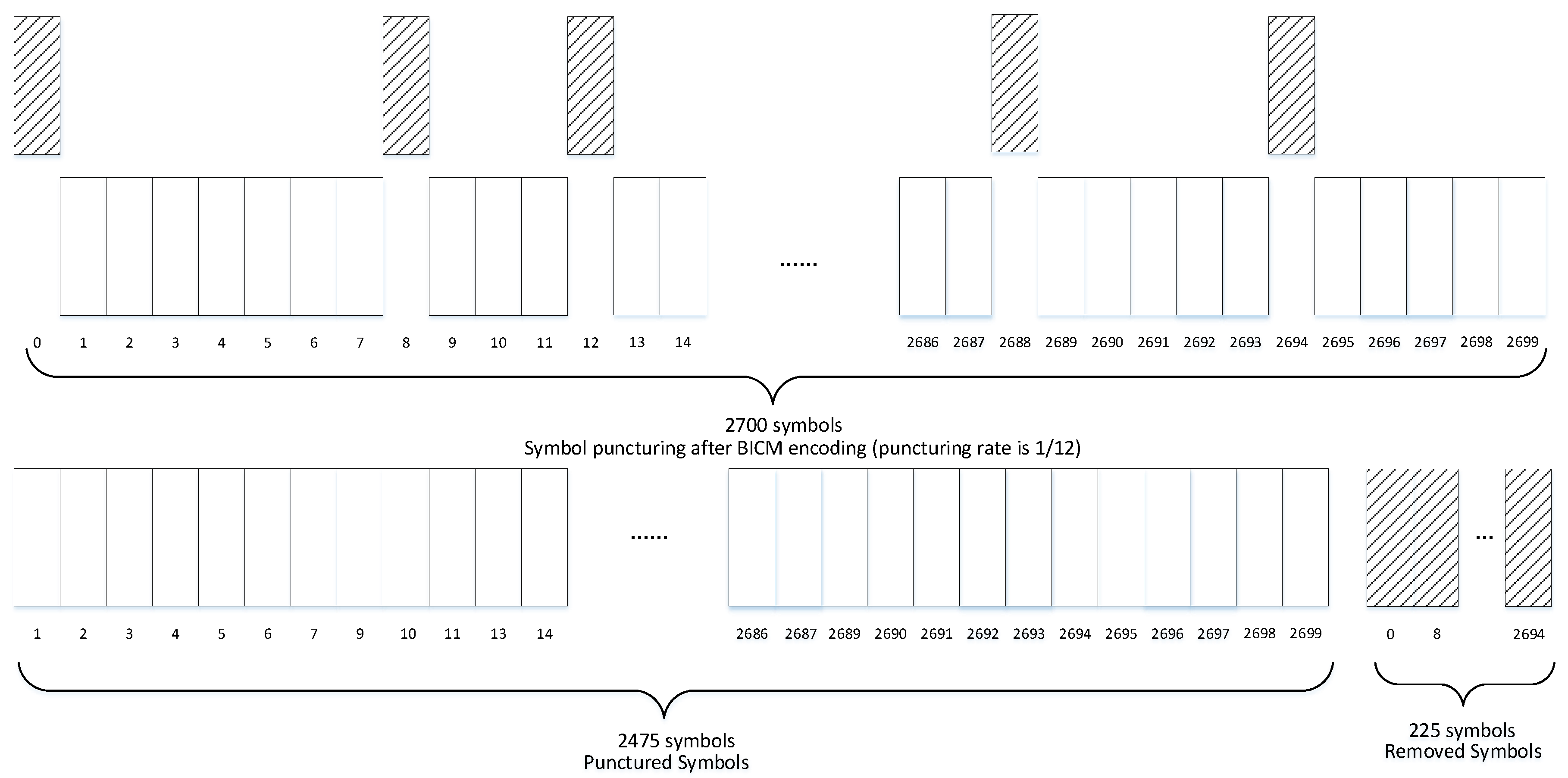
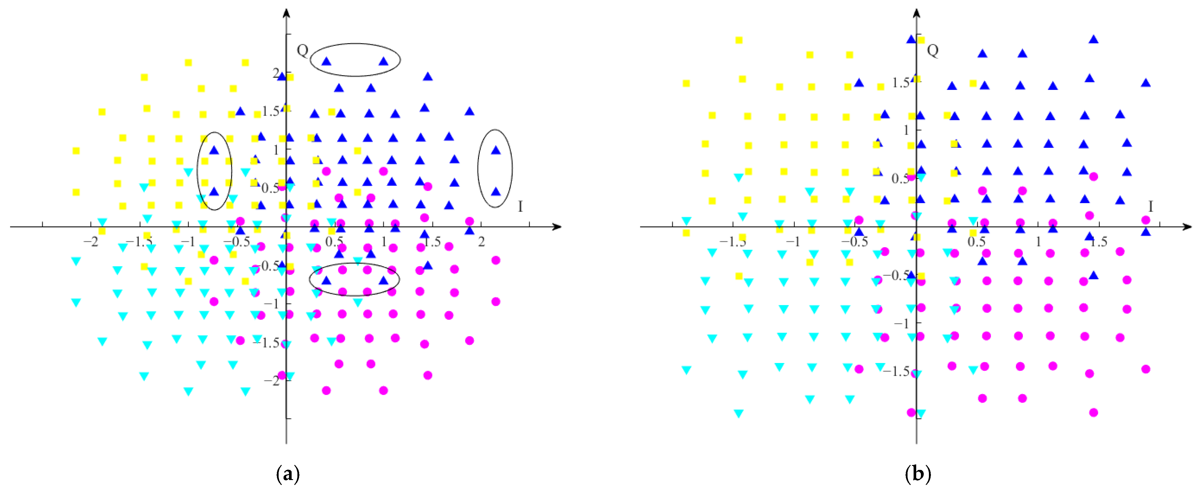
- Two BICM symbol puncturing strategies of the LDM-Ex-FDM scheme are proposed, i.e., equal interval symbol puncturing (EISP) and non-equal interval symbol puncturing (NEISP). The LDM-Ex-FDM scheme with EISP can be used for multi-service transmission under typical scenarios while the LDM-Ex-FDM scheme with NEISP performs better in multi-service transmission scenarios with low power injection levels, which will bring about the serious overlap of the constellation symbols of the LDM composite signal.
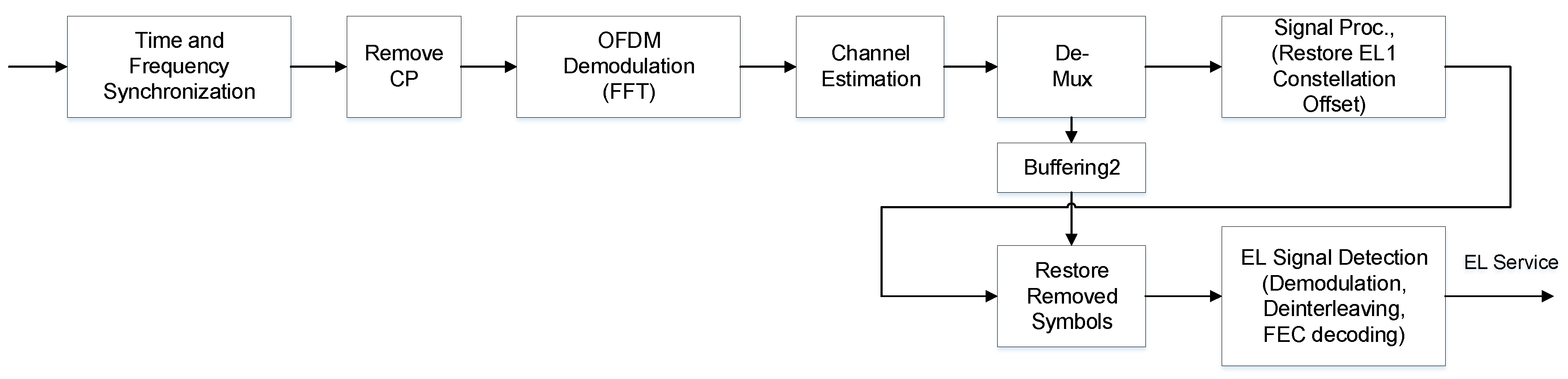
- At the receiving end, a DIC detector is also proposed to reduce the computational complexity and the signal processing delay. The effectiveness of the proposed detector is verified by simulation.
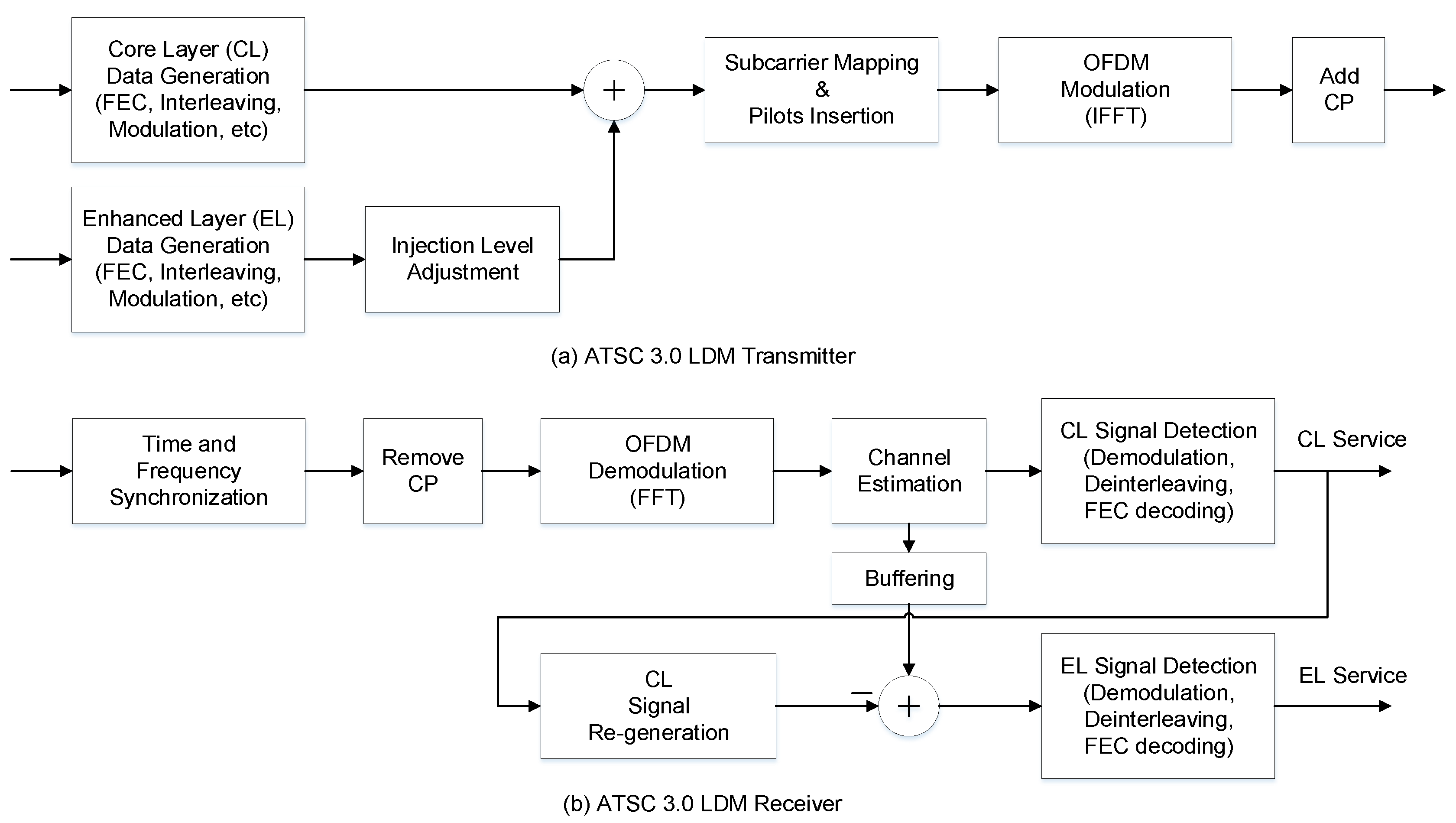
2. Advanced Television System Committee (ATSC) 3.0 System Overview
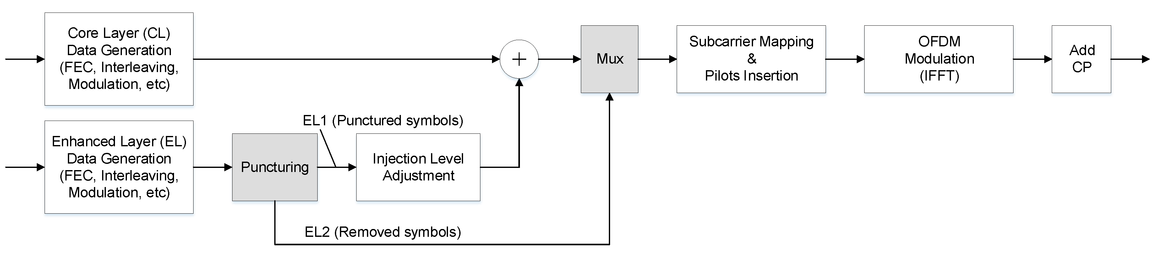
3. Layered Division Multiplexing Extension Frequency-Division Multiplexing (LDM-Ex-FDM) Scheme for the ATSC 3.0 System
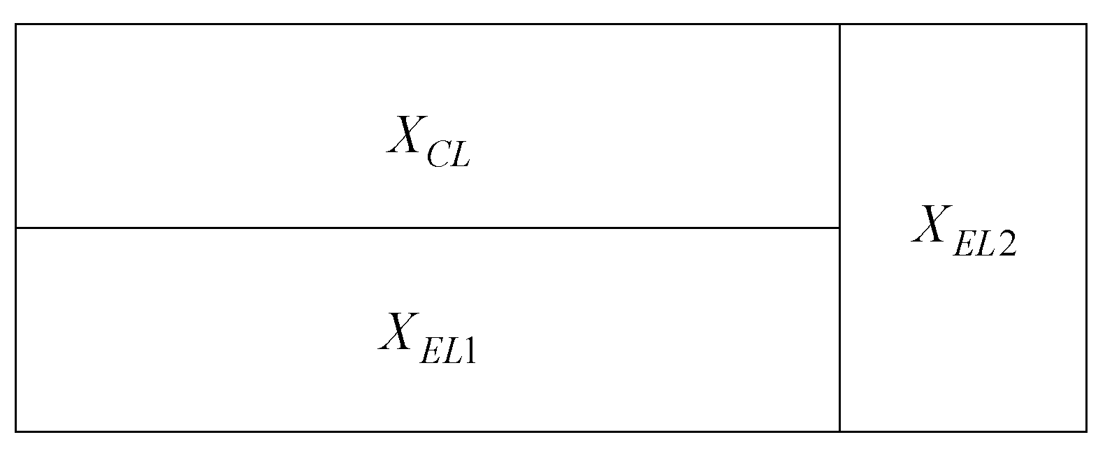
3.1. System Model
3.2. Puncturing Strategy
| Algorithm 1 Selection of Removed Symbols in NEISP Algorithm. |
| 1: Input: 2: r: puncturing rate of BICM symbols; x: BICM symbols for the fixed service 3: Output: 4: n: removed symbols EL2 5: Initialization: 6: determine the number Q of removed symbols; select the first Q symbols from x as the initial removed symbols 7: for k = Q + 1 to size(x) do • Step 1 (Symbols Power Calculation): calculate the power of each symbol in n and the power of the k-th symbol in x. • Step 2 (Removed Symbols Update): the symbol with the smallest power is discarded, the remaining Q symbols are used as newly removed symbols n, and then the positions of these removed symbols are marked. 8: end for |
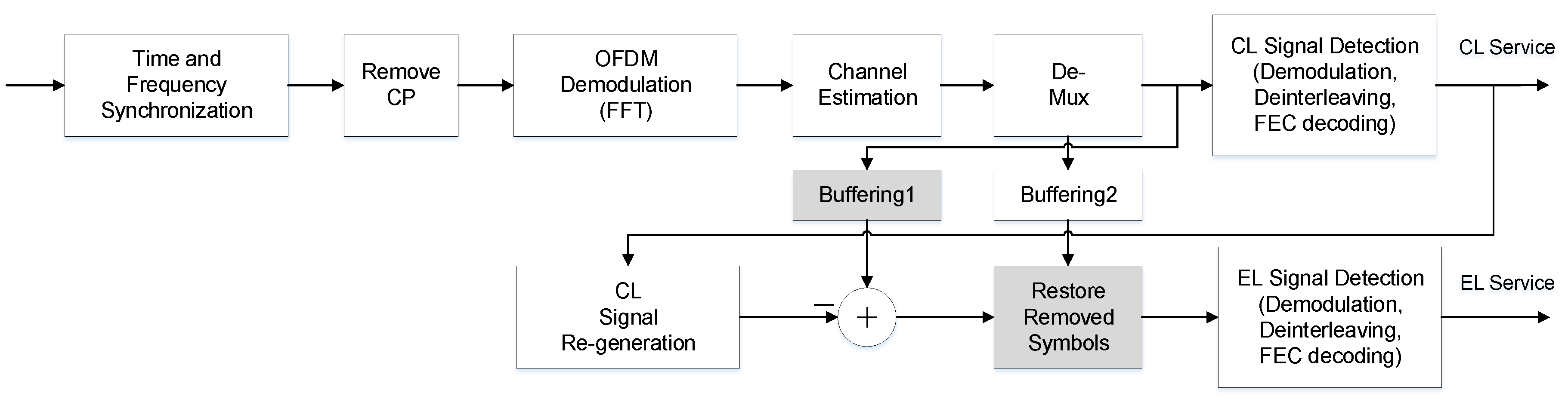
3.3. Direct-Interference-Cancellation Scheme
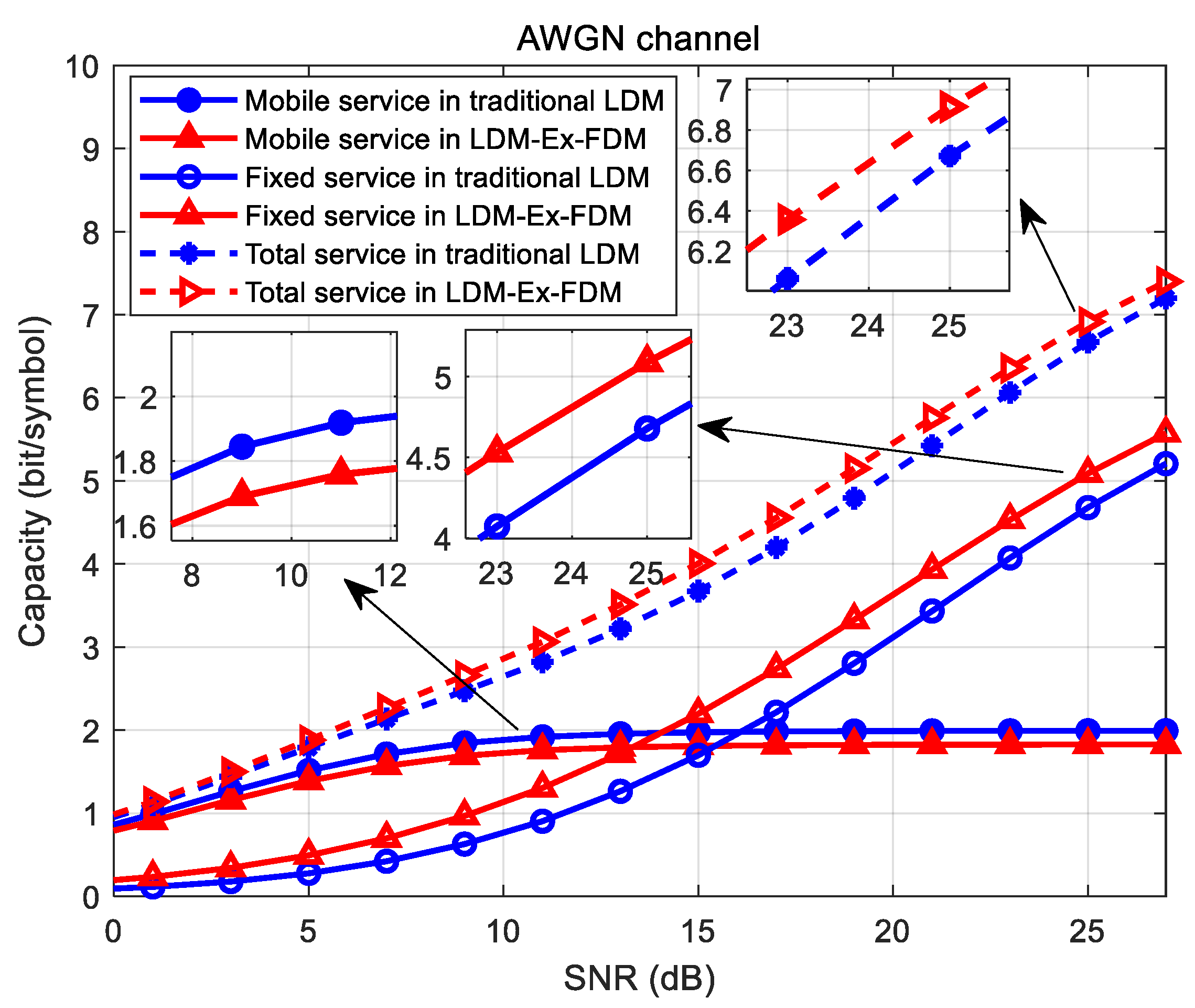
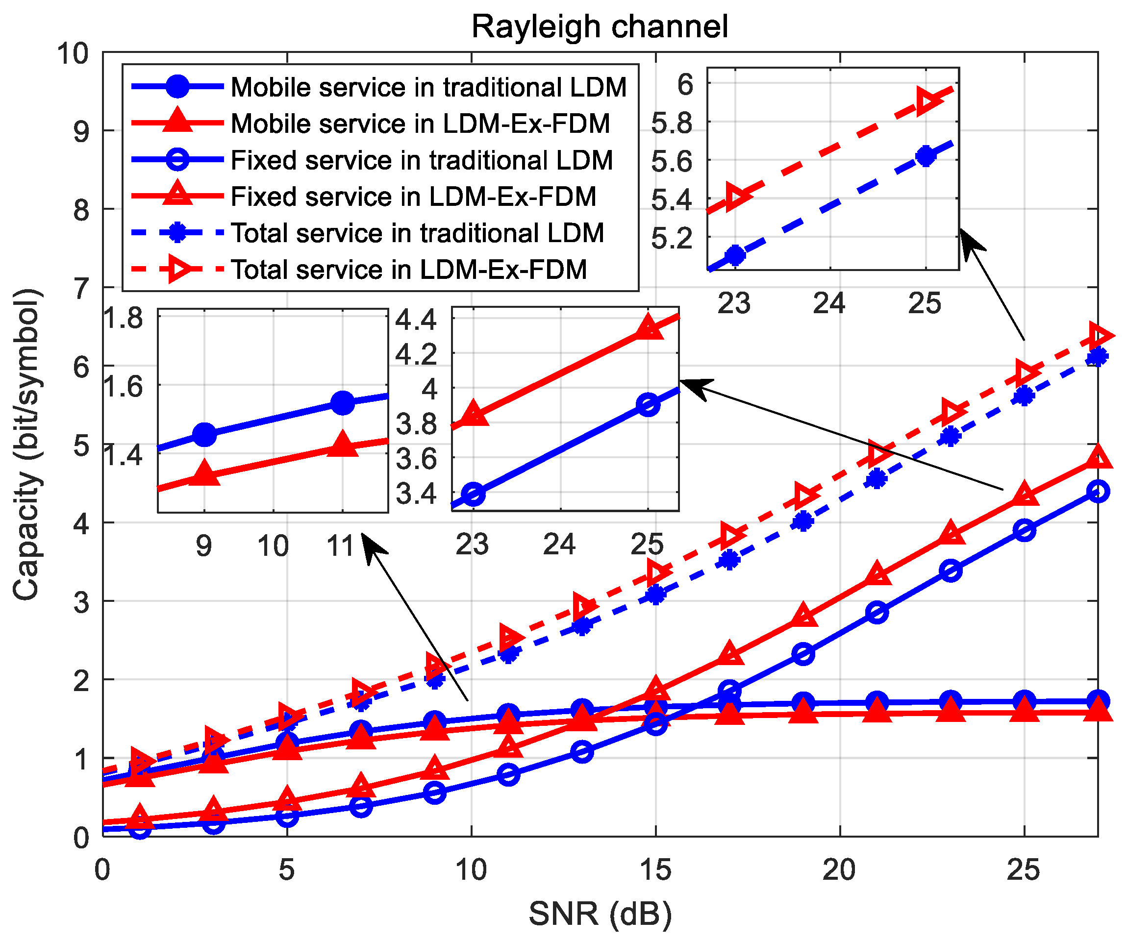
3.4. Bit-Interleaved Coded Modulation (BICM) Capacity Analysis
4. Simulation Results and Analysis
4.1. Simulation Setup and Parameters
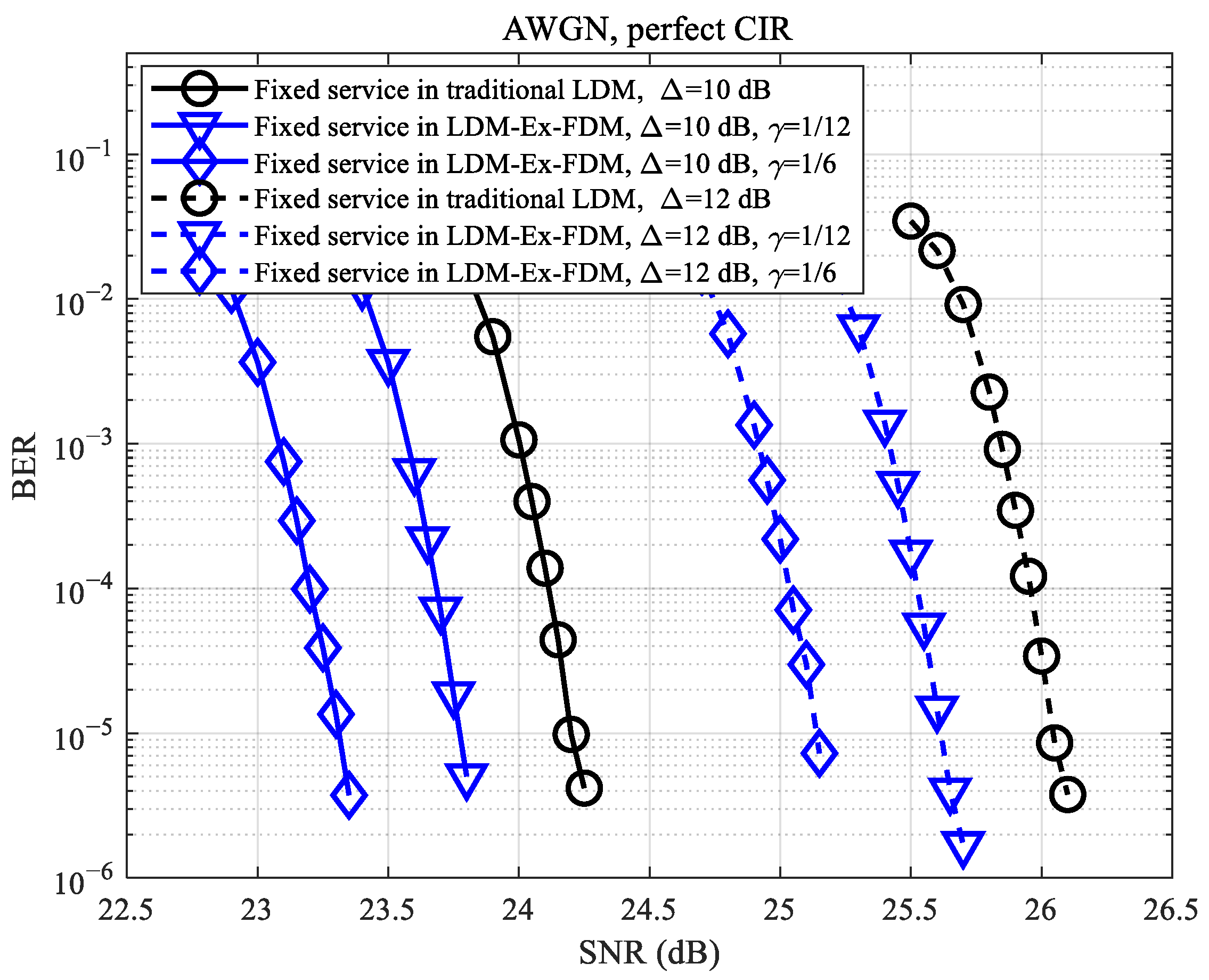
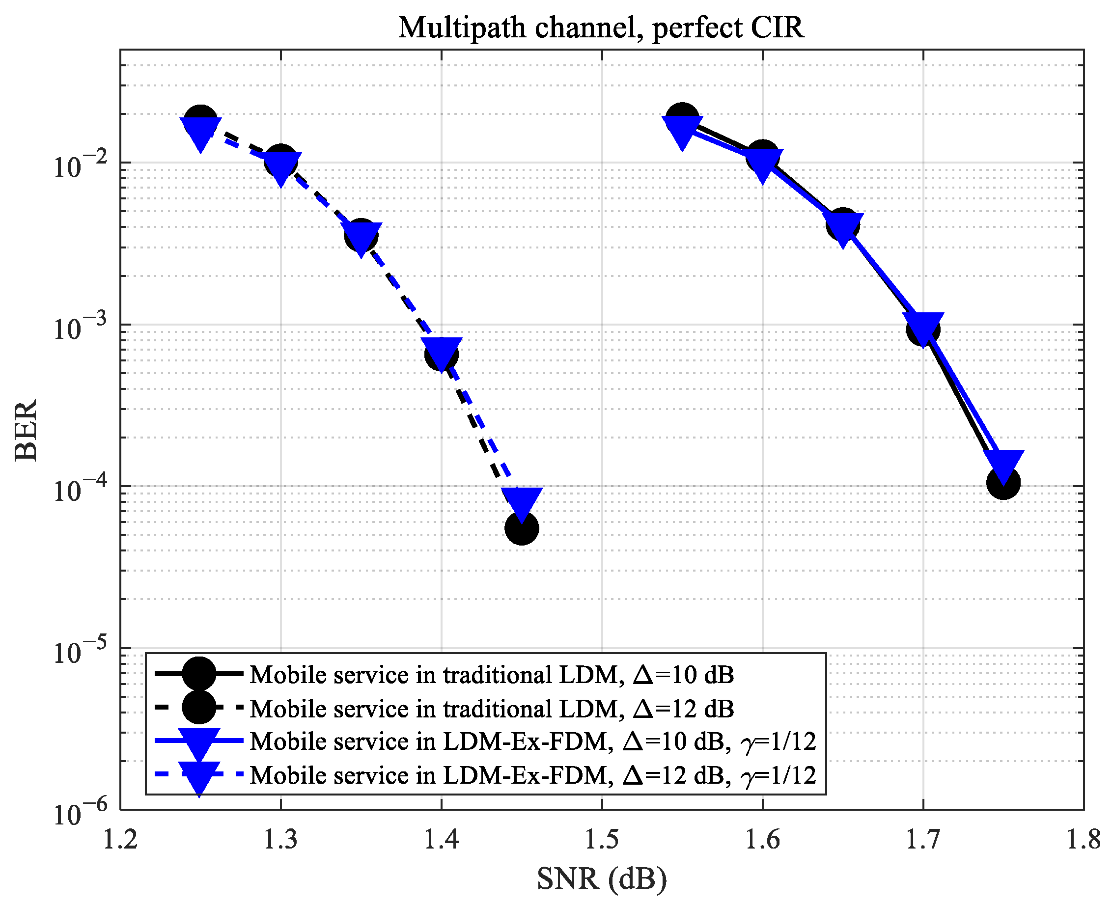
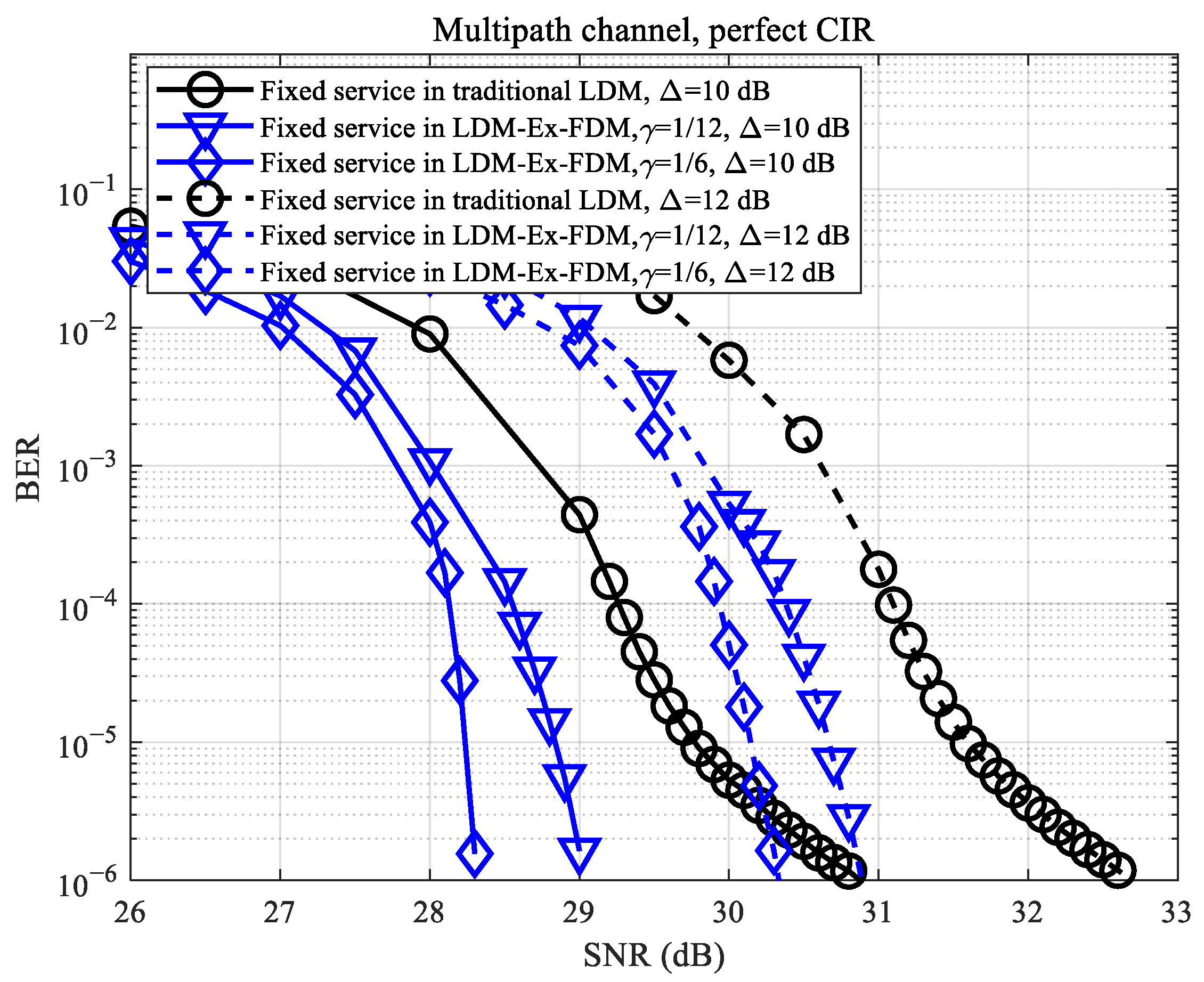
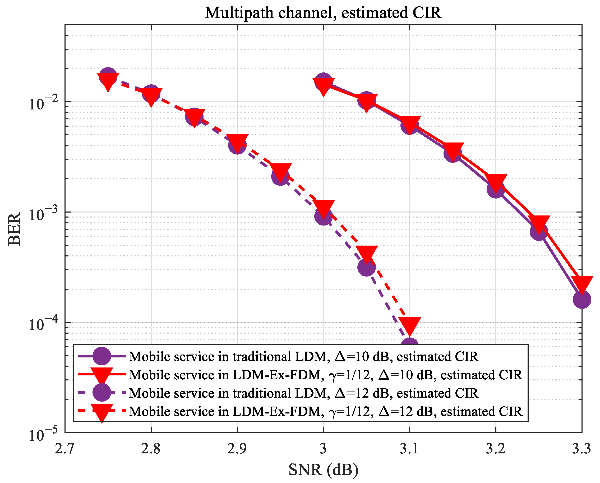
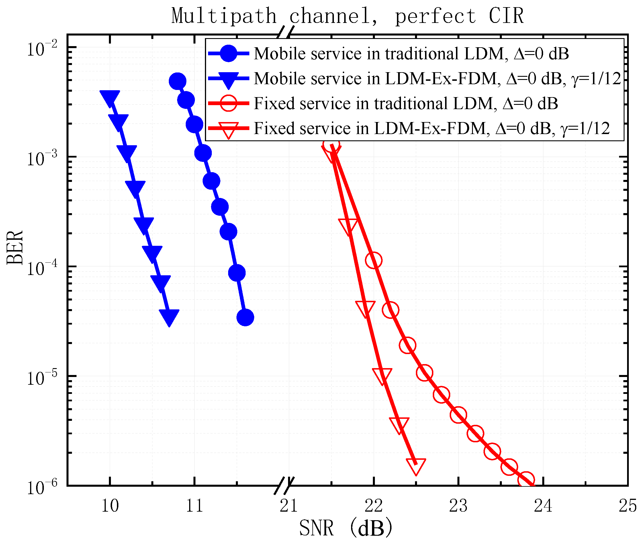
4.2. LDM-Ex-FDM Performance with Equal Interval Symbol Puncturing (EISP)
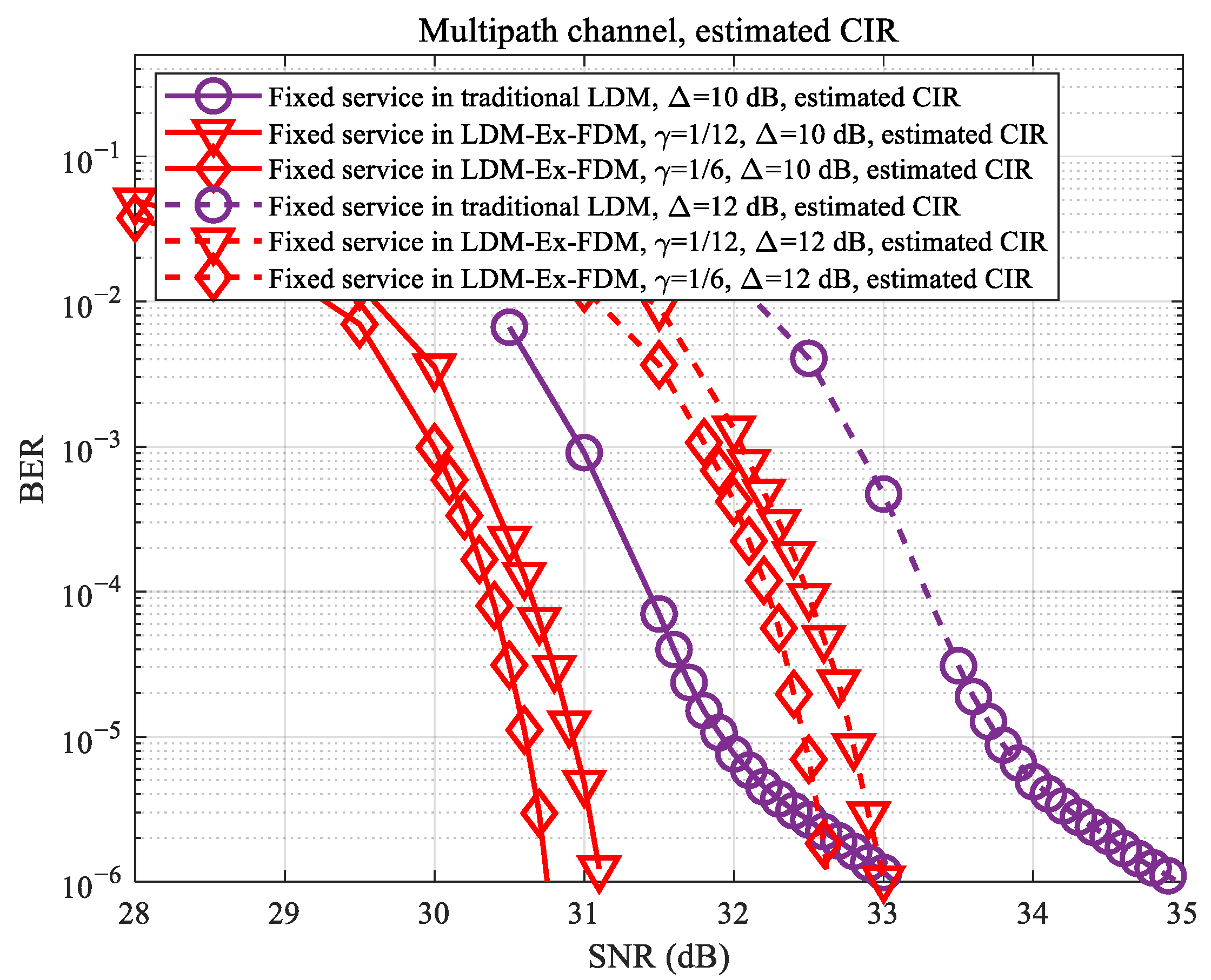
4.3. LDM-Ex-FDM Performance with Non-Equal Interval Symbol Puncturing (NEISP)
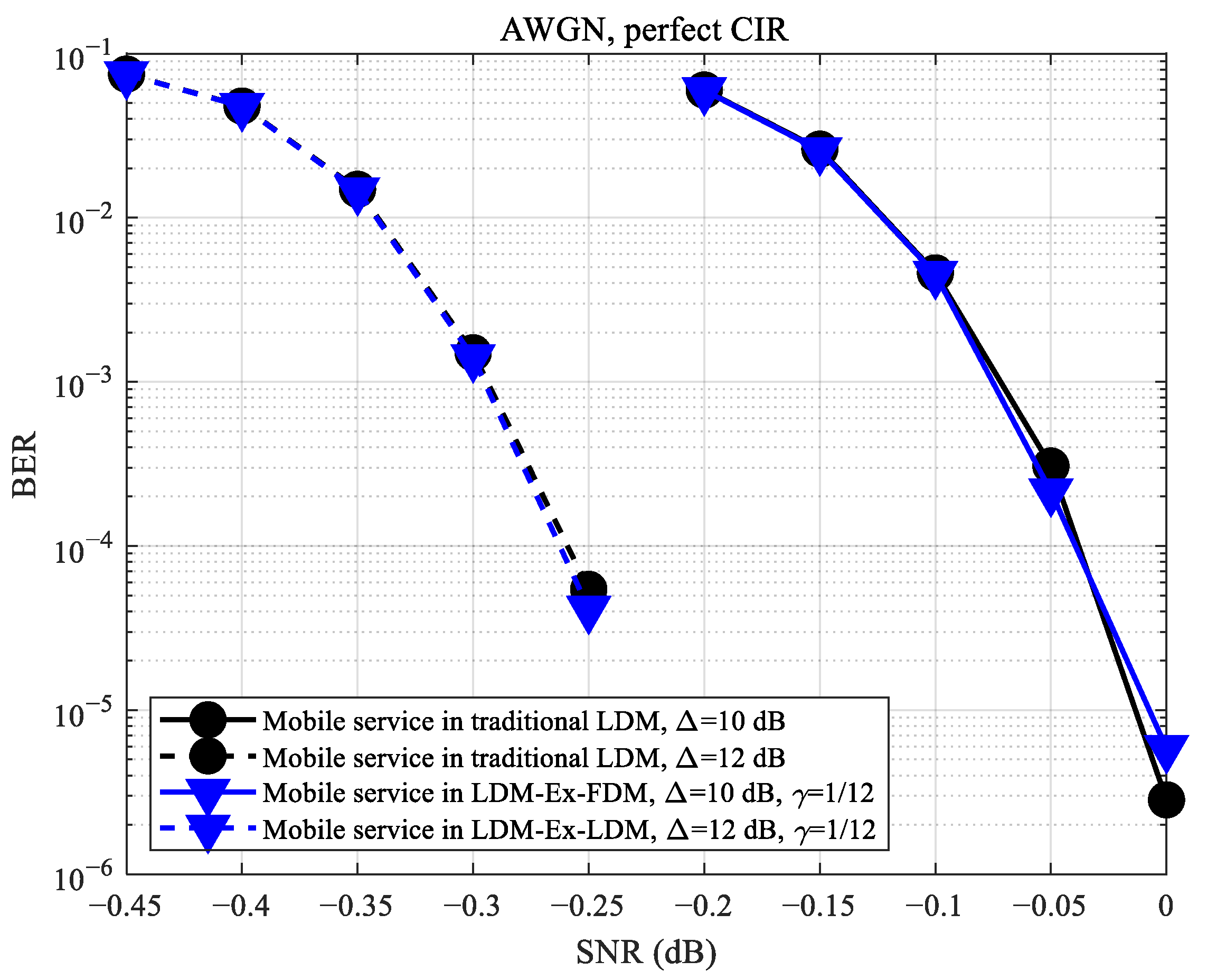
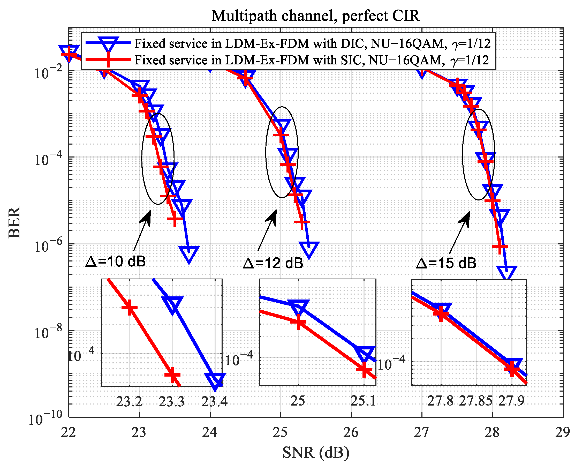
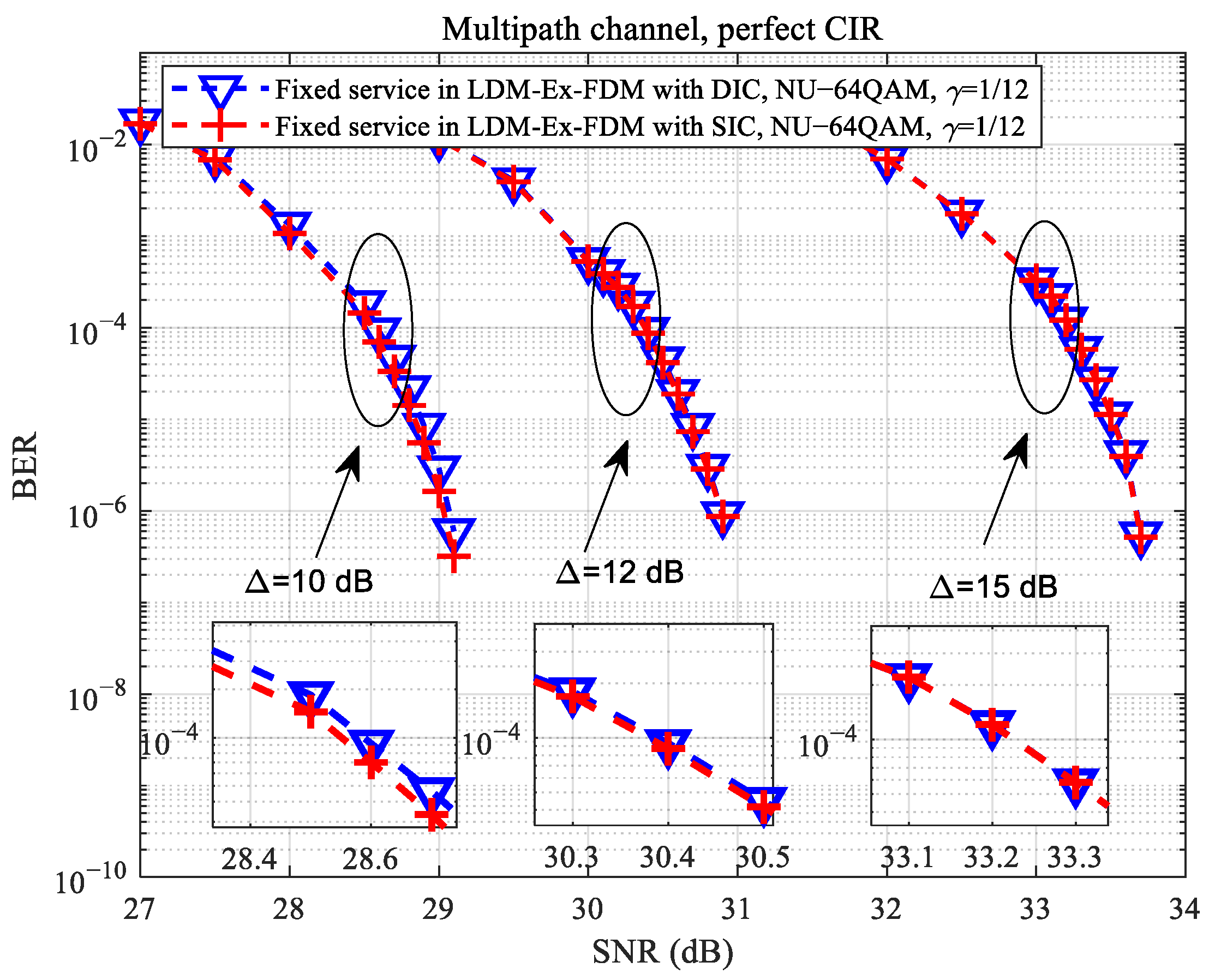
4.4. DIC Performance for the Fixed Reception
4.5. Further Discussions on the LDM-Ex-FDM Scheme
5. Conclusions
Author Contributions
Funding
Institutional Review Board Statement
Informed Consent Statement
Data Availability Statement
Conflicts of Interest
References
- Xue, Y.; Yang, H.; Pan, C.; Song, J. Field trial of UHDTV over Digital Television Terrestrial Broadcasting network. In Proceedings of the 2019 IEEE International Symposium on Broadband Multimedia Systems and Broadcasting (BMSB), Jeju, Korea, 5–7 June 2019; pp. 1–3. [Google Scholar]
- Eizmendi, I.; Velez, M.; Gómez-Barquero, D.; Morgade, J.; Baena-Lecuyer, V.; Slimani, M.; Zoellner, J. DVB-T2: The Second Generation of Terrestrial Digital Video Broadcasting System. IEEE Trans. Broadcast. 2014, 60, 258–271. [Google Scholar] [CrossRef]
- Pan, C.; Zhang, C.; Yang, H.; Wang, J.; Li, X. Results of the DTMB-A Field Trials in Hong Kong. In Proceedings of the 2019 International Conference on Engineering and Telecommunication (EnT), Dolgoprudny, Russia, 20–21 November 2019; pp. 1–4. [Google Scholar]
- Chernock, R.; Whitaker, J.C.; Wu, Y. ATSC 3.0—The Next Step in the Evolution of Digital Television. IEEE Trans. Broadcast. 2017, 63, 166–169. [Google Scholar] [CrossRef]
- Song, J.; Zhang, C.; Peng, K.; Wang, J.; Pan, C.; Yang, F.; Wang, J.; Yang, H.; Xue, Y.; Zhang, Y.; et al. Key Technologies and Measurements for DTMB-A System. IEEE Trans. Broadcast. 2019, 65, 53–64. [Google Scholar] [CrossRef]
- Jeon, S.; Kim, S.; Kim, J.; Yim, Z.; Seo, J. Field trial results of 4K-UHD over DVB-T2 single frequency network in Republic of Korea. In Proceedings of the 2016 IEEE International Symposium on Broadband Multimedia Systems and Broadcasting (BMSB), Nara, Japan, 1–3 June 2016; pp. 1–4. [Google Scholar]
- Zhang, L.; Wu, Y.; Li, W.; Salehian, K.; Lafleche, S.; Wang, X.; Park, S.I.; Kim, H.M.; Lee, J.; Hur, N.; et al. Layered-Division Multiplexing: An Enabling Technology for Multicast/Broadcast Service Delivery in 5G. IEEE Commun. Mag. 2018, 56, 82–90. [Google Scholar] [CrossRef]
- Zhang, L.; Li, W.; Wu, Y.; Xue, Y.; Sousa, E.; Park, S.; Lee, J.; Hur, N.; Kim, H. Using Non-Orthogonal Multiplexing in 5G-MBMS to Achieve Broadband-Broadcast Convergence With High Spectral Efficiency. IEEE Trans. Broadcast. 2020, 66, 490–502. [Google Scholar] [CrossRef]
- Zhang, L.; Wu, Y.; Li, W.; Park, S.; Lee, J.; Hur, N.; Kim, H. Using Layered-Division-Multiplexing to Achieve Enhanced Spectral Efficiency in 5G-MBMS. In Proceedings of the 2019 IEEE International Symposium on Broadband Multimedia Systems and Broadcasting (BMSB), Jeju, Korea, 5–7 June 2019; pp. 1–7. [Google Scholar]
- Islam, M.S.; Patwary, M.; Tait, R.; Peytchev, E. Layer division multiplexing for 5G DL transmission within ultra-dense heterogeneous networks. In Proceedings of the 2020 IEEE 91st Vehicular Technology Conference (VTC2020-Spring), Antwerp, Belgium, 25–28 May 2020; pp. 1–7. [Google Scholar]
- Regueiro, C.; Montalban, J.; Barrueco, J.; Velez, M.; Angueira, P.; Wu, Y.; Zhang, L.; Park, S.; Lee, J.; Kim, H.M. LDM Core Services Performance in ATSC 3.0. IEEE Trans. Broadcast. 2016, 62, 244–252. [Google Scholar] [CrossRef]
- Kim, H.J.; Kwon, S.; Kim, H.; Bae, J.; Hur, N. Performance Analysis of LDM and TDM systems for Three PLPs in DVB-T2. In Proceedings of the 2020 International Conference on Electronics, Information, and Communication (ICEIC), Barcelona, Spain, 19–22 January 2020; pp. 1–3. [Google Scholar]
- Ahn, S.; Park, S.; Lee, J.; Kwon, S.; Liml, B.; Kim, H.M.; Hur, N.; Wu, Y.; Zhang, L.; Li, W.; et al. Performance Evaluation of ATSC 3.0 Mobile Service with LDM/TDM Under TU-6 Channel. In Proceedings of the 2018 IEEE International Symposium on Broadband Multimedia Systems and Broadcasting (BMSB), Valencia, Spain, 6–8 June 2018; pp. 1–9. [Google Scholar]
- Park, S.; Lee, J.; Lim, B.; Kwon, S.; Seo, J.; Kim, H.M.; Hur, N.; Kim, J. Field Comparison Tests of LDM and TDM in ATSC 3.0. IEEE Trans. Broadcast. 2018, 64, 637–647. [Google Scholar] [CrossRef]
- Lee, J.; Park, S.; Kwon, S.; Lim, B.; Kim, H.M.; Montalbán, J.; Angueira, P.; Zhang, L.; Li, W.; Wu, Y.-Y.; et al. Multiple Service Configurations Based on Layered Division Multiplexing. IEEE Trans. Broadcast. 2017, 63, 267–274. [Google Scholar] [CrossRef]
- Zhang, L.; Li, W.; Wu, Y.; Salehian, K.; Laflèche, S.; Hong, Z.; Park, S.; Kim, H.M.; Lee, J.; Hur, N.; et al. Using Layered-Division-Multiplexing to Deliver Multi-Layer Mobile Services in ATSC 3.0. IEEE Trans. Broadcast. 2018, 65, 40–52. [Google Scholar] [CrossRef]
- Kim, H.; Kim, J.; Park, S.I.; Lee, J.; Kwon, S.; Hur, N. Capacity Analysis and Improvement of LDM-Based Multiple-PLP Configurations in ATSC 3.0. IEEE Trans. Broadcast. 2021, 1–13. [Google Scholar] [CrossRef]
- Kim, H.; Kim, J.; Park, S.I.; Lee, J.; Hur, N. Capacity Analysis for LDM-Based Multiple-PLP Configurations in ATSC 3.0. In Proceedings of the 2019 IEEE International Symposium on Broadband Multimedia Systems and Broadcasting (BMSB), Jeju, Korea, 5–7 June 2019; pp. 1–5. [Google Scholar]
- Caire, G.; Taricco, G.; Biglieri, E. Bit-interleaved coded modulation. IEEE Trans. Inf. Theory 1998, 44, 927–946. [Google Scholar] [CrossRef]
- Jin, H.; Peng, K.; Song, J. Backward Compatible Multiservice Transmission Over the DTMB System. IEEE Trans. Broadcast. 2014, 60, 499–510. [Google Scholar] [CrossRef]
- ATSC Standard: Physical Layer Protocol, Document A/322: 2020. January 2020. Available online: https://www.atsc.org/wp-content/uploads/2020/01/A322-2020-Physical-Layer-Protocol.pdf (accessed on 27 March 2021).


| Echo | Power (dB) | Time Delay (μs) |
|---|---|---|
| 1 | −3 | 0 |
| 2 | 0 | 0.2 |
| 3 | −2 | 0.5 |
| 4 | −6 | 1.6 |
| 5 | −8 | 2.3 |
| 6 | −10 | 5.0 |
| Parameter | Value |
|---|---|
| Fast Fourier transform (FFT) size | 16k |
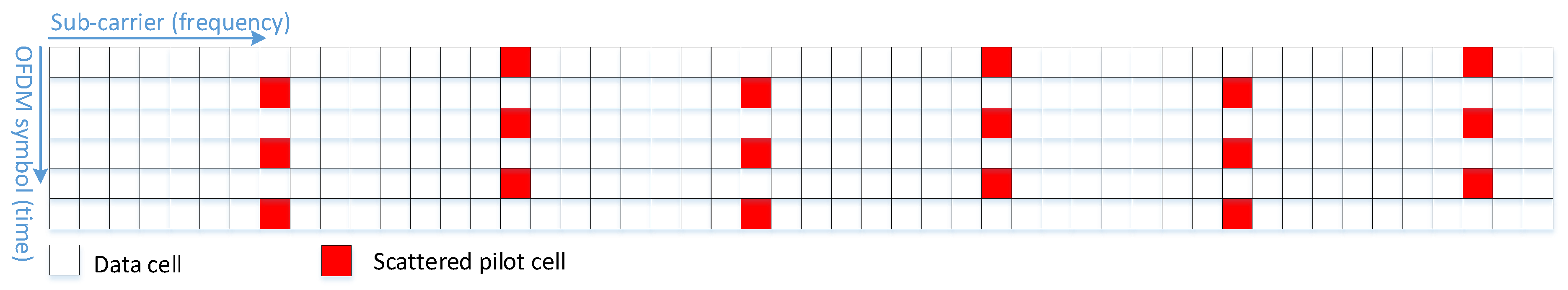
| Scattered pilot (SP) pattern | SP8_2 |
| Cyclic prefix (CP) | 1/16 |
| Core layer (CL) low-density parity-check (LDPC) code length | 16,200 |
| CL LDPC code rate | 5/15 |
| CL number of iterations | 50 |
| CL constellation | quadrature phase-shift keying (QPSK) |
| Enhanced layer (EL) LDPC code length | 16,200 |
| EL LDPC code rate | 11/15 |
| EL number of iterations | 50 |
| EL constellation | non-uniform (NU)−16 quadrature amplitude modulation (QAM), NU−64QAM |
| Puncturing rate () | 1/6, 1/12 |
| Injection level () | 10 dB, 12 dB, 15 dB |
| Scheme | Bit Rate for Mobile Service (QPSK-5/15) | Improvement of the BER Performance for Fixed Service under AWGN/Multipath Channel |
|---|---|---|
| Traditional LDM | 3.21 Mbps | - |
| LDM-Ex-FDM Puncturing Rate = 1/12 | 2.94 Mbps | 0.45 dB/1.8 dB |
| LDM-Ex-FDM Puncturing Rate = 1/6 | 2.67 Mbps | 0.90 dB/2.5 dB |
| Scheme | Transmitter | Receiver | Achieved Capacity | Complexity |
|---|---|---|---|---|
| layered division multiplexing (LDM) | LDM | successive interference cancellation (SIC) | low | low |
| time-layered division multiplexing (TLDM) | LDM, time-division multiplexing (TDM) | SIC | medium | medium |
| layered division multiplexing extension frequency-division multiplexing (LDM-Ex-FDM) | LDM, frequency-division multiplexing (FDM), equal interval symbol puncturing (EISP)/NEISP | SIC/ direct interference cancellation (DIC) | high | medium |
Publisher’s Note: MDPI stays neutral with regard to jurisdictional claims in published maps and institutional affiliations. |
© 2021 by the authors. Licensee MDPI, Basel, Switzerland. This article is an open access article distributed under the terms and conditions of the Creative Commons Attribution (CC BY) license (https://creativecommons.org/licenses/by/4.0/).
Share and Cite
Deng, X.; Bian, X.; Li, M. LDM-Ex-FDM: A Novel Multi-Service Transmission Scheme for the ATSC 3.0 System. Appl. Sci. 2021, 11, 3178. https://doi.org/10.3390/app11073178
Deng X, Bian X, Li M. LDM-Ex-FDM: A Novel Multi-Service Transmission Scheme for the ATSC 3.0 System. Applied Sciences. 2021; 11(7):3178. https://doi.org/10.3390/app11073178
Chicago/Turabian StyleDeng, Xianzheng, Xin Bian, and Mingqi Li. 2021. "LDM-Ex-FDM: A Novel Multi-Service Transmission Scheme for the ATSC 3.0 System" Applied Sciences 11, no. 7: 3178. https://doi.org/10.3390/app11073178
APA StyleDeng, X., Bian, X., & Li, M. (2021). LDM-Ex-FDM: A Novel Multi-Service Transmission Scheme for the ATSC 3.0 System. Applied Sciences, 11(7), 3178. https://doi.org/10.3390/app11073178