Article

Developing an Adaptive 3D Vertebrae Model of Scoliosis Patients for Customize Garment Design

1
ENSAIT- GEMTEX lab., Lille Université, 2 Allée Louise et Victor Champier, 59056 Roubaix, France
2
College of Textile and Clothing Engineering, Soochow University, 178 G.J. D. Road, Suzhou 215021, China
3
Ethiopian Institute of Textile & Fashion Technology, Bahir Dar University, P.O. Box 1037 Bahir Dar, Ethiopia
*
Author to whom correspondence should be addressed.
Appl. Sci. 2021, 11(7), 3171; https://doi.org/10.3390/app11073171
Submission received: 10 March 2021 / Revised: 24 March 2021 / Accepted: 26 March 2021 / Published: 2 April 2021
(This article belongs to the Special Issue XR-aided Design (XAD): Shaping the Future of CAD)

Abstract

:

Featured Application

The researchers propose a new design technique to develop an adaptive 3D model for a spine affected by scoliosis. We used 3D scanning technologies to create a model accurate enough for various applications in the textile industry. The developed adapted 3D model can integrate with the complete skeleton and body shapes of patients with scoliosis, which should facilitate the process of designing comfortable, and high-performance clothing.

Abstract

Scoliosis is one of the most frequently occurring morphological problems in people. People with such an abnormal curve of the spine face a huge problem, not only from the medical point of view but also from that of garment design and production processes. The current paper brings a novel designing technique to develop an adaptive 3D model of the complicated anatomical shape of the human vertebrae using 3D digitization technologies. Even though it is not as accurate as scanning approaches, it is accurate enough for several applications, including visualization and constructing statistical shape models. Thus, the adaptive model will further integrate with the full skeleton and then to the body shapes of scoliosis patients, not only for an easy garment design process but also to produce comfortable and high-performance garments. The model has also the benefit of adjusting for each tissue to all kinds of spine parameters, such as the height and the angles of the bones and disks (especially the three characteristic planes: sagittal, coronal, and transverse). Thus, the full adaptive skeleton model and later its garment design system, considering the current adaptive vertebrae model for fitted, comfortable and well-performing scoliosis patients garment products, could be developed.

1. Introduction

Scoliosis is a multifactorial three-dimensional (3D) spinal deformity and directly related to vertebral deviations in the coronal, sagittal, and horizontal planes. It is also a sideways curvature of the spine that occurs most often during the growth spurt before puberty. Uneven shoulders (one shoulder blade that appears more prominent than the other), uneven waist, and one hip higher than the other are some of the symptoms of scoliosis. It occurs relatively frequently in the general population, depending on the magnitude of the curve being described. Naturally, the human spine is a central nervous system which encompasses the area from the lower back to the brain. A spinal cord, made of myelin-sheathed nerve fibers, is the outer layer of the spine which helps to send different impulses (pain, pressure, and other stimuli). Basically, the cord is interlocked and protected by the spinal column (vertebrae) which comprises a total of 33 bones. The S-shaped spine has two regions: the slight concave curve (the cervical and lumbar) and the convex curve (the thoracic and sacral). The physiological S-shape allows the human body to maintain balance, absorb shock and allow a range of motion by working like a coiled spring. The strong fibrous ligaments in the central nervous system are used to protect the discs, stabilize the spine, and hold together the vertebrae. The ligaments in the spine are of three types: the ligamentum flavum (attaches the lamina of every vertebra), the posterior longitudinal ligament and the anterior longitudinal ligament, which mainly prevent excessive vertebral bone movement. There are also two types of muscles in the spine, namely the extensors (which allow people to lift objects and stand up) and the flexors (allow people to not only bend forward and flex but also control the arch in the lower back and stabilize the spine). On the contrary, when viewing the spinal column from the rear (posterior), the spine appears vertically straight from the neck to the tailbone. The standard curves are termed lordosis and kyphosis; however, the natural curves should not be mistaken for spinal disorders, also called lordosis and kyphosis. Lordosis and kyphosis are terms that are used to refer to specific spinal disorders [1,2]. The most common quantification of scoliosis is the Cobb angle, proposed initially by the American orthopedic surgeon John Robert Cobb [3]. The Cobb angle, which is adopted as the standard quantification of scoliosis by the Scoliosis Research Society (SRS), founded in 1966, involves estimating the angle between the two tangents of the upper and lower endplates of the upper and lower end vertebra, respectively [4]. Most scoliosis curves greater than 25 degrees, can be treated not operatively if they are severe. Boys and girls should be examined every 6–9 months; curvatures less than 30 degrees will not progress after the child is skeletally mature. Once this has been established, scoliosis screening and monitoring can usually be stopped. However, with greater curvatures, the curvature may progress at about one degree per year in adults [5]. In general, the progression of an idiopathic scoliotic deformity with a Cobb angle of between 25 and 40 degrees can be stopped by brace treatment, provided that the generally acknowledged criteria for the treatment concerning skeletal growth of the individual are respected [6]. Spine pathology may include various diseases of the back or spine. The Pisa syndrome is a reversible lateral flexion of the trunk and a tendency to bend to one side. It is a recurrent and often debilitating complication of Parkinson’s disease and has also been described in several abnormal forms of Parkinson’s and neurodegenerative disorders after exposure to medication and surgery. Although no fixed diagnostic criteria are available for Pisa syndrome, in most studies, cutting at least 10 degrees of lateral flexion to diagnose the syndrome is optional [7,8].
Apart from the medical and surgical training programs, the advantages of having a three-dimension model of the spine and human body are that it can be used for designing specific performance clothes. Developing intimate and specialized apparel products is a very complex process that requires achieving proper sizing, fit and comfort. Ill-fitting and insufficiently comfortable garments could also lead to both decreased performance, unpleasant appearance, and musculoskeletal pain.
Our current research focuses on the modeling of the vertebra to gain enough knowledge about the skeleton and its anatomy through understanding the different divisions and functionalities of the vertebrae. This makes it possible to find a basic generic model on which to graft the morphological specificities of each group in the three morphological variants. Such a model is developed by considering the root of these specific curves instead of focusing on the human body. In the future, integrations of the full skeleton, anthropometric point, and the connection between the morphologic point and anthropometric point would give enough information for further applications in the customizations of garment design for scoliosis patients.

2. Related Literature Review

Nowadays, computer aided design (CAD) with various analytical tools is used to generate practical designs for most engineering applications [9], including garment design. For such a purpose, several efforts have been made on generating an accurate digital 3D human model for analyzing the effects between humans and products. Modeling the external human body shape is one of the key techniques for realizing proper product design, which is required for better fitness, accuracy, comfort, and performance. Several researchers have also proposed a human body model development solution based on parameterization algorithms. For example, a human body model template was proposed through anthropometric measurement [10]. A 3D human body shape, through a set of semantic values using an exemplar-based method, was also generated [11]. Another study constructed a 3D human model from 2D images [12], which is a cost-effective approach to visualizing a digital human in a virtual environment. A parametrization approach to human bodies using unorganized cloud points has been also proposed for generating new models [13]. Such techniques are used for not only optimizing and testing the functionality of the designs, but also to assist in generating manufacturing information efficiently. It is also used for shortening the product development cycle by improving size accuracy, fitness, pattern accuracy and grading sampling, as it is able to draft a design virtually to reduce material waste. Even though the spine anatomy is challenging to master, some researchers have used software to convert medical images to 3D models through the process of segmentation. Such a process helps to create educational material for 3D visualization of the spine. The 3D models are then optimized using 3Matic, the computer-aided design (CAD) counterpart to Mimics [14,15]. In previous research, cervical spine images taken from CT scanners were used as datasets to detect the bones and mimics was used to create a 3D model [16,17]. Two-dimensional images are limited in their ability to assess vertebral rotation and pelvic parameters, which is why an additional CT is sometimes needed to increase the accuracy of the measurements [18,19]. Besides radiation exposure, CT’s main disadvantage is the patient’s supine positioning during the examination [20], which leads to considerable differences in vertebral rotation and the extent of scoliosis compared to an upright posture. The new Enterprise Operating System (EOS)-technology based on a low-dose X-ray system allows 3D modeling of the spine based on 2-dimensional X-rays acquired of the upright position, providing information about scoliosis and sagittal balance [20]; the EOS images are found to be superior or equivalent to conventional radiographs in terms of global image quality and structure visibility with up to nine times lower radiation [21,22]. The sterEOS software enables 3D modeling of the bone envelope based on anatomic references defined by the reader and provides specific clinical parameters [23]. Some studies also analyzed scoliosis through various methods; for example, based on the surface of the trunk, the scoliosis curve was analyzed in 3D using a noninvasive multi-head digitizing system [24]. Another study also evaluated the three-dimensional (3D) characteristics of spine deformity in patients with non-idiopathic scoliosis compared with those observed in patients with adolescent idiopathic scoliosis (AIS) [25]. A new top-view was developed for the 12 patients with idiopathic scoliosis to display their spine (as if the observer were above and looking down on the patient) using computerized spinal analysis [26].
Apart from the medical point of view, with the morphological figures of disabled people, they face a great problem in finding personalized products, including clothing, footwear and furniture [27]. Recent studies have highlighted the importance of reducing the exertion of human workers in manual handling and lifting tasks by using wearable exoskeletons. For example, one study used and investigated the different configurations of a trunk exoskeleton in terms of hinge joint positions to find the best ones for reducing human exertion, considering both human joints loads and interface forces [28]. Another research also introduced a new wearable robot design approach continuum with a soft exoskeleton to tackle the existing exoskeletons which are obtrusive, which can cause ergonomic risk [29].
Moreover, clothing products that do not consider people with atypical morphology have significantly reduced the quality of life and social participation of this group. They are also forced to use different clothing design systems than people with typical morphology who use a standard sizing system. This customized requirement for clothing makes the clothing designing system very complex and very challenging and leads to unaffordable prices. Higher prices with bad quality and limited diversification create important barriers for adapted products [30]. Therefore, the traditional two-dimensional (2D) pattern design and garment development systems used for the normal body shape may not satisfy the requirements of disabled peoples, such as in the case of scoliosis. Thus, developing and using a unique garment design system is very vital to give the garment not only high-performance but also good comfort and fit. Nowadays, a 3D virtual mannequin model using three-dimensional computer-aided-design (CAD) technology is a commonly used method to obtain anthropometry information, declare ergonomics and provide appropriate products for various kinds of consumers [31]. For example, 3D design software has been used to significantly improve the garment design process by overcoming the limitations of ordinary 2D design methods through developing a virtual 3D mannequin model [32,33,34]. Some researchers are also dedicated to modeling a non-adaptive 3D human body based on a generic reference model [13,35,36,37]. A parameterized model of the morphotype is based on a model surface representation defined by many sections of curves derived from human body scanning. The concept of a set model of the morphotype occurs in these curves’ choice and positions and the relationship between them, and the data from the measurement campaign [36,38,39]. Through these morphologic curves and anthropometric points, a basic pattern of the body will be created, globally. Some research has also used the correspondence between scanner data and the virtual model of the human body by converting the scanned body mesh into a volumetric model [40]. Others have proposed an adaptive model which can be adjusted according to different human bodies [41].
However, all these improvements were not executable for scoliosis cases; even the recent adaptive methodology for parametrically designed garments on virtual mannequins, which can facilitate design, analysis, and, hence, ensure a good consumer fit [18], is not any more adaptive for people with unusual curves in the body. Recently, a researcher dedicatedly worked to develop a full garment designing system for the specific consumer’s morphological shape with atypical physical deformations using non-adaptive 3D human modeling [42,43,44]. Such a modeling process is very time-consuming for generating garments, not only for when the patient’s body changes over time but also for patients with different morphologic problems. Designing a garment for the different variations in patients with different morphological problems is a huge problem. This could be solved by integrating the full skeleton, anthropometric point, in general; it is a position of the bone, and it is the connection between the morphologic point and anthropometric point during the modeling process. Thus, different anthropometric points from the position of bones will provide enough information to create a garment.

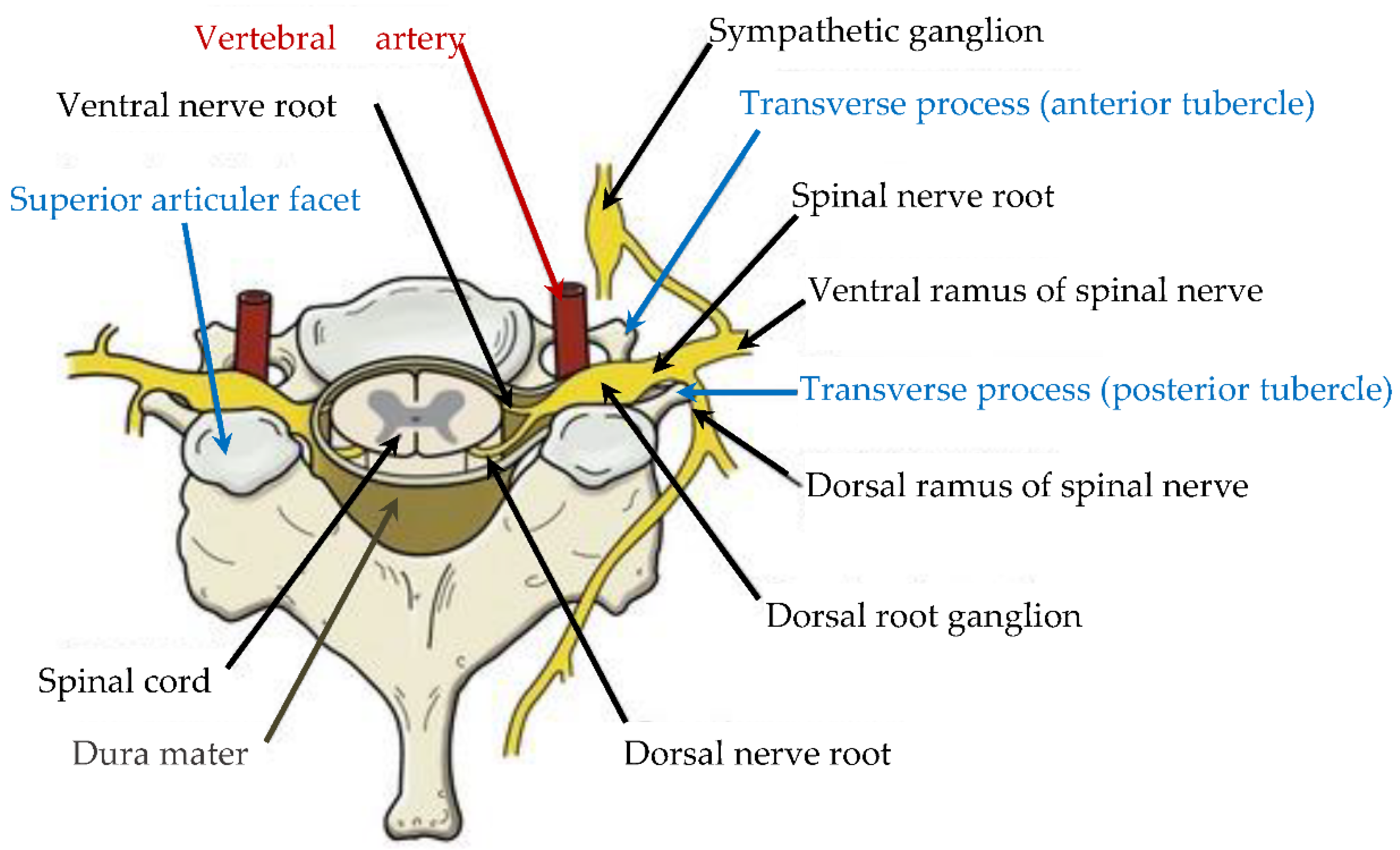
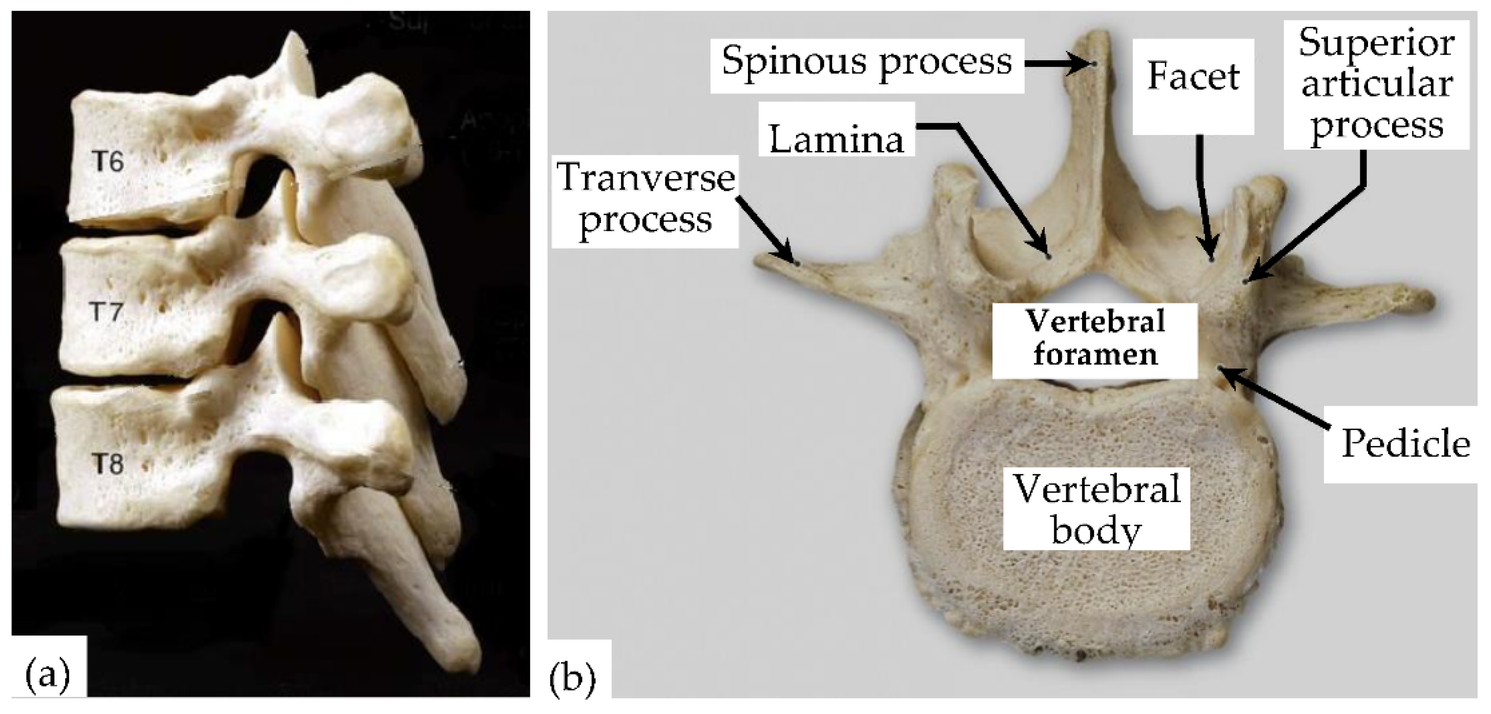
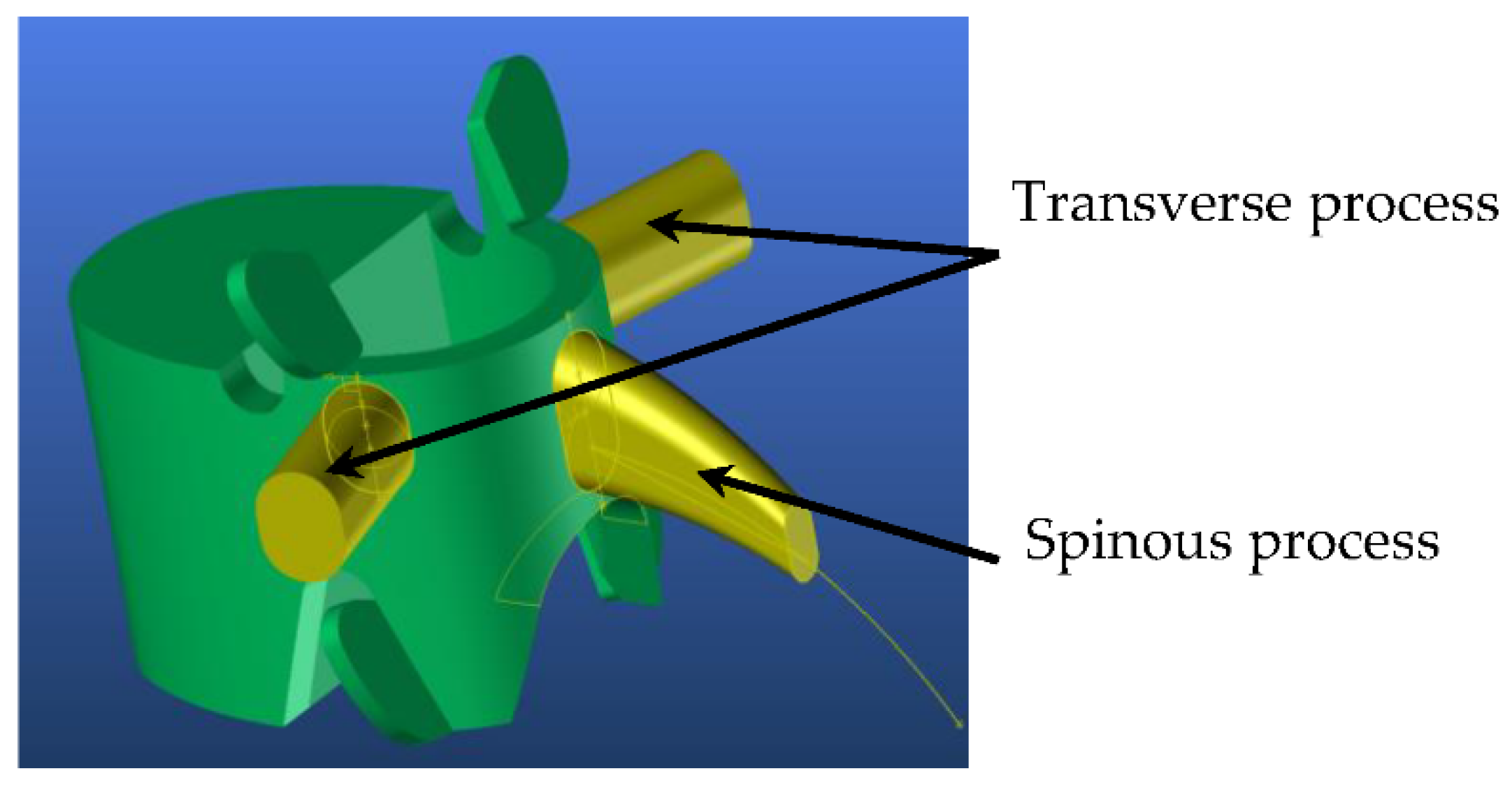
3. Anatomical Description and Generic Model of Different Vertebrae Morphology

Spine modeling requires a thorough analysis of the different functionalities of the vertebrae, which strongly influence the morphology of each of them. The goal is to understand why it is divided into three distinct groups (lumbar, dorsal, and cervical vertebrae), which generate three types of morphology [45,46]. Given that some features could be expected, it is possible to find a basic generic model on which to graft the morphological specificities of each group. However, the C1 and C2 vertebrae have different morphologies and biomechanics [47]. It is also indicated that the axial trabecular architecture of the dens appears to be crucial for the physiological and biomechanical function of the C1-2 joint. One of the studies demonstrated the presence of a Y-shaped trabecular structure of the dens on the axial CT and described its anatomical and biomechanical implications [48]; it would have a generic model that could be derived in three morphological variants. The spine not only provides vertical stability in the trunk and neck, but it also has a protective role for sensitive organs such as the spinal cord, ventral and dorsal nerve roots, nerve roots of the spine, and vertebral arteries. The spine’s modeling must consider all morphological constraints imposed by different functional, mobility, and stability criteria. Each vertebra has an anterior and posterior arch. The posterior arch forms a hole called the foramen and the spinal cord passes through the foramen of each vertebra. The vertebral bodies defined by the anterior arches are connected among themselves by the intervertebral discs. The posterior arch is composed of the pedicles, laminae, and processes. The pedicles can be represented by two short cylinders of bone that extend from the vertebral body. Laminae are two plates of bones that form the walls of the posterior arch. The transverse processes extend out on either side of the laminae. The spinous process is very variable according to the function of the vertebra type. It can be felt through the skin in the body’s back. The spinous process will allow for defining the exact position of the spine when inserted into the body. Figure 1 schematizes the relationship between the spinal cord and the nerve roots coming out on either side of the spine.
This connection towards the whole nervous system acts on the morphology of the vertebrae by excavations. Similarly, each vertebra’s stacking and adjustment (Figure 2a) on top of each other contributes strongly to their morphology by the prominences leading to the upper and lower facets representing the joint process contact zones. Other contact zones are located at the intervertebral disc level, whose role is to ensure the spinal column’s damping against heavy loads and facilitate mobility or the 3D deformation of the spine. The spine’s modeling must consider all these morphological constraints imposed by these different functional, mobility, and stability criteria. Other physical constraints are more specific to the group to which the vertebra belongs. For example, the lumbar rachis has a protective role in the spinal cord but also one of support. It guarantees the posture of the trunk and standing support. For this, the lumbar vertebrae structure is robust to allow the trunk to twist, bend or stretch.
On the other hand, the dorsal rachis is not very mobile and carries the thoracic cage. For this purpose, it is provided with a specific transverse process and costovertebral joint to allow each rib’s hanging and positioning. As far as the cervical rachis is concerned, it has excellent mobility like the lumbar rachis without having this important supporting role. Its particularity is that each cervical vertebra presents notable differences that will lead to different vertebrae models for this rachis. Although the vertebrae have slightly different appearances, they all have the same basic structures with the same names as shown in the previous analysis. The lumbar vertebrae have the particularity of grouping all the common points of each vertebra because they represent the spine’s starting point. Thereby, the vertebra’s generic model can be set up from the morphology of the lumbar vertebrae described below (Figure 2b).

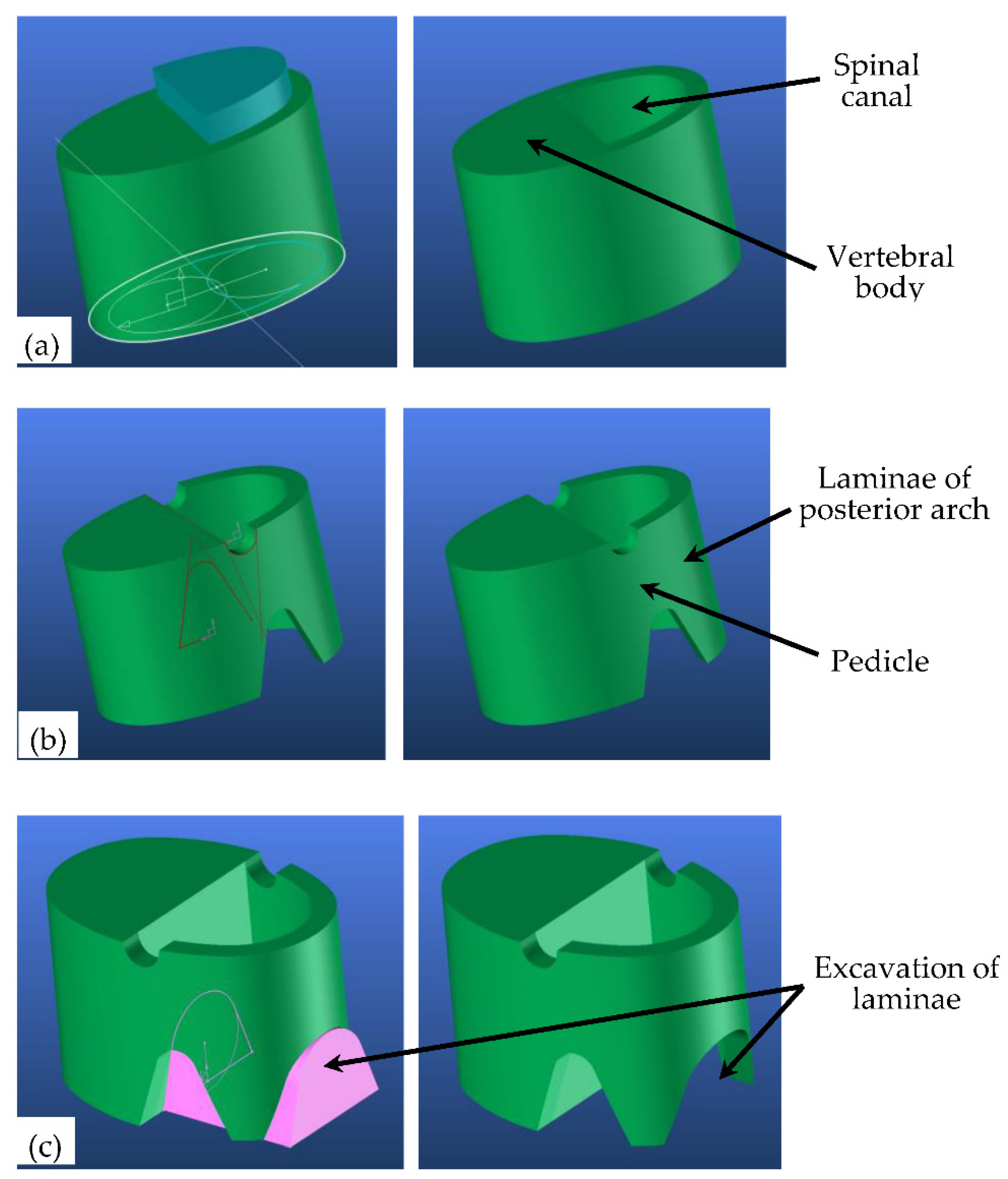
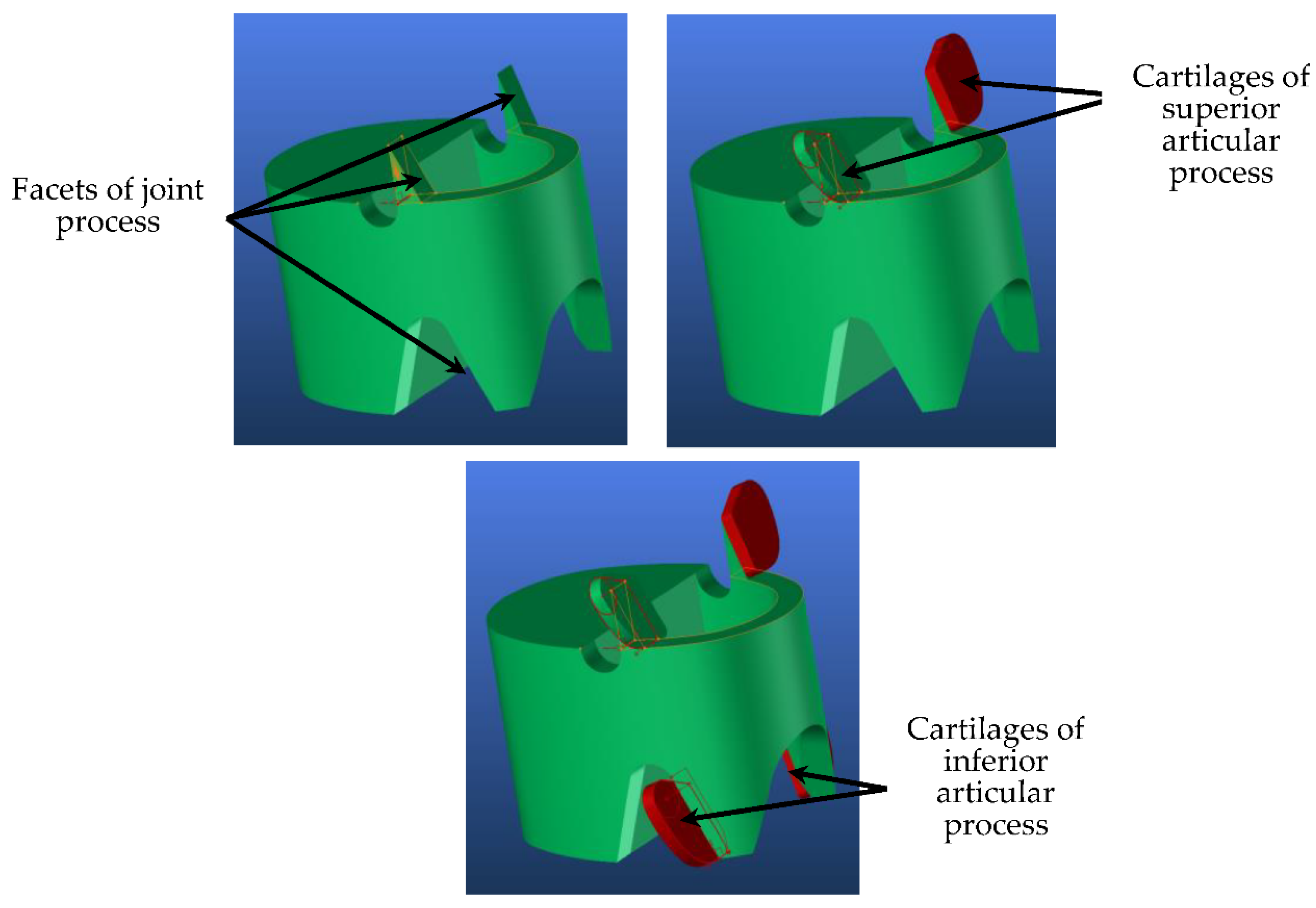
4. 3D Adaptive Vertebrae Model

4.1. Generic Model

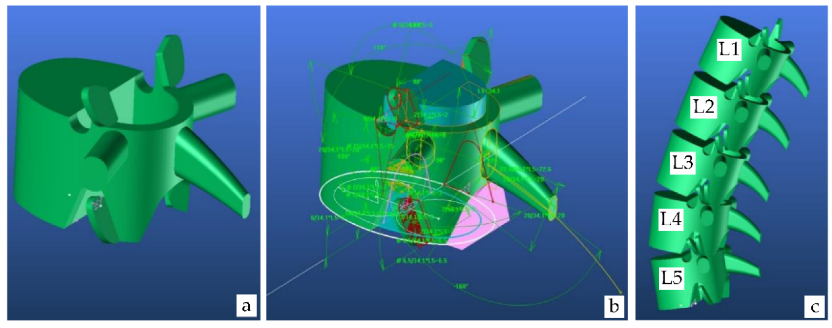
4.1.1. Lumbar Vertebrae Model

The modeling process of a lumbar vertebra begins with the creation of its vertebral body (Figure 3a). First, an extruded circle at the vertebra’s height creates the two upper and lower vertebral plates and the volume of the vertebral body. Another eccentric circle is partially used to define the spinal canal (blue shape).
The diameters of these two circles are proportional to their extrusion height to adjust their dimension to the lumbar vertebrae number. Thus, the vertebra volume is managed by its height, which is itself defined proportionally to the total length of the spine according to an anthropometric report that could later be specified. The next step is to understand deeply the lateral part of the 3D model into designing the pedicles (Figure 3b). Two half-circles extended on each side by two inclined lines (red) make it possible to define the dimensions of the pedicles’ upper and lower openings. The diameters of the circles and the inclination of the lines associated with these circles allow the pedicles to be adjusted according to the height of the vertebra. The figure clearly shows the vertebral arch composed of the two pedicles and the two frontal laminae. A recess has been made in the laminae of the posterior arch to get as close as possible to their final shape (Figure 3c). Then, the superior articular process is defined. It is positioned at the frontal end of the upper part of the pedicle. This inserted element allows us to manage the height, width, and inclination of the superior articular process.
The inclined facets are then covered with two cartilages, which are morphologically managed by four circles located at the four corners of the basic surface, which generates the cartilage volume (red) (Figure 4). Concerning the inferior articular process, the inclined facets are of the lower part of the pedicle. The process of modeling the lumbar vertebra begins with the creation of its vertebral body and then the superior articular process is defined.
It is positioned at the frontal end of the upper part of the pedicle and this inserted element allows the method to manage the height, width, and inclination of the superior articular process. An essential element in the vertebrae’s overall dimensioning is the spinous process with a curved and long shape. Concerning the inferior articular process, the inclined facets of the lower part of the pedicle are also covered with two cartilages that are managed in the same way as the upper cartilages since the stacking of the different vertebrae imposes a perfect alignment of the upper and lower part of the pedicle and the upper articular process. The transverse process is positioned laterally and perpendicularly to the vertebra’s upper surface (Figure 5).
Thus, it is possible to manage the transverse process by its frontal and dorsal inclination, its volume by the two basic circles that generate this volume, and its extrusion length. An important element in the vertebrae overall dimensioning is the spinous process with a curved and long shape (Figure 5). To do this, a guide curve is developed that manages both the length and curvature of the spinous process. A base surface created by two eccentric circles runs perpendicularly along this curve, gradually reducing when it reaches the spinal process’s tip. Finally, Figure 6a shows our final generic model representing the three-dimensionally controllable lumbar vertebrae by the different green dimensions (Figure 6b. These dimensions are concerning each other, these dimensions have only one parameter, allowing this model to evolve from the lumbar vertebra L5 to the lumbar vertebra L1 (Figure 6c). Even though the angle between L1 to L5 of the lumbar vertebrae change in humans, the study considers similar and corresponding angle evolutions among the different lumbar vertebrae.

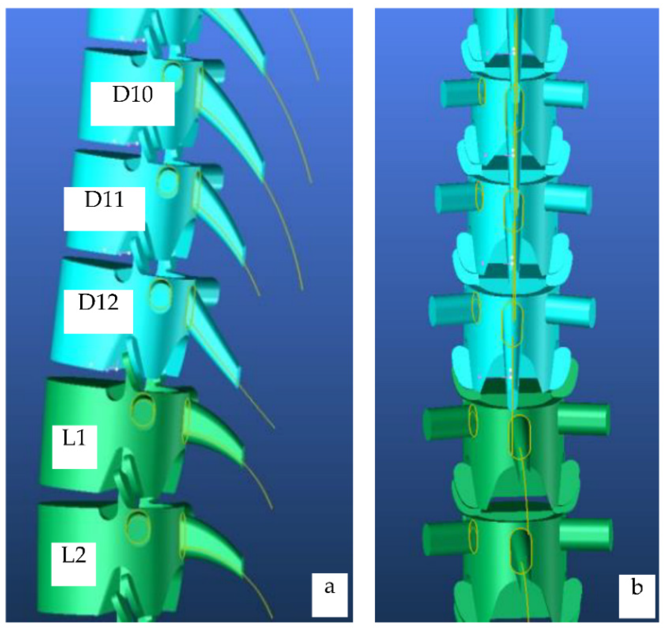
4.1.2. Dorsal Vertebrae Model

The dorsal vertebra model is like the lumbar vertebra model. Apart from the size of the vertebrae, which gradually reduces from the D12 to the D1, they differ morphologically from the lumbar vertebrae in their spinous process; they are straighter for the D12, more curved and shorter for the D11, and more marked and imposing in length for the following ones (D10 to D1) (Figur 7a). To do this, the curvature of the guideline that gives this curved shape was developed. Another difference is in the transverse process, which is shorter and slightly closer to the spinous process (Figure 7b).

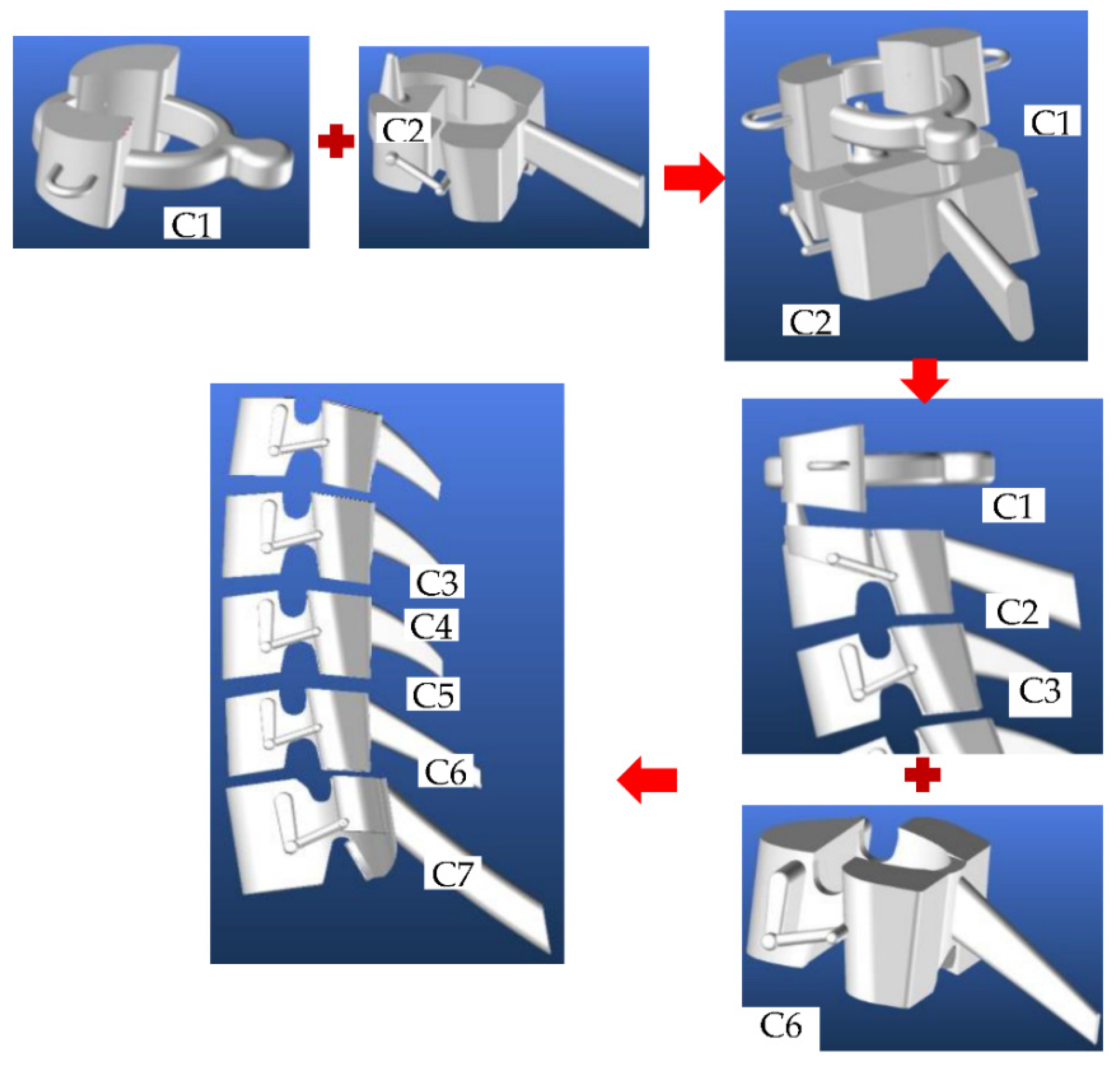
4.1.3. Cervical Vertebrae Model

The modeling of the cervical vertebrae is overly complicated because each of them presents morphological differences. The search for similarities, which will later allow us to set up a generic model that can be modified according to the vertebra, shows that each vertebra has transverse foramina located within the transverse processes. The length and shape of the spinous process are also extremely specific from one vertebra to another. These similarities and distinctions lead us to consider four types of models. The first is dedicated to the C7, the second is common between the C6, C5, C4, and C3, the third model is specific to the C2 and the last model is exclusively dedicated to the C1 (Figure 8)

5. Results and Discussion

5.1. Virtual and Real Model of Cervical Vertebrae

The developed models do not pretend to represent vertebrae’s morphology correctly, but they aim to be dimensionally and functionally close to them. The dimensional aspect will only be carried out later, on individual specific blocks of the models. For example, the height, width, and weight of the vertebral body, and the length of the overflow towards the outside of the transverse processes of the spinous process will be parameters that help to obtain, during the image processing in the frontal and coronal plane, radiographs of the patient’s spine. Thus, they are dynamic models that have the faculty to approach the shape of the vertebrae thanks to the specific parameter settings of each of them that apply for any type of person, of typical or atypical morphology. Figure 9a,b shows the generic model developed from the lumbar vertebrae’s shape, and its specifications are very close to reality.
It can be criticized that the developed model’s position of the articular processes could be farthest back to the posterior part. However, this could not be a problem since the joint process can slide and follow the upper curve of the posterior arch’s laminae. Thus, the current model, which was slightly modified to adapt to the dorsal vertebrae, follows exactly the shape of the last. As observed in Figure 9c,d, the stacking of one over the other of D6, D7 and D8 is well achieved. A critique could be made on the spinous process’s shape, which tends to be firmly downward in the real case. Still, the developed model manages these kinds of aspects by modifying the shape and the inclination of the director, which defines this 3D shape. As already mentioned, the cervical vertebrae also have a specific articular process, which leads to the strong overlapping in each other. The real figures of the seven cervical vertebrae stacking in Figure 10a shows that the developed model is very close to reality. Each specific model integrates very well among all the morphological specificities of their category. For example, C7 has a critical spinous and transverse process which is very different from that of the generic lumbar and dorsal vertebrae models (Figure 10b,c). The C6, C5, C4, C3, C4, and C3 have also a slightly smaller vertebral body, which leads to a more important spinal process (Figure 10d,e). The articular process is higher than with the C7 (Figure 10a). The C2 is very imposing, following the integration of the two articular processes designed laterally on the vertebral body (Figure 10f,g). The dens are perfectly positioned on the axis of the vertebral body. The transverse processes follow, perfectly, the external morphology of the vertebral body. The whole gives a compact overall shape following the morphology of the C2. The spinous process is more noticeable at its tip but needs to be reduced by adjusting the director curve’s length as of the dorsal vertebrae; the modeling of the C1 by a ring is very representative of it (Figure 10h,i).
The addition and proper sizing of the joint process give its overall shape. The two transversal approaches properly complete the whole part. As it is already noticed, the spinal column is an exact stack of vertebrae evolving according to a defined curve in a 3D space. This curve characterizes the morphology of the person, in particular, the posture. To describe the 3D path of this kind of curve, it was chosen to be portrayed in the two main planes, namely the sagittal plane and the coronal plane. Our model segmented such a path into 24 portions represented by a set of lines on which it will align the 24 vertebrae of the spine. T represents the type of vertebra (C: cervical, D: dorsal, L: lumbar) and n the number of vertebrae in its category. Each line is defined by polar coordinates (ltn, αtn, βtn) located at the lower end of the line: ltn represents the length of the line equal to the height of the vertebra and its upper intervertebral disc and αtn and βtn respectively represent the two polar angles of the lines projected on the sagittal and coronal planes. It is important to note that the rising dependency of vertebrae from their stacking is created when developing straight lines one after the other in the rising direction of the spine. This dependence is obtained by creating the coordinate system of the next (upper) vertebra at the end of the right of the previous (lower) vertebra. The total length Lt of the spine is the only parameter to give the model for parameterizing the length ltn of each vertebra/disk. The modeling process used the vertebral ratios of the research work as shown in Table 1 [14,49]. To consider the 3D deformation of the spine in atypical cases of scoliosis, each vertebra can rotate by an angle γtn on the axis of the line assigned to it (Figure 10a). The first tests were carried out with a spine perfectly aligned, vertically, with different lengths, Lt (Figure 10b). The test used a different length of a spine from Lt = 750 mm to Lt = 550 mm. These values are very representative of reality. The results in Figure 11 shows that all vertebrae re-align perfectly with each other while reducing their volume. The first part of the table represents each vertebra’s height based on the ratios. The three other tests separately show the spinal column’s deformation in the three characteristic planes: sagittal, coronal, and transverse.
These deformations were carried out with the same length of spine, Lt = 750 mm, to show its impact on the overall height of the person following the first two deformations (with the third not affecting the particular height). This parametric independence will be beneficial to represent all types of scoliosis deformations in the next process. Table 2 represents the rotation angle of each vertebra in the sagittal plane. The third part of Table 2 represents the angle of rotation of each vertebra in the coronal plane. The last one represents the rotation of each vertebra in its transverse plane, i.e., its rotation on itself.

5.2. Developments of Adaptive Vertebra Model in a Body

The advantage of our adaptive spine model is its ability to integrate with the human body with or without scoliosis. To facilitate such a process, a patient with a specific deformity was scanned in the Human Solutions body scanner. After attaining the scanned body shape, the data was imported into software called Rapid Form. This software allows us to edit and correct the defects of the imported 3D meshed object. Later, the cleaned data from the scanner were then imported from the person’s surface model, representing the outer shell of their body, into the 3D Design Concept software that was used to create our spine model. The integration of the spine into this body was carried out in several stages. The first step was to assign the correct Lt value to the spine model (Table 2). Since the person was scanned by the EOS scanner, the value was calculated as the height Lt of the spine (Lt = 620 mm). The second step was to position the start of the spine in the right place. Vertebra L5 was our reference vertebra, which was placed as close as possible on the sacrum’s high part. This position is somewhat imprecise vertically but is more easily located between the two buttocks. This position will evolve slightly until the positioned C7 vertebra is achieved in its right position, a position where it is very easily perceptible.
The third step was to follow the path of the vertebral column by gradually gluing the spinous process of each vertebra into the significant hollow which was created at the back of the body. The angular parameters of each vertebra αtn, βtn have been adjusted gradually from bottom to top (Table 3).
The parameters γtn have been set to zero since it is impossible to determine their specific value at this point. However, the analysis of the two coronal views shows that the double deflection of the spine forming and S is similar. Since there was a front view obtained from the EOS scanner and a back view in the Design concept software, it is possible to have a symmetrical visual of the S orientation. The analysis of the two sagittal views shows that the path of the spine in the patient’s back follows in an identical way to the significant hollow. Figure 12 shows the values obtained for a particular patient using the EOS images and the integrations of the model spine in the patient’s body.

6. Conclusions

This study illustrates a method for constructing an adaptive 3D model of a complicated anatomical shape of the human vertebrae, which is accurate enough for several applications including visualization and constructing statistical shape models. The models are also used to perfectly detect different anthropometric points and morphology curves on the breast to obtain unique points and scapula. Especial points on the scapula play an essential role in creating an article of clothing for scoliosis patients. For this, the study explained previous models of the spine and the methods for obtaining data from radiologic images. The study also discusses, in detail, how to construct a model of the spine by investigating and understanding the different functionalities of the vertebrae, especially the lumbar, dorsal, and cervical part. Using the different vertebrae functionalities, an innovative 3D design process was introduced to develop the 3D adaptive model. For each case, the developed adaptive model can adjust by introducing various data values from the EOS image of the spine. In this study, due to its complexity and time-consuming process, only one patient with scoliosis has been simulated and presented in the 3D visual point of view using the length and angle parameters from a scanning. In the future, the evaluation of different patients, both virtual and real-model, with scoliosis will be very important for validation. Integrations of the full skeleton, anthropometric point, and its connection between the morphologic point and anthropometric point, which would give enough information for further applications in the customizations of garment design for scoliosis patients, will be done.

Author Contributions

“Conceptualization, S.M. and P.B.; methodology, S.M. and P.B. and G.T.; software, S.M., P.B., and M.A.A.; validation, P.B., G.T., and M.A.A., formal analysis, S.M.; investigation, S.M.; resources, P.B., G.T., and Y.C.; data curation, S.M., P.B., M.A.A., and G.T.; writing—original draft preparation, S.M. and P.B.; writing—review and editing, M.A.A., and P.B.; visualization, M.A.A., P.B., and G.T.; supervision, P.B., G.T. and Y.C.; project administration, P.B., and Y.C.; funding acquisition, P.B. All authors have read and agreed to the published version of the manuscript.”

Funding

This research was funded by the European Erasmus Mundus Program, as part of the Sustainable Management and Design for Textiles (SMDTex) Project; grant number SMDTex-2017—6.

Institutional Review Board Statement

Not Applicable.

Informed Consent Statement

Not applicable.

Data Availability Statement

The data presented in this study are available on request from the corresponding authors.

Acknowledgments

The authors would like to thank Lectra for the software.

Conflicts of Interest

The authors declare no conflict of interest.

References

  1. Bankoff, ADP. Biomechanical Characteristics of the Bone, Human Musculoskeletal Biomechanics; Goswami, T., Ed.; InTech, 2012; pp. 61–86. ISBN 978-953-307-638-6. Available online: http://www.intechopen.com/books/human-musculoskeletal-biomechanics/biomechanical-characteristics-of-thebone (accessed on 21 January 2021).
  2. Li, H.; Leow, W.K.; Huang, C.H.; Howe, T.S. Modeling and Measurement of 3D Deformation of Scoliotic Spine Using 2D X-ray Images. In Computer Analysis of Images and Patterns. CAIP 2009; Jiang, X., Petkov, N., Eds.; Lecture Notes in Computer Science; Springer: Berlin/Heidelberg, Germany, 2009; Volume 5702. [Google Scholar] [CrossRef] [Green Version]
  3. Cobb, J.R. Outlines for the study of scoliosis. J. Bone Jt. Surg. 1948, 5, 261–275. [Google Scholar]
  4. Langensiepen, S.; Semler, O.; Sobottke, R.; O Fricke, O.; Franklin, J.; Schönau, E.; Eysel, P. Measuring procedures to determine the Cobb angle in idiopathic scoliosis: A systematic review. Eur. Spine J. 2013, 22, 2360–2371. [Google Scholar] [CrossRef] [Green Version]
  5. Albisinni, U. Radiology of the musculoskeletal system. Radiol. Med. 1995, 90, 653–657. [Google Scholar]
  6. Matussek, J.; Mellerowicz, H.; Klöckner, C.; Sauerlandt, B.; Nahr, K.; Neff, G. Zwei-und dreidimensionale korrektur von skoliosen durch korsettbehandlung. Optimierte konservative therapie der idiopathischen skoliose durch ein weiterentwickeltes Cheneau-korsett. Orthopade 2000, 29, 490–499. [Google Scholar] [CrossRef]
  7. Artusi, C.A.; Montanaro, E.; Tuttobene, S.; Romagnolo, A.; Zibetti, M.; Lopiano, L. Pisa syndrome in Parkinson’s disease is associated with specific cognitive alterations. Front. Neurol. 2019, 10, 1–7. [Google Scholar] [CrossRef]
  8. Barone, P.; Santangelo, G.; Amboni, M.; Pellecchia, M.T.; Vitale, C. Pisa syndrome in Parkinson’s disease and parkinsonism: Clinical features, pathophysiology, and treatment. Lancet Neurol. 2016, 15, 1063–1074. [Google Scholar] [CrossRef]
  9. Abtew, M.A.; Bruniaux, P.; Boussu, F. Development of adaptive bust for female soft body armour using three-dimensional (3D) warp interlock fabrics: Three-dimensional (3D) design process. IOP Conf. Ser. Mater. Sci. Eng. 2017, 254, 052001. [Google Scholar] [CrossRef] [Green Version]
  10. Dong, Z.; Jiang, G.; Wu, Z.; Honglian, C. 3D parametric human modeling for warp-knitted seamless garment. Int. J. Cloth. Sci. Technol. 2015, 27, 532–548. [Google Scholar] [CrossRef]
  11. Chu, C.-H.; Tsai, Y.-T.; Wang, C.C.L.; Kwokb, T.H. Exemplar-based statistical model for semantic parametric design of human body. Comput. Ind. 2010, 61, 541–549. [Google Scholar] [CrossRef]
  12. Lin, Y.; Wang, M.J. Constructing 3D human model from front and side images. Expert Syst. Appl. 2012, 39, 5012–5018. [Google Scholar] [CrossRef]
  13. Wang, C.C.L. Parameterization and parametric design of mannequins. Comput. Des. 2005, 37, 83–98. [Google Scholar] [CrossRef]
  14. Frostell, A.; Hakim, R.; Thelin, E.P.; Mattsson, P.; Svensson, M. A Review of the Segmental Diameter of the Healthy Human Spinal Cord. Front. Neurol. 2016, 7, 1–13. [Google Scholar] [CrossRef] [Green Version]
  15. Cramer, J.; Quigley, E.; Hutchins, T.; Shah, L. Educational Material for 3D Visualization of Spine Procedures: Methods for Creation and Dissemination. J. Digit. Imaging 2017, 30, 296–300. [Google Scholar] [CrossRef] [PubMed]
  16. Saveh, A.H.; Zali, A.R.; Ashrafi, F.; Shahzadi, S.; Seddighi, S.; Momenzadeh, S.; Behnam, B.; Dehpour, O.; Chizari, M.; Gammada, K. The Spine Vertebral Bodies 3D Modeling and its Biomechanical Advantages. Int. Clin. Neurosci, J. 2015, 2, 23–25. [Google Scholar]
  17. Dalvit Carvalho da Silva, R.; Jenkyn, T.R.; Carranza, V.A. Convolutional Neural Networks and Geometric Moments to Identify the Bilateral Symmetric Midplane in Facial Skeletons from CT Scans. Biology 2021, 10, 182. [Google Scholar] [CrossRef]
  18. Kubicka, A.M.; Stefaniak, J.; Lubiatowski, P.; Długosz, J.; Dzianach, M.; Redman, M.; Piontek, J.; Romanowski, L. Reliability of measurements performed on two dimensional and three dimensional computed tomography in glenoid assessment for instability. Int. Orthop. 2016, 40, 2581–2588. [Google Scholar] [CrossRef] [PubMed] [Green Version]
  19. Fuller, C.B.; Farnsworth, C.L.; Bomar, J.D.; Jeffords, M.E.; Murphy, J.S.; Edmonds, E.W.; Pennock, A.T.; Wenger, D.R.; Upasani, V.V. Femoral version: Comparison among advanced imaging methods. J. Orthop. Res. 2018, 36, 1536–1542. [Google Scholar] [CrossRef] [PubMed] [Green Version]
  20. Rehm, J.; Germann, T.; Akbar, M.; Pepke, W.; Kauczor, H.U.; Weber, M.A.; Spira, D. 3D-modeling of the spine using EOS imaging system: Inter-reader reproducibility and reliability. PLoS ONE 2017, 12, e0171258. [Google Scholar] [CrossRef]
  21. Ilharreborde, B.; Dubousset, J.; Le Huec, J. Use of EOS imaging for the assessment of scoliosis deformities: Application to postoperative 3D quantitative analysis of the trunk. Eur. Spine J. 2014, 23, S397–S405. [Google Scholar] [CrossRef] [PubMed] [Green Version]
  22. Hui, S.C.N.; Pialasse, J.P.; Wong, J.Y.H.; Lam, T.-P.; Ng, B.K.W.; Cheng, J.C.Y.; Chu, W.C.W. Radiation dose of digital radiography (DR) versus micro-dose x-ray (EOS) on patients with adolescent idiopathic scoliosis: 2016 SOSORT-IRSSD ‘John Sevastic Award’ Winner in Imaging Research. Scoliosis Spinal Disord. 2016, 11, 1–8. [Google Scholar] [CrossRef] [Green Version]
  23. Humbert, L.; De Guise, J.A.; Aubert, B.; Godbout, B.; Skalli, W. 3D reconstruction of the spine from biplanar X-rays using parametric models based on transversal and longitudinal inferences. Med. Eng. Phys. 2009, 31, 681–687. [Google Scholar] [CrossRef]
  24. Seoud, L.; Adankon, M.M.; Labelle, H.; Dansereau, J.; Cheriet, F. Prediction of Scoliosis Curve Type Based on the Analysis of Trunk Surface Topography. In Proceedings of the IEEE International Symposium on Biomedical Imaging: From Nano to Macro, Rotterdam, The Netherlands, 14–17 April 2010; IEEE: Piscataway, NJ, USA, 2010; pp. 408–411. [Google Scholar]
  25. Bachmann, K.R.; Yaszay, B.; Bartley, C.E.; Bastrom, T.P.; Reighard, F.G.; Upasani, V.V.; Newton, P.O.; Harms Study Group Investigators. A three-dimensional analysis of scoliosis progression in non-idiopathic scoliosis: Is it similar to adolescent idiopathic scoliosis? Childs Nerv. Syst. 2019, 35, 1585–1590. [Google Scholar] [CrossRef]
  26. De Smet, A.; Tarlton, M.; Cook, L.; Berridge, A.S.; Asher, M.A. The top view for analysis of scoliosis progression. Radiology 1983, 147, 369–372. [Google Scholar] [CrossRef]
  27. Lim, H.; Istook, C.L.; Cassill, N.L. Advanced Mass Customization in Apparel. J. Text. Appar. Technol. Manag. 1992, 6, 1–16. [Google Scholar]
  28. Panero, E.; Muscolo, G.G.; Pastorelli, S.; Gastaldi, L. Model Based Analysis of Trunk Exoskeleton for Human Efforts Reduction. Adv. Intell. Syst. Comput. 2020, 980, 410–418. [Google Scholar]
  29. Yang, X.; Huang, T.H.; Hu, H.; Yu, S.; Zhang, S.; Zhou, X.; Carriero, A.; Yue, G.; Su, H. Spine-Inspired Continuum Soft Exoskeleton for Stoop Lifting Assistance. IEEE Robot. Autom. Lett. 2019, 4, 4547–4554. [Google Scholar] [CrossRef] [Green Version]
  30. Burns, L.D.; Mullet, K.K.; Bryant, N.O. The Business of Fashion: Designing, Manufacturing, and Marketing; Fairchild Books: New York, NY, USA, 2002. [Google Scholar]
  31. Wang, C.C.L.; Yuen, M.M.F. CAD methods in garment design. Comput. Des. 2005, 37, 583–584. [Google Scholar] [CrossRef]
  32. Abtew, M.A.; Bruniaux, P.; Boussu, F.; Loghin, C.; Cristian, I.; Chen, Y.; Wang, L. A systematic pattern generation system for manufacturing customized seamless multi-layer female soft body armour through dome-formation (moulding) techniques using 3D warp interlock fabrics. J. Manuf. Syst. 2018, 49, 61–74. [Google Scholar] [CrossRef]
  33. Abtew, M.A.; Bruniaux, P.; Boussu, F.; Loghin, M.C. Development of comfortable and well-fitted bra pattern for customized female soft body armor through 3D design process of adaptive bust on virtual mannequin. Comput. Ind. 2018, 100, 7–20. [Google Scholar] [CrossRef]
  34. Abtew, M.A.; Bruniaux, P.; Boussu, F.; Loghin, C.; Cristian, I.; Chen, Y.; Wang, L. Female seamless soft body armor pattern design system with innovative reverse engineering approaches. Int. J. Adv. Manuf. Technol. 2018, 98, 2271–2285. [Google Scholar] [CrossRef]
  35. Protopsaltou, D.; Luible, C.; Arevalo, M.; Magnenat-Thalmann, N. A Body and Garment Creation Method for an Internet Based Virtual Fitting Room. In Advances in Modelling, Animation and Rendering; Vince, J., Earnshaw, R., Eds.; Springer: London, UK, 2002; pp. 105–122. [Google Scholar]
  36. Cichocka, A.; Bruniaux, P.; Frydrych, I. 3D Garment Modelling—Creation of a Virtual Mannequin of the Human Body. Fibres Text. East. Eur. 2014, 22, 123–131. [Google Scholar]
  37. Baek, S.-Y.; Lee, K. Parametric human body shape modeling framework for human-centered product design. Comput. Des. 2012, 44, 56–67. [Google Scholar] [CrossRef]
  38. Liu, Y.J.; Zhang, D.L.; Yuen, M.M.F. A survey on CAD methods in 3D garment design. Comput. Ind. 2010, 61, 576–593. [Google Scholar] [CrossRef] [Green Version]
  39. Javadi Toghchi, M.; Bruniaux, P.; Campagne, C.; Cayla, A.; Loghin, C.; Cristian, I.; Chen, Y.; Wang, L. Virtual Mannequin Simulation for Customized Electromagnetic Shielding Maternity Garment Manufacturing. Designs 2019, 3, 53. [Google Scholar] [CrossRef] [Green Version]
  40. Azouz, B.; Rioux, M.; Shu, C.; Richard, L. Analysis of Human Shape Variation Using Volumetric Techniques. In Proceedings of the 17th Annual Conference on Computer Animation and Social Agents (CASA2004), Geneva, Switzerland, 7–9 July 2004. [Google Scholar]
  41. Cho, Y.; Okada, N.; Park, H.; Takatera, M. An interactive body model for individual pattern making. Int. J. Cloth. Sci. Technol. 2005. [CrossRef]
  42. Hong, Y.; Zeng, X.; Bruniaux, P.; Liu, K. Interactive virtual try-on based three-dimensional garment block design for disabled people of scoliosis type. Text. Res. J. 2016, 87, 1261–1274. [Google Scholar] [CrossRef]
  43. Hong, Y.; Bruniaux, P.; Zeng, X.; Antonela, C.; Liu, K.; Chen, Y. Visual-simulation-based personalized garment block design method for physically disabled people with scoliosis (PDPS). Autex Res. J. 2018, 18, 35–45. [Google Scholar] [CrossRef] [Green Version]
  44. Hong, Y.; Zeng, X.; Bruniaux, P.; Kaixuan, L.; Yan, C.; Xujing, Z. Collaborative 3D-To-2D Tight-Fitting Garment Pattern Design Process for Scoliotic People. Fibres Text. East. Eur. 2017, 5, 113–117. [Google Scholar] [CrossRef]
  45. Galbusera, F.; Bassani, T. The Spine: A Strong, Stable, and Flexible Structure with Biomimetics Potential. Biomimetics 2019, 4, 60. [Google Scholar] [CrossRef] [Green Version]
  46. Takao, T.; Kubota, K.; Maeda, T.; Okada, S.; Morishita, Y.; Mori, E.; Yugue, I.; Kawano, O.; Sakai, H.; Ueta, T.; et al. A radiographic evaluation of facet sagittal angle in cervical spinal cord injury without major fracture or dislocation. Spinal Cord 2017, 55, 515–517. [Google Scholar] [CrossRef] [Green Version]
  47. Lévy, S.; Baucher, G.; Roche, P.H.; Evin, M.; Callot, V.; Arnoux, P.J. Biomechanical comparison of spinal cord compression types occurring in Degenerative Cervical Myelopathy. Clin. Biomech. 2020, 81, 1–33. [Google Scholar] [CrossRef] [PubMed]
  48. Montemurro, N.; Perrini, P.; Mangini, V.; Galli, M.; Papini, A. The Y-shaped trabecular bone structure in the odontoid process of the axis: A CT scan study in 54 healthy subjects and biomechanical considerations. J. Neurosurg. Spine 2019, 30, 585–592. [Google Scholar] [CrossRef] [PubMed]
  49. Adams, J.E.; Lenchik, L.; Roux, C.; Genant, H. Vertebral Fracture Initiative, Part II, Radiological Assessment of Vertebral Fracture. 2010. Available online: http://www.iofbonehealthorg/what-we-do/training-and-education/educational-slide-kits/vertebral-fracture-teaching-program (accessed on 21 January 2021).
Figure 1. The relationship among the neural tissues, components of the vertebra and the vertebral artery.
Applsci 11 03171 g001
Figure 2. (a) Lumbar vertebra assembled and (b) is an upper view.
Applsci 11 03171 g002
Figure 3. The modeling process of a lumbar vertebra. (a) Vertebral body and spinal canal creation, (b) pedicles creation and (c) improvement of the laminae of the posterior arch.
Applsci 11 03171 g003
Figure 4. Superior and inferior articular process creation.
Applsci 11 03171 g004
Figure 5. Transverse and spinal process creation.
Applsci 11 03171 g005
Figure 6. (a,b) show an adaptive vertebra modeling process and (c) shows lumbar vertebrae L1 to L5.
Applsci 11 03171 g006
Figure 7. Dorsal vertebrae model (a) side and (b) back view.
Applsci 11 03171 g007
Figure 8. The cervical vertebrae modeling process.
Applsci 11 03171 g008
Figure 9. (a) Virtual lumbar, (b) real lumbar, (c) virtual dorsal and (d) real dorsal model of vertebrae.
Applsci 11 03171 g009
Figure 10. (a,b,d,f,h) virtual and (c,e,g,i) real models of cervical vertebrae.
Applsci 11 03171 g010
Figure 11. (a) Straight spines with different values of Lt and, (b) spine deformation in the three planes.
Applsci 11 03171 g011
Figure 12. EOS images of patient (a) side and (d) front view, and spine integrated into the patient’s body (b) side and (c) front.
Applsci 11 03171 g012
Table 1. Relative lengths of human vertebral bone segments.
SegmentPercentage of SpineCumulative Percentage of Spine
C13.23.2
C23.26.4
C32.89.1
C42.711.9
C52.714.6
C62.617.2
C73.120.2
D13.423.6
D23.727.3
D33.431.1
D43.934.9
D53.938.8
D64.242.9
D74.347.3
D84.551.7
D94.656.3
D104.861.2
D115.166.2
D125.471.7
L15.777.3
L25.883.1
L35.788.8
L45.794.6
L55.5100
Table 2. Values of ltn for the different values of Lt, values of the deformation angles αtn, βtn, γtn in sagittal, coronal, transverse planes.
SegmentH750H700H650H600H550SagitalH650CoronalH650TransverseH650
lC11816.815.614.413.2αC110βC1−26γC115
lC218.7517.516.251513.75αC215βC2−23γC212
lC319.518.216.915.614.3αC320βC3−20γC39
lC420.2518.917.5516.214.85αC425βC4−17γC46
lC520.2518.917.5516.214.85αC528βC5−14γC53
lC619.518.216.915.614.3αC630βC6−11γC60
lC723.2521.720.1518.617.05αC736βC7−8γC7−3
lD125.523.822.,120.418.7αD133βD1−6γD1−6
lD227.7525.924.0522.220.35αD227βD2−3γD2−9
lD327.7525.924.0522.220.35αD317βD30γD3−12
lD429.2527.325.3523.421.45αD414βD43γD4−15
lD529.2527.325.3523.421.45αD58βD56γD5−18
lD631.529.427.325.223.1αD61βD69γD6−21
lD732.2530.127.9525.823.65αD7−10βD712γD7−24
lD833.7531.529.252724.75αD8−13βD815γD8−27
lD934.532.229.927.625.3αD9−14βD918γD9−24
lD103633.631.228.826.4αD10−15βD1021γD10−21
lD1138.2535.733.1530.628.05αD11−16βD1118γD11−18
lD1240.537.835.132.429.7αD12−18βD1215γD12−15
lL142.7539.937.0534.231.35αL1−15βL112γL1−12
lL243.,540.637.734.831.9αL2−11βL29γL2−9
lL342.7539.937.0534.231.35αL3−8βL36γL3−6
lL442.7539.937.0534.231.35αL44βL43γL4−3
lL541.2538.535.753330.25αL520βL50γL50
Table 3. Patient’s values of ltn, αtn, βtn, γtn for Lt = 620 mm.
SegmentH620SagitalH620CoronalH650TransverseH620
lC114.88αC110βC11γC10
lC215.5αC215βC21.5γC20
lC316.12αC320βC32γC30
lC416.74αC425βC42.5γC40
lC516.74αC528βC53γC50
lC616.12αC630βC63.5γC60
lC719.22αC736βC74γC70
lD121.08αD133βD10γD10
lD222.94αD227βD22.5γD20
lD322.94αD317βD37.5γD30
lD424.18αD414βD412.5γD40
lD524.18αD58βD510γD50
lD626.04αD61βD67.5γD60
lD726.66αD7−10βD75γD70
lD827.9αD8−13βD82.5γD80
lD928.52αD9−14βD90γD90
lD1029.76αD10−15βD10−2.5γD100
lD1131.62αD11−16βD11−2.5γD110
lD1233.48αD12−18βD12−2.5γD120
lL135.34αL1−15βL1−2.5γL10
lL235.96αL2−11βL20γL20
lL335.34αL3−8βL32.5γL30
lL435.34αL44βL42.5γL40
lL534.1αL520βL52.5γL50
Publisher’s Note: MDPI stays neutral with regard to jurisdictional claims in published maps and institutional affiliations.

