1. Introduction
Cavitation involves a phase change and vapor bubbles formation that occur in a fluid system when the absolute static pressure reaches or drops below the vapor pressure of the liquid at a given temperature [
1]. The vapor bubbles collapse when they move to a high-pressure region [
2]. Shock waves that are formed when the vapor bubbles collapse propagate at the speed of sound through the liquid [
3]. Undesirable effects can thus be produced such as vibration, noise, and loss in hydraulic system performance.
The cavitation principle has been studied for well over a century and the term cavitation was first used for describing voids in liquid flows [
4]. Osbourne Reynolds [
5] noticed the formation of a white cloud and the presence of a noise similar to that of boiling when he studied the flow of water in the throat of a converging-diverging glass tube in 1984. Parsons and Cook [
4] were the first to conduct a proper investigation and claimed that cavitation can erode solid materials for certain flow situations. By the end of the twentieth century, research on the cavitation process in hydro-mechanical systems focused on a better understanding of this mechanism [
6].
With the advent of erosion processes, the concept of cavitation jets became important to understand in order to control it when it is harmful and use it as a beneficial mechanism for certain applications. A theory was proposed to show the impact of water hammer effects on pumps and turbines. Water vapor bubbles were said to be eroding the turbine blades due to a water hammer effect that consists of high-pressure waves in a flow when it encounters an abrupt obstruction because of flow hindrance or other solid material [
4]. Rayleigh amended Cook’s theory and calculated the compressibility of vapor bubbles during the collapse of the cavity. The collapsing cavitation bubbles develop the pressure for the cavitation process that can transmit energy for the erosion of the metal body of machines [
7].
In the past two decades, the focus was on understanding the composition and behavior of cavitation [
8], developing techniques to reduce or prevent the damage it causes [
9], and investigating techniques that can benefit from this phenomenon such as drilling, tunneling, cleaning, etc. [
10]. Cavitation’s positive effects are also used in high-power ultrasonic applications such as for destroying kidney stones in human bodies with the help of shock waves that occur because of the cavitation bubbles. Other applications of cavitating jets are the improvement of the fuel spray quality and spray cooling using a cavitating nozzle in fuel injectors to enhance the spray breakdown process [
11]. This breakdown results in finer droplets and enhances fuel evaporation [
12,
13,
14].
Self-resonating cavitating jets, also called oscillating pulsed jets, were proposed in order to generate high cavitation inception due to strong pressure oscillations [
15] as compared to conventional jets. They can be modelled by the theories of transient flows and hydro-acoustics of self-sustained flows [
16]. Self-resonating jets were used for different mechanical drilling bits to increase their drilling penetration rate and make the drilling process more efficient [
17]. These nozzles can be used in deep-hole drilling and chips could be removed with an advanced mechanism. All of these jets are passively structured and have great potential for drilling processes [
18].
In this paper, the working principle of structured resonating jets and their benefits over conventional nozzles are discussed. Large-scale vortex dynamics and the resulting strong pressure oscillations found in self-resonating jets, proposed in the literature, are investigated. Under specific flow conditions, the methodology to generate higher cavitation inception and higher rock cutting ability is discussed for multiple industrial applications.
2. Cavitation Mechanism and Flow Dynamics in Cavitating Jets
2.1. Cavitation Number
The erosion level achieved using cavitating jets is highly dependent on the jet nozzle geometry, the fluid properties, and the flow regime. In most investigations on cavitating jets, the cavitation number “
” is used to predict the occurrence of cavitation; it is defined as follows:
where
= ambient pressure;
= vapor pressure of liquid;
ρ = liquid density;
Ve = the mean jet exit velocity.
Since existing experimental techniques are not able to accurately measure the velocity
Ve in such two-phase flow and the numerical prediction of the jet exit velocity should be considered with precaution, an estimation of
Ve can be obtained from standard fluid mechanics principles. A theoretical prediction of
Ve using a standard pipe flow model [
19] can be used, assuming a steady state flow regime. Using the energy balance equation and the conservation of mass, the following equation can be derived [
20] for a cavitating jet with a convergent section and a throat:
where
Ve = jet exit velocity;
D1 and D2 = diameter just upstream of the nozzle and at the nozzle throat exit, respectively;
PB = the static pressure measured just upstream of the nozzle;
H = liquid height above the jet exit;
h = height difference between inlet and exit of the nozzle;
Loss = pressure losses across the nozzle, which can be computed using the following formula:
The loss coefficient for the nozzle convergent section can be taken as:
KL = 0.05 [
21], and the friction factors
and
can be calculated assuming a smooth inner pipe surface and using the Haaland equation [
19].
In summary, the jet exit velocity (
Ve) can be estimated using Equations (2) and (3) once the static pressure is measured just upstream of a cavitating jet. Then, the jet Reynolds number and cavitation number can be calculated. It should be noted, however, that the above model assumes that cavitation is not present inside the nozzle. Tarasenko [
22] showed that if cavitation occurs inside the nozzle, there would be a velocity increase in the nozzle (Vena contracta effect).
2.2. Self-Resonating Cavitating Jets
Knapp et al. [
1] found that the utilization of energy in cavitating jets can be increased by a proper choice of jet nozzle geometry. Different jet nozzle geometries were proposed by authors for specific industrial applications. The self-resonating jet, also called the self-excited pulsed jet, was first proposed and studied by Conn and Johnson.
Using fluid dynamics principles for a structured jet, the cavitation number can be expressed using the following equation [
23]:
where
Γ is the circulation around the vortex.
where
λ is the acoustic wavelength.
Therefore, enhanced cavitation and erosion can be achieved with larger
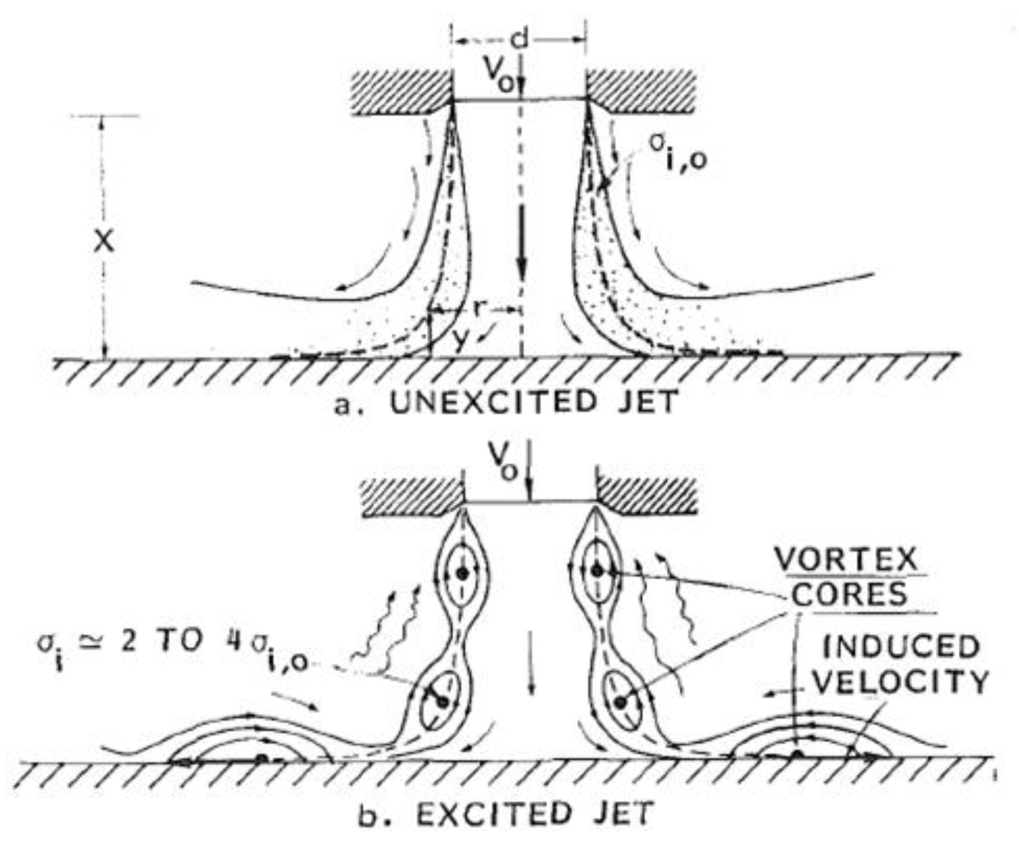
λ, for a given nozzle, liquid, and flow velocity. This can be achieved using a self-resonating jet with discrete vortex rings in its shear layer instead of several small vortices for unexcited jets [
24,
25]. A self-resonating jet can be achieved passively for specific flow rate using a proper nozzle geometry and injection pressure of the liquid. A comparison between an unexcited jet and a structured jet is shown in the
Figure 1.
Johnson et al. [
23,
26] developed an organ-pipe cavitating jet called “CAVIJET” for achieving a structured jet through a passive resonating principle (
Figure 2). The nozzle was shaped such that the hydrodynamic frequency (of the vortex ring) is close to the natural acoustic frequency of the supply system. Therefore, a resonance occurs in the supply chamber that will further excite the jet. Such aero-acoustic coupling is similar to that found in rectangular cavities [
27,
28,
29].
Many experimentations and acoustic analyses of cavitation jets led to the following formula for the estimation of the organ pipe length for a maximum resonance [
10,
30,
31,
32]:
where
L is the organ pipe length;
d is the nozzle outlet diameter;
Sd is the critical Strouhal number;
M is the Mach number;
KN is the model parameter.
It was found that the optimum erosion effect is obtained from the organ-pipe nozzle for
M between 0.08 and 0.09 and
Sd is about 0.3 [
30].
2.3. Rules for the Design of Self-Excited Structured Jets
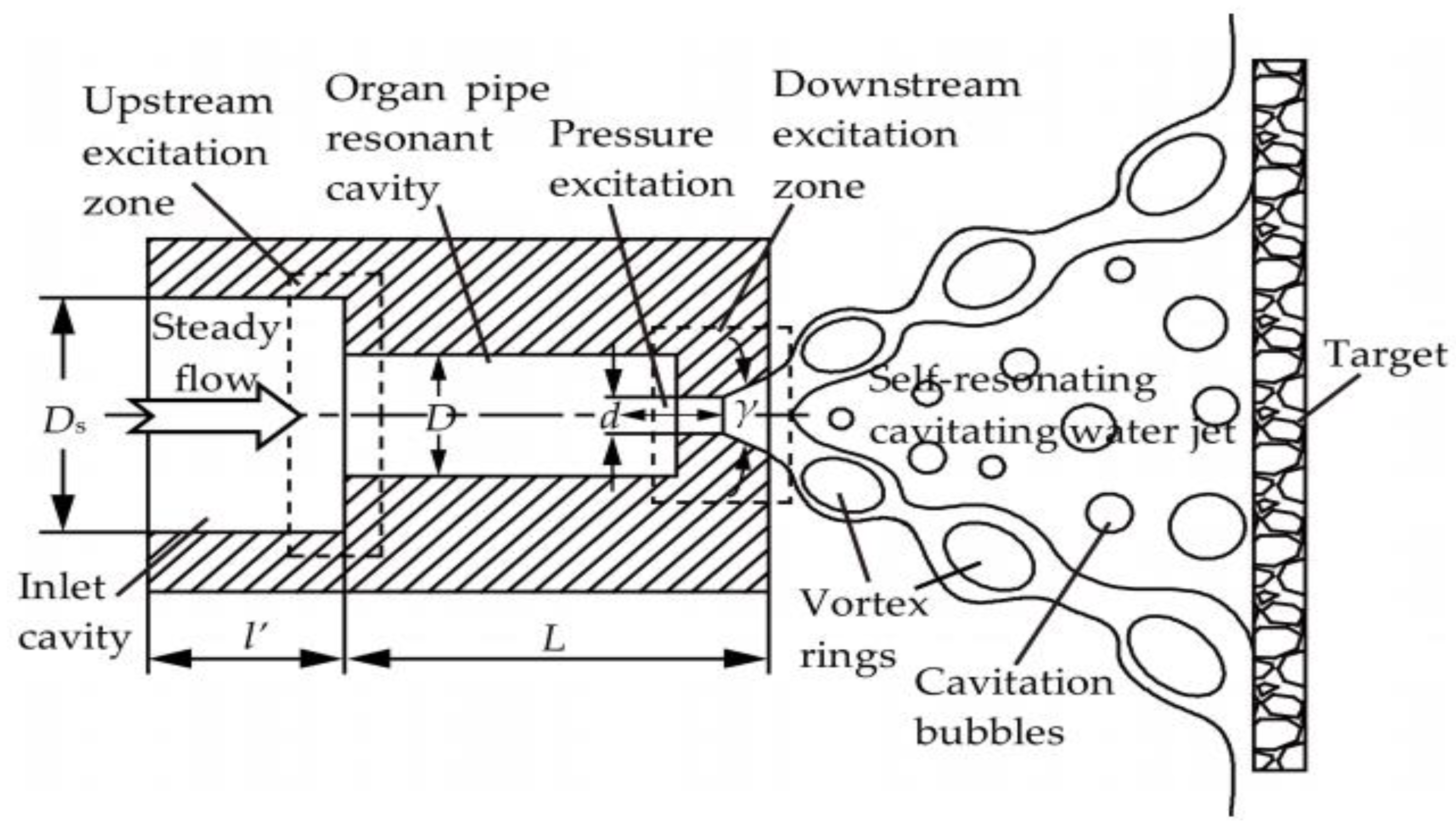
A jet nozzle is fed from a supply system that has a natural acoustic frequency equal to the preferred frequency in the jet turbulent spectrum. The nozzle must be designed to provide the feedback loop to the supply system pressure oscillations associated with the formation of ring vortices in the structured jet. The amplified pressure oscillations generate the resonance in the supply chamber and this resonance excites the jet. This concept is simple but the detailed design of the optimal system is not a trivial process—thus, a quasi-empirical approach was used to produce strongly resonating nozzles.
The organ pipe concept, shown in
Figure 2, can achieve the peak acoustic resonance when a standing wave forms in the “organ-pipe” section. The resonance peak occurs when the frequency of the organ pipe wave is near the critical jet structuring frequency, as given by the nozzle Strouhal number St*, but the exact resonance depends on the contractions at each end of the organ pipe. For example, if both contractions
and
are large, then the first mode resonance will be observed when the sound wavelength in the liquid is approximately equal to 4*Lp. In general, the following approximation was derived (K
N is the mode number):
2.4. Cavitating Jet Flow Dynamics
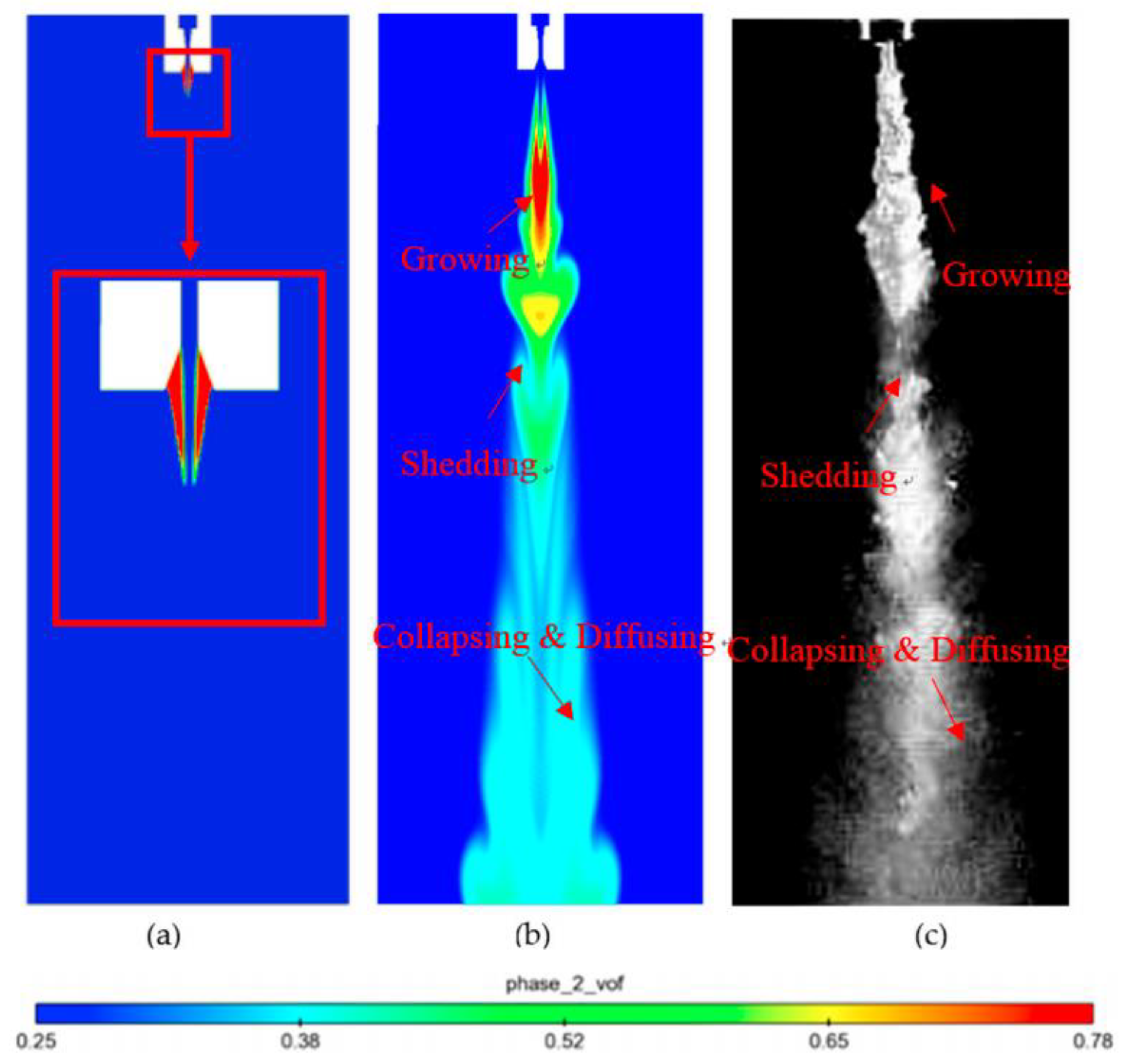
Recently, Yang et al. [
33] compared their numerical predictions of the cavitation cloud in a cavitating jet to their high-speed flow visualizations. They found almost zero vapor volume fraction in the central region of the jet near the nozzle exit and the presence of a ring-type cavitation zone in the high-speed shear layer, around the central zone. They also observed the formation of concentrated vortices similar to those found by other experimental investigations [
34,
35]. These vortices grow as they travel downstream before they shed off from the main cloud, then they collapse and diffuse. The authors distinguished three different zones along the jet, namely, growing, shedding, and collapsing zones (
Figure 3). A good agreement was found between their numerical and experimental results.
It was suggested that the shedding process greatly enhances the performance of the cavitating jet for cleaning applications and rock breaking, since the collapsing of the bubbles happens just after it sheds off the central cloud zone [
36]. The cavitation bubbles with smaller diameter diffuse further downstream and the vapor volume fraction decreases despite the jet expansion.
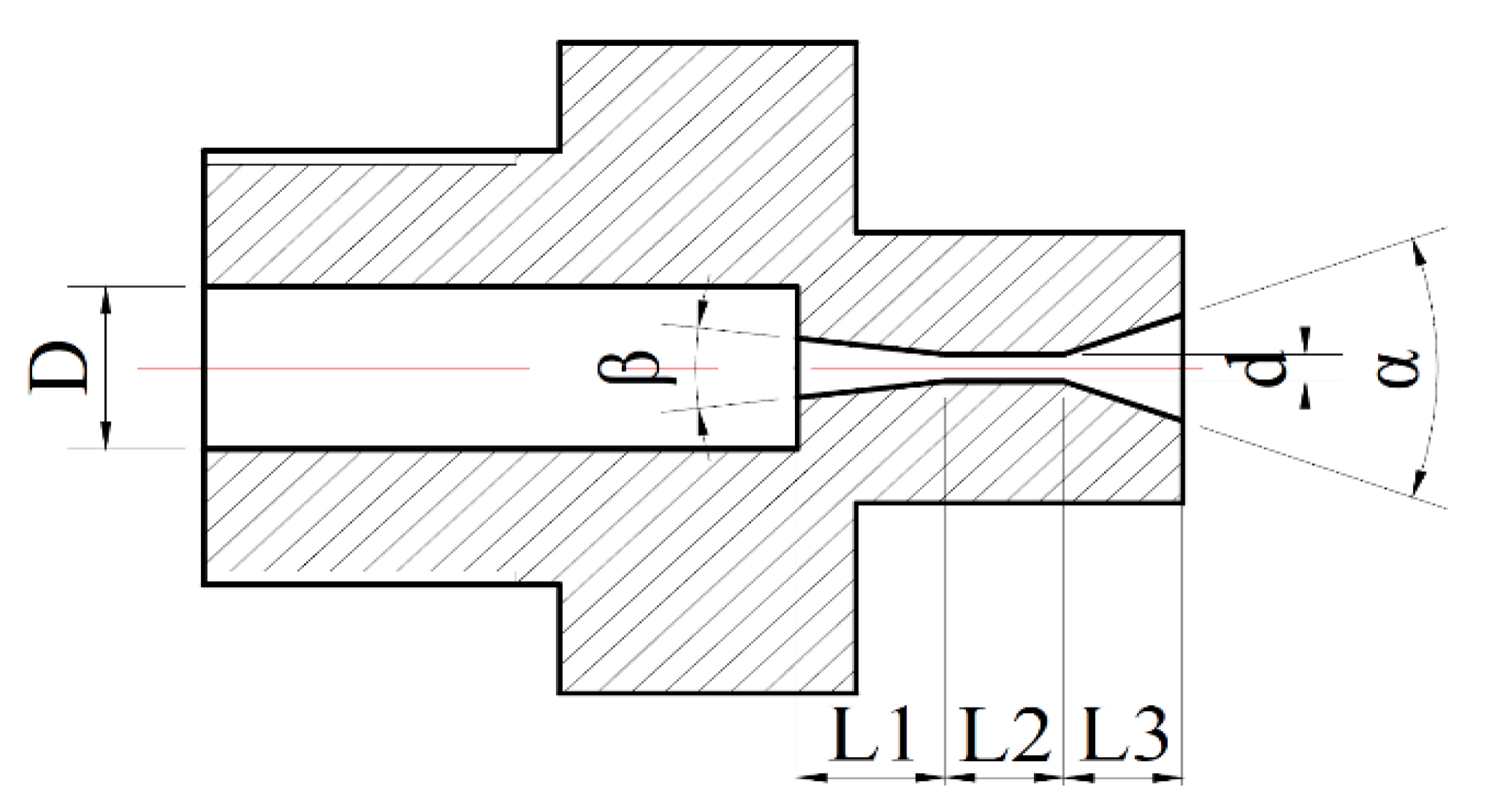
Yang et al. [
33] also studied the effect of the diverging angle of the nozzle exit on the flow dynamics using the RANS RNG k-ε turbulence model. The vapor volume fraction distribution showed (
Figure 4) that the cavitation cloud is larger for a 60° angle than for 40° and 80°. When the divergent angle is reduced (close to 0°), the fluid resistance to flow across the nozzle increases and thus, the jet velocity is reduced when the upstream pressure is kept constant. The shear stress that affects cavitation inception and its development is reduced with smaller velocity gradient.
Using high-speed flow visualizations, Wright et al. [
20] distinguished three regions in the cavitating jet flow: near jet exit, pulse formation, and collapsing zone. The new pulse formation corresponds to the shedding location of Yang et al.’s study [
33]. They also studied the effect of the Reynolds number on the cloud propagation distance and pulsation frequency. They found a 30% increase in the cloud propagation distance when the jet diameter increased from 1.0 to 2.0 mm. The propagation distance also increases with the Reynolds number, while the frequency of the cavitating jet instability decreases when the Reynolds number increases.
Orley et al. [
37] studied the role played by cavitation in the initial stage of a rectangular jet break-up and vaporization using LES simulations that includes a non-condensable gas component in a thermodynamic equilibrium cavitation model. The authors found that the cavitation promotes the jet break-up in the lateral direction. They suggested that, in addition to the Kelvin–Helmholtz instabilities, three main mechanisms are responsible for the jet break-up: (1) turbulent fluctuations due to the cavitation bubbles collapse near the nozzle exit, (2) entrainment of surrounding gas into the jet flow, and (3) collapsing events near the liquid–gas interface of the jet. It was suggested that the collapsing events interface are the main mechanisms in inducing momentum away from the jet axis, which results in the initiation of the jet break-up.
Zhou et al. [
38] studied the flow dynamics, pressure oscillation, and acoustic shock wave characteristics of a self-excited oscillating water jet using Particle Image Velocimetry (PIV) and unsteady pressure measurements. They found a peak pressure 2.5 times larger in the self-excited jet as compared to an unexcited water jet. The PIV results showed a periodic change in the jet velocity along the jet axis and the cavitation cloud goes through the following phases: emergence, expansion, development, compression, redevelopment, compression, and collapse. In addition, the bubble cloud length increases for higher pump pressure. They also found that the acceleration of the acoustic shock wave of the jet is between 0 and 6000 m/s
2.
3. Erosion Mechanism in Cavitating Jets
Hydrodynamic cavitation enhances waterjets efficiency for cleaning and drilling applications. The performance of cavitating jets in those applications is defined by the cavitation erosion they can produce. When cavitation bubbles collapse, the vapor inside the bubble is compressed, generating shock waves. The other important phenomenon which affects material damage is the re-entrant jet: cavitation bubbles become unstable near the wall (located at about one jet diameter distance) and forms a microjet which penetrates into a material [
39]. Shock waves and the re-entrant jet can co-exist during a short time interval when the cavitation bubble is at a maximum expansion near the wall [
40,
41]. When the pressure which is generated by shock waves and microjets exceeds the strength of the material, it fails locally and incubation pits of different size (typically 2–3 hundred of microns in diameter) start to form across the affected surface. This mechanism leads to cavitation erosion and can result in significant material damage [
42,
43,
44,
45].
Special nozzles can be designed to maximize erosion rates. Nozzle geometry in addition to the nozzle material and its surface finish are crucial for a more effective cavitating jet. In most cavitating jets, cavitation starts inside the nozzle and can damage it during the operation. Therefore, the material selection depends on specific application and should be carefully conducted. For drilling applications or radioactive scale cleaning, when the same nozzle should be used for a long duration, it is usually manufactured from titanium alloys that can better resist the cavitation incubation process.
Chahine et al. [
39] discussed the relation between the cavitation impact and the material response when exposed to high intensity cavitation. It is known that in such case, the material is exposed to short duration pressure pulses capable of inducing plastic deformation in the subsurface layers and producing permanent micron-sized deformation pits [
45]. Chahine et al. [
39] illustrated the importance of determining the range of strain rates applicable for a given cavitation impulsive load configuration. The authors confirmed that the consideration of the strain rate effects allows not only a better understanding of the erosion behavior of different materials, but also helps to elaborate more accurate predictive models for long term erosion.
The strain rate of cavitation impulsive loads can be expressed using the following equation:
where Δ
ε is the mean strain caused by an impulsive load, Δ
t is the peak duration,
V is the displacement velocity of the impacted surface, and
l is the length of the plastic zone resulting from an impulsive load.
V and Δ
t can be evaluated experimentally [
46,
47,
48]; Δ
ε and
l are usually estimated from a plastic deformation model of the material.
The authors also showed by comparing the flow stress as a function of the strain rate from different studies that a strain rate of 5 × 10
3 s
−1 corresponds to the transition between low and high strain rate sensitive plastic flow. It was shown that for
< 10
3 s
−1, where the plasticity is controlled by thermally activated processes and the dislocation dynamics, the effect of strain rate is weak. In contrast, for
> 10
3 s
−1, where the plasticity is controlled by viscous drag on dislocation motion (velocity dependent), the effect of strain rate is more pronounced [
49,
50].
3.1. Effect of Nozzle Surface Roughness
It should be noted that there is an optimum finish that should be applied to the inner surface of the nozzle to achieve an optimal erosion regime. It was shown [
44] that an extremely smooth surface reduces erosion rates because less cavitation bubbles are generated inside the nozzle; an excessive roughness can lead to significant energy losses, distorted jet structure, and as a result, a reduced erosion. Li et al. [
44] studied six organ-pipe cavitating nozzles with different surface roughness (0.8, 1.6, 3.2, 6.3, 12.5, and 24 μm). The specific energy consumption and mass loss for different inlet pressures and target distances were measured. All experiments were conducted at 20 °C using tap water. It was shown that the best erosion effect occurred for both inlet pressures of 10 and 15 MPa and a surface roughness of 12.5 μm at the optimal target distance of 50 mm, whereas for inlet pressures of 20 and 25 MPa, the optimal roughness was 6.3 μm and the optimal distance to target increased to 60 mm.
3.2. Effect of Standoff Distance
In addition to geometrical parameters of the cavitating jet nozzle, the target standoff distance and the attack angle are always considered in cleaning, peening, and cutting applications. Yamauchi et al. [
51] considered different standoff distances for erosion experiments with aluminum plates. Three types of nozzles were used in their study: conical, cylindrical, and venturi (horn) types, made of stainless steel SUS 304. All targets were placed normal to the jet nozzle, 30 MPa was used as the working pressure, and the duration of the experiment was 5 min. Three regions were defined for the target location, Region I: x/D = 5 (where x is the distance from nozzle exit to the target and D is nozzle diameter), Region II: x/D = 15, Region III: x/D = 100. The mass loss of the aluminum plate was recorded after the experiments. It was shown that the maximum erosion for all nozzles was achieved around x/D = 15 (
Figure 4). It was thus suggested that Region II is optimal for cutting and Region III is optimal for peening. It can also be seen from
Figure 5 that the erosion efficiency strongly depends on the nozzle geometry. For the same operating conditions, the cylindrical type resulted in significantly higher erosion rates as compared to the two other nozzles used in the experiments.
Figure 4.
Mass loss vs. Standoff distance [
51].
Figure 4.
Mass loss vs. Standoff distance [
51].
In [
52,
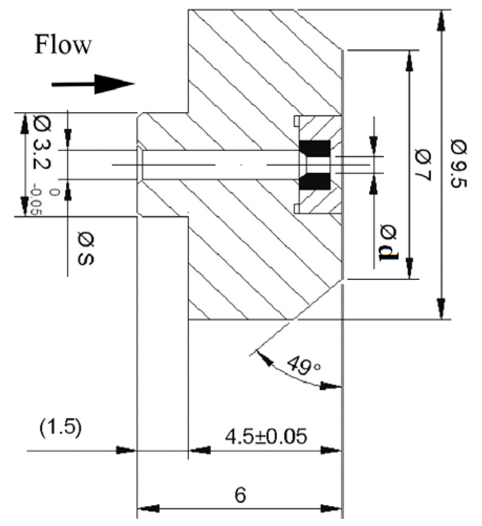
53], the effect of different geometrical parameters on the cavitation erosion was experimentally studied using copper samples exposed to a high-speed submerged cavitating jet for various durations. Erosion rates and eroded areas were discussed. Influences of the dimensionless standoff distance x/d (x is the distance to the target and d is the nozzle outlet diameter), the aspect ratio L/d (L is the nozzle length) and the angle of attack were investigated. Convergent nozzles were used for these experiments and the operating regimes are shown in
Table 1. The jet nozzle geometry is shown along with
Table 1 (
Figure 5). The duration of each experiment was 30 min. Since the nozzles could not be moved, and in order to accommodate the ASTM G134 [
54], increasing the specimen’s thickness was used to set the standoff distance.
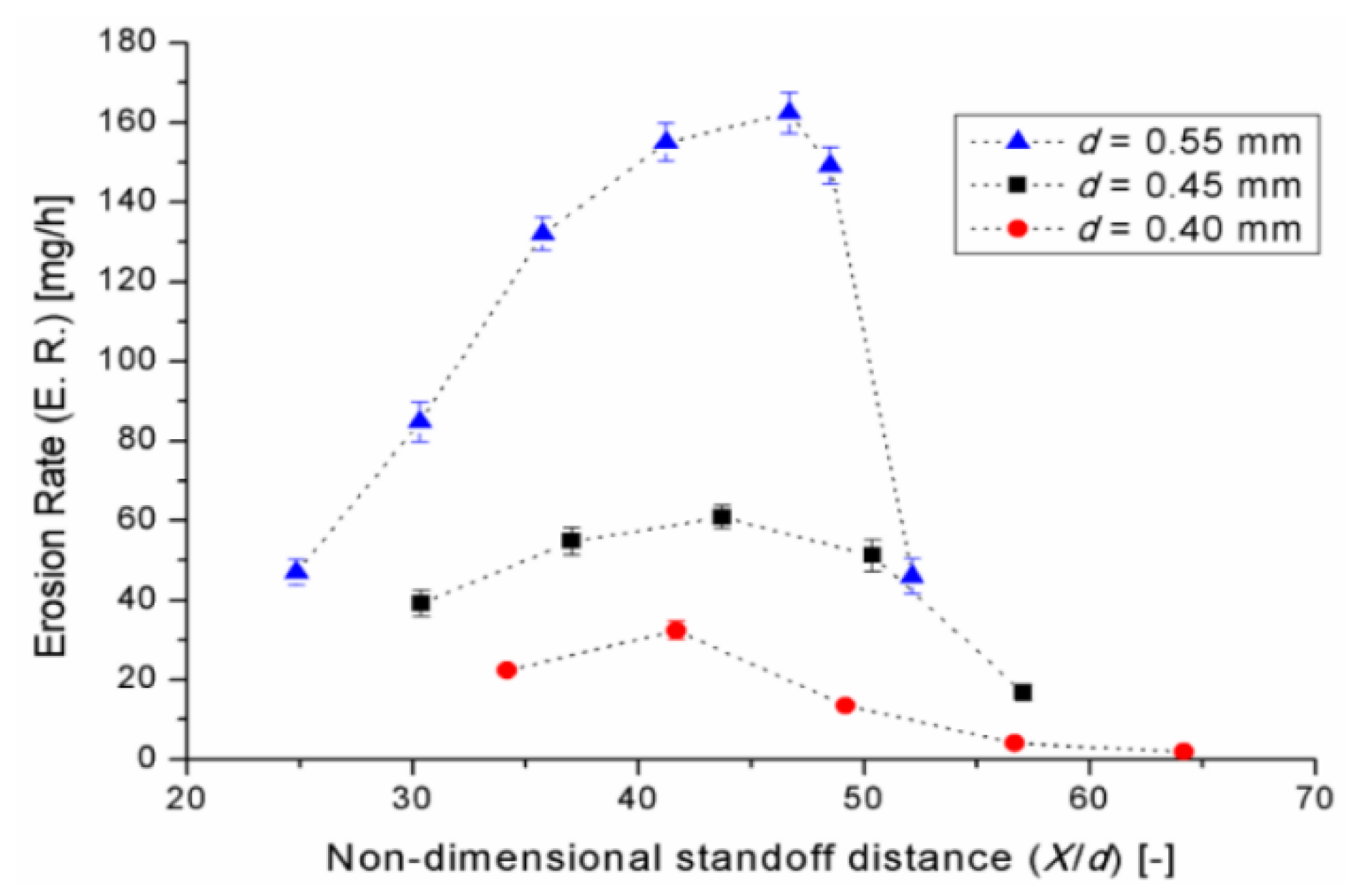
It can be seen from
Figure 6 that under the same operating conditions, the erosion rate is significantly affected by standoff distance and nozzle diameter. Therefore, the optimum position for maximum damage can be found and occurs close to the nozzle which is completely different in the case of conventional jets, where the position of the target is much less critical and can be much farther from the nozzle outlet. This can be explained by the dynamics of cavitation bubbles. Vickers and Houlston [
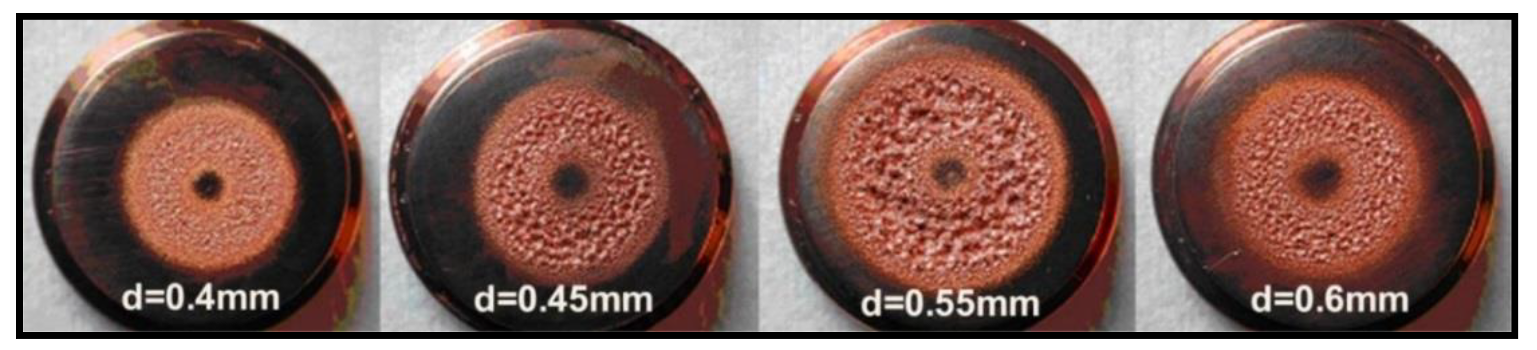
55] developed a model of a cavitating jet and showed that the optimal distance is related to a point in the flow where the bubble has expanded to a maximum size prior to its collapse. The authors also showed that the high speed of cavitation bubbles growth and the need for these bubbles to be at a maximum size prior to collapse determine the critical standoff distance for cavitating jets and therefore, the position for the maximum damage. The typical jet erosion pattern for different nozzle diameters is shown in
Figure 7. It was also shown that the optimal standoff distance was a function of the cavitation number and that the cavitation efficiency increases with the upstream pressure and has a peak that changes with the downstream pressure for a cavitation number of 0.014.
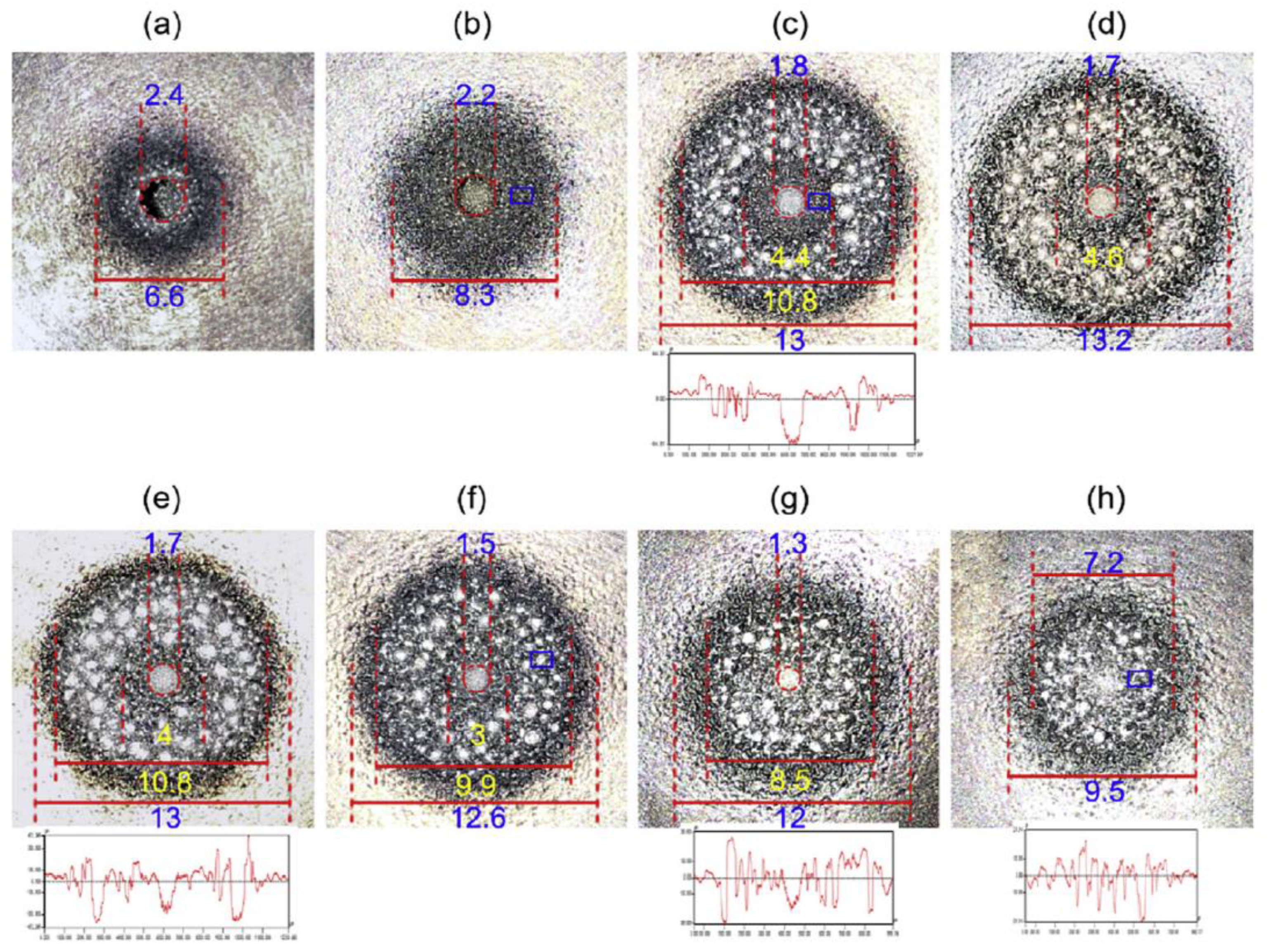
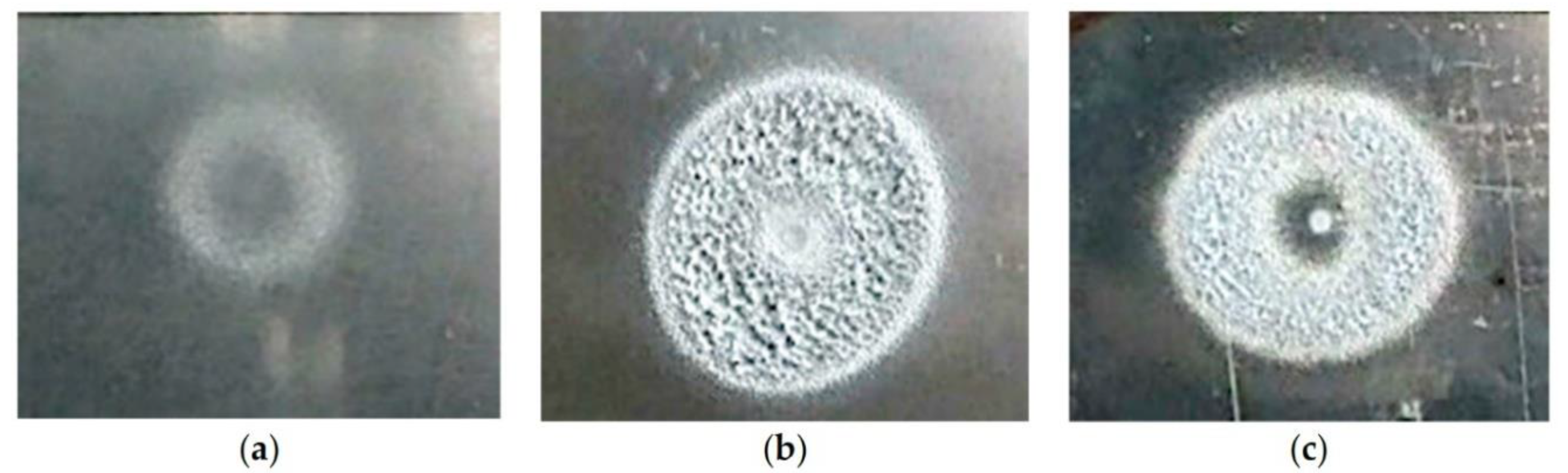
In order to investigate the relationship between cavitation cloud and cavitation erosion, Peng et al. [
56] conducted simultaneous high-speed flow visualizations and erosion tests. Proper Orthogonal Decomposition (POD) was used to analyze the spatiotemporal distributions of the cavitation cloud. In addition, both macroscopic and microscopic methods were implemented to study the morphology of the eroded specimen. The POD analysis showed that the low-order POD modes are organized in pairs, which confirms the periodicity of the cavitation phenomenon. Both macroscopic (
Figure 8) and microscopic (
Figure 9) pictures showed that the damage pattern changes with the non-dimensional standoff distance (NSD). Under small NSD (
Figure 8a,b), the central hole eroded by high-speed water jet is the dominant contributor for mass loss and the cavitation bubbles do not have enough time to grow before they reach the impinging plate. As NSD increases, cavitation erosion in the form of hemispheric pits is observed, and typical ring-shape distribution of cavitation pits is obtained (
Figure 8c,d). The optimal NSD of 91.7 (
Figure 8d) is characterized by a balance between bubble concentration and collapse intensity and cavitation pits much deeper than the central hole. As NSD further increases (
Figure 8e–h), both the pits size and the erosion ring diameter decreases.
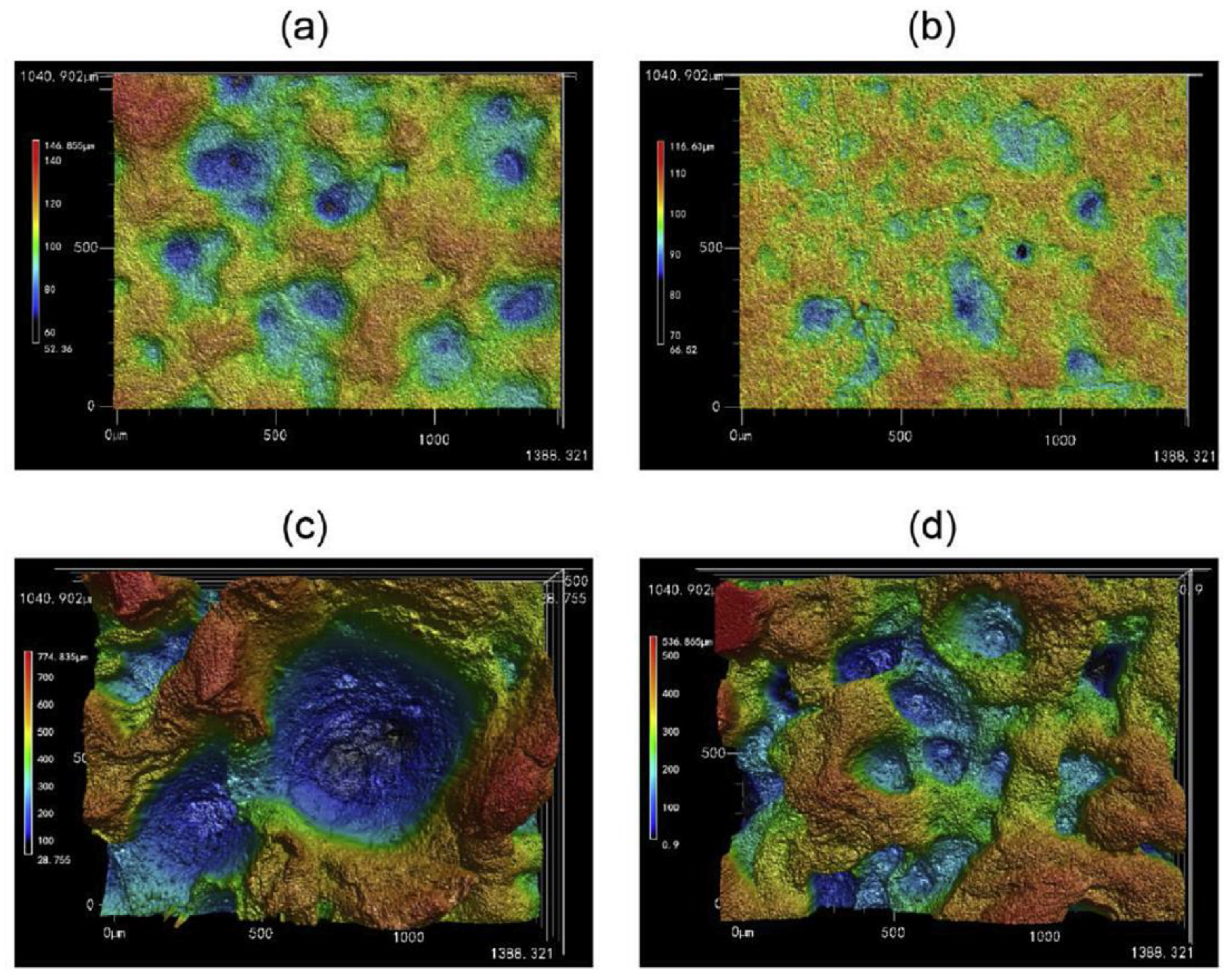
From a microscopic point of view (
Figure 9), the aggravation of cavitation erosion is the jointed results of the growth of single cavitation pits and the connection of adjacent pits. The ridges and protrusions are preferable sites for bubble collapse.
It should also be noted that NSD decreases with the increase in jet nozzle diameter. This can explain the difference between the NSD values of the studies presented above.
3.3. Effect of Angle of Attack
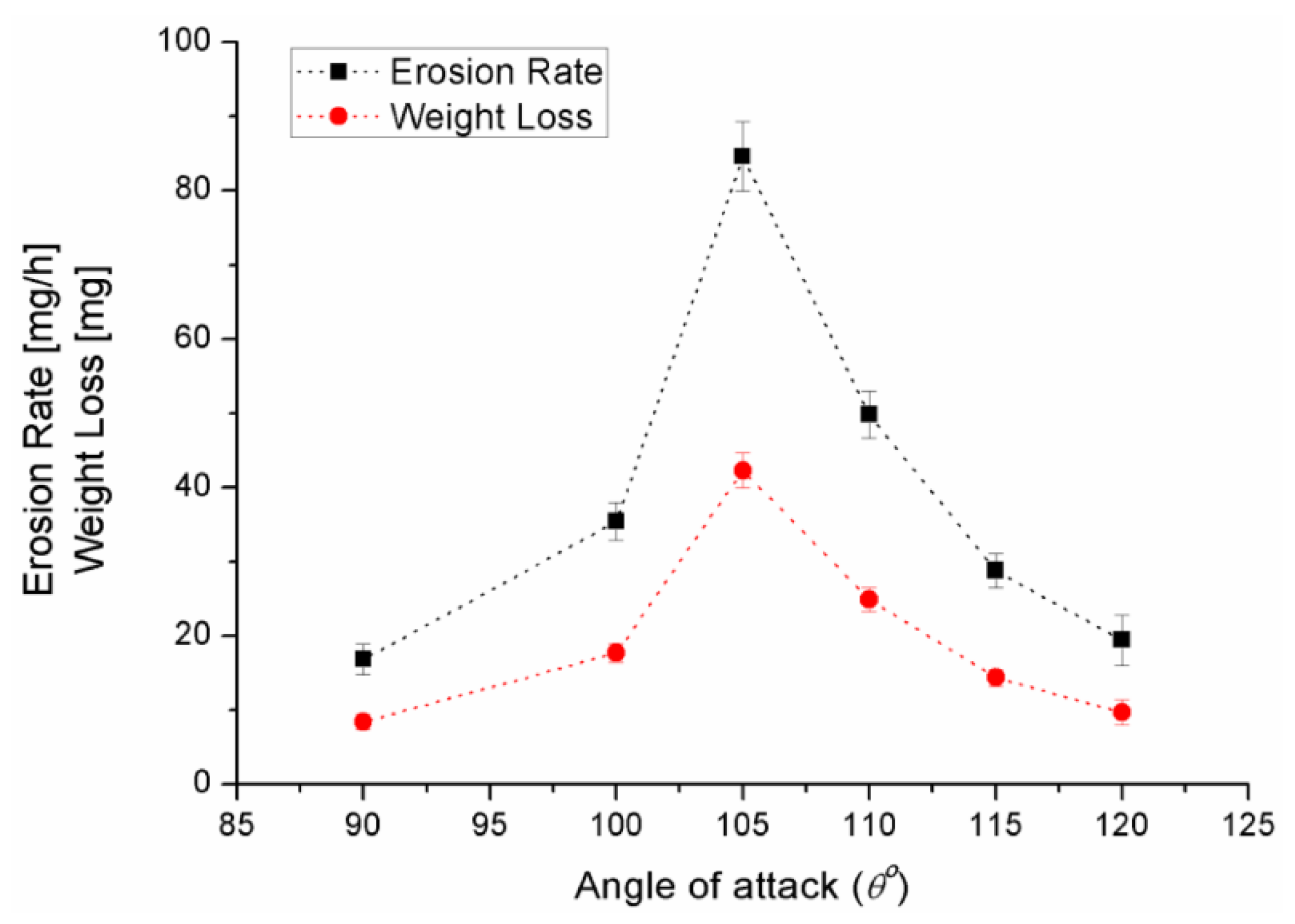
For hydrodynamic cleaning applications, it is important to consider the angle of attack of the nozzle on the target surface which depends on the industrial application. For example, the optimal nozzle angle for cleaning the concrete plug, which occupies full pipe diameter, is different from the angle for cleaning the thin layer of scale on the walls.
A series of tests were performed in order to investigate the influence of the angle of attack on the behavior of the cavitating jets and on the erosion process in [
52]. The jet impact angle was defined as the angle between the axis of the nozzle and the target surface. The same type of nozzle was used for these experiments. Experimental conditions for the attack angle tests were defined as follows: P
1 = 14.6 ± 0.1 MPa, P
2 = 0.321 ± 0.001 Mpa, V = 113.6 ± 0.5 m/s, σ = 0.00342 ± 0.001, T = 25 °C. The experimental results are presented in
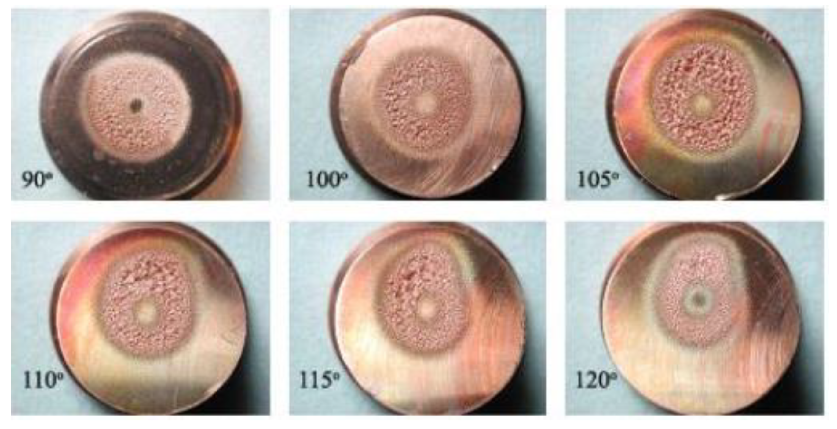
Figure 10. It can be seen that the angle of attack significantly affects the erosion rate and the mass loss. Due to the inclination, the distance between the nozzle and the target varied along the sample. In the upper part of the sample, the longer distance allowed more bubbles to be produced before they collapsed along the surface. Therefore, most of the bubbles will collapse on the upper region of the target (
Figure 11), leading to more pronounced damage in that region. The optimal angle that results in a higher erosion rate could be related to the influence on the two most important cavitation erosion parameters: the shape of the bubbles and the pressure distribution around them.
3.4. Effect of Exit Velocity
It was shown [
53] that as the cavitation number decreases or as the exit-jet velocity increases, the mass loss, the erosion rate, and the eroded area increase. The strong relationship between the jet exit velocity and the erosion rates was also stated in [
39]. The distribution of cavitation bubbles along the jet path and along its radial cross-section is also a function of many parameters, such as the upstream and downstream pressures, the nozzle diameter, the standoff distance, the nozzle geometry, and the flow pattern.
3.5. Effect of Fluid Temperature
The other important parameters which affect cavitation erosion are fluid properties and particularly, its temperature. The temperature effect on cavitation was studied in [
57,
58,
59,
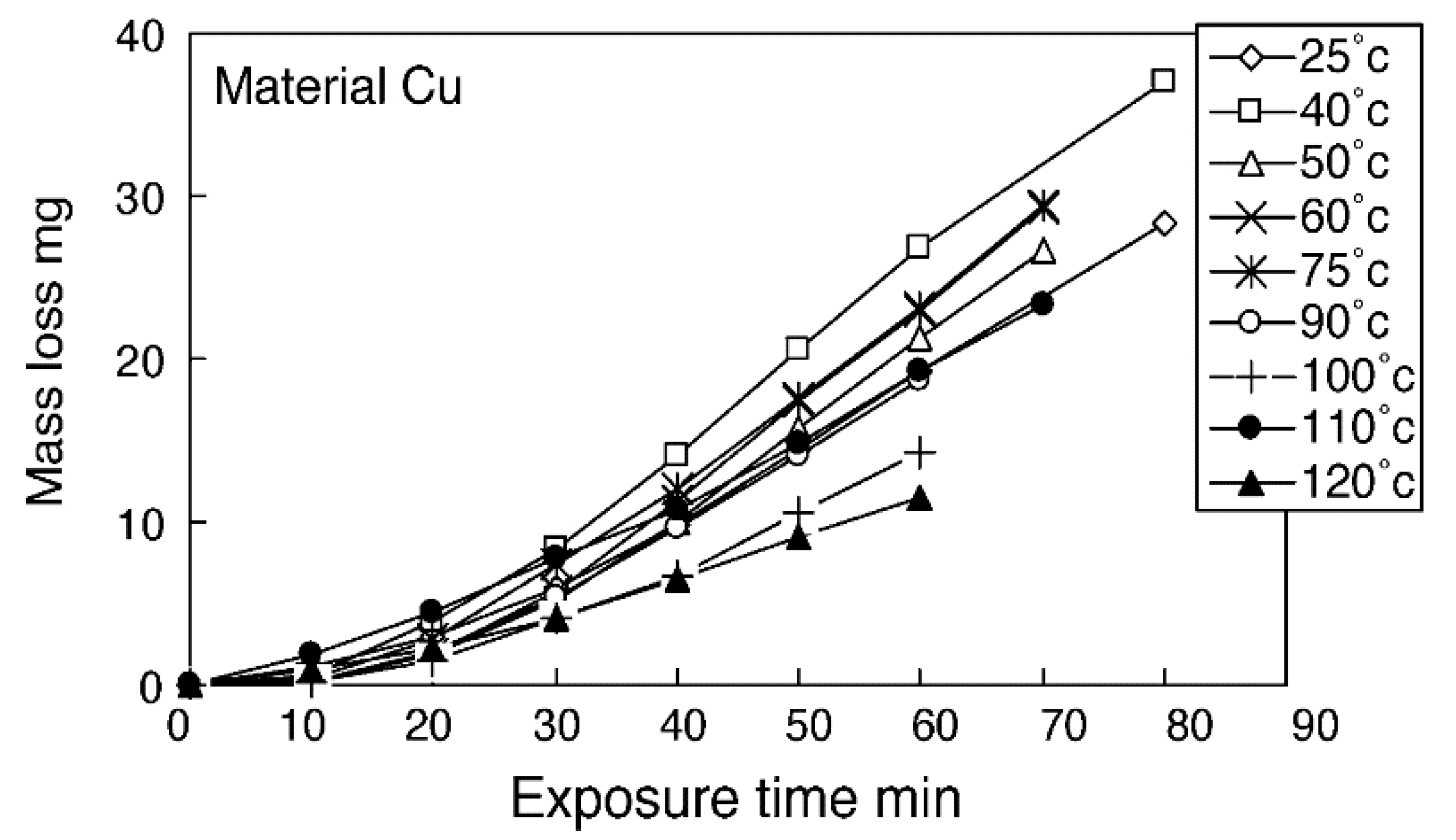
60]. Hattori et al. [
61] found that the erosion rate increases with the water temperature and reaches a peak before decreasing. The peak is about the average of the freezing and boiling relative temperatures. The erosion rate increased by 1% per 1 °C between 5 and 45 °C of relative temperatures, and decreased by 2% per 1 °C between 45 and 80 °C. The experiments were conducted at an upstream pressure of 17.4 MPa and a cavitation number
σ = 0.015. The mass loss vs. exposure time at different temperatures is shown in
Figure 12 for pure copper samples. It can be seen that for all temperatures, the incubation period is about 15–20 min and the maximum erosion rate (local slope) is achieved at 40 °C.
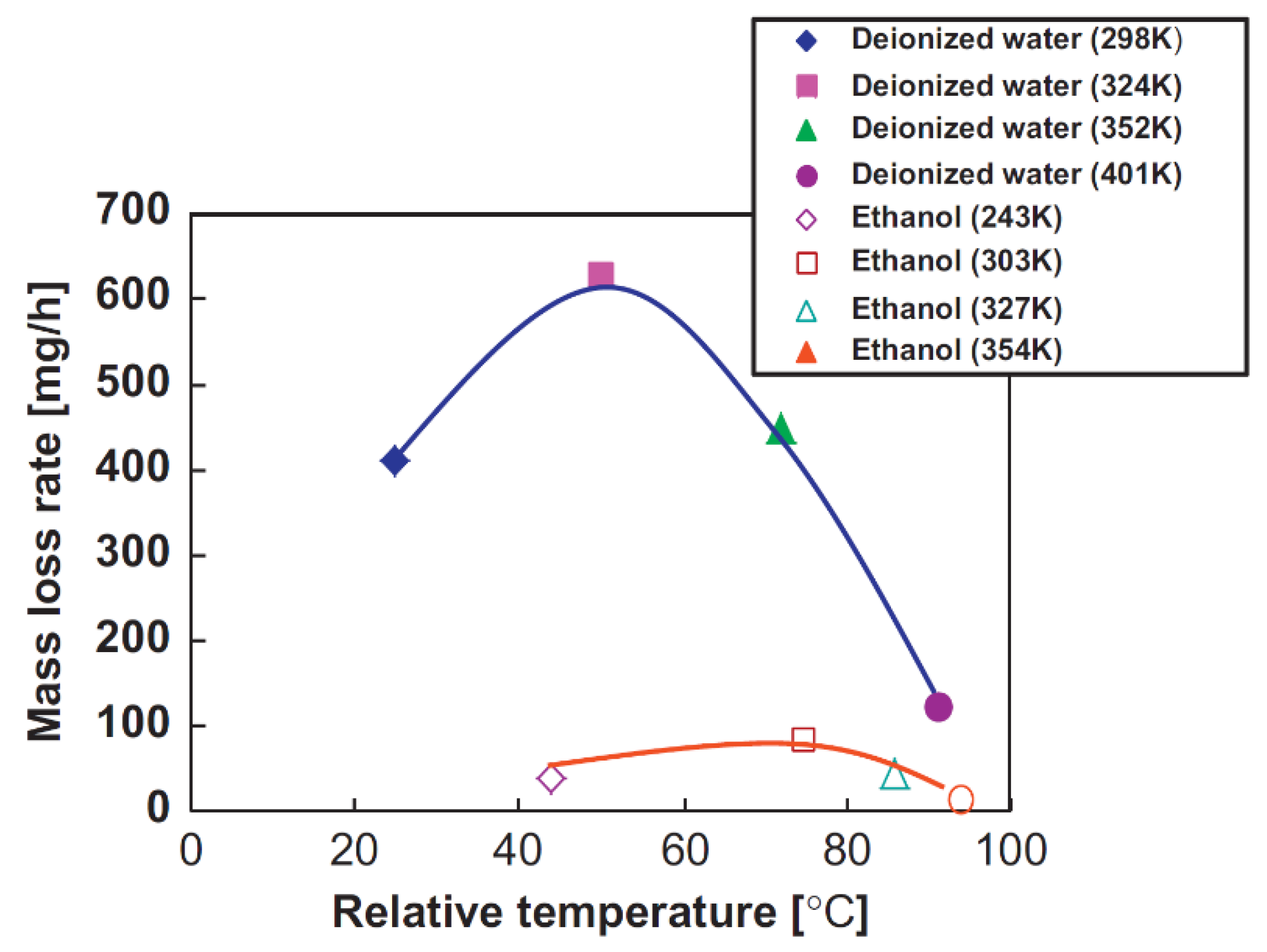
Similar results were found by Hattori et al. [
62] using deionized water. In this study, cavitation erosion tests were conducted using silver plated coatings at a constant cavitation number of 0.03. The results for mass loss rate are shown in
Figure 13. Relative temperature in this figure is equal to (test temperature-melting point)/(boiling point-melting point). It can be seen that for ethanol, the temperature that corresponds to the maximum mass loss rate is higher than that of deionized water.
It is more complicated to generate cavitation at low temperatures (close to 0 °C for water) but the bubble implosion is much more violent. The quantity of cavitation bubbles increases with temperature, but the implosion energy decreases. The decrease in the implosion at elevated temperature (close to 100 °C for water) happens because of the bubbles’ inability to trap vapor inside them, their volume grows and they implode. An ideal balance between quantity of the cavitation bubbles and implosion power is achieved at 40–50 °C [
63].
A summary of the jet and flow parameters for different studies is presented in
Table 2.
4. Industrial Applications of Cavitating Jets
4.1. Jet Hydrodynamics for Cleaning Applications
Ji et al. [
67] introduced a new method based on the cavitation effect to assist soft abrasive flow (SAF) processing. The fluid used for high-speed soft abrasive flow has a low viscosity. The conventional SAF processing method is widely used due to its ability to avoid material damage. However, these SAF methods suffer from long polishing times and low efficiency. To address these issues, it was proposed to add a cavitation effect to assist the soft abrasive flow polishing. It was shown that the SAF with cavitation has a significantly shorter processing time and better polishing quality.
There are two types of nozzles which are applied in hydrodynamic cleaning industry. The first type utilizes the maximum technologically possible discharge coefficient. In this case, the jet’s destructive property is mostly characterized by hydrodynamic jet impact. Usually, such nozzle design is close to a de Laval nozzle. The second type of nozzle utilizes the cavitation effect and minimizes the discharge coefficient. This can be achieved by manufacturing and installation of impact sharp edges inside the nozzle, which generate more cavitation bubbles.
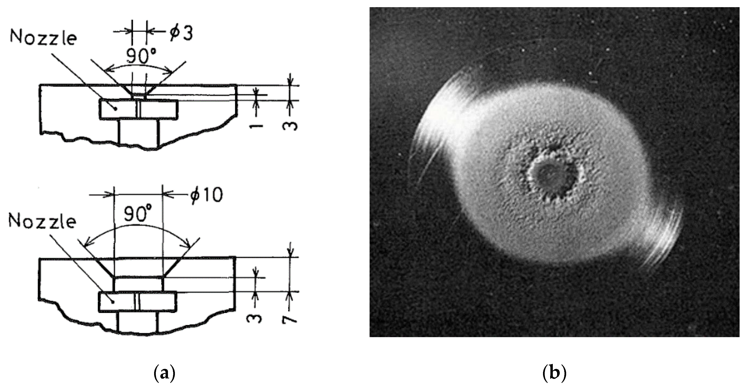
Yang et al. [
33] performed erosion tests using nozzles of type one (
Figure 14). The discharge coefficient was around 0.8. Aluminum plates were used in these experiments, with an exposure time of 60 min, an upstream pressure of 20 MPa, and a distance to the target of 66 mm. Other parameters are shown in
Table 3 and
Figure 14. Erosion results for three nozzles’ configurations are shown in
Figure 15, which illustrates that the 60° nozzle has the best erosion efficiency.
Yamaguchi and Shimizu [
68] used the nozzles of the second type. The nozzle used in this study is shown in
Figure 16a. The discharge coefficient in this case was 0.6 which is lower than in [
33]. Most of the experiments were conducted at 9.9 MPa inside the system, and the ambient pressure was varied from 0.14 to 0.40 MPa. Circular plates of aluminum alloy (A5056BD) were used in erosion experiments. The erosion pattern for “nozzle B” is shown in
Figure 16b. Impinging cavitation clouds collapse on the target causing ring damage on the specimen. When the standoff distance is short (10 mm; Yamaguchi and Shimizu [
68]), a deeply eroded ring-like valley is also formed in the region near the center.
In [
33], the mass loss was measured at the end of each experiment for various stand-off distances. High water-based fluid of chemical solution type (HWBF) and tap water were used as test liquids. For “nozzle A”, the mass loss for ambient pressures of 0.14, 0.20, 0.30, and 0.40 MPa had maximum values at standoff distances of 25–27.5, 20–22.5, 20, and 17.5 mm, respectively. For ambient pressures of 0.4 and 0.20 MPa, the mass losses had local maximums at 12.5 and 10 mm, respectively. The maximum mass loss for “nozzle A” was 150 mg after 2 h of exposure to the cavitating jet.
From the experiments conducted at a standoff distance of 10–22.5 mm using “nozzle B”, the mass loss had a maximum at a standoff distance of 20 mm and a local maximum at 12.5 mm for an ambient pressure of 0.14 MPa. When the downstream pressure is equal to or larger than 0.20 MPa, the mass loss had a maximum at a standoff distance of 10 mm. The maximum mass loss for “nozzle B” was 70 mg after 2 h of exposure to the cavitating jet.
It was also shown that, in general, the mass loss with tap water was smaller than that in HWBF with the same operating conditions. The effect of high weight polymer on cavitation erosion was also described by authors. Ashworth and Proctor [
69] reported that the erosion rates increased when replacing water with polyacrylamide. In [
70], it was shown that underwater jet cutting was significantly improved by polymer additions to the jet fluid. In [
71], it was observed that the cavitation bubbles in the drag reducing polymer solution appeared larger than those in pure water. It was suggested that the larger bubble size in the polymer solution could be the reason for increased cavitation erosion rates in comparison with water.
4.2. CAVIJET Performance for Well Drilling
The structured flow issuing from cavitating jets presents several advantages relative to the conventional nozzles used in deep-hole drilling; namely, greater ability to erode or otherwise weaken the rock, and an improved mechanism for removing chips from the hole bottom [
18].
Cavitating jets have been used in a number of mechanical devices for drilling, such as tunneling and mining. Therefore, continuous development was being conducted on the flow dynamics of cavitating jets in order to use the hydraulic energy more efficiently and thus, enhance the drilling performance [
72]. It should be noted that pumps that generate pressures up to the 60,000 psi are used in the industry. Process of drilling can be accompanied with roller or diamond cutting surfaces and more pressures are required for these applications.
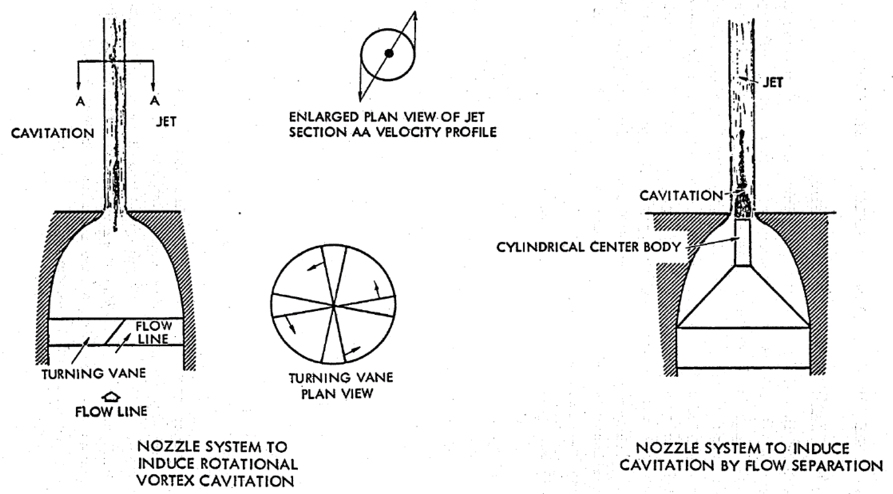
CAVIJET is a cavitating jet that has been designed with better drilling performance for higher pressure and temperature holding systems. A typical configuration of CAVIJET nozzle design and its working apparatus is shown in
Figure 17 [
73]. It was found that the “centre-body” nozzle configuration is suitable for in-air experimentation, whereas “Turning Vane” or the plain nozzle designs (without vanes or center-body) can be used for deep-hole drilling on submerged surfaces [
73]. Different nozzle systems are available for the induction of vortex cavitation and for flow separation while cavitation occurs. A swinging shutter plate was placed between the rock surface and the nozzle to control the exposure time of drilling in the given apparatus. Exposure time was counted to be between 5 and 60 s and it mainly depended upon the type of rock.
The experimental results of Conn and Radtke [
73], at both atmospheric and elevated ambient pressures up to 21 MPa, have shown that the CAVIJET will perform effectively under down-hole pressure conditions. They also found that the optimum standoff distance for CAVIJET drilling decreases from about 14 nozzle diameters in the atmospheric pressure tests to about 2 nozzle diameters under a 3000 psi (21 MPa) ambient pressure. These test results have demonstrated the effectiveness of the CAVIJET method up to an equivalent borehole depth of 1770 m if using a fluid density of 1200 kg/m
3.
4.3. Rock-Cutting Ability of Self-Resonating Jets
A structured jet can be achieved passively for specific flow rate using a proper nozzle geometry and injection pressure. The self-resonating jet, developed by Johnson et al. [
23,
26], for achieving structured jet flow through a passive resonating principle, was shaped such that the hydrodynamic frequency (of the vortex ring) is close to the natural acoustic frequency of the supply system (organ pipe). A High-Pressure Cell (HPC) was built by Johnson et al. [
26] to experimentally investigate the behavior of submerged self-resonating cavitating jets with a pressure of up to 20.7 MPa inside the test chamber. The high-pressure fluid for this cell was provided using a plunger pump. Flow visualization, anemometry, and unsteady pressure measurements were conducted for different flow regimes. Different critical Strouhal numbers of the resonating jet were obtained using different diameter to length ratios (d/L; d is the jet exit diameter and L is the length of the organ pipe). It was found that the maximum modulation amplitude (
u′/
V) decreases as the nozzle features are altered in order to raise the critical Strouhal number. This result is explained by the reduction in the spacing between the vortices when the Strouhal number increases. Thus, the circulation strength of each vortex is lower, and the maximum value of
u′/
V in the jet decreases.
The authors [
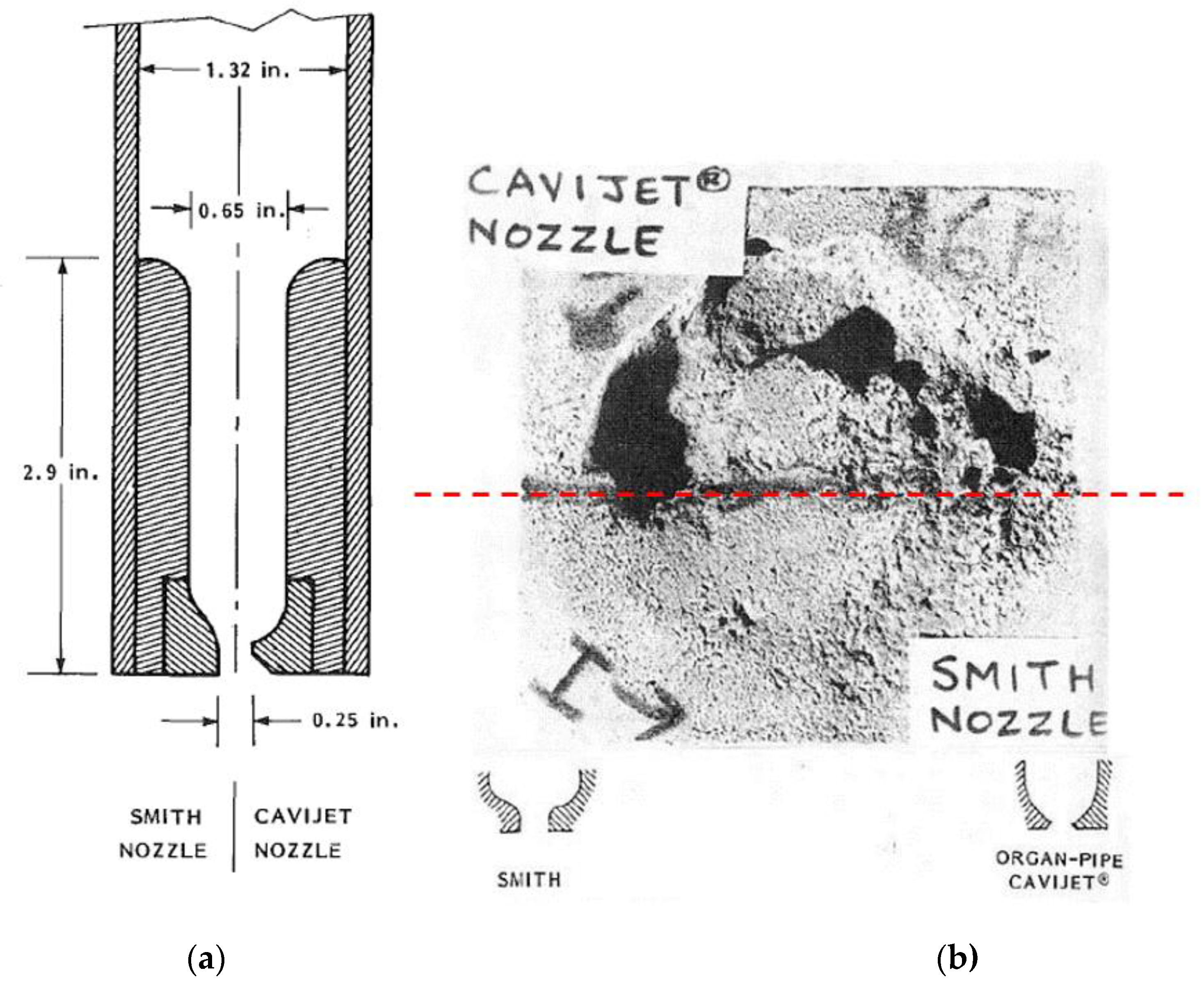
26] also carried out several tests to compare the rock cutting ability of a conventional and a structured cavitating jet. A typical rock-cutting comparison is shown in
Figure 18b between a CAVIJET and a conventional Smith nozzle supplied for use in a roller-cone deep-hole bit.
Figure 18a shows the dimensions of an organ pipe configuration used to feed either a standard Smith Tool nozzle shape or a CAVIJET nozzle. A top-view of one face of a 6-in. cube specimen of Indiana limestone is shown in
Figure 18b. To allow a half-circle cut to be made by each nozzle, one half of the rock face was protected by a metal plate. It is found that under the same operating conditions, the mean slot depth cut by the organ pipe CAVIJET was 4.3 times deeper than that cut by the Smith nozzle.
4.4. Well Drilling Test Using Cavitating Jets
Song et al. [
10] investigate the performance of well drilling for the construction of salt caverns using cavitating jets; drilling performance was compared to a conventional mining method. Their field test indicates that rapid solution mining technology with self-resonating cavitating jets can significantly speed up the construction at the pocket stage of cavern development.
The experimental results showed that the pressure amplitude peak occurs at a distance of 5–13 times the nozzle outlet diameter. They also found that under the same operating conditions, the cutting potential of self-resonating cavitating jets is twice that of conventional jets.
The field test showed that the use of self-resonating cavitating jets would increase the salt production rate at least by two-fold as compared to the conventional method.
4.5. Bitumen Separation Using Cavitating Jets
In some applications such as bitumen separation based on cavitation jets [
7,
8], it is important to understand the behavior of the cavitation jet in multiphase media.
Oil sands, also known as tar sands, are unconventional heavy oil deposits. They are composed of very heavy crude oil, water, clay stones, and other minerals. As a part of the separation process, oil sand is mixed with water forming multiphase slurry, then the slurry is pumped through hydrotransport which consists of a system of long pipelines and large slurry pumps in order to breakdown the lumps of oil sands. The hydrotransport line is several kilometers long and the turbulent flow in the pipeline is found to be very effective in breaking down the lumps of oil sands, improving the recovery of bitumen in the main extraction plant. One of the disadvantages of hydrotransport is the high erosion rates since the oil sand is very abrasive. Bukharin et al. [
65,
66] suggested replacing hydrotransport with cavitation jet vessels. It was shown that cavitating jets produced typical cavitation erosion on aluminum plates and had an ability to separate bitumen from oil sand. In their recent study, Bukharin et al. [
8] demonstrated that self-resonating nozzle jet presents greater performance as compared to both conventional nozzles and conventional nozzles with flow control in the bitumen-oil separation process.
4.6. Borehole Cavitating Jet Hydraulic for Oil-Shale Mining
Oil-shale has been widely used as a supplement to conventional energy resources. For deep and low-grade oil-shale mining, borehole hydraulic mining is considered the most suitable technology [
74,
75,
76,
77,
78,
79]. During this process, high-pressure jets are used to break the oil shale [
80]. Therefore, the high performance of the water jet is critical for the overall success of this drilling process [
80,
81,
82]. This method presents many advantages such as the reliability and simplicity of operation. In addition, it does not require removing the overlying strata.
Wen et al. [
80] used the organ pipe nozzle shown in
Figure 19. It is a typical self-resonating cavitating jet nozzle where a standing wave develops in the cavity of the nozzle and excites the eddies of the jet shear layer resulting in large-scale vortex rings. The high kinetic energy of the separated vortex rings can enhance the cavitation erosion effect of the jet [
31,
32]. Wen et al. [
80] found that for the non-submerged condition, the performance of the self-excited oscillating pulsed jet nozzle is always greater than the straight cone nozzle. They also found that the striking force produced by the self-excited oscillating jet decreases when the distance from the jet exit increases. For the cone nozzle, the striking force increases with the jet distance then it decreases with further increase in the jet distance.
5. Conclusions
In this paper, a literature review on the erosion mechanism and the flow dynamics in cavitating jets is provided. The focus was on both experimental and numerical investigations in cavitating jets and their industrial applications.
It was shown by many authors that the erosion potential of cavitating jets can be enhanced using specific jet nozzle geometries that result in self-excited flow regimes and thus, the amplification of the pressure amplitude at the impinging wall. It was illustrated that the incipient cavitation numbers for the self-excited structured jet can be two to six times higher than with a conventional jet.
It was also shown that the nozzle material and its surface finish in addition to the standoff distance, the jet angle, the fluid temperature, and the flow regime play a crucial role for effective cavitating jet performance.
When selecting a self-resonating nozzle jet, both the flow regime and the nozzle geometry should be considered for a proper nozzle design. The critical Strouhal number can be varied by changing the nozzle geometry, so the circulation strength of the large-scale vortices is maximized.
When properly designed, self-resonating jets showed their superior performance as compared to standard jet nozzles for different industrial applications, ranging from cleaning applications to rock cutting, oil-shale mining, and bitumen separation.
The main challenge facing the implementation of the cavitating jets in the drilling industry is the shorter jet core, resulting in a pressure amplitude peak that occurs at a few jet diameter downstream from the jet exit. Therefore, careful design of these jets should be conducted depending on the specific drilling configuration, and further development of the nozzle geometries would be of high benefit for their successful industrial implementation.


