Article

Hydrodynamic and Energy Capture Properties of a Cylindrical Triboelectric Nanogenerator for Ocean Buoy

1
College of Shipbuilding Engineering, Harbin Engineering University, Harbin 150001, China
2
Yantai Research Institute and Graduate School, Harbin Engineering University, Yantai 265500, China
3
College of Mechanical and Electrical Engineering, Harbin Engineering University, Harbin 150001, China
*
Author to whom correspondence should be addressed.
Appl. Sci. 2021, 11(7), 3076; https://doi.org/10.3390/app11073076
Submission received: 6 February 2021 / Revised: 5 March 2021 / Accepted: 26 March 2021 / Published: 30 March 2021
(This article belongs to the Section Energy Science and Technology)

Abstract

:
It is rather challenging to collect ocean wave energy at high efficiency because of its ultra-low frequencies and variable amplitudes. Triboelectric Nanogenerator (TENG) technology is more suitable for harvesting low-frequency than electromagnetic power generation technology. In this work, we designed a built-in cylindrical Triboelectric Nanogenerator (C-TENG) installed inside the ocean buoy (BUOY-41). The hydrodynamic properties of the C-TENG are consistent with the ocean buoy, which are calculated by CFD software (Star-CCM+). The Energy Capture Properties of the C-TENG are established by the finite element software (COMSOL). The C-TENG has high power density (30 mW/m2) and can meet the power demand of the ocean buoy (10 mW). The implementation of the present work is of great academic value and practical significance for the development of efficient marine renewable energy conversion technology, enhancement of marine equipment energy replenishment, enrichment of hydrodynamic theories and revealing of the complex mechanisms.

1. Introduction

In the past few decades, the increasing exploitation of nonrenewable fossil fuels, such as coals, oils and natural gases, have caused a serious energy crisis and environmental pollution [1,2,3], while developing and utilizing clean renewable energy [4] can relieve the pressure of fossil energy demand and environmental pollution. Wave energy is a kind of marine renewable energy with wide distribution and huge reserves. However, due to the limited technology, it is difficult to make use of wave energy fully and efficiently [5,6,7,8], especially the low-frequency part of wave energy [9,10]. Therefore, it is desired to develop a new technology to harvest low-frequency wave energy efficiently and conveniently.
Recently, Wang [11] proposed the concept of triboelectric nanogenerator (TENG) based on the conjugation of triboelectric effect and electrostatic induction. The TENG technology is considered as a promising way for harvesting low-frequency energy [12,13,14,15,16], including energy generated by human movement [17,18,19,20], wind [21,22,23], rainfall [24,25,26], etc. Up to now, the TENG has been successfully used to scavenge various types of energy, such as water wave [27,28] at a very low frequency (0.1–1 Hz). By connecting multiple TENG units in parallel, the TENG array has shown great potential in solving the problem of harvesting large-scale wave energy efficiently. However, while TENGs do excellent performance in harvesting wave energy, most of the work focuses on the design of the structure, but lacks the basic researches on TENGs, such as the hydrodynamic and energy capture properties of TENGs. The hydrodynamic properties of TENGs reflect on how TENGs move with waves. The energy capture properties reflect correlation between energy capture and motion. These two properties are related to the fundamental issues, which is conductive to improve the performance of TENGs. Focusing on this fundamental problem, we design a simple structure, which is mainly composed of a hollow cylinder and a mass block. The simplest structure is convenient for calculation and verification. The other advantage of this structure is that it can make full use of the vertical motion in the wave, which is the concentrated part of wave waves, so that the wave energy can be converted into electrical energy more effectively.
Considering that the TENG is installed inside the ocean buoy, the hydrodynamic properties of TENG are consistent with the ocean buoy. In the simulation calculation, the mass block is connected with the crane through the fixing device. Based on this consistency, only hydrodynamic properties of the ocean buoy need to be calculated. There are many kinds of CFD software used to calculate the hydrodynamic properties of structures, such as Fluent, HydroSTAR and Star-CCM+. The CFD software we used in this paper is Star-CCM+. The hydrodynamic simulation of buoys by Star-CCM+ have been proven to be basically consistent with the experiments. Ouro [29] conducted numerical simulations by means of LES to reveal 3D flow hydrodynamics (i.e., mass/momentum fluxes and turbulent structure) in lateral embayments of open-channel flows. Zach Ballard [30] carried out numerical simulation and experimental research on the horizontal and vertical motion of the composite wave-inspired ocean buoy in the wave tank, derived the motion equation of the ocean buoy, and verified that the response of the horizontal and vertical motion of the buoy basically conforms to the simulation results. Zach Ballard [31] also carried out a two-dimensional nonlinear analysis of the untether ocean buoy under wave load by means of equation derivation and experiment, and obtained that the buoy had a good single harmonic sinusoidal response in both directions of X and Z. In addition, David F. Gunn [32] carried out SPH simulation on the oscillation of the ocean buoy on the free surface and the interaction with the incident sinusoidal wave train, and observed that the buoy would have a long-period oscillation phenomenon under the natural frequency of the surge. Lin [33] carried out model calibration and parametric study on wave fluctuation of a nonlinear underwater mooring structure. It was found that the sphere moves mainly in a two-dimensional fashion [or two degrees of freedom (2DOF)] of the firm and heave, with negligible pitch. Zhu [34] carried out numerical simulation on the mooring ocean buoy system and virtual simulation on the movement of the structure in the X and Y directions. It was found that waves had obvious influence on the oscillation of ocean buoys. The buoy would have periodic motion, which was surge motion and sway motion, respectively. Both the sea state and the initial position of the buoy affected its moving range. In addition, Zhu [35] also carried out dynamic analysis on the ocean buoy with mooring rope fastening. Under given conditions of ocean state and arrangement, the X-direction displacement of the cable was affected by both the X-direction wave and the Y-direction wave, while the Y-direction displacement was only affected by the Y-direction wave. In addition, when a quarter of the ocean buoy was immersed in water, there would be a systematic error, which had little impact on the buoy heave motion and cable tension.
The core issue of TENG is power generation, so simulation of power generation is of vital importance. Many people have conducted research on this issue. Tang [36] used Inexact Newton method, bi-conjugate stabilized method and FFT technique to simulate the electric field. Niu [37] and Wang [38] studied power generation through dynamic characteristics. The results explained some of the electrical properties of TENGs. Wei [39] used PSPICE to simulate the equivalent circuit of TENG. The results provided a theoretical basis for subsequent TENG’s theoretical analysis of generators and development of energy management circuits. In related research of TENG, COMSOL was often used for simulation by people. Zhang [40], Li [41], Liu [42] and Han [43] used COMSOL to simulate the energy capture properties of TENGs. COMSOL [40,41,42] is based on the finite element method, discretizing the continuous physical solution domain into a combination of multiple groups of elements. The finite element software COMSOL is a convenient and effective way for simulation.
In this work, we report the structure of a novel built-in cylindrical TENG (C-TENG) powering for a kind of ocean buoy, BUOY-41 (Figure 1). The normal power demand of the buoy in ocean waves is about 10 mW. The C-TENG is based on a lateral sliding mode. Firstly, the C-TENG is designed. Then, the motion of C-TENG is calculated by using the software Star-CCM++, which is used to analyze the hydrodynamic properties in waves. The energy capture properties of C-TENG are studied by COMSOL, obtaining the motion calculated. Under the 0.4 m and 2 s wave condition, it is observed that the maximum vertical displacement and buoyancy of buoy can reach 0.19 m and 13.62 N, respectively. Obtaining these motion conditions, it is observed that the instantaneous power output reaches 1.7 mW and the instantaneous maximum power output density arrives at 30 mW/m2. By doing this work, the hydrodynamic properties and energy capture properties of C-TENG are revealed, which is of huge significance for research on the theoretical mechanism of TENGs.

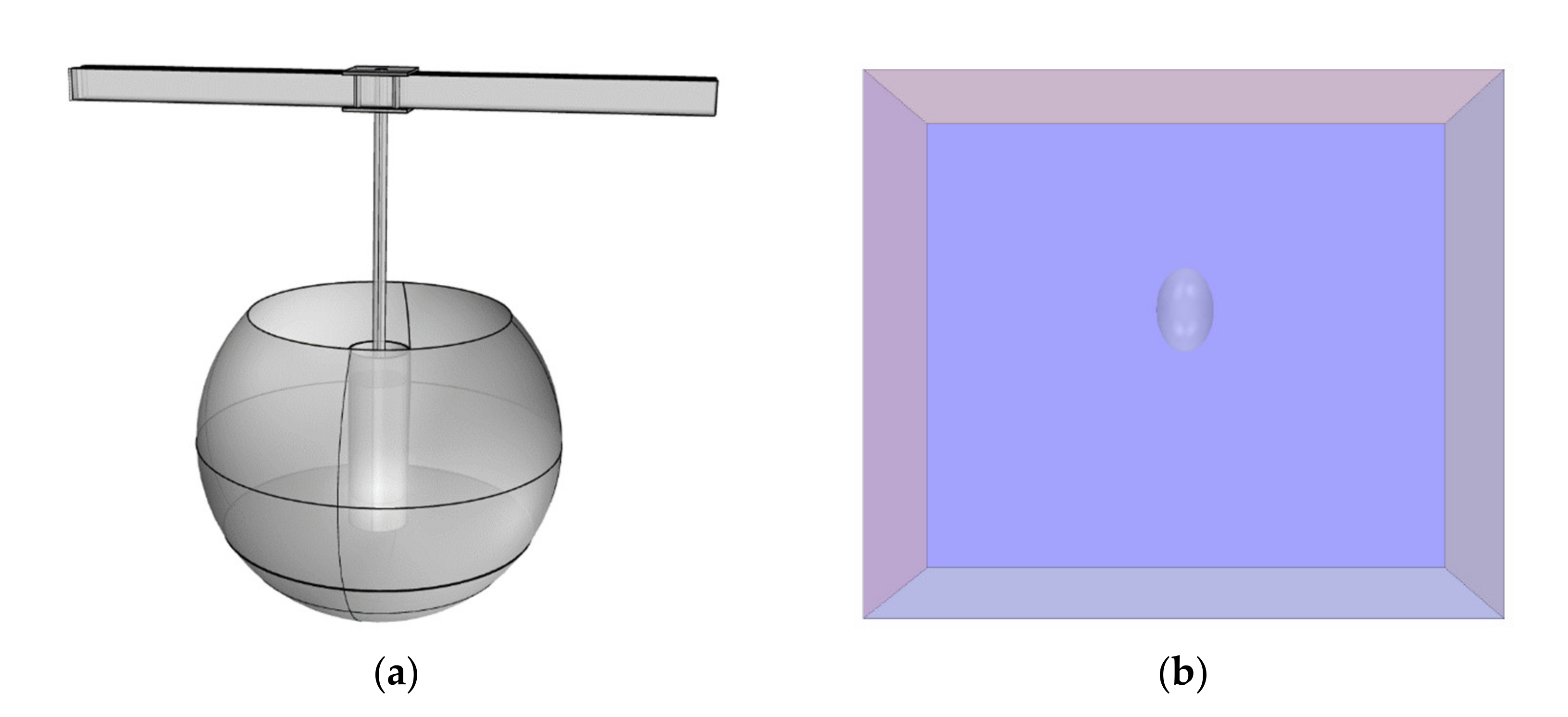
2. Methods and Model

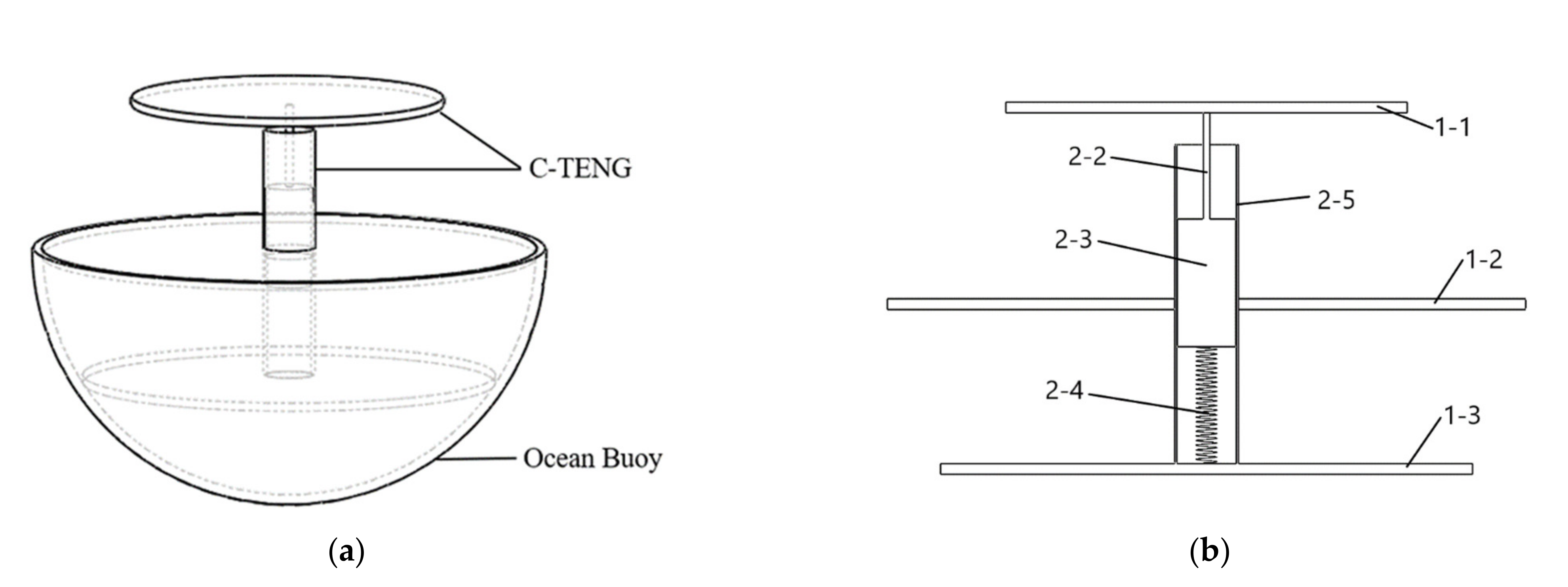
Model of BUOY-41 with a Built-In C-TENG

The upper part of the buoy is a hollow floating ball and the internal space of the floating ball is used to install C-TENG. The whole assembly consists of an ocean buoy and a built-in C-TENG. The C-TENG is installed inside of the ocean buoy, fixed to the inside wall by two fixed plates (Figure 2a). As shown in Figure 2b, the structure of C-TENG consists of a hollow cylinder (2-5), a spring (2-4) and a mass block (2-3) with two fixed plates (1-2, 1-3), an active plate (1-1) and a connecting rod (2-2). The bottom of the cylinder is connected with the mass block by the spring. Two different kinds of nanometer materials films, PTFE and nylon, were attached to the outer surface of the mass block (PTFE) and the inner face of the cylinder (nylon). Triggered by water waves, the mass block will swing in the hollow cylinder, and the mechanical energy will be converted into electrical energy. The advantage of this structure is that it can make full use of the vertical motion in the wave, which is the concentrated part of wave waves, so that the wave energy can be converted into electrical energy more effectively.

3. Results and Discussions

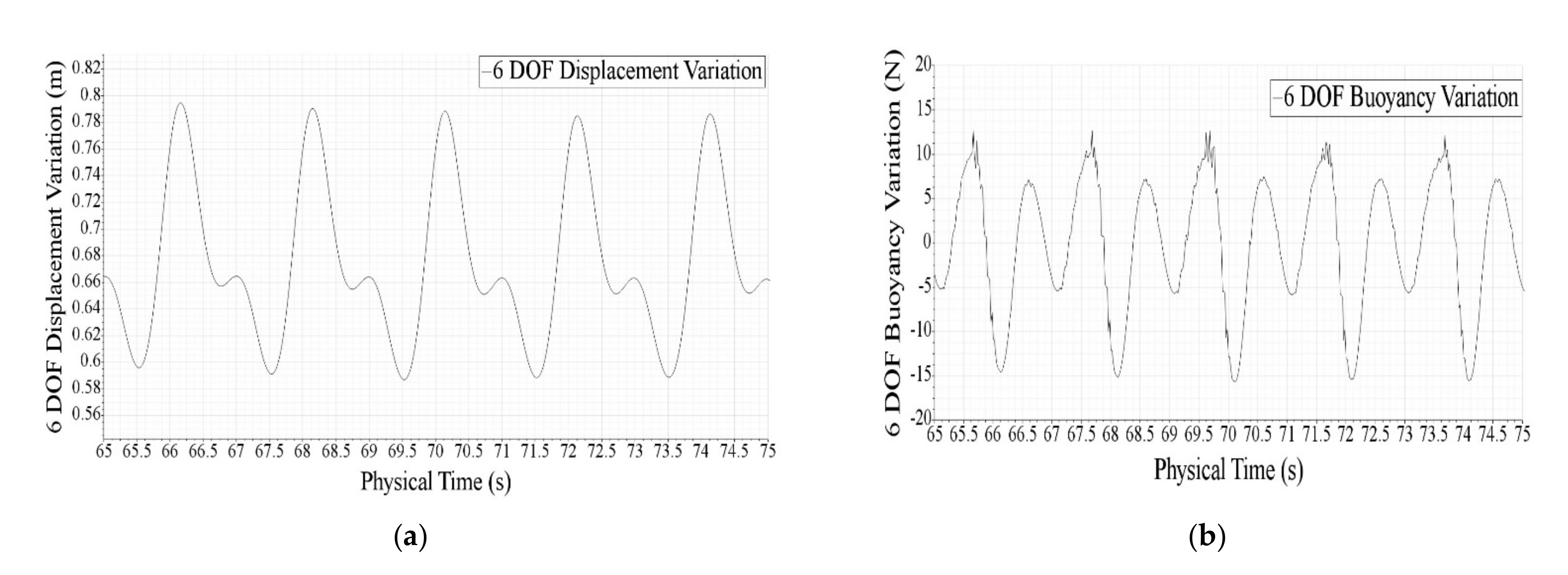
3.1. Hydrodynamic Properties of Ocean Buoy

Since the water sail has little effect on the vertical motion of floating buoy and the influence of water sail on TENG can be ignored, only the motion of the sphere needs to be considered. As shown in Figure 3a, in order to simplify the calculation, the mass block is connected with the crane through the fixing device. Therefore, the motion of the sphere is the relative motion between the C-TENG and the buoy. The C-TENG is installed inside the ocean buoy and its hydrodynamic properties are consistent with that of the ocean buoy, so we only need to study the hydrodynamic properties of the ocean buoy. The calculation model adopted this time is mainly an ocean buoy with a diameter of 600 mm and a cuboid with a computational domain of 10 m × 2 m × 5 m, as shown in Figure 3b. The method we adopted for grid setting was automatic grid generation with base size of 0.5 m. In order to more accurately study the motion pattern of the ocean buoy, the water surface and waves are encrypted with three grids. In addition, we also carried out mesh encryption for the ocean buoy for three times. The boundary conditions are mainly set for the computational domain and sphere. The calculation domain mainly sets six boundary conditions. The Bottom, we need to make the wall impermeable; For inlet is a speed inlet; Outlet is pressure outlet; Symmetry is the plane of symmetry; Top stands for pressure outlet. The boundary condition Settings for the Sphere are mainly Sphere Surface (wall) and Block Surface. In addition to setting basic physical quantities such as air and water, the initial conditions mainly require setting the parameters of waves. BUOY-41 is used in the Yellow Sea and Bohai Sea. According to the data, the average wave height of the Yellow Sea and Bohai Sea is about 0.4 m, and the period is between 2 s and 4 s. Therefore, the 0.4 m wave height and 2 s period are selected as the wave condition. Waves are mainly fifth-order stokes waves with a wave period of 2 s, a wave height of 0.4 m and a water depth of 5 m. In addition, the Volume Fraction of all parameters is set as composite. Air field function is Volume Fraction of Light Fluid of fifth-order VOF wave, water field function is Volume Fraction of Heavy Fluid of fifth-order VOF wave, and Pressure field function is Hydrostatic Pressure of fifth-order VOF wave.
For the hydrodynamic properties, we mainly calculated and analyzed the vertical displacement variation and buoyancy variation. The calculated step length was 0.02 and the maximum limiting time was 85 s. Figure 4a,b, respectively, represent the vertical displacement change and 6-DOF buoyancy change of the ocean buoy. From Figure 4a, it is observed that the motion of the ocean buoy tends to be stable from about 70 s, and the maximum displacement can reach 0.19 m. By comparing the buoyancy diagram of the ocean buoy, we found that the force variation of the ocean buoy tends to be stable from 37.74 s, and the maximum buoyancy reaches 13.62 N. Through the above simulation results, we found that under the condition of stable force, the ocean buoy could produce a good displacement, so we could import the displacement function into COMSOL for further simulation.

3.2. Energy Capture Properties of C-TENG

COMSOL is convenient for simulation of electric field. The model used in this paper is shown in Figure 5. The dimensions used in the simulation approximate the dimensions of the actual manufactured equipment. The establishment of the entire simulation condition is based on actual experiments, and the air boundary is set. A sufficiently large space is used as the simulation calculation domain, and the space boundary is set to the potential zero point. The materials used in C-TENG are copper, PTFE and nylon. Since the thickness of the friction medium is much smaller than its width, any overlapping area between the electrodes can use the simplified model of the parallel plate capacitor and ignore its boundary effect. Due to the electrical effect of friction, the same amount of different charges will be attached to the surface of the friction medium. Since the thickness of the material film and the copper plating layer is quite thin, in order to obtain sufficient calculation accuracy, the grid in the middle area of the calculation domain needs to be encrypted, and the surrounding grid should be dealt with at the same time.

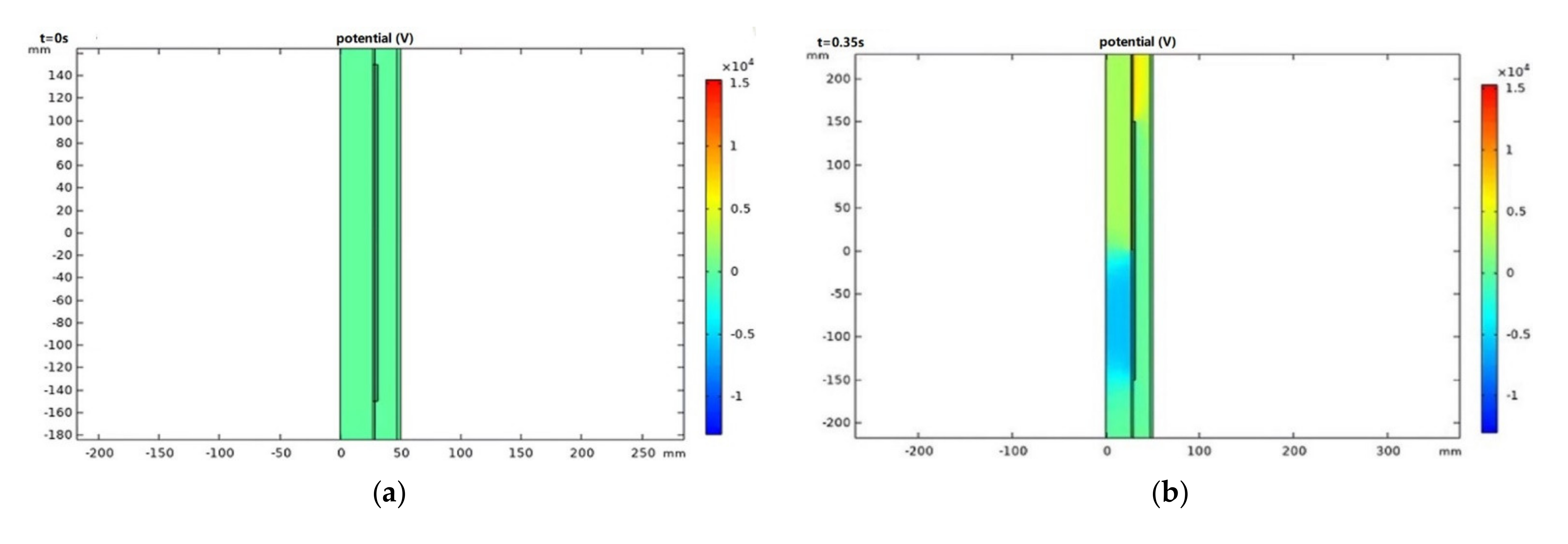
3.2.1. Electric Potential Distribution

The potential distribution is obtained through simulation. Since the two contact materials are insulators, the designed charge is evenly distributed on the contact surface. Figure 6a–d in one cycle shows the potential distribution in different stages. When the electrode is at central position, the potential is 0. For electrode sliding to the upper edge, the potential difference between the two electrodes reaches the positive maximum value. Then, the potential becomes reverse maximum value with the electrode moving to the bottom, and finally returns to 0. When moving up or down to the limit position, the potential difference between the two electrodes reaches the maximum value. Therefore, the finite element simulation shows that the slider will generate a periodic electrical signal in each movement cycle. The results of such potential changes also verify the power generation principle of the C-TENG. Then we try to change the resistance, the gap between friction layers, and surface charge density to obtain open-circuit voltage and short-circuit current of different situations.

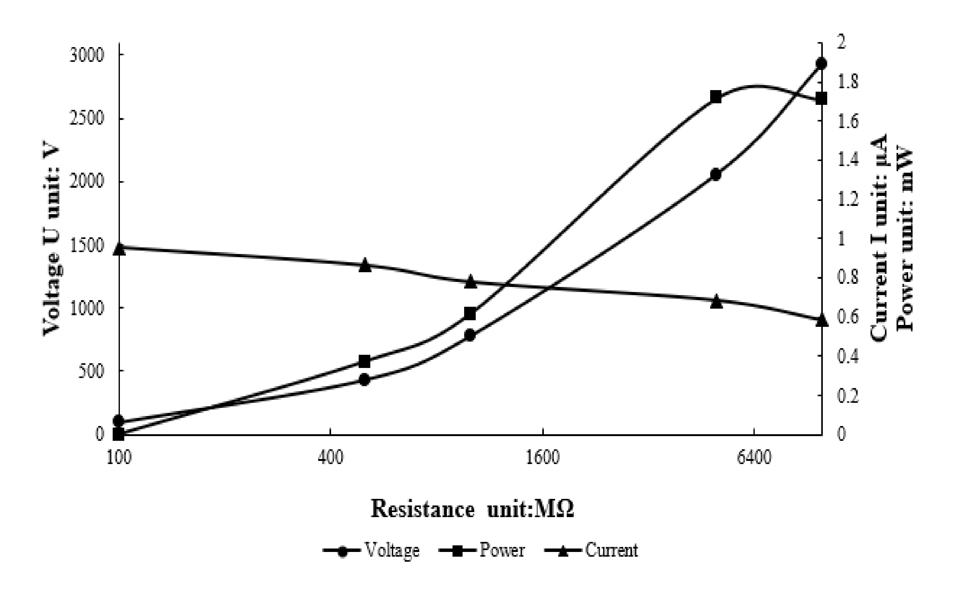
3.2.2. Influence of Resistance

Different from the traditional electromagnetic induction generator, it is capacitive. It has very high internal impedance, so the load resistance has a great influence on the output performance, and there is an optimal resistance matching problem. Therefore, in COMSOL software, we design the models with the resistance of 100 MΩ, 500 MΩ, 1000 MΩ, 5000 MΩ, 104 MΩ. Through the simulation results obtained, we can draw the chart of the peak voltage, current and power under different resistances. The results curve is shown in Figure 7. The influence of external load resistance on the output power was studied. The changes of current, voltage and power under different load resistances are obtained through the simulation. The results show that the peak value of current decreases with the increase of load resistance, while the peak value of voltage increases with the increase of load resistance. The output power increases first and then decreases with the resistance increasing, and reaches the maximum when the resistance is 5000 MΩ. It can be seen from Figure 7 that the maximum peak power is about 1.716 mW. According to the designed model parameters, the inner radius of the cylinder is 0.03 m, the length is 0.3 m, and the contact area of the two electrodes of the C-TENG is 0.0565 m2. Therefore, the power density is about 30 mW/m2.

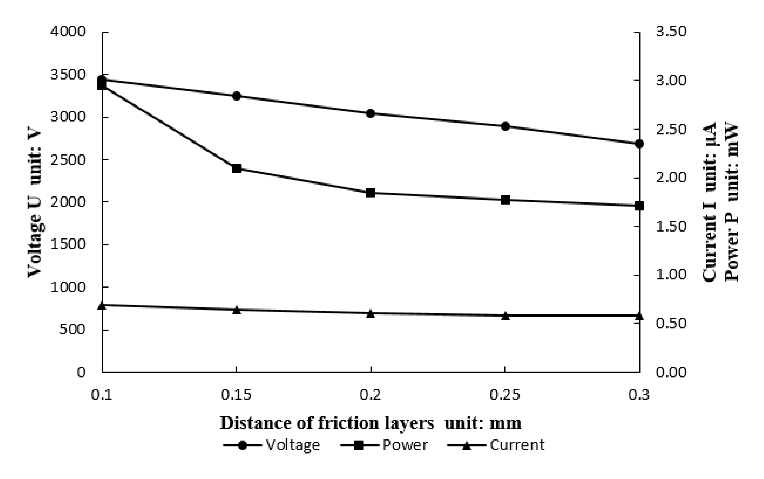
3.2.3. Influence of Friction Layer Distance

The potential between the two electrodes varies with the distance between the friction layers. Based on the above analysis, the resistance of 5000 MΩ is selected when the power is most reasonable. The friction layer distance is set to 0.1 mm, 0.15 mm, 0.2 mm, 0.25 mm and 0.3 mm, respectively, for simulation. It can be seen from the analysis (Figure 8) that the open-circuit voltage decreases with the increase of the distance between friction layers. According to the simulation conditions, the electric charge is evenly distributed on the inner surface of the polymer, and the electric field is formed inside the two insulators and the air gap. The transferred electric charge determines the electric field strength. When the distance of friction layers is relatively small, the electron transfer is more sufficient. The change of the electric potential proves the electric principle of C-TENG that power generation of C-TENG relies on the electron transfer between the friction layers.

3.2.4. Influence of Friction Charge Density

Keeping the other parameters unchanged, we can observe the effect of surface charge density on the output power. The results (Figure 9) show that the voltage, current and power of C-TENG are obviously enhanced by improving the charge density of the electrode. We can choose the materials with large difference in triboelectric properties as electrodes, which have a huge influence on triboelectric. Also, the improvement of dielectric materials can also offset part of the energy loss of C-TENG. Many scholars have made attempts and conducted research on improving dielectric materials.

4. Conclusions

In summary, we demonstrated a C-TENG for efficiently harvesting low-frequency ocean wave energy, which includes a mass block into a hollow cylinder. The C-TENG is based on the lateral sliding mode, which is more suitable for scavenging the wave energy of vertical motion compared with other TENGs. Verified by the finite element simulations, the C-TENG has high power density and is suitable for powering for the ocean buoy, BUOY-41. Under the wave condition of 0.4 m and 2 s, we can observe that the maximum displacement and buoyancy of the ocean buoy can reach 0.19 m and 13.62 N. The maximum power output density can arrive at 30 mW/m2. It is expected that the proposed C-TENG array may provide a promising way for self-powered buoys. This research may provide a new method to study triboelectric nanogenerator theoretically, which is of great academic value and practical significance for the development of triboelectric nanogenerator technology.

Author Contributions

Conceptualization, H.L. and F.Y.; methodology, H.L. and F.Y.; software, F.Y. and Y.J.; validation, Y.J.; formal analysis, H.L., F.Y. and Y.J.; investigation, F.Y. and W.L.; resources, H.L. and H.C.; data curation, F.Y. and Y.J.; writing—original draft preparation, H.L. and F.Y.; writing—review and editing, H.L. and Y.J.; visualization, W.L. and H.C.; supervision, Y.J. and F.K.; project administration, F.K.; funding acquisition, H.L. All authors have read and agreed to the published version of the manuscript.

Funding

This research is financially supported by the National Natural Science Foundation (Grant No. 52071095. and No. 51979063), the basic research and cutting-edge technology projects of State Administration for Science, Technology and Industry for National Defense (CN) (Grant No. JCKY2019604C003).

Institutional Review Board Statement

Not applicable.

Informed Consent Statement

Not applicable.

Data Availability Statement

Not applicable.

Conflicts of Interest

The authors declare no conflict of interest.

References

  1. Khaligh, A.; Onar, O.C. Energy Harvesting: Solar, Wind, and Ocean Energy Conversion Systems; Taylor Francis Group: Abingdon, UK, 2017; pp. 1–368. [Google Scholar]
  2. Gielen, D.; Boshell, F.; Saygin, D. Climate and energy challenges for materials science. Nat. Mater. 2016, 15, 117–120. [Google Scholar] [CrossRef] [PubMed]
  3. Chu, S.; Majumdar, A. Opportunities and challenges for a sustainable energy future. Nat. Cell Biol. 2012, 488, 294–303. [Google Scholar] [CrossRef] [PubMed]
  4. Astariz, S.; Iglesias, G. The economics of wave energy: A review. Renew. Sustain. Energy Rev. 2015, 45, 397–408. [Google Scholar] [CrossRef]
  5. Xu, G.; Shen, W.; Wang, X. Applications of Wireless Sensor Networks in Marine Environment Monitoring: A Survey. Sensors 2014, 14, 16932–16954. [Google Scholar] [CrossRef] [Green Version]
  6. Yuh, J.; Marani, G.; Blidberg, D.R. Applications of marine robotic vehicles. Intell. Serv. Robot. 2011, 4, 221–231. [Google Scholar] [CrossRef]
  7. Salter, S.H. Wave power. Nat. Cell Biol. 1974, 249, 720–724. [Google Scholar] [CrossRef]
  8. Falnes, J. A review of wave-energy extraction. Mar. Struct. 2007, 20, 185–201. [Google Scholar] [CrossRef]
  9. Von Jouanne, A. Harvesting the waves. Mech. Eng. Mag. Sel. Artic. 2006, 128, 24–27. [Google Scholar] [CrossRef] [Green Version]
  10. Drouen, L.; Charpentier, J.F.; Semail, E.; Clenet, S.B.T.-O. Study of an Innovative Fitted to Marine Current Turbines. In OCEANS 2007-Europe; IEEE: New York, NY, USA, 18 June 2007; pp. 1–6. [Google Scholar]
  11. Fan, F.-R.; Tian, Z.-Q.; Wang, Z.L. Flexible triboelectric generator. Nano Energy 2012, 1, 328–334. [Google Scholar] [CrossRef]
  12. Xiang, C.; Liu, C.; Hao, C.; Wang, Z.; Che, L.; Zhou, X. A self-powered acceleration sensor with flexible materials based on triboelectric effect. Nano Energy 2017, 31, 469–477. [Google Scholar] [CrossRef]
  13. Niu, S.; Wang, Z.L. Theoretical systems of triboelectric nanogenerators. Nano Energy 2015, 14, 161–192. [Google Scholar] [CrossRef] [Green Version]
  14. Jiang, T.; Chen, X.; Han, C.B.; Tang, W.; Wang, Z.L. Theoretical Study of Rotary Freestanding Triboelectric Nanogenerators. Adv. Funct. Mater. 2015, 25, 2928–2938. [Google Scholar] [CrossRef]
  15. Yang, H.; Liu, W.; Xi, Y.; Lai, M.; Guo, H.; Liu, G.; Wang, M.; Li, T.; Ji, X.; Li, X. Rolling friction contact-separation mode hybrid triboelectric nanogenerator for mechanical energy harvesting and self-powered multifunctional sensors. Nano Energy 2018, 47, 539–546. [Google Scholar] [CrossRef]
  16. Xia, K.; Zhu, Z.; Zhang, H.; Du, C.; Fu, J.; Xu, Z. Milk-based triboelectric nanogenerator on paper for harvesting energy from human body motion. Nano Energy 2019, 56, 400–410. [Google Scholar] [CrossRef]
  17. Gu, G.Q.; Han, C.B.; Tian, J.J.; Lu, C.X.; He, C.; Jiang, T.; Li, Z.; Wang, Z.L. Antibacterial composite film-based triboelectric nan-ogenerator for harvesting walking energy. ACS Appl. Mater. Interfaces 2017, 9, 11882. [Google Scholar] [CrossRef] [PubMed]
  18. Liu, G.X.; Li, W.J.; Liu, W.B.; Bu, T.Z.; Guo, T.; Jiang, D.D.; Zhao, J.Q.; Ben Xi, F.; Hu, W.G.; Zhang, C. Soft Tubular Triboelectric Nanogenerator for Biomechanical Energy Harvesting. Adv. Sustain. Syst. 2018, 2, 1800081. [Google Scholar] [CrossRef]
  19. Chen, B.; Tang, W.; Jiang, T.; Zhu, L.; Chen, X.; He, C.; Xu, L.; Guo, H.; Lin, P.; Li, D.; et al. Three-dimensional ultra-flexible triboelectric nanogenerator made by 3D printing. Nano Energy 2018, 45, 380–389. [Google Scholar] [CrossRef]
  20. Tang, W.; Han, C.B.; Zhang, C.; Wang, Z.L. Cover-sheet-based nanogenerator for charging mobile electronics using low-frequency body motion/vibration. Nano Energy 2014, 9, 121–127. [Google Scholar] [CrossRef]
  21. Wang, J.; Ding, W.; Pan, L.; Wu, C.; Yu, H.; Yang, L.; Liao, R.; Wang, Z.L. Self-Powered Wind Sensor System for Detecting Wind Speed and Direction Based on a Triboelectric Nanogenerator. ACS Nano 2018, 12, 3954–3963. [Google Scholar] [CrossRef]
  22. Wang, P.; Pan, L.; Wang, J.; Xu, M.; Dai, G.; Zou, H.; Dong, K.; Wang, Z.L. An Ultra-Low-Friction Triboelectric–Electromagnetic Hybrid Nanogenerator for Rotation Energy Harvesting and Self-Powered Wind Speed Sensor. ACS Nano 2018, 12, 9433–9440. [Google Scholar] [CrossRef]
  23. Zhang, C.; Zhang, Z.H.; Yang, X.; Zhou, T.; Han, C.B.; Wang, Z.L. Tribotronic Phototransistor for Enhanced Photodetection and Hybrid Energy Harvesting. Adv. Funct. Mater. 2016, 26, 2554–2560. [Google Scholar] [CrossRef]
  24. Zheng, L.; Lin, Z.-H.; Cheng, G.; Wu, W.; Wen, X.; Lee, S.; Wang, Z.L. Silicon-based hybrid cell for harvesting solar energy and raindrop electrostatic energy. Nano Energy 2014, 9, 291–300. [Google Scholar] [CrossRef] [Green Version]
  25. Wijewardhana, K.R.; Shen, T.-Z.; Jayaweera, E.; Shahzad, A.; Song, J.-K. Hybrid nanogenerator and enhancement of water–solid contact electrification using triboelectric charge supplier. Nano Energy 2018, 52, 402–407. [Google Scholar] [CrossRef]
  26. Liu, Y.; Sun, N.; Liu, J.; Wen, Z.; Sun, X.; Lee, S.-T.; Sun, B. Integrating a Silicon Solar Cell with a Triboelectric Nanogenerator via a Mutual Electrode for Harvesting Energy from Sunlight and Raindrops. ACS Nano 2018, 12, 2893–2899. [Google Scholar] [CrossRef]
  27. Jiang, T.; Zhang, L.M.; Chen, X.; Han, C.B.; Tang, W.; Zhang, C.; Xu, L.; Wang, Z.L. Structural optimization of triboelectric nan-ogenerator for harvesting water wave energy. ACS Nano 2015, 9, 12562–12572. [Google Scholar] [CrossRef]
  28. Zhang, L.M.; Han, C.B.; Jiang, T.; Zhou, T.; Li, X.H.; Zhang, C.; Wang, Z.L. Multilayer wavy-structured robust triboelectric nan-ogenerator for harvesting water wave energy. Nano Energy 2016, 22, 87–94. [Google Scholar] [CrossRef]
  29. Ouro, P.; Juez, C.; Franca, M. Drivers for mass and momentum exchange between the main channel and river bank lateral cavities. Adv. Water Resour. 2020, 137, 103511. [Google Scholar] [CrossRef]
  30. Ballard, Z.; Mann, B. Experimental and Numerical Investigations of an Untethered, Nonlinear Spherical Buoy in a Wave Tank. In Proceedings of the International Design Engineering Technical Conferences and Computers and Information in Engineering Conference, Washington, DC, USA, 28–31 August 2011; Volume 54785, pp. 429–437. [Google Scholar]
  31. Ballard, Z.; Mann, B.P. Two-Dimensional Nonlinear Analysis of an Untethered Spherical Buoy Due to Wave Loading. J. Comput. Nonlinear Dyn. 2013, 8, 041019. [Google Scholar] [CrossRef]
  32. David, F.G.; Murray, R.; Raymond, C.Z. Cohen Wave interaction with a tethered buoy: SPH simulation and experimental validation. Ocean Eng. 2018, 156, 306–317. [Google Scholar]
  33. Lin, H.; Yim, S.C. Coupled Surge-Heave Motions of a Moored System. I: Model Calibration and Parametric Study. J. Eng. Mech. 2006, 132, 671–680. [Google Scholar] [CrossRef]
  34. Zhu, X.; Yoo, W.S. Numerical modeling of a spherical buoy moored by a cable in three dimensions. Chin. J. Mech. Eng. 2016, 29, 588–597. [Google Scholar] [CrossRef]
  35. Zhu, X.; Yoo, W.S. Dynamic analysis of a floating spherical buoy fastened by mooring cables. Ocean Eng. 2016, 121, 462–471. [Google Scholar] [CrossRef]
  36. Yang, W.; Wang, X.; Li, H.; Wu, J.; Hu, Y.; Li, Z.; Liu, H. Fundamental research on the effective contact area of micro-/nano-textured surface in triboelectric nanogenerator. Nano Energy 2019, 57, 41–47. [Google Scholar] [CrossRef]
  37. Niu, S.; Liu, Y.; Chen, X.; Wang, S.; Zhou, Y.S.; Lin, L.; Xie, Y.; Wang, Z.L. Theory of freestanding triboelectric-layer-based nanogenerators. Nano Energy 2015, 12, 760–774. [Google Scholar] [CrossRef] [Green Version]
  38. Niu, S.; Wang, S.; Liu, Y.; Zhou, Y.S.; Lin, L.; Hu, Y.; Pradel, K.C.; Wang, Z.L. A theoretical study of grating structured triboelectric nanogenerators. Energy Environ. Sci. 2014, 7, 2339–2349. [Google Scholar] [CrossRef]
  39. Wei, Z.; Geng, L.; Bian, S. Equivalent circuit models of triboelectric nanogenerators. ZTE Technol. 2018. [Google Scholar] [CrossRef]
  40. Zhang, D.; Shi, J.; Si, Y.; Li, T. Multi-grating triboelectric nanogenerator for harvesting low-frequency ocean wave energy. Nano Energy 2019, 61, 132–140. [Google Scholar] [CrossRef]
  41. Lin, W.Z.; Han, C.B.; Jiang, T.; Zhang, C.; Wang, Z.L. A ball-bearing structured triboelectric nanogenerator for nondestructive damage and rotating speed measurement. Nanotechnology 2016, 27, 085401. [Google Scholar] [CrossRef]
  42. Liu, W.; Xu, L.; Bu, T.; Yang, H.; Liu, G.; Li, W.; Pang, Y.; Hu, C.; Zhang, C.; Cheng, T. Torus structured triboelectric nanogenerator array for water wave energy harvesting. Nano Energy 2019, 58, 499–507. [Google Scholar] [CrossRef]
  43. Han, C.B.; Du, W.; Zhang, C.; Tang, W.; Zhang, L.; Wang, Z.L. Harvesting energy from automobile brake in contact and non-contact mode by conjunction of triboelectrication and electrostatic-induction processes. Nano Energy 2014, 6, 59–65. [Google Scholar] [CrossRef]
Figure 1. BUOY-41 (a) overall structure; (b) internal structure.
Applsci 11 03076 g001
Figure 2. Model of C-TENG. (a) model of the assembly; (b) cutaway view of C-TENG.
Applsci 11 03076 g002
Figure 3. Model of C-TENG for hydrodynamic calculation. (a) Fixing device of the C-TENG; (b) calculation domain.
Applsci 11 03076 g003
Figure 4. Image of hydrodynamic properties. (a) displacement variation; (b) buoyancy variation.
Applsci 11 03076 g004
Figure 5. Calculation model of energy capture properties.
Applsci 11 03076 g005
Figure 6. Potential distribution in different stages. (a) The sliding electrode at the center (t = 0 s); (b) the sliding electrode at the top (t = 0.35 s); (c) the sliding electrode at the bottom (t = 1.1 s); (d) the sliding electrode back to the center (t = 2 s).
Applsci 11 03076 g006aApplsci 11 03076 g006b
Figure 7. Peak power, current and voltage vary with resistance.
Applsci 11 03076 g007
Figure 8. Peak power, current and voltage vary with distance.
Applsci 11 03076 g008
Figure 9. Peak power, current and voltage vary with charge density.
Applsci 11 03076 g009
Publisher’s Note: MDPI stays neutral with regard to jurisdictional claims in published maps and institutional affiliations.

