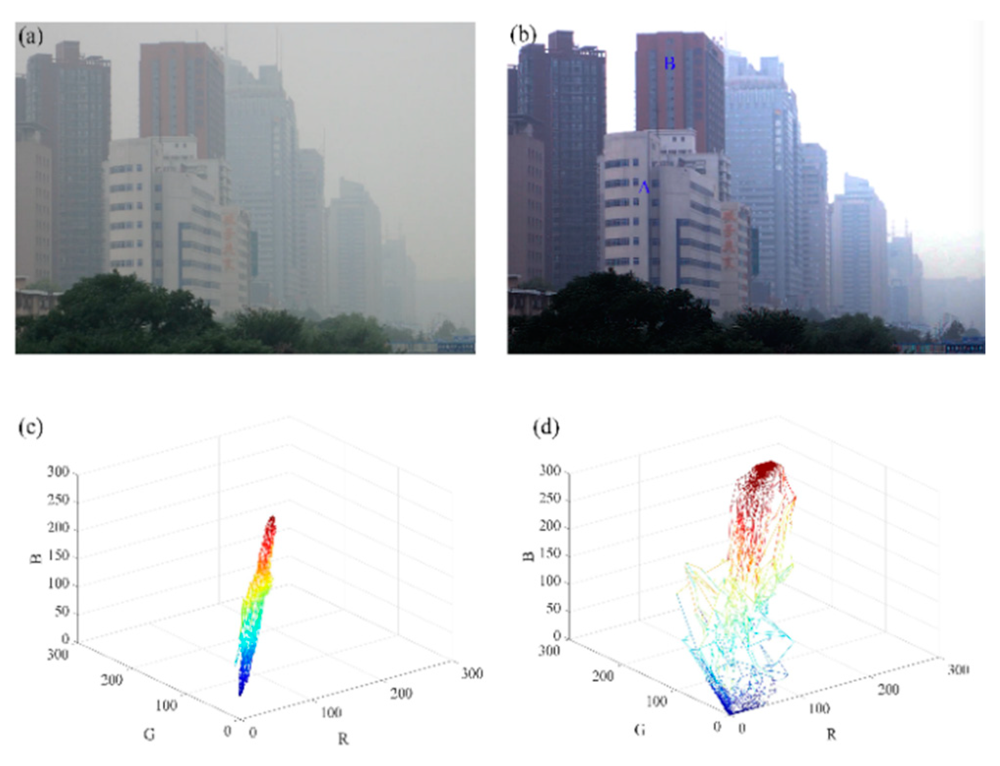
Article

Advanced Visualization Polarimetric Imaging: Removal of Water Spray Effect Utilizing Circular Polarization

1
School of Physics and Optoelectronic Engineering, Xidian University, Xi’an 710071, China
2
Xi’an Key Laboratory of Computational Imaging, Xi’an 710071, China
3
Academy of Advanced Interdisciplinary Research, Xi’an 710071, China
4
Key Laboratory of Optical Engineering, Chinese Academy of Sciences, Chengdu 610209, China
*
Author to whom correspondence should be addressed.
Appl. Sci. 2021, 11(7), 2996; https://doi.org/10.3390/app11072996
Submission received: 21 January 2021 / Revised: 25 March 2021 / Accepted: 25 March 2021 / Published: 26 March 2021
(This article belongs to the Special Issue State-of-the-Art Laser Measurement Technologies)

Abstract

:
Circular polarization (CP) memory is a well-known phenomenon whereby natural light becomes partially circularly polarized after scattering by water spray several times, and the circularly polarized state can be well preserved within a certain propagation distance. In this study, a CP imaging method combined with the multi-scale analysis in the frequency domain is proposed to enhance the vision in rainy conditions. The images were first decomposed into multi-scales. CP characteristics of light were employed in the low-frequency parts to improve the quality of images in rainy conditions, and the high-frequency parts compensated specific structure information. Experimental results demonstrate that the proposed method can remove the water spray effect thereby improving the vision of degraded rainy-day images.

1. Introduction

Techniques for imaging through turbid media have recently received considerable attention because of their potential applications such as atmosphere remote sensing, underwater photography, and even biomedical imaging [1,2,3]. The major difficulty encountered in these techniques is the loss of directionality of the incident light caused by multiple scattering among particles (water spray, dust, etc.), which leads to degradation of the image quality [4,5,6].
Several studies that focused on polarimetric imaging techniques are of great interest [7,8,9]. By retaining and displaying polarization differences between airlight (natural illumination) and the direct transmission of light through an object in polarization images, polarimetric imaging can make it possible to enhance the visibility and contrast of images taken through turbid media. Schechner, Fang, Liu, and collaborators [10,11,12,13] mainly focused on image dehazing by employing linearly polarized information on light based on the fact that airlight is partially polarized light that can be detected. However, linear polarization (LP)-based methods rarely show satisfactory recovery results when it comes to rainy-day images. Two major reasons account for this phenomenon: one is the attenuation of thick clouds on rainy days, which causes a sharp reduction in the amount of light captured by cameras, but the circular polarization (CP) information in the scene remains stable based on the CP memory effect; the other is the characteristic of water spray, by which the interaction between airlight and water spray can turn natural light into circularly polarized light [14,15,16]. Moreover, since CP light is point-symmetric, it does not depend on the scattering angle, and can survive more multi-scattering events than linearly polarized light does [17]. The CP light maintains better polarization characteristics than LP for both forward and backward scattering, as shown in Figure 1a. The effects of size on the degree of polarization are shown in Figure 1b. The degree of polarization (DOP) is greater for LP than for CP for small sizes. When the size parameter is large, such as with a water drop, the DOP for CP is greater than for LP [18]. The circular polarization characteristics of light have been used in an effort to improve the image quality of underwater targets [19]. It provides another possible way to compensate for the deficiency of LP-based technologies in enhancing rainy-day image quality.
In this study, we first analyzed limitations of traditional polarization image recovery methods based on linearly polarized light and then reported a CP imaging method combining the multi-scale analysis to image in rainy conditions and enhance visibility. Several scenes on a rainy day were captured using CP imaging devices. Then, the images were decomposed into various spatial frequency layers using wavelet transform. This operation concentrates the polarization information from objects and water spray to the low-spatial frequency components of the image; meanwhile, the specific structure information is concentrated to the high-spatial frequency components of the image. Furthermore, the degraded image could be recovered by employing the CP characteristics from the low-spatial frequency components. At the same time, the high-spatial frequency components were manipulated to reconstruct the details of the images by the nonlinear transform method. Experiments in rainy-day conditions were performed to demonstrate the effectiveness of the proposed method.

2. Materials and Methods

2.1. Optical Model of Rainy Conditions

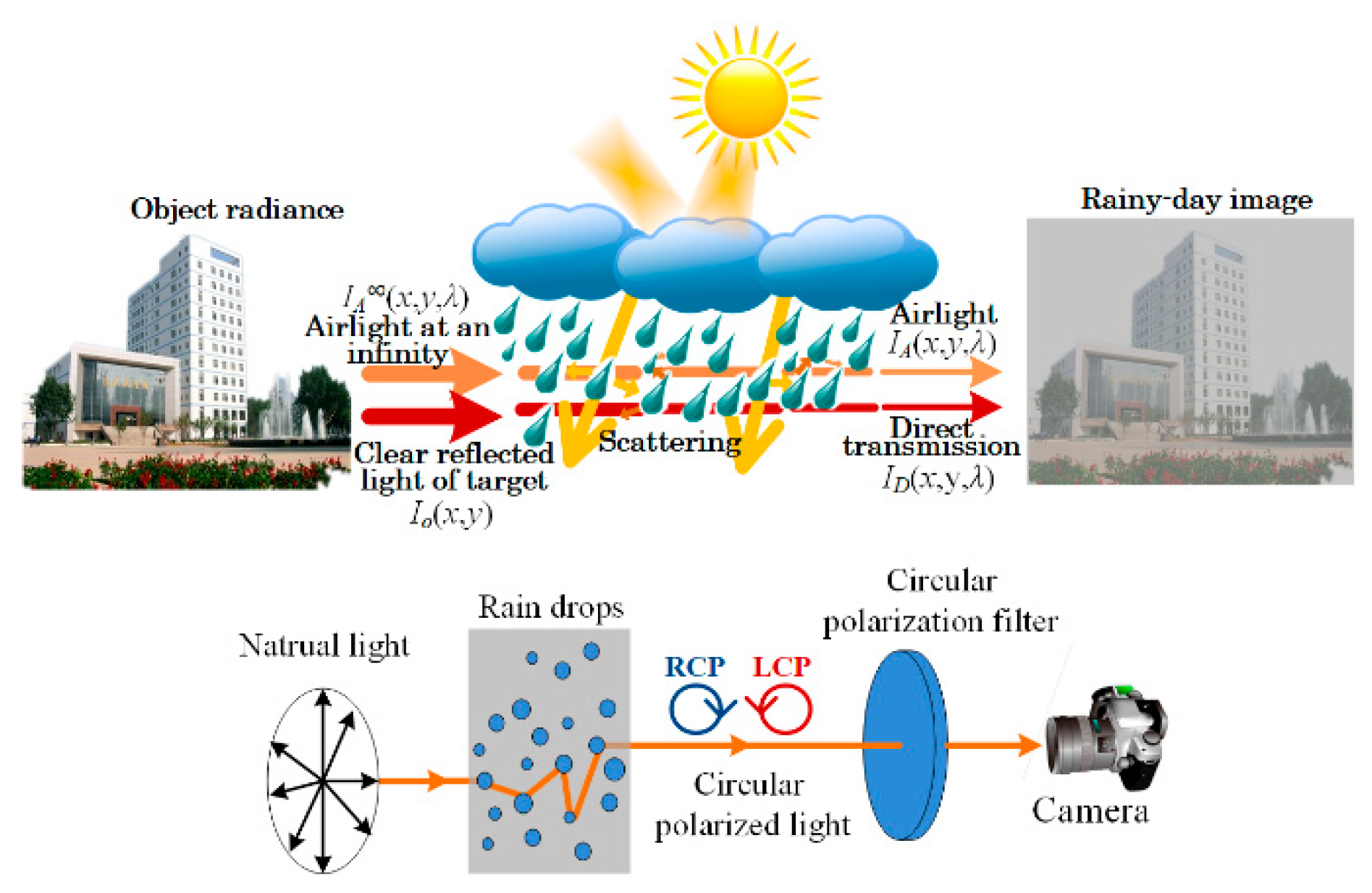
As shown in Figure 2, the thick clouds heavily reduce the intensity of natural light, which leads to a reduction in image brightness. In addition, along with the rain, there is an abundance of water spray in the air that generates scattering of light [16]. The reflected light of different bands has different transmissivity mapping. Hence, images taken through this kind of scattering media are characterized by a loss of contrast and changes in color. Even though there is serious image degradation, the specific atmospheric conditions on rainy days provide the possibility to image through the rain by employing circularly polarized information. Several studies on the propagation of light through water spray have demonstrated that for randomly oriented particles [15,16,17], the incident light (sunlight before into the water spray) [S0(x, y), S1(x, y), S2(x, y), S3(x, y)]T and the scattered light (reflected light from target surface) [S00(x, y), S10(x, y), S20(x, y), S30(x, y)]T are related by Equation (1):
[ S 0 ( x , y ) , S 1 ( x , y ) , S 2 ( x , y ) , S 3 ( x , y ) ] T = L ( π i 2 ) P ( ψ ) L ( i 1 ) [ S 0 0 ( x , y ) , S 1 0 ( x , y ) , S 2 0 ( x , y ) , S 3 0 ( x , y ) ] T = ( p 11 ( ψ ) p 21 ( ψ ) cos 2 i 1 p 21 ( ψ ) sin 2 i 1 0 p 21 ( ψ ) cos 2 i 2 p 22 ( ψ ) cos 2 i 1 cos 2 i 2 p 33 ( ψ ) sin 2 i 2 sin 2 i 1 ( p 22 ( ψ ) cos 2 i 2 sin 2 i + p 33 ( ψ ) sin 2 i 2 cos 2 i 1 ) p 43 ( ψ ) sin 2 i 2 p 21 ( ψ ) sin 2 i 2 p 22 ( ψ ) sin 2 i 2 cos 2 i 1 + p 33 ( ψ ) × sin 2 i 1 cos 2 i 2 p 33 ( ψ ) cos 2 i 2 cos 2 i 1 p 22 ( ψ ) sin 2 i 1 sin 2 i 2 p 43 ( ψ ) cos 2 i 2 0 p 43 ( ψ ) sin 2 i 1 p 43 ( ψ ) cos 2 i 1 p 44 ( ψ ) ) ( S 0 0 ( x , y ) S 1 0 ( x , y ) S 2 0 ( x , y ) S 3 0 ( x , y ) )   ,
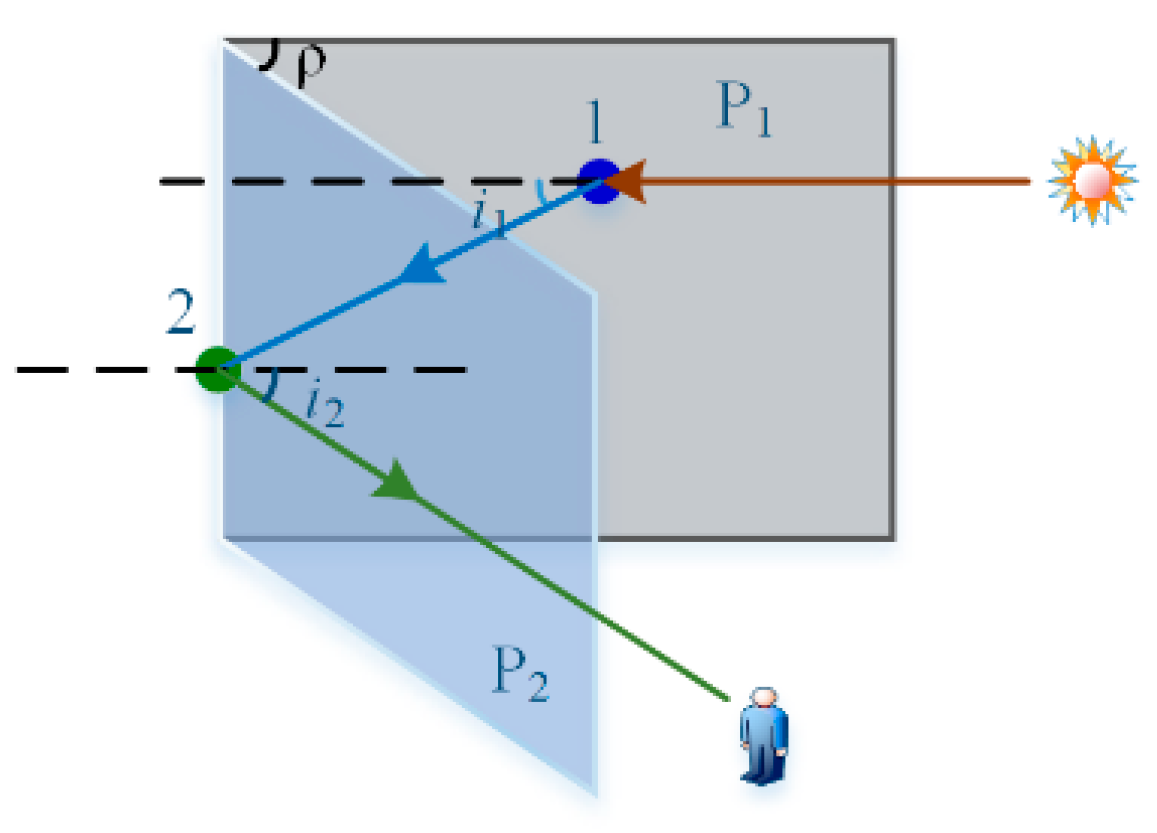
where p is the phase matrix; Ψ means the scattering angle; i1 and i2 are the angles of rotation of the light scattered by water molecules; L is the rotation matrix; (((S1(x, y))2 + (S2(x, y))2)1/2/S0(x, y)) is the Degree of LP (DoLP); (S3(x, y)/S0(x, y)) is the Degree of CP (DoCP) [15]. The LP light ([S01(x, y), S11(x, y), 0, 0]T) exists after a single scattering with sunlight as the incident light. It is also possible for CP light to be generated when the incident light experiences multiple scattering according to Equation (1). Können [16] also stated the fact that a rainy day or watery environment is a very specific condition that can generate more circularly polarized light through multi-scattering in a natural environment compared to a sunny day. Under natural conditions, multiple scattering is much more common than single scattering in media [15,18]. Taking two-particle scattering as an example (Figure 3), the CP component S32(ψ, ρ) can be written as Equation (2):
S 3 2 ( ψ , ρ ) = 2 P 21 ( ψ ) P 43 ( ψ ) sin ψ sin ρ cos ρ ( 1 cos 2 ψ cos 2 ρ )   .
where ρ is the angle of the incident light plane and reflected light plane. According to typical single scattering by a droplet and Brewster’s Law, the emergent light can reach an impressively high DoLP (more than 90%) when light is incident at an ideal position (generally, the incident angle stays between 38° and 43°, and the emergent angle ranges from 48° to 60°) [16]. The light with high DoLP is more likely to generate CP light after scattering [15]. Furthermore, in media consisting of particles comparable in size to the wavelength of natural light, the CP light can survive more multi-scattering events than linearly polarized light [20,21,22,23], which is called the polarization memory effect. Since circularly polarized light is point-symmetric, it does not depend on the scattering angle. For example, right circularly polarized light that undergoes scattering of any angle maintains its exact Stokes vector, while the partially linearly polarized light that undergoes the same scattering angle will have its polarization state changed necessarily. The analyses above make it a sound foundation to employ the CP information of scattered light to images in rainy conditions.

2.2. Water Spray Removal

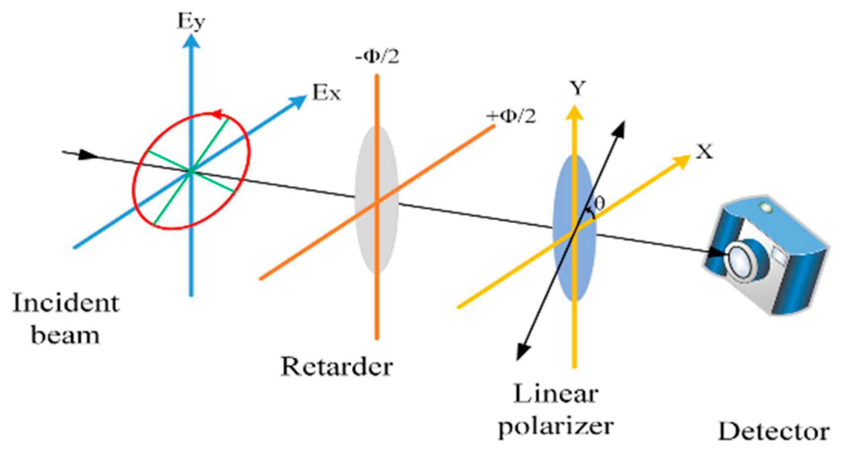
According to the CP characteristics, the CP light can be detected by setting up a measurement system as shown in Figure 4. Two key parts of the measurement system include a retarder and a linear polarizer, as shown in Figure 4. The imaging process of the system can be expressed by the Mueller matrix MR(ϕ, θR, θP) in Equation (3):
M = M R ( ϕ , θ R ) M P ( θ P ) = 1 2 [ 1 0 0 0 0 cos 2 2 θ R + cos ϕ sin 2 2 θ R ( 1 cos ϕ ) × sin 2 θ R cos 2 θ R sin ϕ sin 2 θ R 0 ( 1 cos ϕ ) × sin 2 θ R cos 2 θ R sin 2 2 θ R + cos ϕ cos 2 2 θ R sin ϕ cos 2 θ R 0 sin ϕ sin 2 θ R sin ϕ cos 2 θ R cos ϕ ] [ 1 cos 2 θ p sin 2 θ p 0 cos 2 θ p cos 2 2 θ p sin 2 θ p × cos 2 θ p 0 sin 2 θ p sin 2 θ p × cos 2 θ p sin 2 2 θ p 0 0 0 0 0 ]   ,
where MR(ϕ, θR) and MP(θP) represent the Mueller matrix of the retarder and the linear polarizer at an arbitrary angle, respectively; ϕ is the total phase shift between the two orthogonal components of the incident field; θR denotes the angle between the fast axis of the retarder and x-axis, and; the transmission axis of the polarizer is set at angle θP to the x-axis. During measurement, ϕ is fixed to 90° and θR is set to 45° in order to derive Equation (4). Then, the transformation of CP to LP, its detection by rotating the linear polarizer to change θP, and two states (IB(x, y, θP) and IW(x, y, θ’P)) of the incident light—named the best state and the worst state—are determined [8]. When calculating the airlight IA(x, y), we choose the intensities of areas without any objects in the best state and worst state images and mark them by I ^ B ( x , y , 0 ) and I ^ W ( x , y , 90 ) , respectively. Equation (5) gives the DoCP of the airlight, according to the definition of polarization degree.
I ( x , y , θ p ) = 1 2 [ S 0 ( x , y ) + S 3 ( x , y ) cos ( 2 θ p ) ]   ,
p c = | I ^ B ( x , y , 0 ) I ^ W ( x , y , 90 ) I ^ B ( x , y , 0 ) + I ^ W ( x , y , 90 ) | = | S 3 ( x , y ) S 0 ( x , y ) |   .
As we know, a wavelet transform decomposes an image into low- and high-frequency components, where a low-frequency component denotes the approximation, and a high-frequency component characterizes the details of its last order image. Accordingly, the circular polarization information brought in by the interaction between raindrops and natural light is taken care of in the low-frequency parts [17]. In the captured images, the radiance IT(x, y, λ) received by the detector can be expressed as Equation (6) in the low-spatial frequency parts.
I T ( x , y , λ ) = I D ( x , y , λ ) + I A ( x , y , λ )   ,
where ID(x, y, λ) represents the direct transmission of radiance from the imaged scene; IA(x, y, λ) denotes the radiance of the airlight; IO(x, y, λ) stands for the object radiance in a clear-day image, as shown in Equation (7) [10]. Additionally, t(x, y, λ) = eβz(x,y,λ) means the atmosphere-attenuated coefficient, where β is the scattering coefficient [4]; IA(x, y, λ) is the airlight radiance corresponding to an object at infinity. λ is the wavelength.
I O ( x , y , λ ) = I T ( x , y , λ ) I A ( x , y , λ ) t ( x , y , λ ) = I T ( x , y , λ ) I A ( x , y , λ ) 1 ( I A ( x , y , λ ) / I A ( x , y , λ ) )   .
Two key parameters, IA(x, y, λ) and IA(x, y, λ), should be considered to find IO(x, y, λ). The IA(x, y, λ) can be expressed as IA(x, y, λ) = (S0(x, y, λpc)/pc, where pc is the DoCP corresponding to an object at infinity. Therefore, the core of this open problem is to calculate the intensity of airlight by utilizing the CP characteristics of scattered light. In combination with Equations (5) and (7), the final way to calculate the object radiance in a clear-day image IO(x, y, λ) is expressed by Equation (8).
I O ( x , y , λ ) = p c I T ( x , y , λ ) Δ I ^ ( x , y , λ ) ( 1 t ( x , y , λ ) ) p c t ( x , y , λ )   ,
where Δ I ^ ( x , y , λ ) = (IB(x,y,θP) − IW(x,y,θ’P)). Although the wavelet decomposition enables the image recovery in the low-frequency components, the absolute values of the wavelet coefficients become larger, which would result in a decrease in image clarity in high-spatial frequency regions [10]. Hence, a dual-threshold process algorithm is taken to adjust the high-frequency coefficients, as shown in Equation (9). This can remove the coefficients within a certain threshold range and enhance those outside the threshold range.
W o u t = { W i n + ( T 2 ( G 1 ) ) ( T 1 G ) W i n > T 2 G ( W i n T 1 ) T 1 < W i n < T 2 0 T 1 W i n < T 1 G ( W i n + T 1 ) T 2 W i n < T 1 W i n ( T 2 ( G 1 ) ) + ( T 1 G ) W i n < T 2   ,
where Win and Wout are the wavelet coefficients before and after enhancement transfer, respectively; G is the gain, which is empirically selected within a range in a scene and weather condition; T1 and T2 are two thresholds with T1 < T2, and T1 is determined by the image size n and the variance of the image σ [10]. The coefficients transferred by the function shown in Equation (9) will be adjusted by an appropriate gain to improve the clarity of the images. The appropriate gain is obtained by evaluating the corresponding clear image quality through iterative gain in the range. Therefore, with the separate processing of the low-spatial frequency and high-spatial frequency components, both the clarity and visibility of rainy-day images can be improved.

3. Results and Discussion

To demonstrate the practicability and performance of the proposed method based on the CP characteristics, we conducted several experiments under different weather conditions, and the results were analyzed.

3.1. Effect of Water Spray Removal

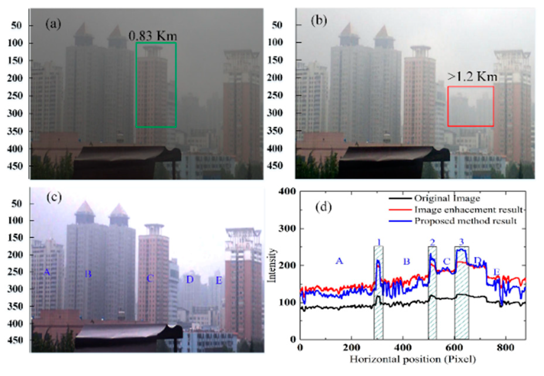
The experimental results for three different scenes are presented in the following discussions, and the corresponding weather conditions are also listed in Table 1. Firstly, using Scene One shown in Figure 5a as an example, this image was taken at the North Gate of Xidian University, Xi’an, with low contrast and weak visibility. After being processed by the image enhancement algorithm in reference [24], in Figure 5b, the outlines of the buildings become more distinct. However, the whole image is still shielded by a piece of gauze due to the scattering effect. In comparison, the image in Figure 5c processed by our method shows enhancement effects in not only contrast but also the details of the image. For instance, the building marked by the red rectangle in Figure 5b is over 1.2 km away from the camera and is hardly visible in Figure 5a,b, while Figure 5c provides a much clearer image of this building as well as the buildings around it. In addition, for the nearby building about 0.83 km away from the camera outlined by a green rectangle in Figure 5a, its contrast is sharply enhanced. Overall, the method proposed in this study works well to improve the contrast of rainy-day images and optimize water spray opaque regions to some extent in rainy-day images.
To demonstrate more quantitative data, a horizontal line of the intensity value versus the horizontal position of the image is plotted in Figure 5. Taking the vertical position of pixel 246 from the top, this horizontal line passes through buildings A, B, C, D, and E labeled in Figure 5c. The three shaded areas labeled by 1, 2, and 3 represent the background between A and B, B and C, and C and D, respectively. The variant trends of the blue and red curves are very similar, but the contrast of the image denoted by the blue curve is superior to that of the red one, which is improved by about 2.6 times. This is due to the removal of water spray scattering effects, which can highlight the buildings out of the background of the sky.
Experimental results for the second scene are exhibited in Figure 6. The original rainy-day image in Figure 6a exhibits low contrast, whereas Figure 6b presents a much better result processed by the proposed method. Detailed improvements can be noticed through the buildings labeled as A, B, and C. Firstly, the definition and visibility are significantly improved. Not only is the building outline much clearer, but also more details (such as floors of the building) emerge in the processed image. Secondly, the horizontal lines of vertical pixels 120 and 85 from the top pass through buildings A, B, and C, and cranes D and E in both the original rainy-day image and the reconstructed image by our method. Areas 1, 3, and 4 marked by the green rectangle clearly highlight the building and cranes A, D, and E in the reconstructed image, respectively. Furthermore, a small distance between buildings B and C is also significantly exhibited by the prominent peak of the red curve in the shaded area 2. As for contrast, the black curve presents a gentle variation trend, while the sharp concave peaks emerge from the red curve. In addition, the tower cranes show in Figure 6e,f also clearly display the changes (from invisible to visible). Compared with the original image, the processed images indeed make it easier to locate targets.

3.2. Color Analysis

One of the most straightforward characteristics of an image is color. In the following parts, the effects of the proposed method are demonstrated on the reconstruction of actual image color. The RGB color space model is chosen. The intensities of each pixel in channels R, G, and B are tallied. Taking Scene One as an example, the statistical results are given in Figure 7. The proposed method in Ref. [24] could improve the image contrast to some extent (Figure 7b), but the improvement in color is limited, since the extension of the intensity statistic distribution is limited, as exhibited in Figure 7e. In comparison, Figure 7f is considerably extended as well as the dynamic range of the image color. The color distribution of the original image ranges from 30 to 120. The clear image by our method is shown in Figure 7f, which has an extended dynamic range from 0 to 255. Additionally, the color distribution of our method is about twice that of Ref. [24].
In addition, Figure 8 presents the results for Scene Three. Figure 8b was processed by the proposed method, displaying higher contrast and a better visual effect than Figure 8a. Additionally, the dynamic range of color is noticeably improved by approximately 2 times that of the original image, indicating much clearer details of the scene.
All the results demonstrate the capabilities of CP imaging technology in the effective reconstruction and correction of color decay brought about by the scattering of water spray, as well as the enhancement of image quality.

4. Conclusions

This study presents a CP imaging method for enhancing the vision in rainy-conditions by combining the multi-scale analysis in the frequency domain. This method can enhance the contrast of rainy-day images and recover image color. It is based upon the interaction between light and water spray including absorbance and scattering. The key step is using the CP memory effect in the low-frequency parts to improve the quality of images in rainy conditions and compensate for the specific structure information by the high-frequency parts. By this method, much clearer images with better image colors can be reconstructed. This processing method provides a new way to remove the influences of water spray on images and enhance visibility on rainy days. For future work, we will extend this method to video monitoring such as a driving safety assistance device.

Author Contributions

Conceptualization, F.L. and X.L.; methodology, F.L. and X.L.; validation, F.L. and P.H.; formal analysis, F.L. and X.S.; resources, F.L. and X.S.; data curation, X.L. and P.H.; writing—original draft preparation, F.L.; writing—review and editing, P.H. and X.L. All authors have read and agreed to the published version of the manuscript.

Funding

This work was supported in part by the National Natural Science Foundation of China, under grant 62075175, 62005203.

Institutional Review Board Statement

Not applicable.

Informed Consent Statement

Not applicable.

Acknowledgments

The authors would like to acknowledge Guo Li from Xidian University for helping to acquire experimental data in this paper. Thanks to Rui Gong from Xidian University, Genny Pang from Stanford University and Mohammad Tahinejad from Georgia Tech. for checking the English grammar of this paper.

Conflicts of Interest

The authors declare no conflict of interest.

References

  1. Ding, Z.; Tang, Q.; Liang, C.-P.; Wu, K.; Sandlerc, A.; Li, H.; Chen, Y. Imaging Spinal Structures with Polarization-Sensitive Optical Coherence Tomography. IEEE Photon J. 2016, 8, 1–8. [Google Scholar] [CrossRef]
  2. Cao, L.; Shao, X.; Liu, F.; Wang, L. Dehazing method through polarimetric imaging and multi-scale analysis. In Proceedings of the Satellite Data Compression, Communications and Processing XI, Baltimore, MD, USA, 21 May 2015; p. 950111. [Google Scholar]
  3. Guan, J.; Zhu, J. Target detection in turbid medium using polarization-based range-gated technology. Opt. Express 2013, 21, 14152–14158. [Google Scholar] [CrossRef] [PubMed]
  4. Schechner, Y.Y.; Narasimhan, S.G.; Nayar, S.K. Polarization-based vision through haze. Appl. Opt. 2003, 42, 511–525. [Google Scholar] [CrossRef] [PubMed]
  5. Ullah, K.; Liu, X.; Xiong, J.; Hao, J.; Xu, B.; Jun, Z.; Liu, W. A polarization parametric method of sensing the scattering signals from a submicron particle. IEEE Photonics Technol. Lett. 2016, 29, 1–4. [Google Scholar]
  6. He, K.M.; Sun, J.; Tang, X.O. Single image haze removal using dark channel prior. IEEE Trans. Pattern Anal. Mach. Intell. 2010, 33, 2341–2353. [Google Scholar] [PubMed]
  7. Yeh, C.-H.; Kang, L.-W.; Lee, M.-S.; Lin, C.-Y. Haze effect removal from image via haze density estimation in optical model. Opt. Express 2013, 21, 27127–27141. [Google Scholar] [CrossRef] [PubMed]
  8. Schechner, Y.; Narasimhan, S.; Nayar, S. Instant dehazing of images using polarization. In Proceedings of the 2001 IEEE Computer Society Conference on Computer Vision and Pattern Recognition CVPR 2001, Kauai, HI, USA, 8–14 December 2001; pp. 325–332. [Google Scholar]
  9. Liang, J.; Ren, L.; Ju, H.; Zhang, W.; Qu, E. Polarimetric dehazing method for dense haze removal based on distribution analysis of angle of polarization. Opt. Express 2015, 23, 26146–26157. [Google Scholar] [CrossRef] [PubMed]
  10. Treibitz, T.; Schechner, Y.Y. Active Polarization Descattering. IEEE Trans. Pattern Anal. Mach. Intell. 2009, 31, 385–399. [Google Scholar] [CrossRef] [PubMed] [Green Version]
  11. Fang, S.; Xia, X.; Huo, X.; Chen, C. Image dehazing using polarization effects of objects and airlight. Opt. Express 2014, 22, 19523–19537. [Google Scholar] [CrossRef] [PubMed]
  12. Liu, F.; Cao, L.; Shao, X.; Han, P.; Bin, X. Polarimetric dehazing utilizing spatial frequency segregation of images. Appl. Opt. 2015, 54, 8116–8122. [Google Scholar] [CrossRef] [PubMed]
  13. Li, X.; Liu, F.; Han, P.; Wei, Y.; Zhao, D.; Shao, X.; Zhao, X. Research on polarization dehazing through the coaxial and multi-aperture polarimetric camera. OSA Contin. 2019, 2, 2369–2380. [Google Scholar] [CrossRef]
  14. Mobley, C.D. Light and Water: Radiative Transfer in Natural Waters; Academic Press: San Diego, CA, USA, 1994. [Google Scholar]
  15. Hansen, J.E.; Travis, L.D. Light scattering in planetary atmospheres. Space Sci. Rev. 1974, 16, 527–610. [Google Scholar] [CrossRef]
  16. Konnen, G.P. Polarized Light in Nature; Cambridge University Press: Cambridge, UK, 1985. [Google Scholar]
  17. Liu, F.; Shao, X.; Xu, J.; Han, P. Design of a circular polarization imager for contrast enhancement in rainy conditions. Appl. Opt. 2016, 55, 9242–9249. [Google Scholar] [CrossRef] [PubMed]
  18. Ishimaru, A.; Jaruwatanadilok, S.; Kuga, Y. Polarized pulse waves in random discrete scatterers. Appl. Opt. 2001, 40, 5495–5502. [Google Scholar] [CrossRef] [PubMed]
  19. Hu, H.; Zhao, L.; Li, X.; Wang, H.; Yang, J.; Li, K.; Liu, T. Polarimetric image recovery in turbid media employing circularly polarized light. Opt. Express 2018, 26, 25047–25059. [Google Scholar] [CrossRef] [PubMed]
  20. Xu, M.; Alfano, R.R. Circular polarization memory of light. Phys. Rev. E 2005, 72, 065601. [Google Scholar] [CrossRef] [PubMed]
  21. Liu, F.; Han, P.; Wei, Y.; Yang, K.; Huang, S.; Li, X.; Zhang, G.; Bai, L.; Shao, X. Deeply seeing through highly turbid water by active polarization imaging. Opt. Lett. 2018, 43, 4903–4906. [Google Scholar] [CrossRef] [PubMed]
  22. Liu, F.; Wei, Y.; Han, P.; Yang, K.; Bai, L.; Shao, X. Polarization-based exploration for clear underwater vision in natural illumination. Opt. Express 2019, 27, 3629–3641. [Google Scholar] [CrossRef] [PubMed]
  23. Han, P.; Liu, F.; Wei, Y.; Shao, X. Optical correlation assists to enhance underwater polarization imaging performance. Opt. Lasers Eng. 2020, 134, 106256. [Google Scholar] [CrossRef]
  24. Narasimhan, S.G.; Nayar, S.K. Contrast restoration of weather degraded images. IEEE Trans. Pattern Anal. Mach. Intell. 2003, 25, 713–724. [Google Scholar] [CrossRef] [Green Version]
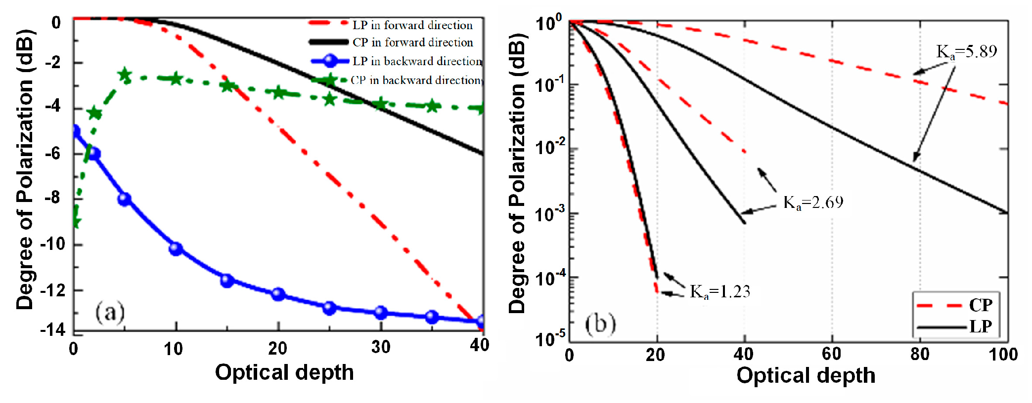
Figure 1. Degree of polarization (DOP) as a function of optical depth in water with different diameter particles; (a) 2 μm particle; (b) the size parameter (ka) varies (Ref. [18]).
Applsci 11 02996 g001
Figure 2. (Top) Light consideration during the circular polarization (CP) detection process in rainy-day conditions. (Bottom) Schematic of natural light’s interaction with rain droplets.
Applsci 11 02996 g002
Figure 3. Paths of light rays scattered by the water droplet according to geometrical optics.
Applsci 11 02996 g003
Figure 4. The measurement diagram of CP states.
Applsci 11 02996 g004
Figure 5. Rainy-day image of Scene One; (a) the original image; (b) the image reconstructed by the image enhancement algorithm [24]; (c) the image reconstructed by the proposed method; (d) horizontal line plot at the vertical position pixel 246 from the top for (ac).
Applsci 11 02996 g005
Figure 6. (a,b): The original image and the reconstructed image. (c,d): Horizontal line plot at the vertical position pixel 120 and 85 from the top for (a,b). (e,f): The enlarged tower cranes part.
Applsci 11 02996 g006
Figure 7. The R, G, and B channel intensity statistics of images in Figure 5. (ac) are the raw image, reconstructed image by Ref. [24], and proposed method; (df) are the channel intensity statistics of the images above.
Applsci 11 02996 g007
Figure 8. The image of Scene Three. (a) The original rainy-day image. (b) The reconstructed image. (c,d) The intensity statistic of each pixel of the original rainy-day image and reconstructed image.
Applsci 11 02996 g008
Table 1. Weather conditions of different scenes.
ParametersScene OneScene TwoScene Three
Temperature (°C)202125
Rainfall capacity (mm/h)1.910.6
Relative humidity99%90%55%
Wind strength (Km/h)51010
Wind directionNorthNorthNorth
Rain levelLight rainLight rainDrizzle
Publisher’s Note: MDPI stays neutral with regard to jurisdictional claims in published maps and institutional affiliations.