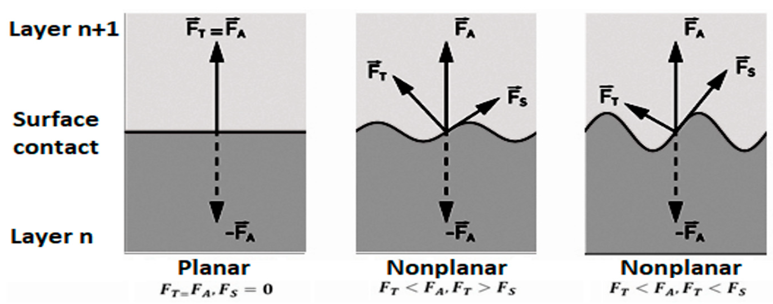
Within the methodology of design of the FDM device design, it is necessary to determine and define its required parameters and purpose. Since the work aims to design the structure focused on innovations and current trends in the industry, one of its priorities is its use. It is well known that recent trends in the use of FDM devices are different. Whether it is the use of printheads installed on robotic arms, or oversized printing used, for example, in construction, the creation of tissue through the layering of biological material, or new materials in this area, the devices used in these areas have one thing in common. They all work on the same principle of layering thermoplastic or other materials in planar layers [
21]. This is based on theoretical assumptions, which form a partial solution related to the design of an atypical structure for FDM technology. Within the publication, we focus on a specific construction type, which we consider to be ideal in several ways. It is well known that compared to serial robots used in conjunction with FDM technology and conventional 3D printer designs, devices based on the principle of parallel manipulators are dominant. Due to their availability, it is relatively simple compared to robotic arms, as well as in regard to speed and dynamic movement. The disadvantage of these devices is their somewhat complicated operation compared to conventional Cartesian-type constructions and the lower achieved accuracy of component production. In the field of parallel manipulators, we know several types of constructions, such as tripod-type manipulators, also used in FDM technology devices, and various other types of constructions based on the parallel motion [
22]. As part of the device’s design, i.e., developing an atypical device, we encounter a combined Cartesian-type construction with an effector characteristic of delta devices. This type of device offers new possibilities in terms of system control and the possibilities of its application. Due to the design and application of the solution to a specific type of atypical production of models, it is necessary to determine the proposed equipment’s basic requirements. Given the knowledge already gained related to structures, control, kinematics and data processing for FDM technology, we can create a list of basic requirements for creating an atypical structure [
23]. These requirements are completed to develop an atypical device designed for non-planar 3D printing. Partial goals are presented, as follows:
2.1. Construction Design Based on Acquired Knowledge
Due to the previous research in types of additive devices, types of their constructions and application solutions, we have arrived at a possible conceptual design of the structure. This construction is to be adapted to the models’ production conditions through non-planar layering of the material. As part of a partial solution, we initially considered a simple alternative to the Tripteron-type construction, which forms a kind of basis for atypical devices with untapped potential. From our perspective, this could be used in the printing of non-planar surfaces [
24].
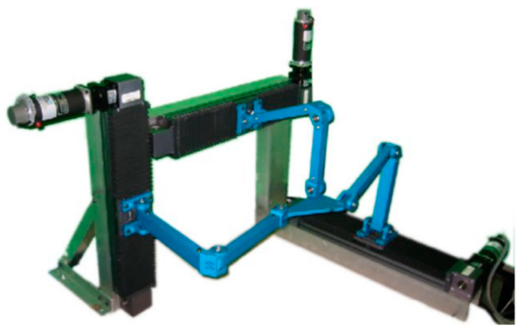
As shown in
Figure 10, constructions of this type are designed to combine Cartesian-type FDM devices. Instead of a standard printhead attached to the X-axis, they have an effector similar to delta-type devices. Given the theoretical knowledge in the field of non-planar layering of material, the key is using an effector connected separately to each of the device axes [
25,
26,
27].
However, during the implementation of this construction, we encountered significant shortcomings. The FDM technology used in the production of key components does not achieve the required accuracy, which would not ensure the system’s sufficient accuracy and rigidity in the case of the used transformation mechanism combining linear guidance and timing belt. The simple forked joints ingested in the joints of the individual arms did not have sufficient rigidity, which in the Z-axis caused the deflection of the entire arm and the subsequent crossing of the linear mechanism. Based on these facts, it was necessary to modify the proposal, which will ensure:
Sufficient rigidity of the system in the Z-axis.
Proper placement of linear guides, guide rods and transformation mechanisms.
Correct position of the effector for the device guides and the printing pad.
Proper placement of sufficient print pads.
Plenty of space for arm movement to prevent collision with the frame when lifting in the Z-axis.
Design of the arms to not collide with the machine frame, the printing pad or other components.
During the FDM device’s design for the production of models by non-planar layering of material, we relied on theoretical knowledge and an overview of the current state. The knowledge was subsequently applied to an existing kinematic model of the Tripteron device. With the help of various types and modifications necessary for realising 3D printing on such a device, this process achieved its design of an atypical construction of an FDM device. As already mentioned, the proposed device has all the characteristic elements of the construction used by additive production devices FDM. Its base is an open “L” shaped frame. It has sufficient space to place the printing plate, lines, drives and other elements [
26,
27,
28].
2.2. Layout Design of the Construction Frame
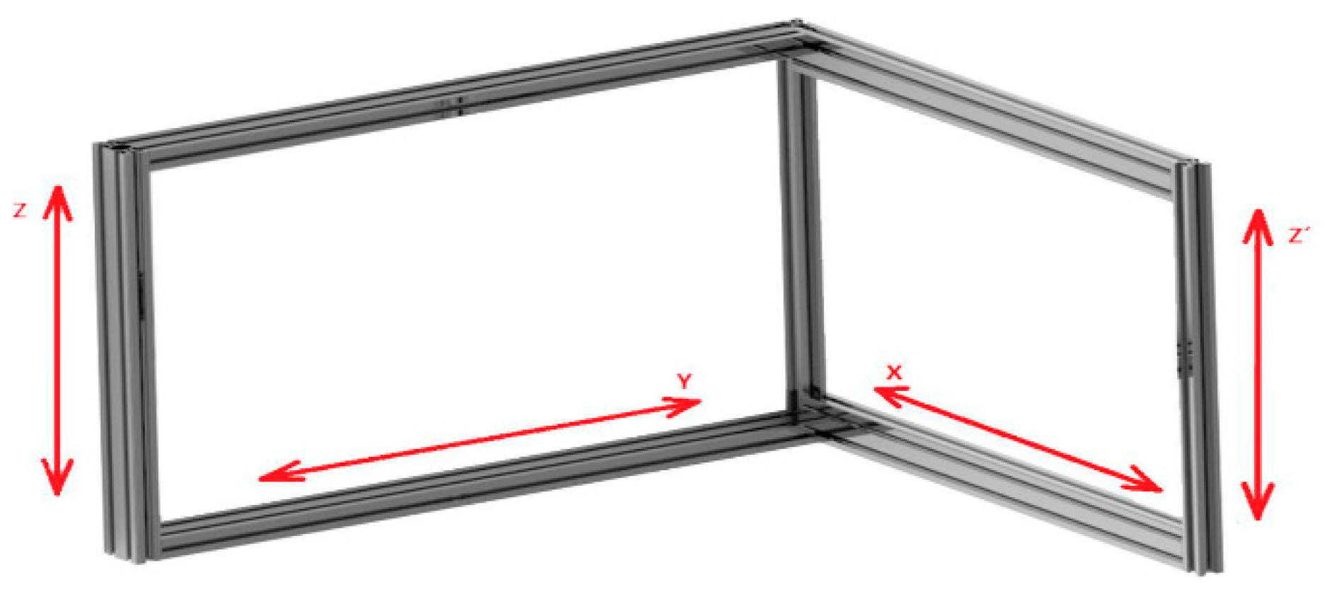
The resulting device concept is designed for non-planar 3D printing, because the conventional design of the FDM device, controlled in three axes, is unsatisfactory in non-planar printing due to insufficient extrusion of the material at an elevation of more than 22.5°. A new concept is proposed for the possible extension, which will allow it to work in more than three axes. It is, therefore, a matter of connecting two types of devices in series. This fact harms the stability of the system, as well as other parameters. For this reason, a frame of a smaller height (
Figure 11), and a larger base, was chosen, which partially eliminates the negative vibrations in the frame caused by the movement of the arms.
The device’s frame is made of aluminium profiles measuring 20 × 20 and 20 × 40 mm. The orientation of these profiles is adapted so that, due to the device’s complicated kinematic, there are no collisions of the arms and carriages in the individual axes, with the frame of the structure (
Table 1). Another influence on the orientation of the profiles is also used by the used connecting parts, i.e., clamps, which ensure the mutual position of individual shapes and ensure the whole frame’s stability.
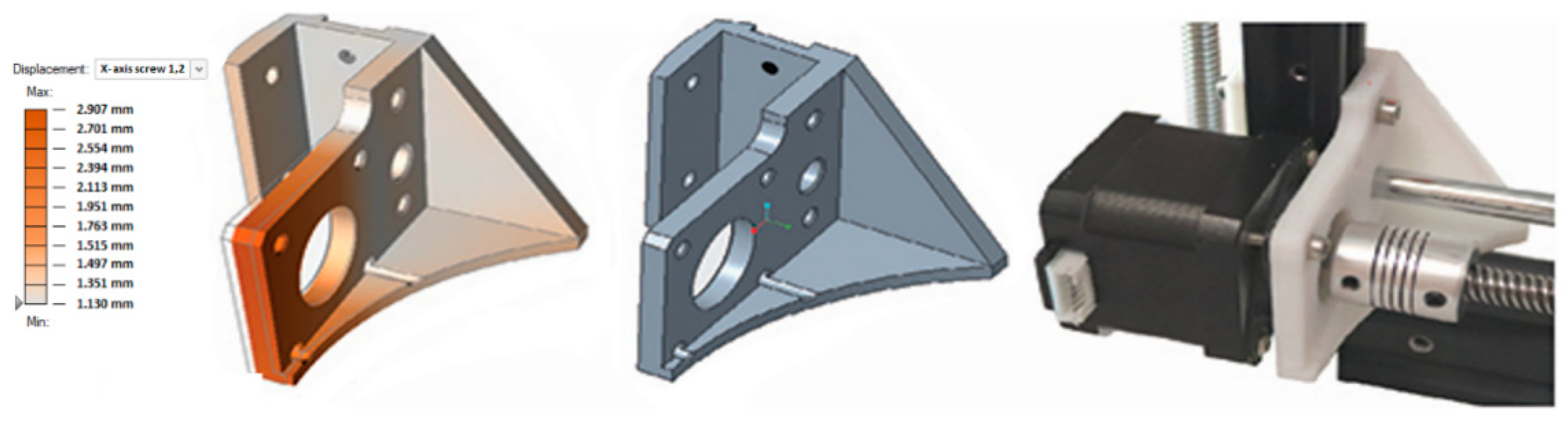
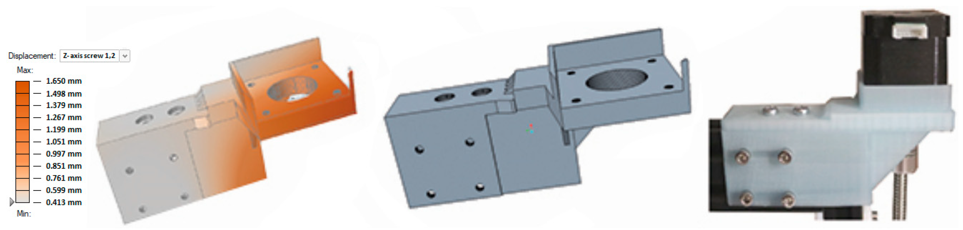
The construction of FDM devices is relatively undemanding. The models have been adapted to be fixed using simple connections of M3 screws and “T” matrix. Various variants of corner brackets served as setting elements for the frame of the structure. The device was designed so that its assembly requires minimal interventions in the frame structure. In connection with the assignment’s solution, a virtual model of the whole assembly and all components was created. The body of the system itself was relatively simple. The use of fasteners and individual elements in a predetermined location on the frame was seamless. The negative factors were the assembly of plastic parts with the help of screw connections, the mechanical properties of the materials used and the deviations of the equipment used to produce components. When mounted on a metal frame, they caused the plastic element to deform. Other negative effects were shown during the commissioning of individual axes. These negative factors, extremely complicating the design of the structure itself, caused the accumulation of large amounts of plastic waste, which resulted in the need to recycle the failures. The critical components were the bearings of motors, drives and lead screws, which can be seen in
Figure 12 and
Figure 13. Modifying these designs using the finite element method greatly accelerated this process and reduced the amount of plastic waste generated, resulting from the high failure.
Due to these deformations, e.g., to offset the guide bar and guide screw. This misalignment was measurable in millimetres, which is unacceptable for the smooth running of the drives and the trolley’s movement with the arm. The misalignment of the lead screw or rod caused an extreme deflection of the flexible coupling, which could not compensate for this deformation. As a result of these shortcomings, the engines overheated, and the truck stopped unintentionally at a greater distance. Due to the dispositional solution of the device frame and the lack of space for alternative possibilities of mutual storage of these subsystems, the need arose on the device to create models common for the storage of components in both axes. As shown in
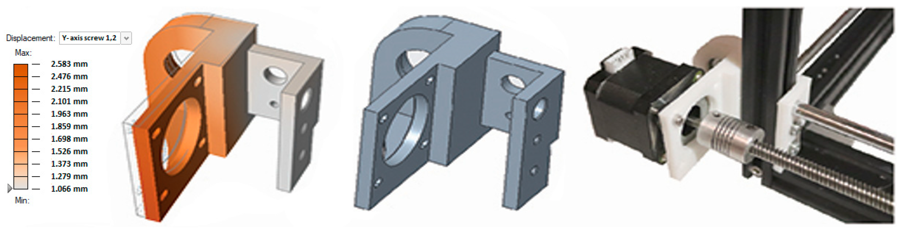
Figure 13, the Y-axis drive mount is also the opposite component for the X-axis bearing, guide screw and guide rod mount.
These defects arose on all key components used to mount drives and linear technology on the device. As a solution to this situation in commercially used FDM devices, applying the so-called free end of lead screws. It means that the end of the lead screw is housed in clearance housing. This play subsequently allows compensation in non-coaxial movement of the lead screw and linear technology, and there is no bending and negative forces. Such a solution is unacceptable due to the nature of our construction. In this case, the loose ends of the guide screws would cause other unwanted vibrations and vibrations of the system, which would negatively affect the prints’ quality. As a solution to these problems, we used the so-called application of the finite element method before the model production process. This solution consisted of analyses of the model’s location within the virtual subsystem and subsequent simulation of the effects acting on individual components [
27,
28]. Individual values of deviations from the initial position can be seen in
Table 2 and
Table 3. Repeated measurements of real models, modifications of CAD models and correction of dimensions and geometry of components were done. In essence, it was a matter of measuring the magnitude of the angular deformation of the drive bearing after fixing the plastic component to the metal frame and comparing it with the simulation. Subsequent deformation was implemented in a CAD model, which served as a template for a new part. This process was applied to each bearing of the drive and the lead screw end element. Gradual measurements and adjustments have succeeded in reducing this negative factor to a minimum, thus ensuring smooth movements in all axes.
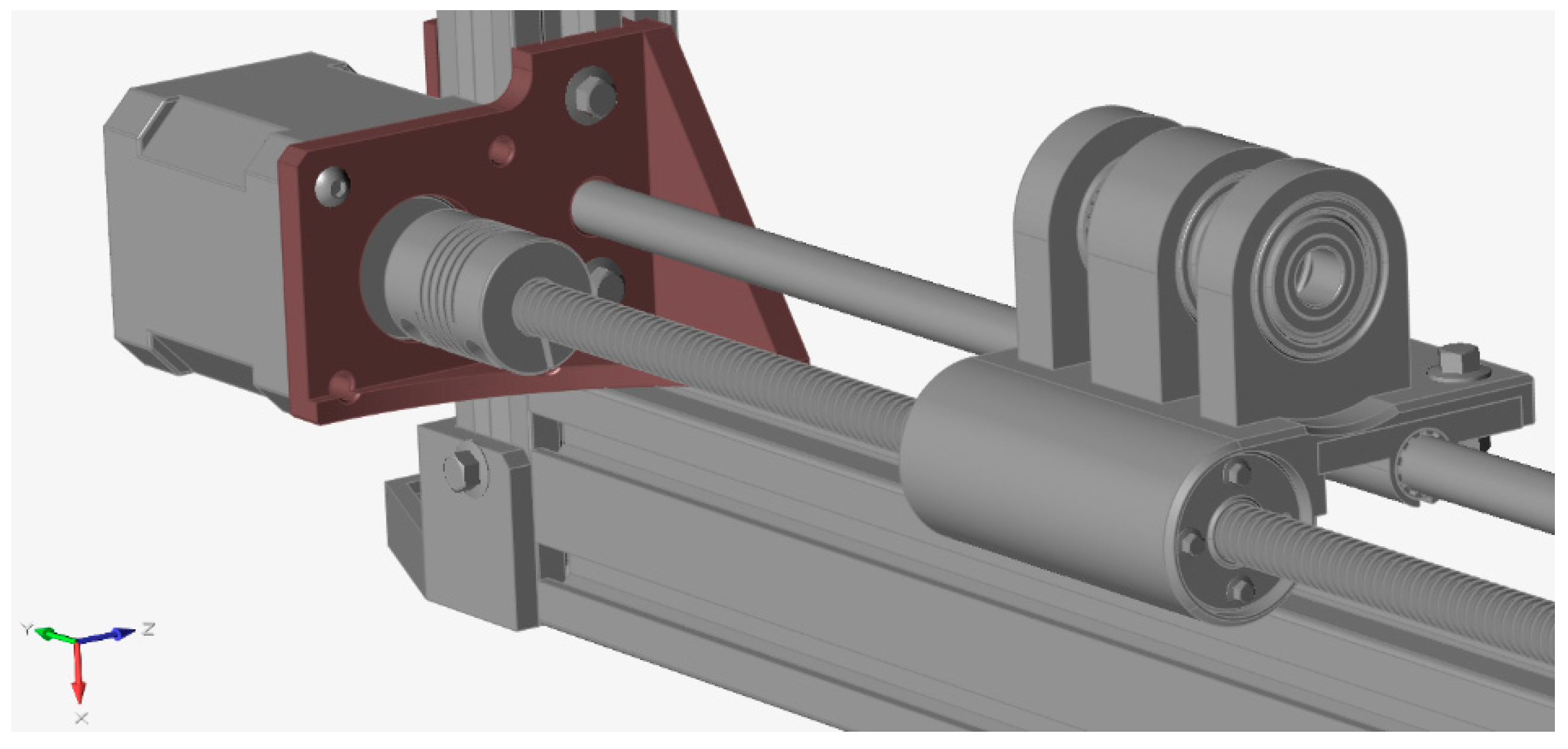
The second problem was the implementation of the shapes of other components in the design of new models. As shown in
Figure 14, the mounting of motors and linear technology often interfered with the proposed models, not excluding the fact that all these models had to correlate with the aluminium profiles and their grooves’ dimensions. This fact required a specific set of the parameters of printing and extrusion of the equipment’s material on which the production of models was carried out. We achieved an ideal material extrusion with the right settings, which allowed us to create components with a non-conflicting shape and the correct dimensions. These components then easily landed in the specified place, in correlation with the developed CAD model.
During the structure’s design process, we did not work only with static models, as was interpreted in the deformation shown in
Figure 12,
Figure 13 and
Figure 14, but we also used the so-called motion analysis. Due to the arms’ arrangement, the types of lines used and the possible negative phenomena resulting from the individual subsystems, the static analysis alone was insufficient. The device is divided into several smaller subsystems, which reduced the time required for each analysis run. One of these subsystems was also the already mentioned X-axis line, together with its key component. The whole part of the construction was used for the simulation itself, as shown in
Figure 15.
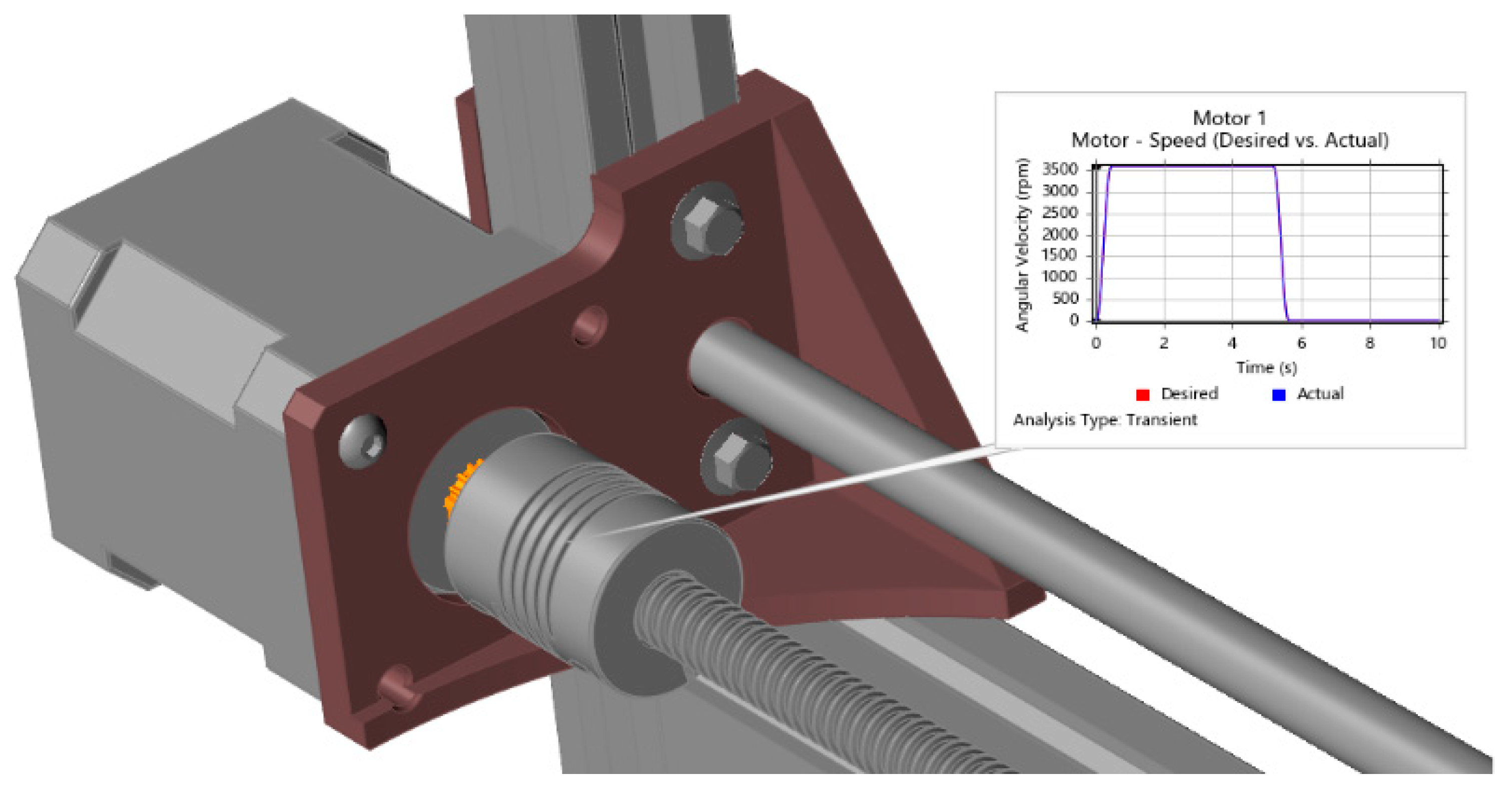
After defining all the connections and supplementing the structural elements such as screw connections and bearings from the library of the used program, the location and type of electric motor used were defined. The advantage of this type of analysis is that it is not necessary to explain all the factors operating on the subsystem. The definition of these factors results from the CAD model itself, the relationships between the individual components, the selected types of materials, etc. The starting curve of the electric motor (
Figure 16) during the analysed load is decisive for us. This was adjusted according to the assumed operating parameters of the proposed FDM device. In
Table 4, we can see the individual parameters defining the course of simulation of the subsystem motion and its analysis.
These operating parameters are unsatisfactory due to the design. An intense increase in the carriage speed in the X-axis causes undesired oscillations between the lead screw and the lead bar, transmitted by the carriage’s work with the arm attached (
Figure 16).
Due to the motion analysis result, we assumed this negative phenomenon at each acceleration, deacceleration or change of the orientation of the print head movement in the X and Y axes. In extreme cases, for example, it manifests itself only by breaking the contact of the print head with the printout. The solution to eliminating this problem was to activate the so-called jerk settings. This function is one of the options related to controlling the speed of the production process implemented in the used software for model preparation. This parameter is also known from the field of machine tools. By activating it, we partially limit the starting speeds to a specific value, from which the speed subsequently increases until it reaches the required operating value. The use of the “jerk setting” function could be explained as follows. If the device has a set maximum speed v = 60 mm/s, and an acceleration a = 20 mm/s2, the device reaches this speed in three jumps in 3 s after start-up. If we set the value “jerk”, or jerks to j = 10 mm/s, we spread the first jump at acceleration and the last at de-acceleration to 2 s. It means a rise from speed from 0 to 10 mm/s and a subsequent increase by leaps according to the corresponding acceleration value up to the required value v = 60 mm/s. This method of eliminating undesired oscillations is suitable as a temporary solution for the production of test specimens.
Due to the excessive scope of applying this method to all components of the device, we list only a few of the most critical ones. By repeatedly combining FEM, measurements and corrections of CAD models, we have achieved the correct placement of each axis and the components stored on it. This correlated with the standard deviation of the equipment on which they were manufactured, i.e., ±0.01 mm. The finite element method allowed us to reduce the plastic waste produced significantly, but dozens of defective pieces were produced despite this reduction. As a result of the increased volume of failures, it was necessary to recycle the waste thus produced.
2.3. Recycling of Plastic Waste from Design
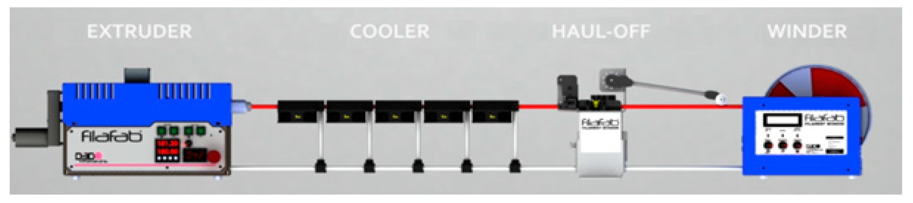
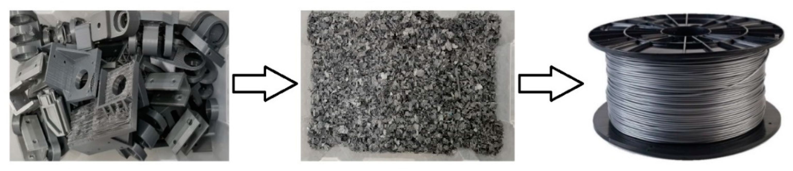
Due to the accumulation of plastic waste and its inherent negative impact on the environment, the recycling of plastics in additive production is necessary. There are currently many studies and publications dealing with this issue. We most often encounter material recycling with conventional FDM equipment. Their simple versions, which have only one print head, produce a relatively large amount of plastic waste, not just in the area of failures. Because the devices use only one type of material in their operation, the material used to support the printing of individual models has a majority share in the production of waste. Equally problematic are the filament residues, which, due to the insufficient volume, have no use in larger components. Due to the waste produced in this way, several devices are used in this technology, which enable the recycling and reuse of material. In a relatively simple cycle, the material is crushed into granules of a specific size, and then this granulate is introduced into a specialised extruder. It works on the principle of a plastic injection chamber, with the difference that the melt is not injected into the mould. The melt passes through a nozzle of a specific diameter and is then cooled and wound on a roll. We schematically see this process shown in
Figure 17.
Due to deficiencies, inaccuracies and various types of external influences, which can significantly affect the production of models using FDM technology, the presentation will always contain a certain percentage of failures. This failure, which is characteristic in particular of the initial stages of prototype production and the changes resulting from there, is predominant in plastic waste generation. Given that this article presents the design and manufacture of atypical FDM equipment, it is obvious that it was necessary to address this issue during its production. The application of the finite element method (FEM) technology in designing key components has partially reduced this failure. Nevertheless, due to the inaccuracies and deviations of the FDM devices, the problem of storing the different types of materials used, and the mechanical properties of the prints themselves, this design did not go without plastic waste accumulation. Due to this fact and the amount of waste produced, the recycling of the produced plastic waste was implemented in this activity. The design has also been extended to include a separate printhead concept, designed to work directly with recycled granulate. The recycling of waste from FDM production and industry as such is of interest to many studies. The issue of partial recovery of waste from individual sectors is also addressed in the publication “Evaluation of the Circularity of Recycled PLA Filaments for 3D Printers” [
30]. The subject of this publication is the use of plastic impact from various industries in a predefined ratio. At the same time, it points out the importance and method of circulation of these materials in production (
Figure 18).
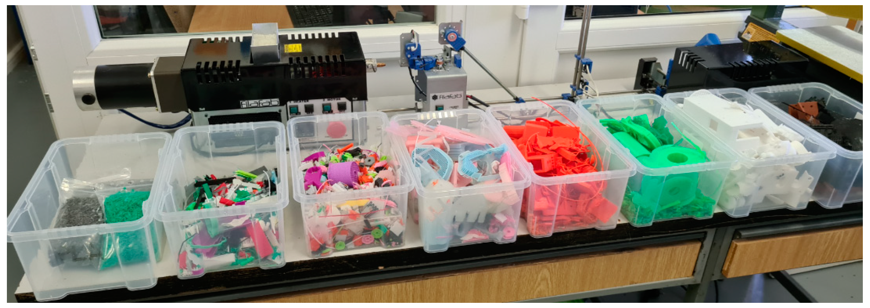
The overall recycling process is not complicated. Essentially, plastic failures, filament residues and supporting material are crushed into granules. It is then processed by a device working on the principle of plastic injection. The difference is that instead of injecting the melt into the mold, the filament is extruded through a nozzle of the desired diameter, the filament is cooled and then wound on a roll. Thanks to this process, it is possible to recycle most of the plastic waste produced. At present, however, this step is beginning to seem redundant, especially in the piece or small series production area. Implementing the granulate processing mechanism into the printhead itself will allow us to reduce these steps with a low degree of production load. As can be seen in the publication “Towards Distributed Recycling with Additive Manufacturing of PET Flake Feedstocks” [
31]. The extrusion system works on the principle of two differently oriented screws, which are used to move the granulate through the print head. By applying heat and pressure in different areas, the melt reaches a state that is identical to the fibre state during the extrusion of the filament by a conventional printhead. As already mentioned, the combination of the finite element method used, measurements, repeated correction of CAD models and subsequent printing caused the accumulation of unnecessary waste during the atypical structure’s prototyping. In combination with the so-called common waste from FDM production, such as excess support, cuttings and ends of filaments significantly affect the direction of the design of the structure (
Figure 19). In the beginning, the excess and non-gift material was recycled and processed into a filament. This process has proven efficient but relatively lengthy and inefficient due to the production batch [
32,
33].
Due to this fact, the design was extended by the creation of an effector with a separate extrusion mechanism integrated directly into it. The print head designed in this way will then allow us to skip some of the steps necessarily associated with recycling. We also consider it another of the necessary steps to improving the state of long-term sustainable development in connection with this type of technology.
2.4. Guide Design in Y and X Axes
Each functional structure must have suitable lines, drives and transformation mechanisms. Due to the creation of the system, which is formed by the series connection of two instruments, the work pays increased attention to lines and transformation mechanisms. It is known that most commonly available FDM devices work with extreme clearances [
34]. This includes e.g., free ends of the lead screws in the Z-axis, which are also visible, e.g., on Zmorph SX or Creality CR-Max devices. These are considered upper and middle class in terms of price and quality of available FDM equipment. A frequent recommendation of these devices’ intermediaries is not to tighten the screw connections to the stop. This fact, combined with the mechanisms’ serial involvement, played an important role in the design.
By successive selection, we have eliminated the conventional mechanisms used to move the FDM device’s components. Due to previous experience and the device’s conceptual design, instruments with V-shaped wheels and timing belts have been excluded. When moving, the mechanism controlled by the timing belts was unsatisfactory. They often wear out and loosen, resulting in inaccurate movement of the arms. This can lead to a collision or damage to the effector. The mechanism moving using rubber wheels in the shape of a “V” has been eliminated due to the frequent loosening of eccentric nuts, which subsequently cause a change in the components’ position. In the case of the series connection of the newly designed structure’s arms, this fact would lead to the accumulation of negative forces caused by the truck’s incorrect position relative to the machine coordination system. The deflection of these arms would subsequently cause the linear guide and the lead screw to cross, thus preventing the carriage from moving and damaging the drive. As part of our proposal, we chose two variants of the solution applied to the XY and ZZ′- axes. The first variant is a combination of a guide rod and a guide screw.
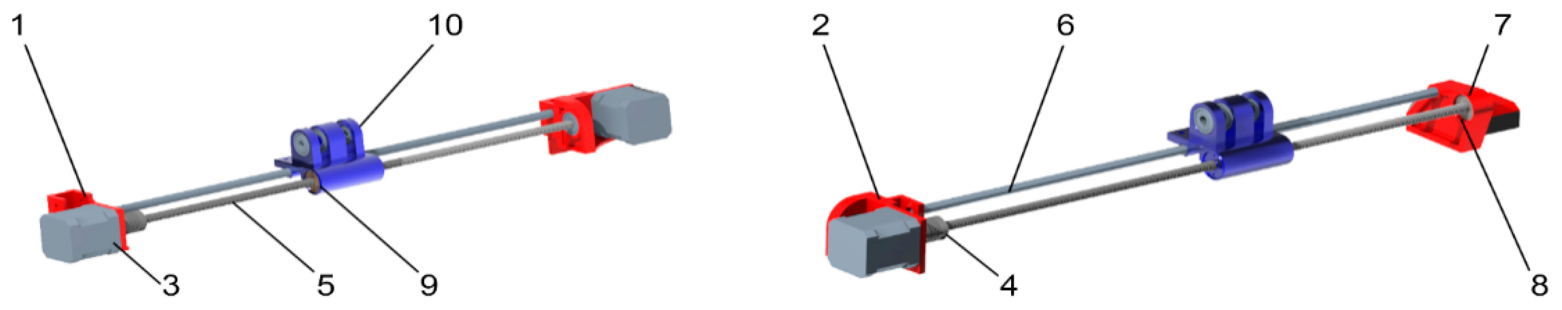
The lines of the devices in the X and Y axes are essentially identical (
Figure 20). The drive of the entire line is provided by the Nema 17 motor (3), which is connected to the lead screw (5) using flexible coupling (4). The carriage movement (10) is ensured through a guide screw and a nut (9) which drives the carriage in the Z-axis. A guide rod’s combination provides its exact position with a diameter of 8 mm (6) with a linear ball bearing (8). The linear bearing and guide nut are housed in the carriage, ensuring the transmission of the guide movements to the first stage of the arm in the Y-axis and its correct orientation for the device’s coordination system.
The line used in the X-axis is similar to the first line. The elements of its construction and the principle of operation remain unchanged. The only change is component No. 2. This key component, which is common to the X-axis and Y-axis, secures the motor’s position in the Y-axis. These components ensured the relative place of the drives, transformation mechanisms and lines. Since these components were to be created using FDM technology as part of the conceptual solution, their production was accompanied by the already mentioned complications and the need for frequent model modifications.
2.6. Design of the X, Y and Z-Axis Arm System
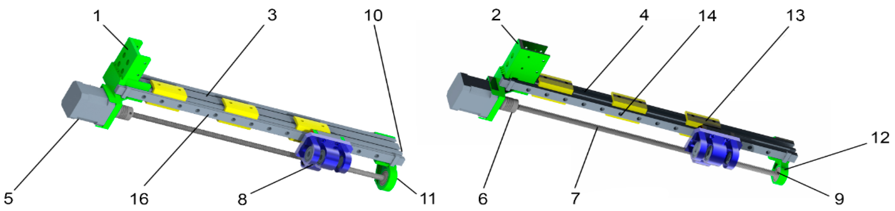
Due to the complicated solution associated with the series connection of the individual elements of the four arms located on the device. It was necessary to pay increased attention to the so-called “Trolleys” moving along a guide bar and a linear guide. They are based on a solid trolley in which all the necessary components are stored. In the case of carriages in the X and Y axes, these components include bearings of type 608 2Z (1), which are used to support the 1st stage arm (
Figure 22). They also participate in its rotational motion. The construction has two components, which required increased attention in terms of their relative position and coaxial. These components, i.e., the linear ball bearing (4) and the guide nut (2), are fastened to the carriage body through screw connections (5 and 3). In the case of a linear bearing, the screw connection is realised on the housing (8) in which the bearing is located.
Figure 22b shows the “trolley” of the Z and Z’- axes. Its design was modified due to the need to reduce the weight of the whole mechanism. The difference is also anchoring on the linear guide realized through M3 screws (5). The change in the type of line was necessary due to the increase required in the system’s stability and rigidity in the Z-axis, which supports the effector’s entire weight.
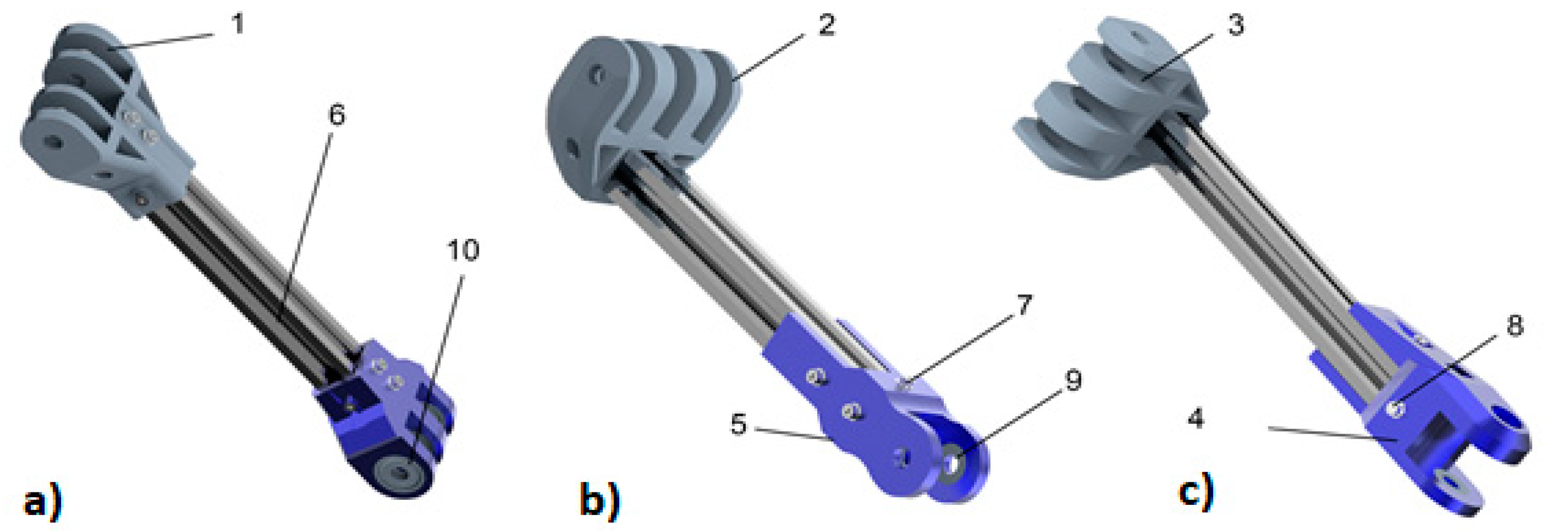
The arm of the first stage of the proposed construction consists of a ridge hinge (1), fixed to the carriage through a screw and a nut M8 and six corresponding washers (
Figure 23a). The arm further consists of a 20 × 20 mm aluminium profile (6), screws (7), washers (8) and “T” shaped nuts ensuring the position and stability of both end elements. The arm’s opposite side is formed by a hinge (10) with bearings that allow arm 2. The second component of the arm in the X and Y axes is the second stage arm (
Figure 23b).
This arm provides the connection of the first arm to the effector. The method of interconnection and transformation of motion is the same as in the previous step. It means that the component has a comb hinge, this time rotated by 90° (2), and an aluminium profile with a 20 × 20 mm diameter, which is connected to the effector holder (7). It is attached to the aluminium frame through screw connections consisting of a screw (7), a washer (8) and a “T” shaped nut. The different shape of the end component is adapted so that it does not collide with the effector through which M8 threaded screws connect it during the movement of the arms in the X and Y- axes. The correct position of the screw connection and the bearings’ trouble-free movement is ensured through washers (9).
As for the connecting element, trolley in Z and Z′ axes, its design is smaller and more compact, as shown in
Figure 23c. It is a more compact design due to the heavier weight of the linear guide housing, which the drive must handle during the device’s operation. The components of these structural elements are similar. Here is a ball bearing, which was replaced by a linear guide house. The trolley is attached to it through M3 screws (4). Other elements of this construction are bearings type 608 2Z, which are used to fasten the arm’s first stage using a screw and nut with an M8 thread. The last element is the guide nut (3), which ensures, as with other components, the transformation of the rotational movement of the guide screw into a sliding movement of the house along with the linear guide. The lead nut is attached to the component with M4 screws (5). The arm’s second stage in the Z and Z′ axes is substantially identical to the X and Y-axes arm. The only difference is the different orientation of the swivel joint connecting the arm to the effector. This component’s shape is then adapted so that it does not collide anywhere with the effector or other arms during movement.
2.7. Design of Other Components of The Structure
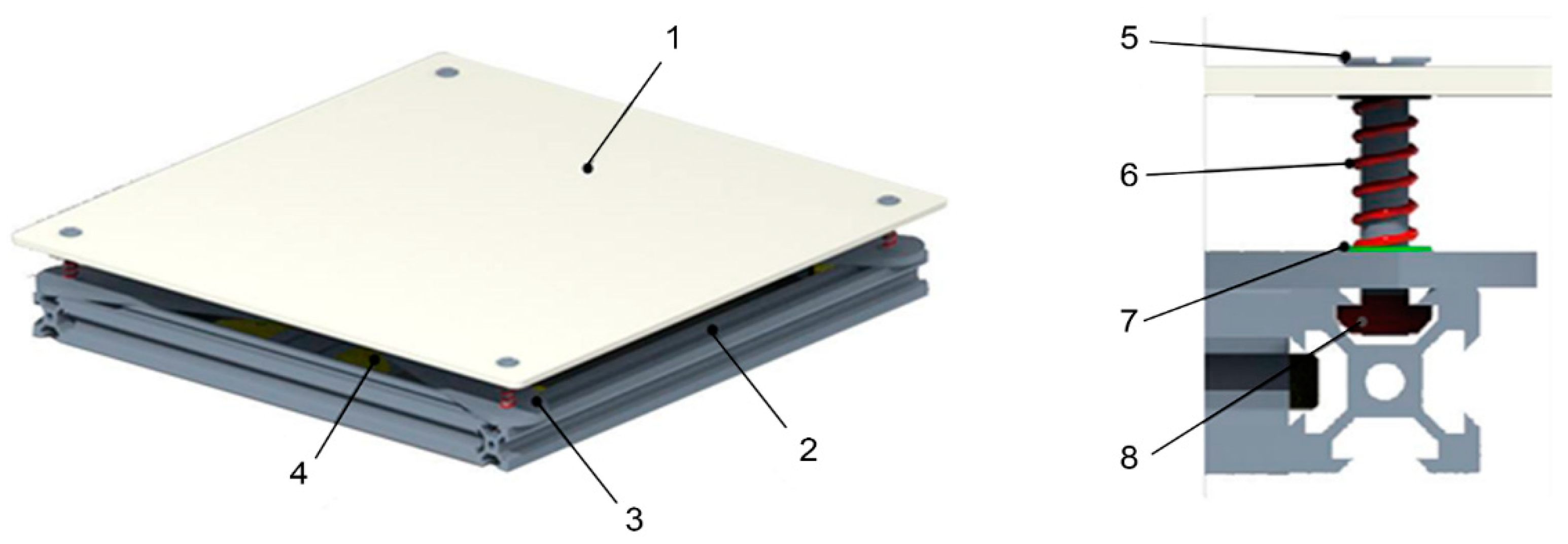
Based on a theoretical analysis dealing with FDM technology, we know that key components characterize each device’s design. In our case, the following features are the effector with the print head, the Bowden extrusion system and the print pad. The design of the printing pad is based on knowledge from the field of FDM technology. The designed printing pad has a relatively simple manual positioning system (
Figure 24). This is based on the principle of tightening the screw (5) and the “T” nut (8) located at the top of the printing pad (1). By turning the screw, we derive the pressing force, which moves one of the corners of the printing pad downwards or upwards when it is released. By positioning each corner of the pad in this way, we then achieve the base’s correct position for the printing process. Due to the series-connected design used and the fact that our proposed solution is based on the principle of a kinematic model that has not yet been tested, it was not our intention to complicate the solution using automatic calibration tools. Their simple design and the principle of operation were based on averaging the position of the limit switch during calibration. In the case of larger deviations, it would average a value higher than the layer’s height during printing. This fact could cause insufficient or no adhesion of the material to the printing substrate in this design.
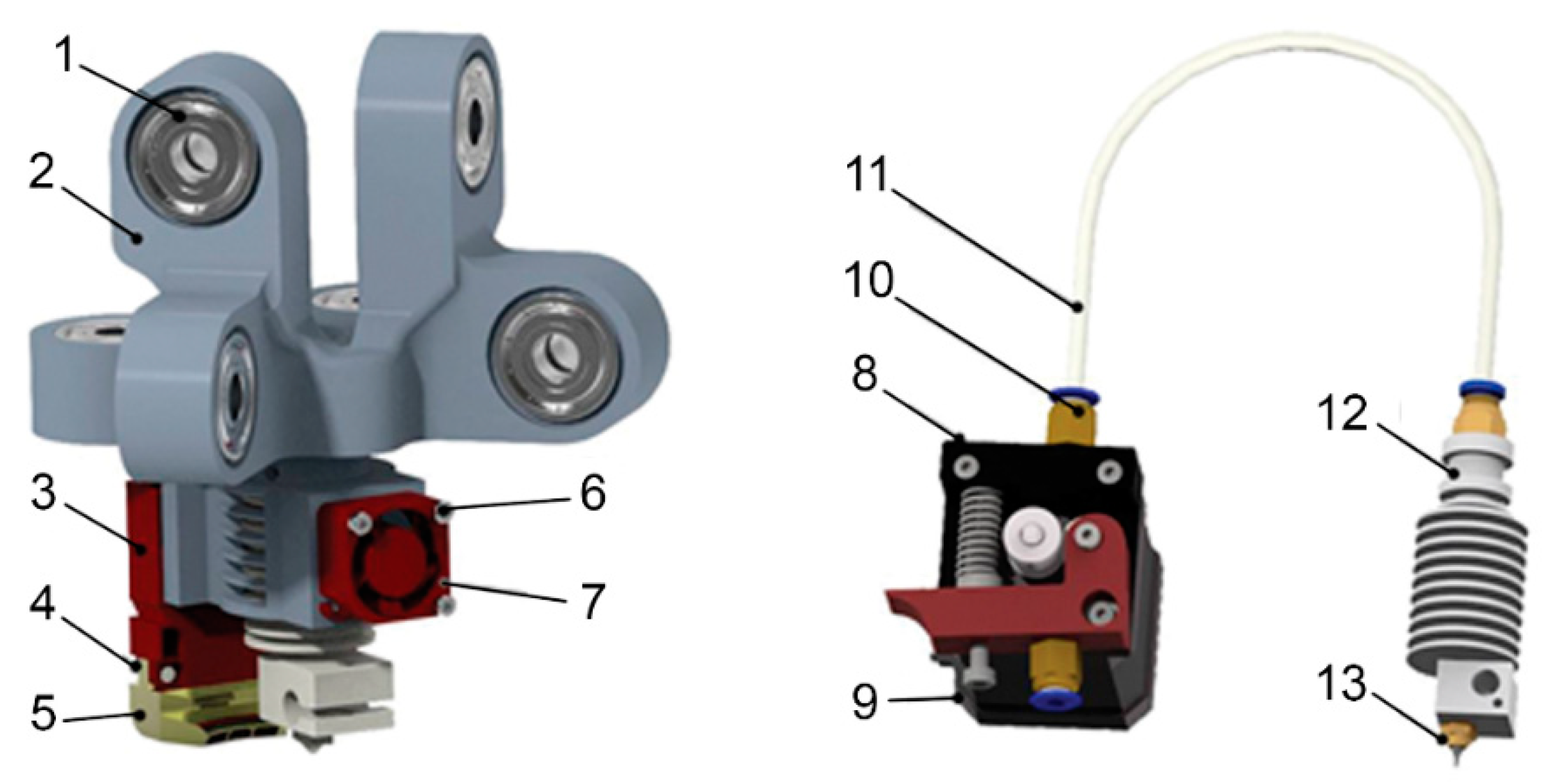
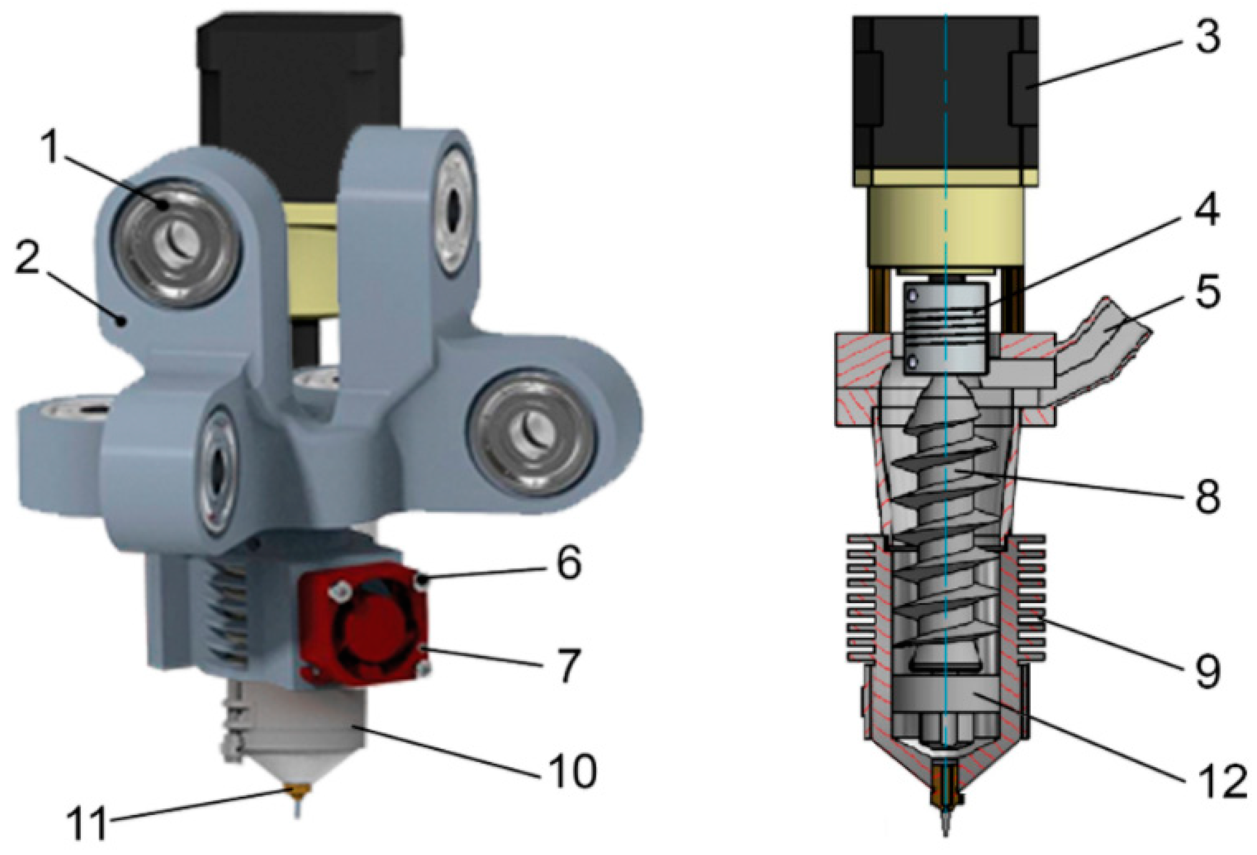
The conclusion of the design is conceptual solutions of the effector and the system for material extrusion. These devices form one unit and are located at the end of the X, Y, Z and Z′ axes. The effector has six joints for the joints, which were created to verify the kinematics of the six-axis device and as support elements that would be needed when using aluminium profiles in the arms and to verify the kinematic model and possible collisions. A Bowden material extrusion system was chosen in the design to reduce the weight of the effector. It is basically a standard system with commonly available components. It is based on the Nema 17 (9) drive, which ensures the fibre’s extrusion. Extruder design that provides the pressure required to extrude the material (
Figure 25). The material is moved through a pneumatic coupling (10) in which a PTFE tube (11) is fixed from the extruder. Inside, the material slides toward the print head (12). There it is heated to the desired temperature and is subsequently extruded in the form of a molten fiber through a nozzle (13). An atypical nozzle was chosen for the design, which will allow the creation of non-planar surfaces on a larger scale. The effector (2), i.e., a key component of the proposed device, consists of bearings. A movable joint is formed between the effector and the end element of the arms X and Y of the second stage after the screw connection has been formed. The bearings are positioned within the effector so that their axis is always parallel to the axis of the lead screw of the respective axis. Other elements of this printing set are fans used as standard. A 20 × 20 × 10 mm centrifugal fan (7) for cooling the passive cooling of the print head and a 40 × 40 × 10 mm axial fan (3) for cooling the layer of material on the printing pad. Both of these components are fixed to the effector body through standard screws (4, 6). The last component of this assembly is the blower used to direct the airflow under the nozzle.
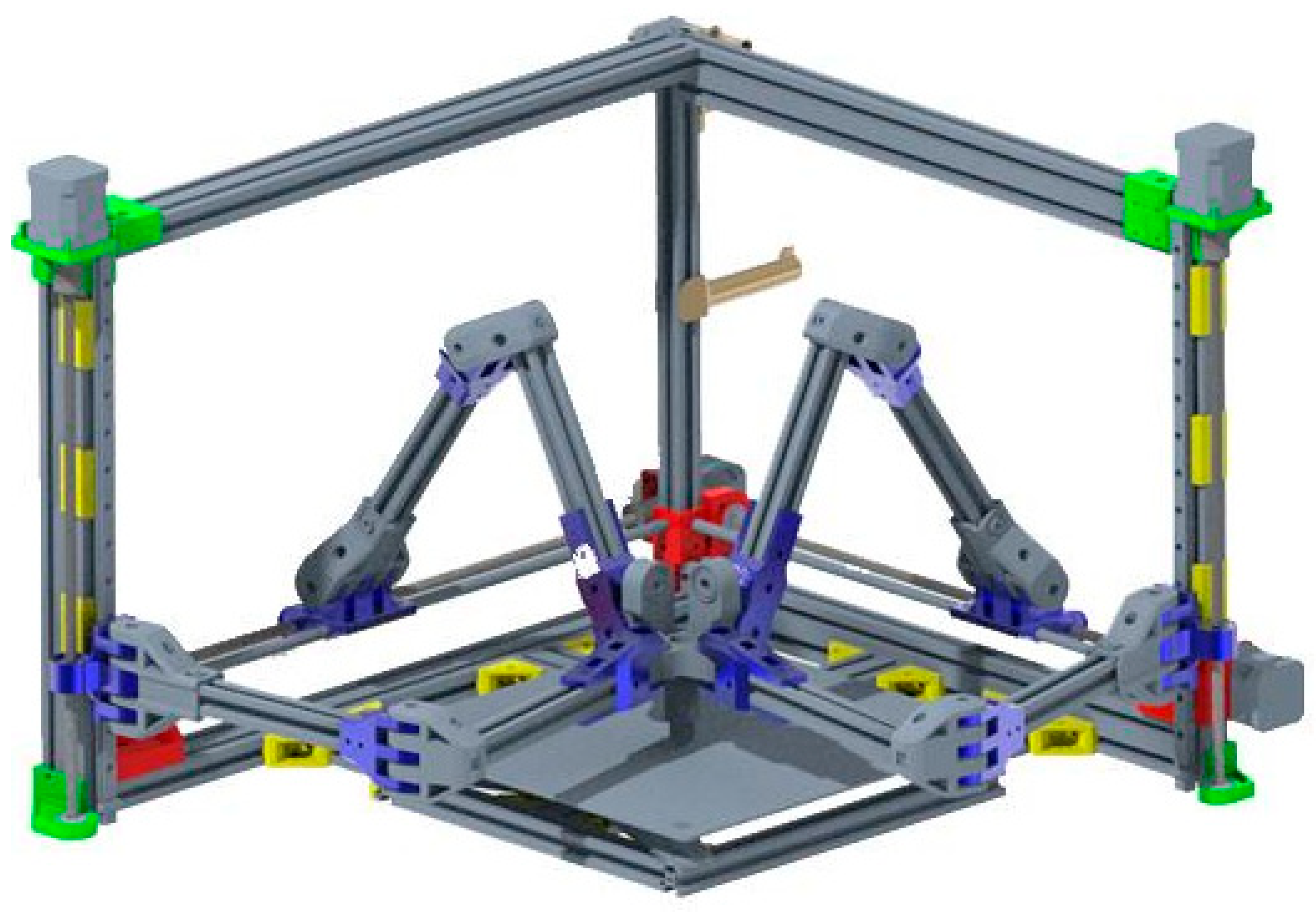
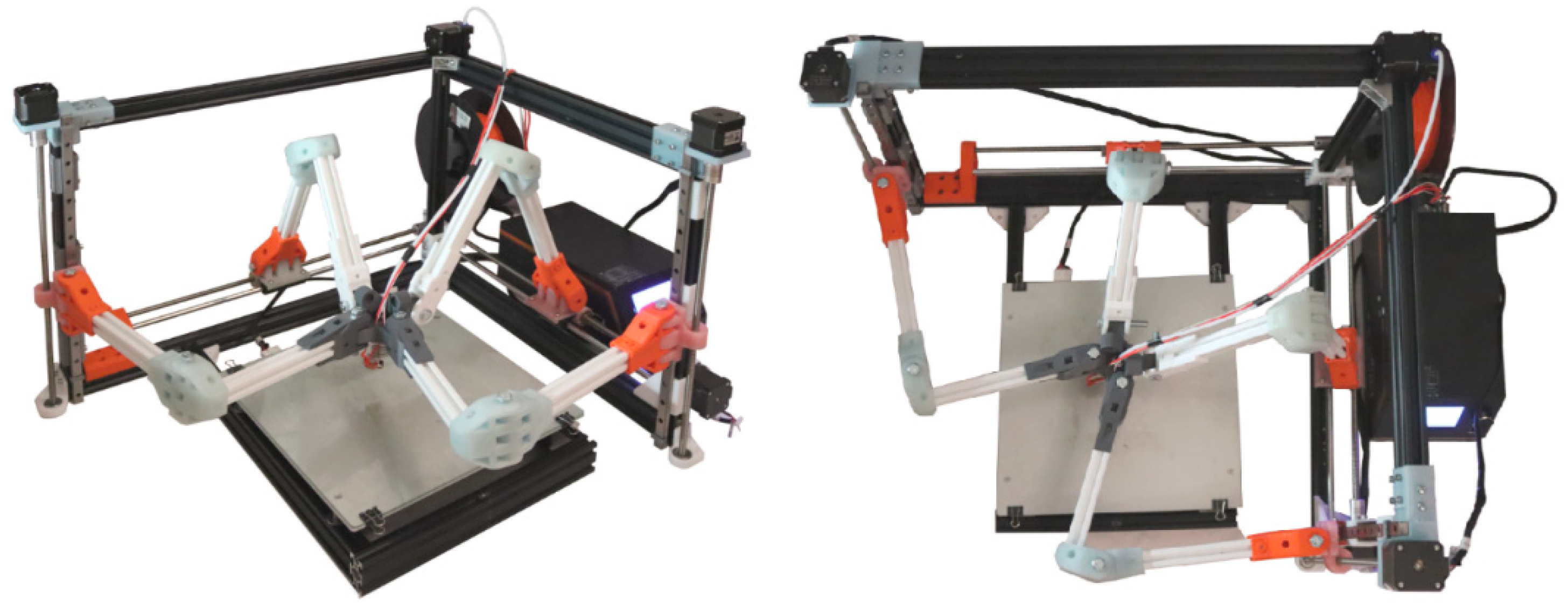
The application of theoretical knowledge to designing a device for printing non-planar surfaces can be seen in
Figure 26. The resulting device consists of two pairs of identical arms that connect the individual axes with the end effector. The base frame is made of aluminium profiles measuring 20 × 20 and 20 × 40 mm. Its L-shaped arrangement has enough space for the movement of all four arms. The design consists of two types of guides, and the first is located in the X and Y axes, is based on the principle of a combination of a lead screw, nut and lead bar. The guides in the Z and Z′ axes consist of linear guides and lead screws with nuts. These guides and transformation mechanisms provide the system with sufficient rigidity and fluidity of movement.
The result of the use of FEM can be seen in
Figure 26. A fully functional FDM device has all the relevant components characteristic of FDM technology. The end effector allows the storage of a tip-shaped print head adapted for the non-planar surface production process. Its movement is ensured by the transmission of the carriages’ sliding movement in the X, Y, Z and Z′ axes through arms. This movement is derived from the rotational movement of the Nema 17 motors and its transformation into a rectilinear sliding motion through a lead screw and a nut. The implementation of the proposal itself consisted of several steps. The first step was to create a request based on the theoretical knowledge gained in the previous chapters. The design (
Figure 27) was created to apply theoretical knowledge and design requirements for the printing of non-planar surfaces. The result of this creative activity was a conceptual design of a device working in three axes. However, this original concept did not have good features. We created the prototype of the atypical FDM device presented in the article. The existing type of Tripteron construction inspires the design of the device. The main purpose and reason for the creation of this construction are the intention to move in the field of this technology towards the development of equipment, which allows the production of prints created by a non-planar method. We consider this type of construction to be ideal for many reasons. One of them is the possibility of expanding the number of axes and drives in these constructions, which subsequently allows active tilting of the effector. We consider this fact to be one of the unique advantages of the chosen structure. For this reason, a new, conceptual version of the device has been created. Due to the continuity and ideology of the RepRap project, the structure’s individual components were designed so that they can be manufactured using FDM technology. The third step was the procurement of elements characteristic of FDM devices, fasteners and subsequent structure implementation.
The presented construction of a prototype FDM device is characterised by a combination of characteristic elements of several devices connected in series. Due to this fact, we tried to adapt the operating parameters for the test samples as much as possible to commercially available FDM equipment. The print settings for printing test samples can be seen in
Table 5.
In terms of accuracy and speed of production of this device, it was initially our intention to approach commercially available FDM devices. However, because this is a prototype, the construction of a combination of two devices connected in series, we initially expected and observed a significant deterioration of accuracy. Our next intention was the gradual identification and elimination of these shortcomings. The operating parameters of the device with which it can operate in the current state are identical to the device settings when printing test samples.
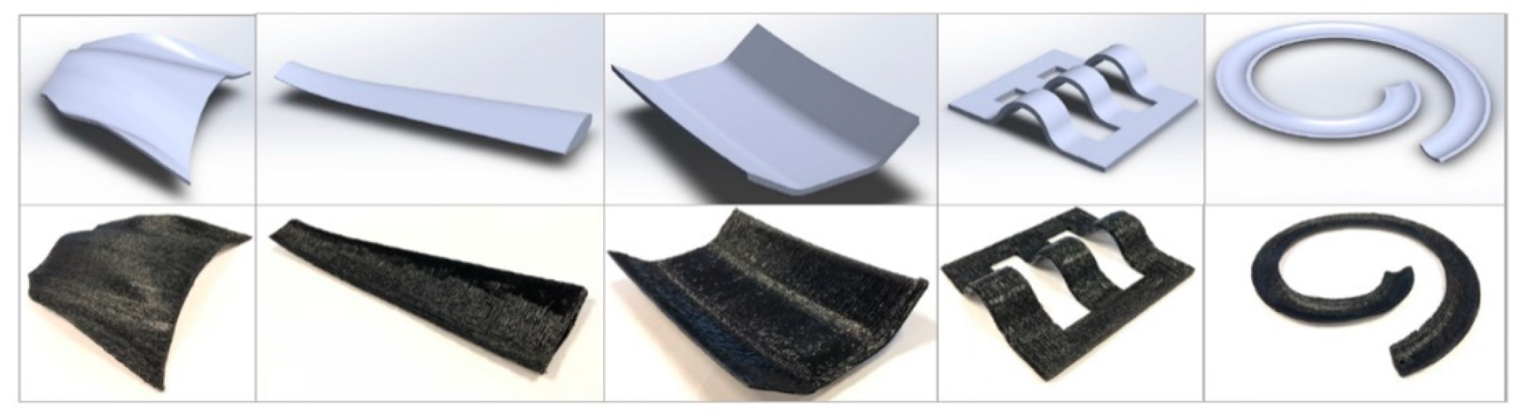
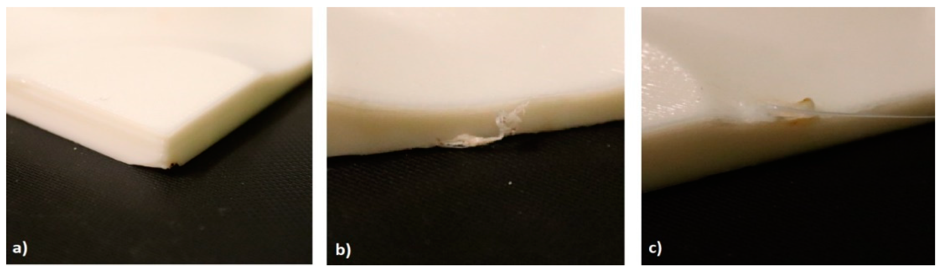
As already mentioned, due to the selected operating parameter and the device’s design character, we observed the common types of defects (
Figure 28).
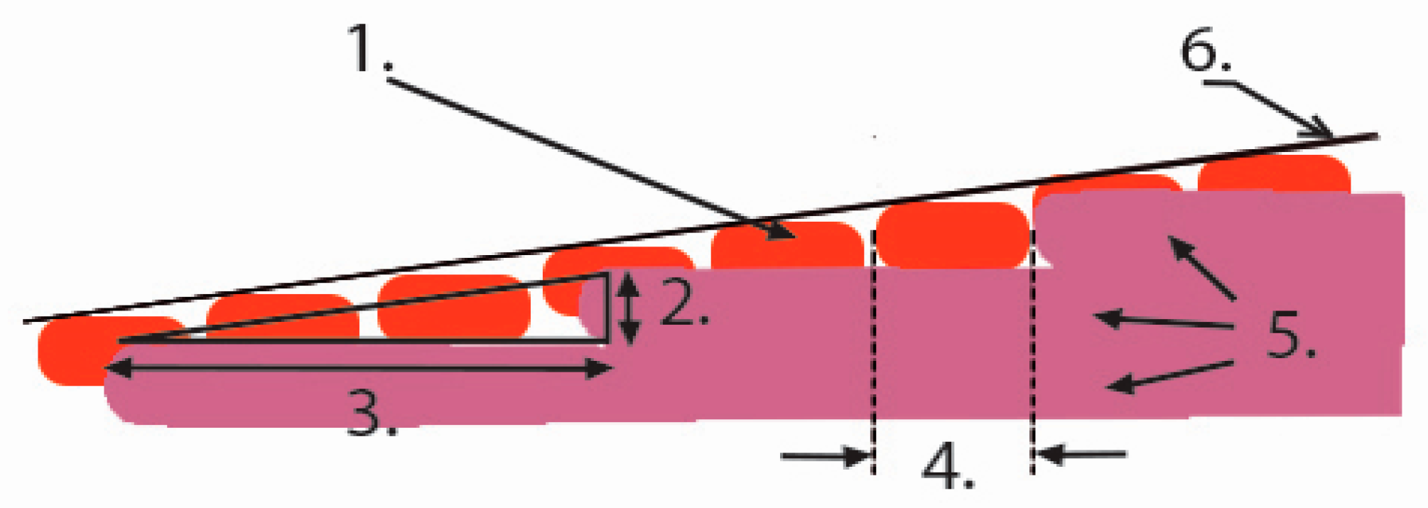
Among the most problematic were:
Incorrect positioning/position of linear technology and transformation mechanisms.
Oscillations of the system during acceleration and de-acceleration.
Deflection occurring at the end of the arms with the effector.
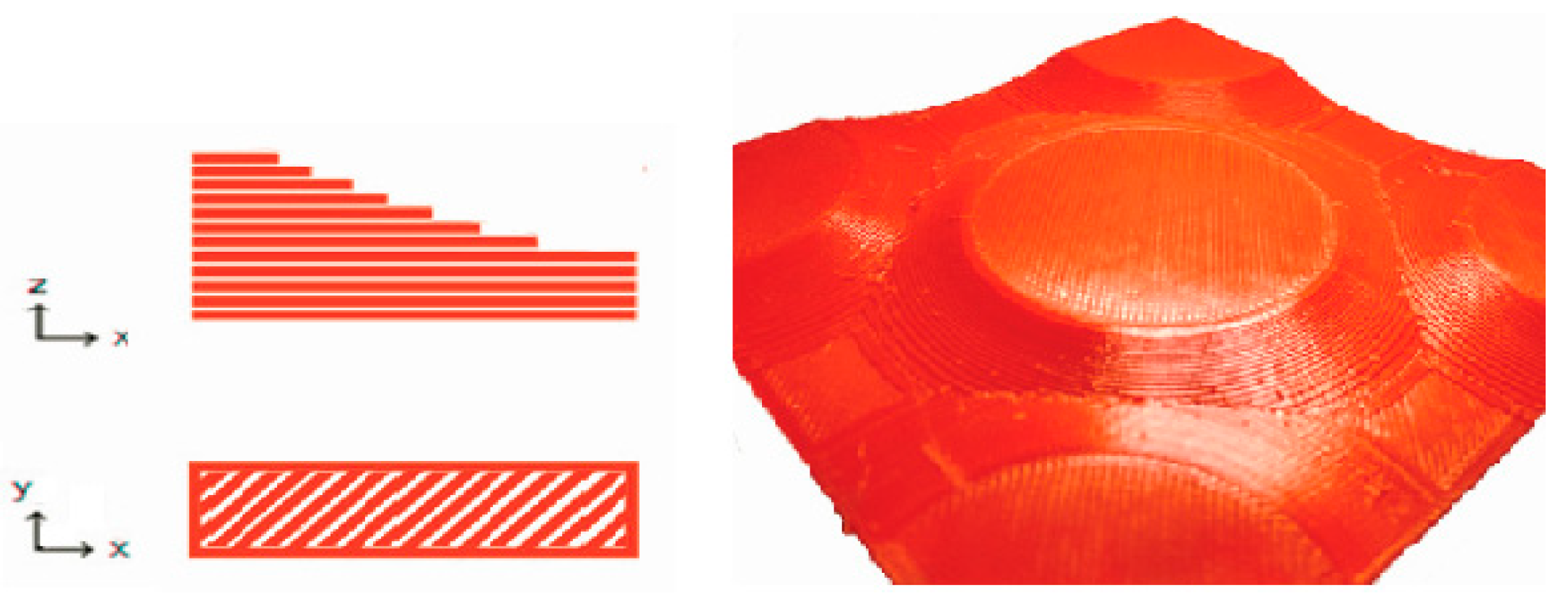
In
Figure 28 it can see the selection with several shortcomings caused by the negative effects. As shown in the figure, the main negative of the construction is the poor adhesion of the layers. It causes incorrect adhesion of the material to the printing pad (
Figure 28a), defects in the individual layers (
Figure 28b), or sealing of the print head to the model (Fiuure 28c). All these shortcomings can be attributed to the arm system’s undesirable vibration, which proved to be the majority problem in the solution.
Minor defects and shortcomings are characteristic of all FDM devices. There are a relatively large number of technological and other factors that can affect the final quality of prints, whether with conventional or atypical FDM equipment. In this case, however, it is possible to observe a majority of defects caused by poor adhesion in the layers. These errors are found throughout the test sample at specific locations. These places are characterised by the fact that the individual circumferential perimeters begin and end in them. It is well known that these places are critical in conventional planar printing. For example, samples used for mechanical tensile testing, produced on FDM equipment, accumulate defects, especially in this area, which leads to undesired weakening of the samples at specific locations. We attribute this undesirable accumulation of defects and their majority representation to the unwanted oscillating system of arms, resulting from the will and minor inaccuracies in the design. This undesired oscillation is reduced in the design by flexible couplings located between the drive motors and the lead screws, changing the starting speeds for the perimeter perimeters and installing dampers on the NEMA17 stepper motors. Despite this step, however, undesired oscillations occur. For this reason, in another area of research, we will focus on changing the design of subsystems providing transformation and transmission of motion on individual axes of the device.
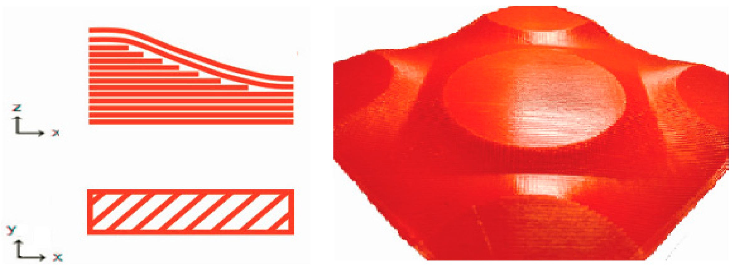
Despite these visible shortcomings, measures were taken in Simplify3D to allow the creation of a non-planar sample. Based on it, we were able to analyse the device’s current state and the impact of its shortcomings on the quality of prints. In
Figure 28, we can see the selection with several defects caused by negative effects. The main negative of the construction, as shown in
Figure 28, the adhesion of the layers is poor. It causes incorrect adhesion of the material to the printing pad (
Figure 28a), defects in the individual layers (
Figure 28b) or sealing of the print head to the model (
Figure 28c). All these shortcomings can be attributed to the arm system’s undesirable vibration, which proved to be the majority problem in the solution. Given the purpose for which the device was created, i.e., the production of non-planar samples, we can say that the device fulfilled its purpose. After modifying the settings, it was possible to partially suppress some negative aspects resulting from the series-connected design’s nature. Given that the change and implementation of corrections negatively affect the equipment’s production time, we recommend a few necessary proposals to streamline production. These proposals include:
Use of more precise transformation mechanisms in the X and Y axes.
Use of more specific connecting components and mating pins.
Streamlining of drives, which is necessary with the increasing weight of the effector.
Ultimately, after the end of the prototype phase, the replacement of plastic components.
The main benefit of using non-planar layers is clear time-saving. According to the data available from the preparation of a planar and non-planar sample by the same device, a non-planar sample saves up to 15% of time compared to a planar model.
2.8. Conceptual Design of an Alternative Printhead
As mentioned, the prototype device has relatively high ambitions due to its characteristic shape of structure. However, the justified benefit of the non-planar method of layering materials can still be emphasised. Several steps can reduce the recycling of the plastic waste produced in FDM production by integrating the extrusion mechanism into the device’s printhead. Several researches are currently underway related to the interconnection of these two mechanisms and the effect of direct extrusion of plastic granulation on the prints’ final quality. One of these researches is the effort to create an instrument with its extrusion process principle applied to the industrial robotic arm ABB IRB 140 [
35]. This concept is constantly under development, flow analysis and heat distribution. Simultaneously, the research is devoted to the simulation of movements and possible collisions when hitting this device on a robotic arm. Based on the facts and data collected so far, a conceptual design of the effector for the device created by us was created, as shown in
Figure 29.
As can be seen, when designing the effector itself, we assumed a significant increase in weight due to the mechanism of the print head. For this reason, support can be seen in the effector design in the form of the placement of clamps for the six joints. These are primarily intended to ensure the rigidity of the entire system, even with its increased weight. At the same time, their location is positioned to allow active tilting of the effector during subsequent modifications of the structure. It is inevitable when the device is intended to be used in connection with a non-planar printing method. It is necessary to ensure the printing nozzle’s axis to the printout’s surface.
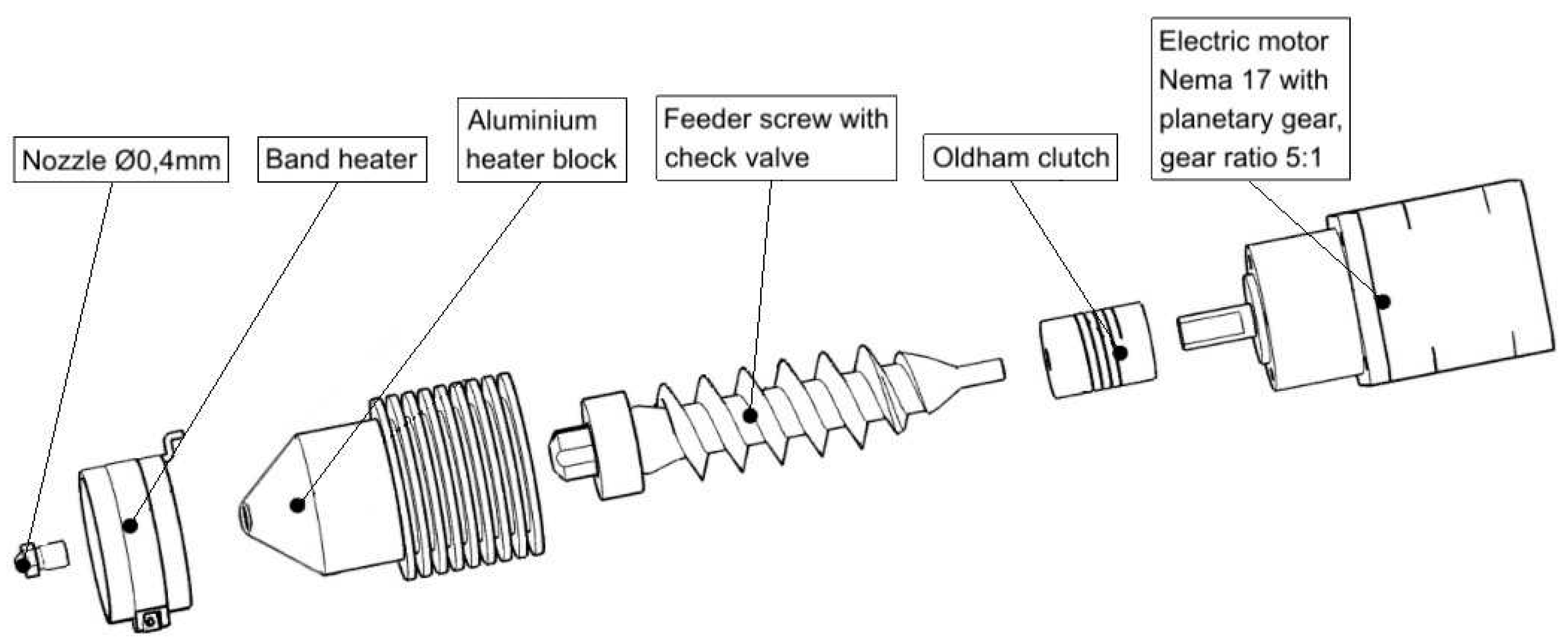
In
Figure 29, we can see that the extrusion system is integrated directly into the already designed printhead. However, unlike the common components of the “Hotend” and “Bowden” system, it has a reduced version, similar to the large-capacity device used to process the granulate into a filament. The design of the structure consists of an electric motor (3), which transmits the torque to the feeder screw (8) via a flexible coupling (4). It has a check valve (12) at its end. It is designed to close when the nozzle becomes clogged or too high in the injection chamber’s overpressure to prevent the melt from running back into the printhead. A hopper forms its other parts for granulate (5), passive cooling (9) placed so as to ensure the correct course of temperatures during the extrusion of granulate or melt. The heating system (10) is located at the end of the printhead and, unlike a commonly used heater, is in the form of a hoop. It is used due to the need to achieve higher temperatures in the processing of recycled plastics. The mechanism is terminated by an airbrush nozzle (11), the shape of which is more suitable for non-planar layering of material.
The presented conceptual design (
Figure 30) eliminates this device’s use by eliminating the use of this device and the granulate is processed directly in the print head.
By integrating this system into the device, we expect up to a 20% reduction in time for low-capacity production compared to the regular recycling plastic waste method.


 ,
, 


