Article

Investigation of the Structural Response of the MRE-Based MDOF Isolated Structure under Historic Near- and Far-Fault Earthquake Loadings

1
School of Civil and Environmental Engineering, National University of Sciences and Technology (NUST), Islamabad H-12, Pakistan
2
Military College of Engineering, National University of Sciences and Technology (NUST), Risalpur 24080, Pakistan
3
Institute of Applied Physics and Materials Engineering, University of Macau, Avenida da Universidade, Taipa 2623, China
*
Authors to whom correspondence should be addressed.
Appl. Sci. 2021, 11(6), 2876; https://doi.org/10.3390/app11062876
Submission received: 4 February 2021 / Revised: 23 February 2021 / Accepted: 28 February 2021 / Published: 23 March 2021

Abstract

:
Fixed base structures subjected to earthquake forces are prone to various issues, such as the attraction of greater forces to structure, amplified accelerations to non-structural components, expensive design for better seismic performance, and so forth. Base isolation applied at the foundation of vulnerable structures is a radical bypass from the conventional approaches utilized by structural engineers. However, the practical implementation of passive base isolation is constrained by factors such as large displacements at isolation level, uplifting forces at isolators, and vulnerability to unpredictable and versatile earthquakes. This study is focused on the evaluation of the smart base isolation system under various harmonic and earthquake loadings. The proposed system employs a magnetorheological elastomer (MRE)—a class of smart materials, based on an adaptive isolation layer under the building structure for its vibration control. The building is idealized as a five-degree-of-freedom (DOF) structure with the mass lumped at each storey. The stiffness of the MRE isolation layer is adjusted using the linear quadratic regulator (LQR) optimal feedback control algorithm. A total of 18 simulations have been performed for the fixed base, passively isolated, and MRE-based isolated structures under a series of earthquake loadings of both a near-fault and far-fault nature for analyzing a total of 306 responses of the structures. The simulation results indicate that MRE-based isolation has significantly reduced all the responses compared to the passively isolated structure for both the near-fault and far-fault earthquake loadings. For harmonic loading, however, the passively isolated structure outperformed the MRE isolated structure in terms of storey drift and acceleration responses.

1. Introduction

Base Isolation is a technique that has been successful in mitigating vibrations in the dynamic system [1,2]. For building structures, it is commonly introduced at the foundation level which isolates the superstructure from earthquake accelerations that can be destructive to the structure [3,4]. Through base isolation, the superstructure is decoupled from the vibrations and the frequency of the dynamic system is thus modified [5,6]. Base isolators working on conventional principles are prone to vulnerabilities to far-fault and near-fault earthquakes [7,8]. Earthquakes from far faults feature low-frequency range vibrations that can induce resonance and amplify the response of the structure [9,10]. Near-fault earthquakes have vibration characteristics of a high amplitude and long-period velocity pulse resulting in failure of the base isolator itself [11,12,13]. Further, the seismic isolators working on conventional principles have been ineffective for near-fault earthquakes, as they cause the structure to operate in its inelastic range for even design level earthquakes [1,2]. When a structure goes in the inelastic range, several fatigue-related issues [14,15] have to be considered, which makes the problem of vibration control even more challenging. Then, the passive nature of base isolators working on conventional principles limits the effective operation of the devices to only the predicted earthquakes and renders them ineffective for unprecedented earthquakes in the area [16,17]. Efforts have been made to overcome the problems associated with conventional vibration control techniques [18,19]. Active base isolation systems are designed by introducing active control strategies in tandem with passive base isolation [20]. These work by external energy supplied to the system that imparts forces to structure [21].
So far, numerous active control mechanisms and strategies have been adopted by researchers and structural engineers. Consequently, several active base control systems have been proposed and studied [22,23]. Reinhorn et al. [24] studied the shape control of structures undergoing inelastic deformations by employing an active pulse/force system. Kelly et al. [22] proposed the application of robust control in tandem with base isolation to minimize the total structural displacement and velocity. The control forces are designed in a way to overcome the forces generated by the isolation system at the base of the structure. Yoshida et al. [25] investigated the application of LQG and H∞ control strategies with hybrid base isolation systems by computer simulations. Additionally, several efforts have been made in parallel to verify the effectiveness of active base isolation systems in minimizing the structural response [23,26]. Despite a great number of efforts on analytical and experimental research, numerous full-scale structures have still been equipped with active control systems, and the implementation of base isolation with active control around the world has not been adopted yet. The primary reasons for this are the lack of real-time controllable isolation devices, high budget requirements for both implementation and maintenance, the requirement of high external power, system reliability and robustness, and lack of acceptance of non-conventional technology [21]. High power requirements of the actuators being a major challenge necessitated alternative approaches, which led to the developing of semi-active base isolation systems in which supplementary semi-active energy dissipation or displacement control devices are introduced [21]. These devices are adaptable and have low power requirements.
Magnetorheological fluid (MRF) dampers have also been explored for base isolation [3,27,28]. MRFs are smart materials whose rheological properties can be controlled by changing the applied external magnetic field [29]. MR materials comprise of micro-sized iron particles dispersed in non-magnetic elastic matrix. When a magnetic field is applied, the rheological properties of these materials can be rapidly and reversibly changed [30]. These have quick responsiveness to the magnetic field, rapid reversibility, and controllable performance which make these an excellent choice for use in applications in which controlled energy dissipation is needed, e.g., brakes and clutches for exercise equipment [31] and controllable dampers for vehicle suspensions [32]. A controllable fluid damper developed with MRFs is a popular device with semi-active control. These dampers have attracted considerable attention and interest from researchers. The greatest strength of MRF dampers is their assembly with a considerably simple and thus reliable design. It does not contain any moving parts other than the piston [21].
It can be noted that all the “smart” base isolation strategies achieve a certain level of “smartness” by making use of additional variable damping through active or semi-active dampers to conventional base isolation, often known as hybrid base isolation. This supplementary damping has been studied by Kelly [33] in more detail who concluded with adequate satisfaction that the use of supplementary dampers in base isolation is a misplaced effort and is a source of undesirable problems. The damping primarily controls vibration responses under the circumstances of steady-state resonance and a free vibration stage [34]. Nevertheless, while operating under the impact load, which is particularly featured in near-fault earthquakes, the availability of ample time becomes a bottleneck for damping to dissipate vibrational energy. Additionally, although the supplementary damping may forcefully confine the base displacement of the passive base isolation system [35], the high-frequency accelerations as well as an increase in inter-storey drifts may be introduced to the superstructure by augmenting damping [36]. Further, the MRF-based dampers have their inherent disadvantages such as long-term particle deposition and environmental contamination, etc. [37].
In order to achieve an ideal performance of base isolation while avoiding the issues associated with additional dampers, the seismic isolator itself should be adaptable. To achieve this, magnetorheological elastomers (MREs) have been studied by researchers for use in base isolators [38,39,40]. MREs are controllable composites that are mainly composed of magnetic fillers (commonly iron particles) and elastomers as the dispersion matrix [41]. The efficiency of MREs has been thoroughly studied by varying different material parameters, such as matrix material [42,43,44], size [39,45,46,47], percentage content [42,48,49,50], type and shape of filler material, and operation mode of the MRE material [39,45]. Unlike MRFs, MREs exhibit stable magnetorheological performance because the particles do not undergo sedimentation with time,. Moreover, the thermal stability of MREs is also superior as compared to MRFs. Other advantages of MREs are quick response time (less than milliseconds [51]) and having magnetic field-dependent yield stress.
Due to the magnetic field-dependent properties of MREs, they have various applications in different fields of engineering [41]. In civil engineering structures, MREs have been used primarily in the development of adaptive seismic isolators [39,52]. Studies have been conducted to investigate the suitability of MRE-based isolation systems [39,53] which validated that MR elastomer base isolation outperforms the traditional passive system in terms of response improvement during earthquake excitations. Jung et al. [40] developed a single-degree-of-freedom scaled-down structure model above an MR elastomer and performed experimental testing on the system under harmonic excitation and earthquake time histories. Behrooz et al. [54] developed a variable stiffness and damping isolator (VSDI) for base isolation of a civil structure. Four MRE samples, each 12 mm thick and trapezoidal were proposed in the design with a shim dividing them. Four electromagnetic coils were provided on the top and bottom of MRE samples to generate the magnetic flux. The coils were covered with two steel caps along with steel cores. The overall dimensions of VSDI are 128 mm × 64 mm × 110 mm. The number of turns in a single-coil is 800, and the power required for each device is 234.2W at a 4 A current. A maximum stiffness increase of 57% was reported in shear mode. However, the main drawback of this design of the isolator for civil structures is the limited loading capacity in the vertical direction. Li et al. [
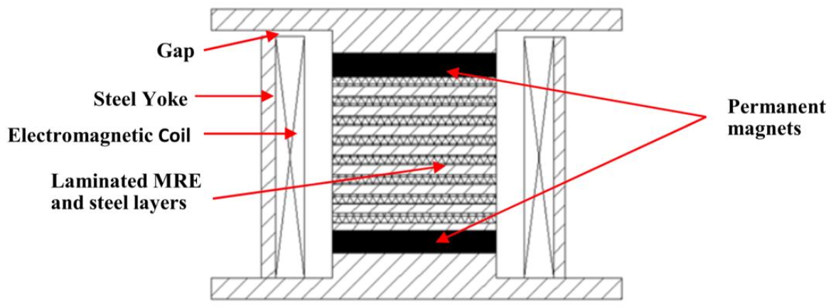
55,56] put forward, for the first time, a laminated MRE base isolator containing 47 sheets of MR elastomer each 2 mm thick with a diameter of 140 mm. Every MRE layer is accompanied by a 1-mm-thick steel sheet of the same diameter with a total of 46 steel sheets. This configuration makes the laminated structure 140 mm high. An electromagnetic coil was positioned outside the laminations. An enclosed magnetic path is formed with the steel plates at the top and bottom; the hollow steel yoke, the cylindrical steel block, and the laminated structure also form the core of the electromagnetic coil. The benefits of the laminated design are greater vertical loading capacity of the isolator and an improved magnetic conductivity of the structure and the widely practiced design of the MRE base isolator as shown in Figure 1. This device can take a maximum load of 370 kg in compression for its weakest state, i.e., 0 magnetic flux, and at a maximum design displacement of 26 mm. An even greater vertical loading capacity is expected under the application of a magnetic field. This loading capacity furnishes the minimum requirements for its use in the seismic isolation of civil structures. Experimental tests on a shake table demonstrated an effective stiffness increase of 37% and of 45% of force under a designed maximum current of 5A. The uniform magnetic field of 0.3 T is estimated to energize all of the MR elastomer layers in the device. Furthermore, an MR elastomer of a highly adjustable nature with a laminated structure was developed and experimentally tested by Li et al. [5] using a soft MRE. The device contains 25 sheets of MR elastomer, each 1 mm thick with diameters of 120 mm. The MR elastomer used in the new device can produce a force increase of 1479% and a stiffness increase of 1630% when the magnetic field varied from 0T to 0.44T. Yang et al. [57] conducted a study on the design and experimental testing of a novel MRE-based isolator with a hybrid magnetic system. A negative stiffness change in the isolator has been reported due to the incorporated hybrid magnetic system. The stiffness of the isolator can be increased or decreased based on the direction of current in the proposed isolator design.
The current trend on studies of MRE-based seismic isolation is focused on the development of isolation devices, their mathematical models, and subsequent necessary improvements/modifications in them for their effective implementation in large civil structures. No explicit research for MRE base isolation, however, has been conducted to gauge its effectiveness for near-fault and far-fault earthquakes. Since its performance for near-fault and far-fault earthquakes is a major drawback for passive base isolation systems, it is pretty much indispensable to obtain a comparison of the structural responses for both the systems, i.e., passive base isolation and MRE-based seismic isolation and to gauge how much response improvement is possible by employing MRE base isolation techniques for the case of both near-fault and far-fault earthquakes.
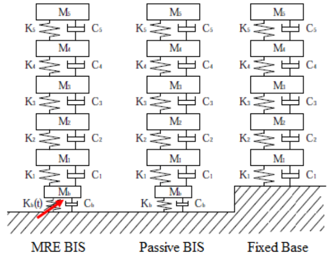
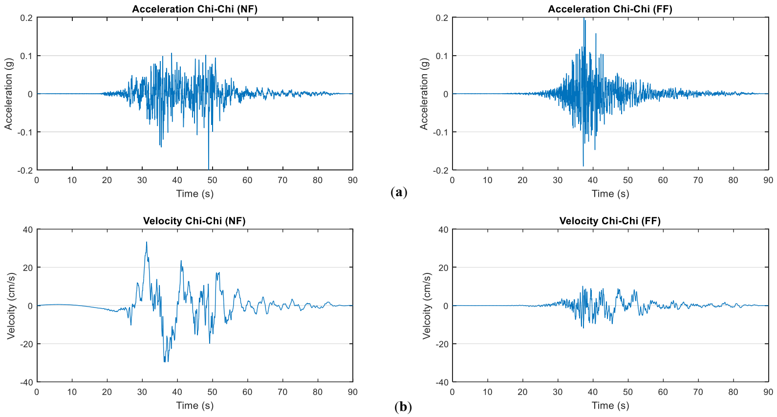
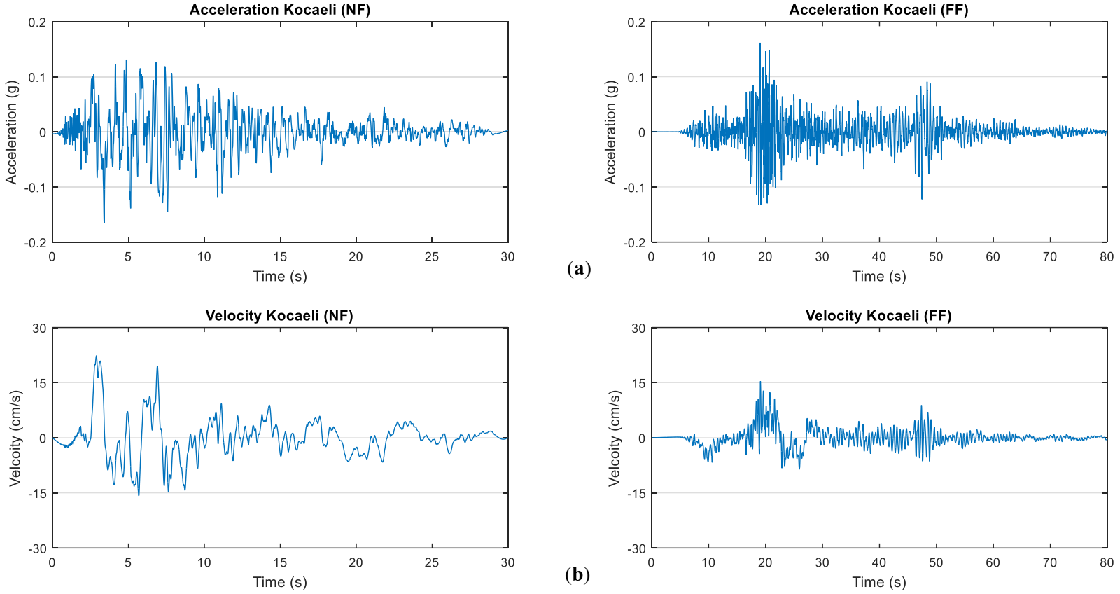
This study is focused on the investigation of the structural response of magnetorheological elastomers (MRE)-based multi-degree-of-freedom (MDOF) isolated structures under historic earthquake loadings. The effectiveness of MRE base isolation has been analyzed for near- and far-fault earthquakes individually first, and a comparison has been drawn afterward. The study involves identifying the historical near-fault and far-fault earthquakes, applying the selected earthquake loadings to the fixed base and passively isolated buildings, selecting and implementing suitable control strategy on passive isolator for varying its stiffness in real-time to simulate MRE-based smart isolation, and simulating the building models for selected earthquake loadings using closed-loop feedback control and obtain the responses. Consequently, a total of 612 responses from the three structures with 1x5 and 2x6 degrees-of-freedom (DOFs) have been analyzed for six earthquake time histories for each structure and a comparison has been made at the end.

2. Methodology

2.1. Structure Parameters and Characteristics

A benchmark building structure [39,58] has been used for evaluating the structural response. The building structure can be idealized as a 5-degree-of-freedom (DOF) model with mass lumped at each storey. The simple representation of the idealized model is shown in Figure 2.
With the addition of an isolation layer, the model can be treated as a 6-degree-of-freedom system for both passive and MRE-controlled isolated structural models. In Figure 2, M, K, and C represent mass, stiffness, and damping, while their subscripts represent the level at which the given values are applicable. For example, Mb is mass at the isolation layer. Similarly, Kb is stiffness and Cb is damping coefficient at isolation level. Since MRE-controlled isolation tends to change its stiffness at any time instance, the stiffness is denoted as K(t).
The adopted [39,58] parameters of the building model and isolation layer used for simulation are presented in Table 1 and Table 2, respectively.
Using the above parameters, the corresponding structure characteristics such as time period and natural frequencies can be worked out as they are the Eigenvalues depending on the mass and stiffness of the structure. These are tabulated in Table 3.

2.2. Equation of Motion and System Matrices

Assuming linear structure properties and representing the displacements relative to the ground as
x   =   x b   x 1   x 2   x 3   x 4   x 5
the equation of motion for structure reduced into matrix form can be expressed as:
M x ¨ t   +   C x ˙ t   +   K x t   =   γ u t   +   δ x ¨ g
The mass, stiffness, and damping matrices for the fixed base system are 5 × 5 matrices, and for the base-isolated structure they are 6x6 matrices and are widely expressed as generalized in Equations (3), (4), and (5), respectively.
M   = M a s s   M a t r i x = m b 0 0 m 5
C   = D a m p i n g   M a t r i x =   c b + c 1 c 1 c 1 c 1 + c 2 0 0 c 5
K   = S t i f f n e s s   M a t r i x =   k b + k 1 k 1 k 1 k 1 + k 2 0 0 k 5
γ is the force location matrix to be used only for MRE based isolated structure model. For fixed base and passive isolated models, γ would be a null matrix. Similarly, u(t) is the applied force and applicable only to the MRE isolated structure model.
γ   =   n   ×   r   force   location   matrix   =   1 0 0 0 0 0 T
u ( t )   =   u t b u t 1 u t 2 u t 3 u t 4 u t 5 T
δ is the coefficient vector for earthquake ground acceleration, x ¨ g . δ will be 5 × 1 for the fixed base structure model and 6 × 1 for isolated structure models.
δ   =   m 1 m 2 m 3 m 4 m 5   for   fixed   base   structure
δ   =   m b m 1 m 2 m 3 m 4 m 5   for   isolated   structure

2.3. State-Space Representations

Equation (2) can be re-arranged in terms of structural acceleration as
x ¨ t   = M 1 C x ˙ t     M 1 K x t   +   M 1 γ u t   +   M 1 δ x ¨ g t
Equation (10) can be re-written in the form
x ¨ t   = M 1 C x ˙ t     M 1 K x t   +   M 1 γ u t   +   M 1 δ x ¨ g t
x ˙ t x ¨ t   =   0 I M 1 K M 1 C x t x ˙ t   +   0 M 1 γ u t   +   0 M 1 δ x ¨ g t
The second-order equation of motion (2) can be cast to its first-order state-variable representation by defining the following state vector to apply linear control theory developed for first-order dynamic systems [59,60,61].
Z t   =   x t x ˙ t
Then, Equation (12) can be expressed as properties, representing the displacements relative to the ground as
{ Z ˙ t } =   A Z t   +   B u u t   +   B r x ¨ g t
where
Z ˙ t   =   x ˙ t x ¨ t
Then matrix [A] in Equation (14), also known as the plant matrix, would be a 10 × 10 matrix for the fixed base structure and a 12 × 12 matrix for isolated structure models, and will be expressed as:
A   = 0 I M 1 K M 1 C
[Bu] would be the null matrix for the fixed base and passive base-isolated structure model and a 12 × 1 matrix for the MRE isolated structure model, and will be expressed as:
B u   = 0 M 1 γ
[Br] would be a 10 × 1 vector for the fixed base structure and a 12 × 1 vector for both the passive base-isolated structure and MRE isolated structure models. It can be expressed as:
B r   = 0 M 1 δ

2.4. Linear Quadratic Regulator (LQR) Feedback Control

Equation (14) cannot be solved directly because the number of equations (12) is less than the number of unknown variables (13) in the case of base isolation, i.e., 12 × response outputs Z(t) and 1 × control force u(t). Thus, one more equation in this case is needed to solve the control problem. This required equation is referred to as the feedback control law. There are three control outlines through which the feedback control law can be implemented [59,60,61] to the smart structure model, i.e., open-loop feedback control, closed-loop feedback control, and open-closed loop feedback controls. For open-loop feedback control, the control force is determined by feedback of excitation at the base, such as sinusoidal motion or earthquake ground motion. The input information for its control law is only the base excitation data acquired with the help of accelerometers, etc. The obtained information is then used to calculate the required control force. For closed-loop feedback control, the control force is determined by the feedback of structure responses at each or some degrees-of-freedom. The input information for its control law consists of the structure responses such as velocities or relative displacements with the help of sensors. The acquired information is then used to calculate the required control force. The open–closed-loop scheme is a combination of both the closed-loop and open-loop control schemes. This can obtain information on both the ground motions and the structural responses. The control force is dependent on ground motion, displacement, and velocity responses [62].
Utilizing one of the above-discussed control schemes, Equation (14) can be solved mathematically. For a structure with closed-loop feedback control, the control force matrix is determined by using the measurements of response values and feeding them back to the equation. In this way, the feedback law will be given as
u t   = G Z t
In the case of the MRE base-isolated model, u will be a single value of force applied at the isolation level. G is a 1 × 12 matrix of feedback gain. Hence, the key parameter to make Equation (14) mathematically solvable is gain matrix G. In the current study, the gain matrix is obtained by using the linear quadratic regulator (LQR) algorithm and is discussed ahead.
Once G is obtained, the closed-loop system takes the form as expressed below
{ Z ˙ t } =   A c Z t   +   B r x ¨ g t
where Ac is the closed-loop plant matrix obtained through a substitution operation of Equation (19) into Equation (14), and expressed as
A c   =   A     B u G
The linear quadratic regulator (LQR) algorithm for structural control is an optimal control algorithm. The key objective of LQR is to minimize the following quadratic cost function J with respect to the control force input u(t).
J = 0 t z T t Q   z t   +   u T t   R   u t d t
In regulator-type algorithm problems, the system is idealized to be in equilibrium, and the LQR control algorithm serves the purpose of maintaining that equilibrium, even though the system is subjected to turbulences or of minimizing the response of the system under consideration from any sorts of disturbances [6].
The parameters Q and R in the quadratic cost function J are used as design parameters to penalize the state variables and the control signals, respectively. The larger these values, the greater the penalizing of these signals. Choosing a large value for R means the system is intended to become stabilized with less (weighted) force. This is usually known as an expensive control strategy. On the other hand, choosing a small value for R means the control force will not be penalized. Similarly, a large value for Q means the system is intended to become stabilized with the least possible changes in the states, and a small Q implies less concern about the changes in the states. So Q and R are the tuning knobs requiring adjustments to strike a balance between state response and control force.
There is an exclusive function of “lqr()” in MATLAB to calculate the gain matrix from the input of the closed-loop plant matrix Ac and Bu along with Q and R values. The syntax is shown below:
G , S , E   = l q r A c , B u , Q , R

2.5. Control Force

In this study, the MR elastomer is idealized as a linear stiffness element. Alhough the assumption of linear behavior does not represent the actual characteristics of MR elastomers, it does denote the general dynamics of the material in a small strain range and permits a rather simple approach to investigate the controllable isolation system [39].
The stiffness of the MR elastomer is expressed as K(t), which is the sum of actual (zero field) stiffness and the varying stiffness that is dependent on the external magnetic field or the current value through the electromagnetic coil. The MRE stiffness can be written as
K t   = K 0 + K 1 u t
where K0 is the actual (baseline) stiffness of MREs and K1(u(t)) denotes the variation in stiffness with time due to the command input u(t) at any time instant. In the current study, an MR elastomer material with an MR effect of 137% has been adopted [47]. Hence, the maximum value of the stiffness that can be physically achieved is K1,max = 1.37K0. Thus, K(t) will vary from 0 to 2.37K0. This maximum achievable stiffness value provides an upper limit to the control force that is
u t m a x K t m a x x b
For ensuring the optimal performance of the system, the control force u(t) has to be approaching the limit. If the control force is considerably lower than its upper limit, then the isolator would be underperforming, and if it is higher than the limit, then the isolator will not be able to generate the required force. Thus, some trials have to be performed for every excitation loading by varying Q and R parameters of the LQR algorithm until a control force equal to its limit is obtained.

2.6. Excitation Data

The fixed base, passively isolated, and MRE controlled isolated structures are subjected to earthquake excitations in form of acceleration for analyzing their responses. In the current study, near-fault earthquake ground motion [1,8,11,12,13,63,64,65,66,67,68,69,70,71] time histories have been selected from 1999 Chi-Chi, 1979 Imperial Valley, and 1999 Kocaeli earthquakes. These records are taken from Taichung, Brawley Airport, and Izmit stations, respectively [72]. Furthermore, another set of earthquake time histories, which are recorded from the same earthquake events under the same site conditions with the fault located at a distance far away from the site, is selected to demonstrate far-field ground motion characteristics [1,8,11,12,13,63,64,65,67,68,69,70,71,73]. The properties and description of the adopted time histories for near-fault and far-fault earthquakes are presented in Table 4 and Table 5, respectively.
The ground motion time histories are adapted from the PEER Strong Motion Database [72]. We aimed to acquire two sets of time history records (i.e., near-fault and far-fault) with the same peak ground acceleration of each earthquake (Chi-Chi 1999, Imperial Valley 1979, and Kocaeli 1999) for a more accurate and fair comparison of the results [69]. Thus, the selection of records has been made with more diligence. If the ground motion time histories of each earthquake were selected randomly (different peak acceleration values and/or site conditions), the meaningful comparison of the responses could not have been established with confidence. Thus, we aimed to eliminate this contradiction by selected ground motion records with the same peak acceleration values under the same site conditions [69,72].
The acceleration and velocity records of the adopted earthquake time histories are shown in Figure 3, Figure 4 and Figure 5. The same vertical scale in the plots has been adopted for near-fault and far-fault records for a particular earthquake loading to demonstrate the difference between the earthquakes. These figures show the significant velocity pulses for the near-fault ground motions compared to far-field records [70] despite having the same peak ground acceleration, which is one of the main characteristics of destructive near-field earthquake records [1,8,11,12,13,63,64,65,67,68,69,70,71,73].
In this way, a total of 12 simulations have been performed for each of the fixed base, passively isolated, and MR elastomer-based isolated structures using MATLAB. The cumulative number of simulations for all the three structures and 12 load cases totals 36. A total of 306 responses were compiled and analyzed, after which the results were processed, compared, presented, and discussed.

3. Results and Discussions

Six loading cases (time histories) for earthquake excitation [72] have been selected for evaluating the response of structures, out of which three are near-field and three are far-field [69,70]. The responses against the earthquake excitation are discussed below.

3.1. Displacement Responses

Displacement response is the total displacement of the storey at the corresponding degree-of-freedom. Representative displacement time history for Chi-Chi earthquake excitations is shown in Figure 6. It is clear from the figure that the passively isolated structure subjected to earthquake loading time history vibrates at a lower frequency and higher amplitude, whereas the fixed base structure vibrates at a much higher frequency. It can be observed from the time history plots that the MR elastomer-based isolated structure does not vibrate at any single value of frequency; rather, it responds by vibrating at a range of frequencies. Higher amplitudes of both the isolated structures are due to larger displacements at the isolation level.
Peak displacements relative to the base for all three structures and both near- and far-field stations of the Imperial Valley earthquake are presented in Figure 7. The green line indicates the fixed base structure, the blue the passively isolated structure (Passive BIS), and the red line the MRE base-isolated structure (MRE BIS). Thicker lines with box markers show the response against near-field (NF) earthquakes, whereas thinner lines with star markers show the response against far-field (FF) time history. It is evident from the figure that for both near-field and far-field time histories, MRE BIS has the lowest response, while the fixed base structure shows the highest displacement response. Furthermore, it can be observed that the response against the near-field earthquake time history is higher than that that of the far-field earthquake time history for all the three structures under consideration, despite having the same peak ground acceleration values in their records.
Storey-wise line plots for peak displacements are presented in Figure 8. It can be seen in the figures that for the isolated structures, a major portion of total displacement (96–99%) in the structure is absorbed at the isolation level due to the relatively soft isolation layer, and very minimal displacement is being transferred to the superstructure. Whereas for the fixed base model, all the displacement is transferred rather uniformly to the superstructure. Higher base drifts for the near-fault earthquake time histories compared to the far-fault earthquake time histories can be observed. A considerably lower response for the Kocaeli earthquake far-fault earthquake time histories can also be seen as compared to the other cases.
A comparison of peak displacement response for all the adopted earthquake time histories is presented in Figure 9. A greater response for the passively IS and greater subsequent reduction in response can be observed for the near-field earthquakes compared to the far-fault ones. It can also be observed that the response of the passively isolated structure against Kocaeli FF station is very low compared to that of other responses, thus its response reduction of MRE BIS compared to passively IS is also lower.
The average displacement response improvement of MRE BIS compared to the passively IS is presented in Figure 10. It is evident that response improvement is greater for the near-fault earthquake records compared to the far-fault ones.

3.2. Storey Drift Responses

Storey-drifts refer to the difference of displacement of two consecutive stories. Peak storey drift responses for both near- and far-field stations of the Chi-Chi earthquake are presented in Figure 11. The sme legends have been adopted as discussed previously with green, blue, and red representing fixed base, passively isolated, and MRE BIS, respectively, and a box marker against near-fault and a star marker against far-field earthquakes are used. Firstly, it is evident that storey drift responses decrease as we move from the bottom to the top storeys. It can also be observed that for both the near-field and far-field time histories, MRE BIS has the lowest response, while FBS shows the highest storey drift response. This validates the applicability of MRE BIS to earthquakes of both types, i.e., near-field and far-field. Similarly, it is evident that response against near-field earthquake time histories is higher than far-field earthquake time histories for all the three structures under consideration.
A comparison of peak storey drift response for all the adopted earthquake time histories is presented in Figure 12. Greater response for passively isolated structure and greater subsequent reduction in response can be observed for near-field earthquakes compared to far-field ones. It can also be observed that storey drift response of passively isolated structure against Kocaeli far-field station is very low compared to that of other responses, thus its response reduction of MRE BIS compared to a passively isolated structure is also lower.
The average storey drift response improvement of MRE BIS compared to passively IS is presented in Figure 13. It is evident that response improvement is greater for the near-fault stations compared to the far-field ones. However, no reduction in average response for Kocaeli far-field station earthquake case can be observed due to the discussed reasons [21,35,36] in the literature which states that this behavior is typical for hybrid base isolation systems where the supplementary force may forcefully confine the base displacement of the passive base isolation system at the expense of larger accelerations, as well as increased inter-storey drifts to the superstructure.

3.3. Acceleration Responses

Acceleration response refers to the total acceleration occurring at the corresponding degree-of-freedom/storey. Peak acceleration responses for near- and far-field stations of the Kocaeli earthquake are presented in Figure 14. The same legends have been adopted as discussed previously. For near-field stations, the fixed base structure has the highest response while MRE BIS shows the lowest. For the far-field stations, however, observation of passively isolated structures possessing minimum acceleration response can be made. This might be because the response of passively isolated structure against the far-field time histories is already very small and MRE BIS cannot improve it any further. This phenomenon can also be attributed to typical hybrid base isolation systems where the supplementary force forcefully confines the base displacement of the passive base isolation system for some cases [21,35] at the expense of larger accelerations as well as increased inter-storey drifts in the superstructure [21,36].
A comparison of peak acceleration response for all the adopted earthquake time histories is presented in Figure 15. A greater response for thepassively isolated structure and a greater subsequent reduction in acceleration response can be observed for the near-field earthquakes compared to the far-field ones. It can also be observed that the acceleration response of the passively isolated structure against the Kocaeli far-field station is very low compared to that of the other responses, thus its response reduction of MRE BIS compared to the passively isolated structure is also lower.
The average acceleration response improvement of MRE BIS compared to the passively isolated structure is presented in Figure 16. It is evident that response improvement is greater for the near-fault stations compared to the far-field ones. However, no reduction in average acceleration response for the Kocaeli far-field station time histories can also be observed. This behavior of increased inter-storey drifts and structural accelerations is typical for hybrid base isolation systems where the supplementary force may forcefully confine the base displacement of the passive base isolation system at the expense of larger accelerations as well as increased inter-storey drifts to the superstructure [21,35,36].

3.4. Summary of Results

The average response reduction of MRE BIS compared to passive IS for all the earthquake cases is summarized in Table 6:
This improvement is in agreement with the trends outlined in previous studies. A comparison is presented in Table 7.

4. Conclusions

A magnetorheological (MR) elastomer-based isolated structure has been modeled, and the response investigated for historical near-fault and far-fault earthquake time histories. The stiffness of the isolation layer was controlled utilizing the linear quadratic regulator (LQR) optimal control algorithm. The following conclusions can be drawn after analyzing the simulation results:
  • MRE BIS shows superior performance in the reduction of all three responses evaluated for all the near-field earthquakes compared to the passively isolated structure. Similarly, displacements, storey drifts, and structural accelerations have been reduced significantly compared to the fixed base structure.
  • MRE BIS shows superior performance in the reduction of displacement response for all the far-field earthquakes compared to passive BIS. Similarly, relative displacements, storey drifts, and structural accelerations have been reduced significantly compared to the fixed base system.
  • Apart from the Kocaeli (FF) excitation time history, MRE BIS shows significantly better performance in the reduction of storey drift and acceleration responses compared to passive BIS for all far-field earthquake excitations. The reasons have been discussed in detail in Section 3. This response may improve the application of a different control algorithm on the structure.
  • The response improvement of MRE BIS for all the three responses of displacement, storey drifts, and acceleration is greater for near-fault earthquakes compared to far-fault earthquake records for all the earthquake cases considered.

Author Contributions

M.A.T. (Formal analysis, Investigation, Writing-original draft); M.U. (Conceptualization, Methodology, Supervision, Writing-review & editing, Funding acquisition; S.H.F. (Validation, Supervision); I.U. (Formal analysis); A.H. (Visualization, Writing-review & editing, Project administration). All authors have read and agreed to the published version of the manuscript.

Funding

This research received no external funding.

Institutional Review Board Statement

Not applicable.

Informed Consent Statement

Not applicable.

Data Availability Statement

All required data is available within the manuscript.

Conflicts of Interest

The authors declare no conflict of interest.

References

  1. Bhandari, M.; Bharti, S.D.; Shrimali, M.K.; Datta, T.K. The Numerical Study of Base-Isolated Buildings under Near-Field and Far-Field Earthquakes. J. Earthq. Eng. 2018, 22, 989–1007. [Google Scholar] [CrossRef]
  2. Mazza, F.; Vulcano, A. Effects of near-fault ground motions on the nonlinear dynamic response of base-isolated r.c. framed buildings. Earthq. Eng. Struct. Dyn. 2012, 41, 211–232. [Google Scholar] [CrossRef]
  3. Yoshioka, H.; Ramallo, J.C.; Spencer, B.F. “Smart” Base Isolation Strategies Employing Magnetorheological Dampers. J. Eng. Mech. 2002, 128, 540–551. [Google Scholar] [CrossRef] [Green Version]
  4. Memon, S.A.; Zain, M.; Zhang, D.; Rehman, S.K.U.; Usman, M.; Lee, D. Emerging trends in the growth of structural systems for tall buildings. J. Struct. Integr. Maint. 2020, 5, 155–170. [Google Scholar] [CrossRef]
  5. Li, Y.; Li, J. A highly adjustable base isolator utilizing magnetorheological elastomer: Experimental testing and modeling. J. Vib. Acoust. Trans. ASME 2015, 137, 1–7. [Google Scholar] [CrossRef]
  6. Koo, J.H.; Jang, D.D.; Usman, M.; Jung, H.J. A feasibility study on smart base isolation systems using magneto-rheological elastomers. Struct. Eng. Mech. 2009, 32, 755–770. [Google Scholar] [CrossRef]
  7. Khan, B.L.; Azeem, M.; Usman, M.; Farooq, S.H.; Hanif, A.; Fawad, M. Effect of near and far field earthquakes on performance of various base isolation systems. Procedia Struct. Integr. 2019, 18, 108–118. [Google Scholar] [CrossRef]
  8. Chopra, A.; Chintanapakdee, C. Comparing Response of SDF Systems to Near-Fault and Far-Fault Earthquake Motions in the Context of Spectral Regions. Earthq. Eng. Struct. Dyn. 2001, 30, 1769–1789. [Google Scholar] [CrossRef]
  9. Tavakoli, H.R.; Naghavi, F.; Goltabar, A.R. Dynamic Responses of the Base-Fixed and Isolated Building Frames under Far- and Near-Fault Earthquakes. Arab. J. Sci. Eng. 2014, 39, 2573–2585. [Google Scholar] [CrossRef]
  10. Abdalla, J.A.; Petrovski, J.T.; Mohamedzein, Y.E. Vibration characteristics of a far field earthquake and its shaking effects on Dubai emerging skyscrapers. In Proceedings of the 14th World Conference on Earthquake Engineering, Beijing, China, 12–17 October 2008. [Google Scholar]
  11. Mavroeidis, G.P.; Papageorgiou, A.S. A mathematical representation of near-fault ground motions. Bull. Seismol. Soc. Am. 2003, 93, 1099–1131. [Google Scholar] [CrossRef]
  12. Koketsu, K.; Miyake, H. A seismological overview of long-period ground motion. J. Seismol. 2008, 12, 133–143. [Google Scholar] [CrossRef]
  13. Davoodi, M.; Sadjadi, M. Assessment of near-field and far-field strong ground motion effects on soilstructurec SDOF system. Int. J. Civ. Eng. 2015, 13, 153–166. [Google Scholar] [CrossRef]
  14. Hanif, A.; Usman, M.; Lu, Z.; Cheng, Y.; Li, Z. Flexural fatigue behavior of thin laminated cementitious composites incorporating cenosphere fillers. Mater. Des. 2018, 140, 267–277. [Google Scholar] [CrossRef]
  15. Khan, R.; Farooq, S.H.; Usman, M. Blast Loading Response of Reinforced Concrete Panels Externally Reinforced with Steel Strips. Infrastructures 2019, 4, 54. [Google Scholar] [CrossRef] [Green Version]
  16. Morgan, T.A.; Mahin, S.A. Performance-based design of seismic isolated buildings considering multiple performance objectives. Smart Struct. Syst. 2008, 4, 655–666. [Google Scholar] [CrossRef]
  17. Lee, C.W.; Kim, I.H.; Jung, H.J. Fabrication and Characterization of Natural Rubber-Based Magnetorheological Elastomers at Large Strain for Base Isolators. Shock Vib. 2018, 2018, 7434536. [Google Scholar] [CrossRef]
  18. Tanveer, M.; Usman, M.; Khan, I.U.; Ahmad, S.; Hanif, A.; Farooq, S.H. Application of tuned liquid column ball damper (TLCBD) for improved vibration control performance of multi-storey structure. PLoS ONE 2019, 14, e0224436. [Google Scholar] [CrossRef] [PubMed]
  19. Tanveer, M.; Usman, M.; Khan, I.U.; Farooq, S.H.; Hanif, A. Material optimization of tuned liquid column ball damper (TLCBD) for the vibration control of multi-storey structure using various liquid and ball densities. J. Build. Eng. 2020, 32, 101742. [Google Scholar] [CrossRef]
  20. Johnson, E.A.; Ramallo, J.C.; Spencer, B.F.; Sain, M.K. Intelligent Base Isolation Systems. In Proceedings of the Second World Conference on Structural Control, Kyoto, Japan, 28 June–1 July 1998. [Google Scholar]
  21. Gu, X. Investigation of Adaptive Base Isolation System Utilising Magnetorheological. Ph.D. Dissertation, University of Technology Sydney, Ultimo, Australia, 2017. [Google Scholar]
  22. Kelly, J.M.; Leitmann, G.; Soldatos, A.G. Robust control of base-isolated structures under earthquake excitation. J. Optim. Theory Appl. 1987, 53, 159–180. [Google Scholar] [CrossRef]
  23. Schmitendorf, W.E.; Jabbari, F.; Yang, J.N. Robust control techniques for buildings under earthquake excitation. Earthq. Eng. Struct. Dyn. 1994, 23, 539–552. [Google Scholar] [CrossRef]
  24. Reinhorn, A.; Soong, T.T.; Wen, C. Base isolated structures with active control. In Proceedings of the ASME PVD Conf, PVP-127; American Society of Mecanical Engineers (ASME): San Diego, CA, USA, 1987; pp. 413–420. [Google Scholar]
  25. Yoshida, K. LQG Control and H^∞ Control of Vibration Isolation for Multi-Degree-of-Freedom Systems. In Proceedings of the First World Conference on Structural Control, Los Angeles, CA, USA, 3–5 August 1994; Volume 2. [Google Scholar]
  26. Reinhorn, A.M.; Riley, M. Control of bridge vibrations with hybrid devices. In Proceedings of the First World Conference on Structural Control, Los Angeles, CA, USA, 3–5 August 1994; pp. 50–59. [Google Scholar]
  27. Yoshida, O.; Dyke, S.J. Seismic control of a nonlinear benchmark building using smart dampers. J. Eng. Mech. 2004, 130, 386–392. [Google Scholar] [CrossRef]
  28. Nagarajaiah, S.; Narasimhan, S. Smart base-isolated benchmark building. Part II: Phase I sample controllers for linear isolation systems. Struct. Control Health Monit. Off. J. Int. Assoc. Struct. Control Monit. Eur. Assoc. Control Struct. 2006, 13, 589–604. [Google Scholar] [CrossRef]
  29. Castañeda, P.P.; Galipeau, E. Homogenization-based constitutive models for magnetorheological elastomers at finite strain. J. Mech. Phys. Solids 2011, 59, 194–215. [Google Scholar] [CrossRef]
  30. Galipeau, E.; Castañeda, P.P. A finite-strain constitutive model for magnetorheological elastomers: Magnetic torques and fiber rotations. J. Mech. Phys. Solids 2013, 61, 1065–1090. [Google Scholar] [CrossRef]
  31. Jolly, M.R.; Bender, J.W.; Carlson, J.D. Properties and Applications of Commercial Magnetorheological Fluids. J. Intell. Mater. Syst. Struct. 1999, 10, 5–13. [Google Scholar] [CrossRef]
  32. Gu, X.; Yu, Y.; Li, J.; Li, Y. Semi-active control of magnetorheological elastomer base isolation system utilising learning-based inverse model. J. Sound Vib. 2017, 406, 346–362. [Google Scholar] [CrossRef] [Green Version]
  33. Naeim, F.; Kelly, J.M. Design of Seismic Isolated Structures: From Theory to Practice; John Wiley & Sons: Hoboken, NJ, USA, 1999. [Google Scholar]
  34. Crandall, S.H. The role of damping in vibration theory. J. Sound Vib. 1970, 11, 3-IN1. [Google Scholar] [CrossRef]
  35. Inaudi, J.A.; Kelly, J.M. Hybrid isolation systems for equipment protection. Earthq. Eng. Struct. Dyn. 1993, 22, 297–313. [Google Scholar] [CrossRef]
  36. Tsai, H.-C.; Kelly, J.M. Seismic response of heavily damped base isolation systems. Earthq. Eng. Struct. Dyn. 1993, 22, 633–645. [Google Scholar] [CrossRef]
  37. Sun, S.; Deng, H.; Yang, J.; Li, W.; Du, H.; Alici, G. Performance evaluation and comparison of magnetorheological elastomer absorbers working in shear and squeeze modes. J. Intell. Mater. Syst. Struct. 2015, 26, 1757–1763. [Google Scholar] [CrossRef]
  38. Usman, M.; Jung, H.J. Recent Developments of Magneto-Rheological Elastomers for Civil Engineering Applications. In Smart Material Actuators: Recent Advances in Material Characterization and Application; Nova Science Publishers: Hauppauge, NY, USA, 2015; ISBN 9781634825740. [Google Scholar]
  39. Usman, M.; Sung, S.H.; Jang, D.D.; Jung, H.J.; Koo, J.H. Numerical investigation of smart base isolation system employing MR elastomer. J. Phys. Conf. Ser. 2009, 149, 012099. [Google Scholar] [CrossRef]
  40. Jung, H.J.; Eem, S.H.; Jang, D.D.; Koo, J.H. Seismic performance analysis of a smart base-isolation system considering dynamics of MR elastomers. J. Intell. Mater. Syst. Struct. 2011, 22, 1439–1450. [Google Scholar] [CrossRef]
  41. Hafeez, M.A.; Usman, M.; Umer, M.A.; Hanif, A. Recent Progress in Isotropic Magnetorheological Elastomers and Their Properties: A Review. Polymers 2020, 12, 3032. [Google Scholar]
  42. Ge, L.; Gong, X.; Fan, Y.; Xuan, S. Preparation and mechanical properties of the magnetorheological elastomer based on natural rubber/rosin glycerin hybrid matrix. Smart Mater. Struct. 2013, 22, 115029. [Google Scholar] [CrossRef] [Green Version]
  43. Meunier, L.; Chagnon, G.; Favier, D.; Orgéas, L.; Vacher, P. Mechanical experimental characterisation and numerical modelling of an unfilled silicone rubber. Polym. Test. 2008, 27, 765–777. [Google Scholar] [CrossRef] [Green Version]
  44. Palacios-Pineda, L.M.; Perales-Martínez, I.A.; Moreno-Guerra, M.R.; Elías-Zúñiga, A. An optimum specimen geometry for equibiaxial experimental tests of reinforced magnetorheological elastomers with iron micro-and nanoparticles. Nanomaterials 2017, 7, 254. [Google Scholar] [CrossRef] [Green Version]
  45. Usman, M.; Jang, D.-D.; Kim, I.; Jung, H.-J.; Koo, J. Dynamic testing and modeling of magneto-rheological elastomers. In Smart Materials, Adaptive Structures and Intelligent Systems; AMSE: Oxnard, CA, USA, 2009; pp. 495–500. [Google Scholar]
  46. Li, W.H.; Zhou, Y.; Tian, T.F. Viscoelastic properties of MR elastomers under harmonic loading. Rheol. Acta 2010, 49, 733–740. [Google Scholar] [CrossRef]
  47. Khayam, S.U.; Usman, M.; Umer, M.A.; Rafique, A. Development and characterization of a novel hybrid magnetorheological elastomer incorporating micro and nano size iron fillers. Mater. Des. 2020, 192, 108748. [Google Scholar] [CrossRef]
  48. Lokander, M.; Stenberg, B. Performance of isotropic magnetorheological rubber materials. Polym. Test. 2003, 22, 245–251. [Google Scholar] [CrossRef] [Green Version]
  49. Von Lockette, P.R.; Kadlowec, J.; Koo, J.-H. Particle mixtures in magnetorheological elastomers (MREs). In Smart Structures and Materials 2006: Active Materials: Behavior and Mechanics; SPIE: Bellingham, WA, USA, 2006; Volume 6170, p. 61700T. [Google Scholar]
  50. Kelly, J.M. Aseismic base isolation: Review and bibliography. Soil Dyn. Earthq. Eng. 1986, 5, 202–216. [Google Scholar] [CrossRef]
  51. Böse, H.; Röder, R. Magnetorheological elastomers with high variability of their mechanical properties. J. Phys. Conf. Ser. 2009, 149, 12090. [Google Scholar] [CrossRef]
  52. Usman, M.; Ahmed, S.; Jung, H.-J. State-Switched Control Algorithm fo Multi Degree of Freedom Smart Base Isolation System Employing MR Elastomer. In Proceedings of the International Conference on Earthquake Engineering ans Seismology, Islamabad, Pakistan, 25–26 April.
  53. Hwang, I.-H.; Lim, J.-H.; Lee, J.-S. A study on base isolation performance of magneto-sensitive rubbers. J. Earthq. Eng. Soc. Korea 2006, 10, 77–84. [Google Scholar]
  54. Behrooz, M.; Wang, X.; Gordaninejad, F. Performance of a new magnetorheological elastomer isolation system. Smart Mater. Struct. 2014, 23, 045014. [Google Scholar] [CrossRef] [Green Version]
  55. Li, Y.; Li, J.; Li, W.; Samali, B. Development and characterization of a magnetorheological elastomer based adaptive seismic isolator. Smart Mater. Struct. 2013, 22, 035005. [Google Scholar] [CrossRef]
  56. Li, J.; Li, Y.; Li, W.; Samali, B. Development of adaptive seismic isolators for ultimate seismic protection of civil structures. Sensors Smart Struct. Technol. Civil Mech. Aerosp. Syst. 2013, 8692, 86920H. [Google Scholar] [CrossRef] [Green Version]
  57. Yang, J.; Sun, S.S.; Du, H.; Li, W.H.; Alici, G.; Deng, H.X. A novel magnetorheological elastomer isolator with negative changing stiffness for vibration reduction. Smart Mater. Struct. 2014, 23, 105023. [Google Scholar] [CrossRef]
  58. Ramallo, J.C.; Johnson, E.A.; Spencer, B.F., Jr. “Smart” base isolation systems. J. Eng. Mech. 2002, 128, 1088–1099. [Google Scholar] [CrossRef] [Green Version]
  59. Cheng, F.Y. Response control based on structural optimization and its combination with active protection. In Proceedings of the 9th World Conference in Earthquake Engineering, Kyoto, Japan, 2–9 August 1988; IAEE: Tokyo, Japan, 1988; Volume 3, p. 471. [Google Scholar]
  60. Cheng, F.Y. Application and Assessment of Structural Optimization and Active Control for Seismic Structures; NASA: Washington, DC, USA, 1990. [Google Scholar]
  61. Cheng, F.; Pantelides, C. Algorithm development for using optimal control in structural optimization subjected to seismic and wind forces. In NSF Report, US Department of Commerce, National Technical Information Service, NTIS No. PB90-1333471; US Department of Commerce: Washington, DC, USA, 1998. [Google Scholar]
  62. Cheng, F.Y.; Jiang, H.; Lou, K. Smart Structures: Innovative Systems for Seismic Response Control; CRC Press: Boca Raton, FL, USA, 2008. [Google Scholar]
  63. Davoodi, M.; Sagjadi, M.; Goljahani, P.; Kamalian, M. Effects of Near-Field and Far-Field Earthquakes on Seismic Response of SDOF System Considering Soil Structure Interaction. In Proceedings of the 15th World Conference on Earthquake Engineering, Lisbon, Portugal, 24–28 September 2012. [Google Scholar]
  64. Stewart, J.P.; Chiou, S.J.; Bray, J.D.; Graves, R.W.; Somerville, P.G.; Abrahamson, N.A. Ground motion evaluation procedures for performance-based design. Soil Dyn. Earthq. Eng. 2002, 22, 765–772. [Google Scholar] [CrossRef]
  65. Mavroeidis, G.P.; Papageorgiou, A.S. Near-source strong ground motion: Characteristics and design issues. In Proceedings of the US National Conference on Earthquake Engineering, Boston, MA, USA, 21–25 July 2002. [Google Scholar]
  66. Bommer, J. Strong motion parameters: Definition, usefulness and predictability. In Proceedings of the 12th World Conference on Earthquake Engineering, Auckland, New Zealand, 4 February 2014. [Google Scholar]
  67. Maniatakis, C.A.; Taflampas, I.M.; Spyrakos, C.C. Identification of Near-Fault Earthquake Record Characteristics. In Proceedings of the 14th World Conference on Earthquake Engineering, Beijing, China, 12–17 October 2008. [Google Scholar]
  68. Hall, J.F.; Heaton, T.H.; Halling, M.W.; Wald, D.J. Near-Source Ground Motion and its Effects on Flexible Buildings. Earthq. Spectra 1995, 11, 569–605. [Google Scholar] [CrossRef]
  69. Adanur, S.; Altunişik, A.C.; Bayraktar, A.; Akköse, M. Comparison of near-fault and far-fault ground motion effects on geometrically nonlinear earthquake behavior of suspension bridges. Nat. Hazards 2012, 64, 593–614. [Google Scholar] [CrossRef]
  70. Akkar, S.; Yazgan, U.; Gülkan, P. Drift estimates in frame buildings subjected to near-fault ground motions. J. Struct. Eng. 2005, 131, 1014–1024. [Google Scholar] [CrossRef]
  71. Moustafa, A.; Takewaki, I. Deterministic and probabilistic representation of near-field pulse-like ground motion. Soil Dyn. Earthq. Eng. 2010, 30, 412–422. [Google Scholar] [CrossRef]
  72. The Pacific Earthquake Engineering Research Center (PEER) Ground Motion Databases. Available online: https://peer.berkeley.edu/peer-strong-ground-motion-databases (accessed on 20 January 2021).
  73. Bommer, J.J.; Martinez-Pereira, A. Strong-motion parameters: Definition, usefulness and predictability. In Proceedings of the 12th World Conference on Earthquake Engineering, Auckland, New Zealand, 30 January–4 February 2000. [Google Scholar]
Figure 1. Magnetorheological elastomer (MRE) base isolator [57].
Applsci 11 02876 g001
Figure 2. Building structure idealized representation.
Applsci 11 02876 g002
Figure 3. Near-fault and far-fault ground motions recorded at the Chi-Chi earthquake in 1999. (a) Acceleration time histories for near-fault and far-fault earthquake records. (b) Velocity time-histories for near-fault and far-fault earthquake records [72].
Applsci 11 02876 g003
Figure 4. Near-fault and far-fault ground motions recorded at the Imperial Valley earthquake in 1979. (a) Acceleration time histories for near-fault and far-fault earthquake records. (b) Velocity time-histories for near-fault and far-fault earthquake records [72].
Applsci 11 02876 g004
Figure 5. Near-fault and far-fault ground motions were recorded at the Kocaeli earthquake in 1999. (a) Acceleration time histories for near-fault and far-fault earthquake records. (b) Velocity time-histories for near-fault and far-fault earthquake records [72].
Applsci 11 02876 g005
Figure 6. Displacement time history at storey 5 for the Chi-Chi earthquake.
Applsci 11 02876 g006
Figure 7. Peak displacements relative to base, Imperial Valley earthquake.
Applsci 11 02876 g007
Figure 8. Storey-wise total displacements.
Applsci 11 02876 g008
Figure 9. Peak displacement response at top storey against earthquake cases.
Applsci 11 02876 g009
Figure 10. Average displacement response reduction of MRE base-isolated structure (MRE BIS) compared to the passively IS.
Applsci 11 02876 g010
Figure 11. Peak storey drifts, Chi-Chi earthquake.
Applsci 11 02876 g011
Figure 12. Peak storey drifts response at storey 1.
Applsci 11 02876 g012
Figure 13. Average storey drifts response reduction of MRE BIS compared to passively IS.
Applsci 11 02876 g013
Figure 14. Peak acceleration, Kocaeli earthquake.
Applsci 11 02876 g014
Figure 15. Peak acceleration response at the top storey.
Applsci 11 02876 g015
Figure 16. Average acceleration response reduction.
Applsci 11 02876 g016
Table 1. Structure parameters.
StoreyMass (kg)Stiffness (kN/m)Damping (kN.s/m)
1589733,73267
2589729,09358
3589728,62157
4589724,95450
5589719,05938
Table 2. Base isolation parameters.
Stiffness232 kN/m
Damping3.74 kN.s/m
MR Effect137%
Table 3. Structure vibration characteristics.
Fixed BasePassive BIS
ModeFrequency (Hz)Time Period (s)Frequency (Hz)Time Period (s)
13.200.310.402.5
28.720.115.470.2
313.620.0710.300.1
417.610.0614.730.07
520.920.0518.410.05
6--21.320.04
Table 4. Near-fault earthquake time histories.
EventMwStationPGAPGV (cm/s)Distance to a Fault (km)
Chi-Chi (1999)7.6Taichung0.2g36.39.5
Imperial Valley (1979)6.9Brawley Airport0.16g36.68.5
Kocaeli (1999)7.8Izmit0.17g22.64.8
Table 5. Far-fault earthquake time histories.
EventMwStationPGAPGV (cm/s)Distance to a Fault (km)
Chi-Chi (1999)7.6Ilan0.2g11.849
Imperial Valley (1979)6.9Compuertas0.15g9.535
Kocaeli (1999)7.8Fatih0.16g1264.5
Table 6. Percentage response reductions.
Excitation Time HistoryDisplacement Reduction (%)Storey Drift Reduction (%)Acceleration Reduction (%)
Chi-Chi (NF)78.2259.5459.26
Imperial Valley (NF)67.8250.3951.28
Kocaeli (NF)54.939.988.98
Chi-Chi (FF)69.7737.5124.93
Imperial Valley (FF)75.2046.6149.82
Kocaeli (FF)46.79−51.71−76.26
Table 7. Comparison with previous studies.
Parameter ReportedUsman et al. (2009) [39]Jung et al. (2011) [40]Ramallo et al. (2014) [58]This Study
MR Effect70%Not Reported30%137%
Structure Type5 DOF B.M.1 DOF Scaled2 DOF Scaled5 DOF B.M.
Investigation TypeNumericalExperimentalExperimentalNumerical
Control AlgorithmLQRFuzzy LogicLyapunovLQR
Displacement ReductionUp to 45%Up to 41%Up to 35%Up to 78%
Acceleration ReductionUp to 39%Up to 39%Up to 47%Up to 60%
Publisher’s Note: MDPI stays neutral with regard to jurisdictional claims in published maps and institutional affiliations.

