Article

A Symmetric Three-Layer Plate with Two Coaxial Cracks under Pure Bending

by
Mykhaylo Delyavskyy
1,*,
Viktor Opanasovych
2,
Roman Seliverstov
3 and
Oksana Bilash
4
1
Department of Mechanics Construction and Buildings Materials, Faculty of Civil, Architecture and Environmental Engineering, UTP University of Science and Technology, Al. Prof. S. Kaliskiego 7, 85-796 Bydgoszcz, Poland
2
Department of Mechanics, Faculty of Mechanics and Mathematics, Ivan Franko National University of L’viv, Universytetska St. 1, 79000 Lviv, Ukraine
3
Department of Programming, Faculty of Applied Mathematics and Informatics, Ivan Franko National University of L’viv, Universytetska St. 1, 79000 Lviv, Ukraine
4
Department of Engineering Mechanics (Weapons and Equipment of Military Engineering Forces), Faculty Training Specialists Battle (Operational) Software, Hetman Petro Sahaidachnyi National Army Academy, Heroes of Maidan Street, 32, 79026 Lviv, Ukraine
*
Author to whom correspondence should be addressed.
Appl. Sci. 2021, 11(6), 2859; https://doi.org/10.3390/app11062859
Submission received: 21 February 2021 / Revised: 10 March 2021 / Accepted: 15 March 2021 / Published: 23 March 2021
(This article belongs to the Section Mechanical Engineering)

Abstract

:

Featured Application

Authors are encouraged to provide a concise description of the specific application or a potential application of the work. This section is not mandatory.

Abstract

The purpose of this research was to investigate the effect of mechanical features and geometrical parameters on the stress–strain state of a cracked layered plate under pure bending (bending moments are uniformly distributed at infinity). The sixth-order bending problem of an infinite, symmetric, three-layer plate with two coaxial through cracks is considered under the assumption of no crack closure. By using complex potentials and methods of the theory of functions of a complex variable, the solution to the problem was obtained in the form of a singular integral equation. It is reduced to the system of linear algebraic equations and solved in a numerical manner by the mechanical quadrature method. The distributions of stresses and bending moments near the crack tips are shown. Numerical results are presented as graphical dependences of the reduced moment intensity factor on various problem parameters. In this particular case, the optimum ratio of layer thicknesses is determined.

1. Introduction

Plate-shaped structures are widely used in engineering and are often operated under bending loads. Their destruction is largely caused by crack propagation, therefore, acquiring information about crack tip stresses under such conditions is very important.
Two-dimensional sixth-order plate theories are popular in the scientific community. They use simpler (compared to the three-dimensional theories) relations of the elasticity theory and at the same time, they allow one to take into account the plate thickness and material anisotropy. The results of the first investigations into the stress–strain state of cracked plates have been collected in the handbook [1]. The stress and displacement distribution near the crack tips are described in [2]. These, and most later published cracked plate bending investigations refer to homogeneous plates [3,4]. The bending of a homogeneous plate with coaxial cracks in terms of sixth-order theories has been investigated, for example, in [5,6,7]. Anisotropic and composite plates have not remained unheeded either. However, such investigations are mostly devoted to tensile loads [8], smooth-shaped cracks [9], anisotropic non-layered plates [10] and sandwich-structured non-cracked plates [11,12]. For plates with straight through cracks under bending load, the finite element method is usually used, for example [13]. Recently, new approaches have been proposed, for example, an energy-based modal decomposition method [14].
Analytical research of cracked layered plates in the frame of sixth-order theories was initiated by [15,16]. Models from these studies were adapted to the method of singular integral equations by [17].
Due to the lack of publicly available numerical and experimental research of the bending of layered plates with a system of through cracks, especially on the basis of refined theories, we decided to fill this gap, starting with a study of the effect of the presence of two coaxial cracks on the stress–strain state of the symmetric three-layer composite plate.
Mark meanings are listed in Table 1 to improve the understanding of the article by readers.

2. Materials and Methods

Consider an infinite, thin, three-layer plate of thickness h . The plate has physical and geometrical symmetry about its middle plane. The origin O of a chosen global Cartesian coordinate system O x y z ˜ is placed at the center of symmetry, the x y -plane coincides with the middle plane of the plate and the z ˜ axis is directed along the downward vertical plane. The transverse isotropy of each layer is assumed (the planes of isotropy are parallel to the middle plane). The material of the outer layers is characterized by Young’s modulus E 1 , Poisson’s ratio ν 1 in the plane of isotropy and the shear modulus G 1 in the transverse direction, the material of the inner layer—by E 2 , ν 2 and G 2 , respectively. We also require the conditions of an ideal mechanical contact at the interfaces z ˜ = ± h 1 / 2 .
The plate contains two equal through coaxial cracks of length 2 l . The centers O j (hereinafter j = 1 , 2 ) of the cracks have the coordinates x j = 1 j c + l , y j = z ˜ j = 0 and are the origins of local Cartesian coordinate systems O j x j y j z ˜ j (see Figure 1).
Let us determine and compute the moment intensity factor under pure bending (bending moments M y = M are applied at infinity and there is no contact between the faces of cracks). The absence of contact can be ensured by tensile loads at infinity, the contribution of which to the stress state of the plate can be obtained from the known solution of the plane problem of the elasticity theory [18]. The solution to the given problem is a superposition of the solutions to the following two problems: bending of the solid plate and of the plate with cracks under the corresponding load applied to their faces. We restrict ourselves to the second one, the boundary conditions of which in local coordinate systems are as follows:
M y + M y = H x y + H x y = Q y + Q y = 0 ,   x j < l ,
M y + M y = 2 M ,   H x y + + H x y = Q y + + Q y = 0 ,   x j < l ,
where M y , H x y , and Q y are bending moments, twisting moments and shear forces, respectively; superscripts “+” and “−” stand for limits at y ± 0 .
According to [15], the through-the-thickness displacement variation in the k -th layer can be expressed in the following form:
u k i v k = 2 z z ˜ W + f ˜ k z ˜ F i Ω , w ( k ) = W ,   k = 1 , 2 , 3 ,
where u ( k ) , v ( k ) and w ( k ) are components of displacement vector; z = x + i y , z = 1 2 x i y ; W x , y , F x , y and Ω x , y are unknown functions; f ˜ k z ˜ are odd functions which satisfy the condition f ˜ 3 z ˜ = f ˜ 1 z ˜ and matching conditions for the displacements and shear stresses at the interfacial zones between layers
f ˜ 1 h 1 2 = f ˜ 2 h 1 2 ,   G 1 d f ˜ 1 d z ˜ h 1 2 = G 2 d f ˜ 2 d z ˜ h 1 2 ,
and the additional condition
d f ˜ 1 d z ˜ h 2 = 0 .
The stress distribution in the k th layer is obtained by inserting (3) to the Hooke law:
σ x k + σ y k = 4 E k 1 ν k 2 z z ¯ z ˜ W + f ˜ k z ˜ F ,
σ y k σ x k + 2 i τ x y k = 4 E k 1 + ν k 2 z 2 z ˜ W + f ˜ k z ˜ F i Ω ,
τ z ˜ x k i τ z ˜ y k = 2 G k f ˜ k z ˜ z F i Ω ,
where
z ¯ = ¯ z ,   E 3 = E 1 ,   ν 3 = ν 1 ,   G 3 = G 1 .
Instead of stress tensor components (6) we will use integral parameters of stress state (bending moments M x and M y , twisting moment H x y and shear forces Q x and Q y ) which are the following
M x + M y = k = 1 3 z ˜ k 1 z ˜ k z ˜ σ x k + σ y k d z ˜ = 4 2 z z ¯ m W m ˜ F ,
M y M x + 2 i H x y = k = 1 3 z ˜ k 1 z ˜ k z ˜ σ y k σ x k + 2 i τ x y k d z ˜ = 4 2 z 2 n W + n ˜ F i Ω [ F i Ω ] ,
Q x i Q y = k = 1 3 z ˜ k 1 z ˜ k τ z ˜ x k i τ z ˜ y k d z ˜ = 2 ρ ˜ z F i Ω ,
where
z ˜ 3 = z ˜ 0 = h 2 ,   z ˜ 2 = z ˜ 1 = h 1 2 ,   m = h 3 12 E γ 3 1 1 ν E 1 γ 3 1 ν 1 ,
m ˜ = k = 1 3 z ˜ k 1 z ˜ k E k 1 ν k z ˜ f ˜ k z ˜ d z ˜ ,   n = h 3 12 E 1 γ 3 1 + ν + E 1 γ 3 1 + ν 1 ,
n ˜ = k = 1 3 z ˜ k 1 z ˜ k E k 1 + ν k z ˜ f ˜ k z ˜ d z ˜ ,   ρ ˜ = k = 1 3 G k f ˜ k z ˜ k f ˜ k z ˜ k 1 .
Suppose that f ˜ k z ˜ is given by the following cubic polynomials:
f ˜ 1 z ˜ = A z ˜ + B z ˜ 3 h 1 2 z ˜ h 2 ,   f ˜ 2 z ˜ = z ˜ + C z ˜ 3 z ˜ h 1 2 .
The values of A , B and C are obtained from (4) and (5):
A B C = 2 1 β γ 2 + 3 β 1 β 4 β / 3 h 2 2 β 3 γ 2 + 3 1 β / 3 h 1 2 ,   γ = h 1 h ,   β = G 2 G 1 ,
It is shown in [13] that following equations take place
Δ Δ W = 0 ,   F = ρ 2 ρ ˜ Δ W ,   Ω 2 ρ ˜ n ˜ Ω = 0 ,
where Δ is a Laplace operator, ρ = n m .
Represent W in terms of analytical functions   φ z and χ z by the Goursat′s formula W = Re z ¯ φ z + χ z . Therefore, from (10) we obtain F = 2 ρ ρ ˜ Re Φ z , where z = φ z . Taking into account (8) and (9), the integral parameters (7) can be written as follows
M y + i H x y = 2 m Re Φ z + n z ¯ Φ z + Ψ z + 2 ρ k 2 2 2 Φ z z 2 i 2 Ω ˜ z ,   z ¯ z ¯ 2 ;
Q x i Q y = ρ 2 Φ z z i Ω ˜ z ,   z ¯ z ,
where
Ω ˜ z ,   z ¯ = 2 ρ ˜ ρ Ω ,   Δ Ω = k 2 Ω ,
k 2 = 40 h 2 2 + γ β 1 3 γ 2 E G 1 + ν γ 5 5 γ 3 + 4 + E 1 γ 3 G 1 1 + ν 1 1 2 β γ 2 + 6 β 1 ,
Ψ z = χ z .
Using the approach from [5], represent   Φ z and Ω ˜ z , z ¯ in the form
Φ z = 1 2 π i L f t d t t z ,   Ω ˜ z , z ¯ = 1 π i L w K 1 w 1 t z 1 t z ¯ f t d t ,
where   L = x | c < x < c + 2 l , w = k t x 2 + y 2 , hereinafter   K i x is the Macdonald function of   i th order,   f t is an unknown real-valued function.
By introducing the new functions
V z = m n Φ ¯ z + z Φ ¯ z + Ψ ¯ z ,   Φ ¯ z = Φ z ¯ ¯ , Ψ ¯ z = Ψ z ¯ ¯ ,
Ω 1 z ,   z ¯ = Ω ˜ z 1 π i L f t d t t z 2 ,   Ω 2 z ,   z ¯ = 2 Ω ˜ z 2 2 π i L f t d t t z 3 ,
and using (13) we rewrite (11) and (12) as follows:
M y + i H x y = n m n Φ z + V z ¯ + z z ¯   Φ   z ¯ + i 2 ρ n k 2 Ω 2 z , z ¯ ¯ ,
Q x i Q y = i ρ Ω 1 z ,   z ¯ ,
where
Ω 1 z ,   z ¯ = i π L w 2 K ˜ 1 w t z 2 + t z ¯ k 4 t x w 2 f t d t ,
Ω 2 z ,   z ¯ = 1 π i L w 2 K ˜ 2 w t z 3 i k 2 2 Im   w K 1 w t z + 1 i k 6 y t z ¯ t x K 1 w w 3 f t d t ,
K ˜ 1 x = K 1 x 1 x ,   K ˜ 2 x = K 2 x 2 x 2 .
Functions   Ω 1 and   Ω 2 have the following properties:
Ω 1 + x ,   x = Ω 1 x ,   x = 0 ,   Ω 2 + x ,   x ¯ = Ω 2 x ,   x ¯ = k 2 f ( x ) ,   x L .
Taking into account (14)–(16) from the boundary conditions (1), we obtain a linear conjunction problem
V + x V x = 3 m n 2 f x ,   x L .
Problem (17) has the solution
V z = 3 m n 2 1 2 π i L f t d t t z .
Satisfying conditions (1), we conclude that g 1 t = 0 , g 2 t = 3 m n 2 f t .
Taking into account (14), (15), (18) and the symmetry of the problem, and satisfying the boundary conditions (2), leads to the following singular integral equation in an unknown function   g x ˜ = f l x ˜ .
1 π 1 1 R t , x ˜ g t d t = 2 M n ,   1 < x ˜ = x 2 l < 1 ,
with kernel
R t , x ˜ = a + b K ˜ 2 w ˜ t , x ˜ t x ˜ + a + b K ˜ 2 w ˜ 1 t , x ˜ t + x ˜ + d + 2 ,
where
a = 2 1 2 m n ,   b = 4 1 m n ,   d = 2 c l ,   w ˜ t , x ˜ = k l t x ˜ ,
w ˜ 1 t , x ˜ = k l t + x ˜ + d + 2 .
Equation (19) must be solved under the additional condition
1 1 g t d t = 0 ,
which ensures that displacements are single-valued when bypassing the contours of cracks.
Bending moment intensity factors are defined as
K M j ± = ± m l lim x ˜ j ± 1 1 x ˜ j 2 g x ˜ j ,   K M 1 + = K M 2 ,
where signs “+” and “ ” correspond to crack tips   x j = l and x j = l , respectively.
Distributions of bending moments, twisting moment, shear forces and stresses in the   k th layer near the crack tip are [15]:
M x M y H x y = K M 2 r cos θ 2 1 2 sin θ sin 3 θ 2 cos θ 2 + 1 2 sin θ sin 3 θ 2 1 2 sin θ cos 3 θ 2 + O 1 , Q x = Q y = O 1 ,
σ x ( k ) + σ y ( k ) = E k K M m ( 1 + ν k ) 2 r 2 ( 1 + ν k ) 1 ν k z ˜ cos θ 2 + O 1 ,
σ y k σ x k = E k K M m 1 + ν k 2 r 2 1 + m n z ˜ h ρ n ˜ f k 2 z ˜ h cos θ 2 z ˜ h ρ 2 n ˜ f k 2 z ˜ h sin θ sin 3 θ 2 + O 1 ,
τ x y k = E k K M m 1 + ν k 2 r h ρ 2 n ˜ f k 2 z ˜ h 1 + m n z ˜ sin θ 2 1 2 z ˜ h ρ 2 n ˜ f k 2 z ˜ h sin θ cos 3 θ 2 + O 1 , τ z ˜ x k = τ z ˜ y k = O 1 ,
where r ,   θ are polar coordinates that originate at the crack tip.

3. Results and Discussions

The system of integral Equations (19) and (20) is solved in a numerical manner, with the help of the mechanical quadrature method [18] of E 1 G 1 = 4 , E 2 G 2 = 2.5 , ν 1 = ν 2 = 0.3 and for various values of β , h l ,   d and γ . The nodal values of the sought-for function at zeros of the first kind Chebyshev polynomials, as solutions to system of linear equations, are obtained using Python′s NumPy library (the solve method from the linalg module). The bending moment intensity factor (21) is calculated for one of the two cracks from the formula
K M ± = 2 m n M l g ˜ ± 1 , g ˜ t = n 1 t 2 g t 2 M ,
where   N —number of nodes in mechanical quadrature method,
g ˜ 1 = 1 N i = 1 N 1 i + 1 g ˜ t i cot 2 i 1 4 N π ,
g ˜ 1 = 1 N i = 1 N 1 i + N g ˜ t i tan 2 i 1 4 N π ,
t i = cos 2 i 1 2 N π .
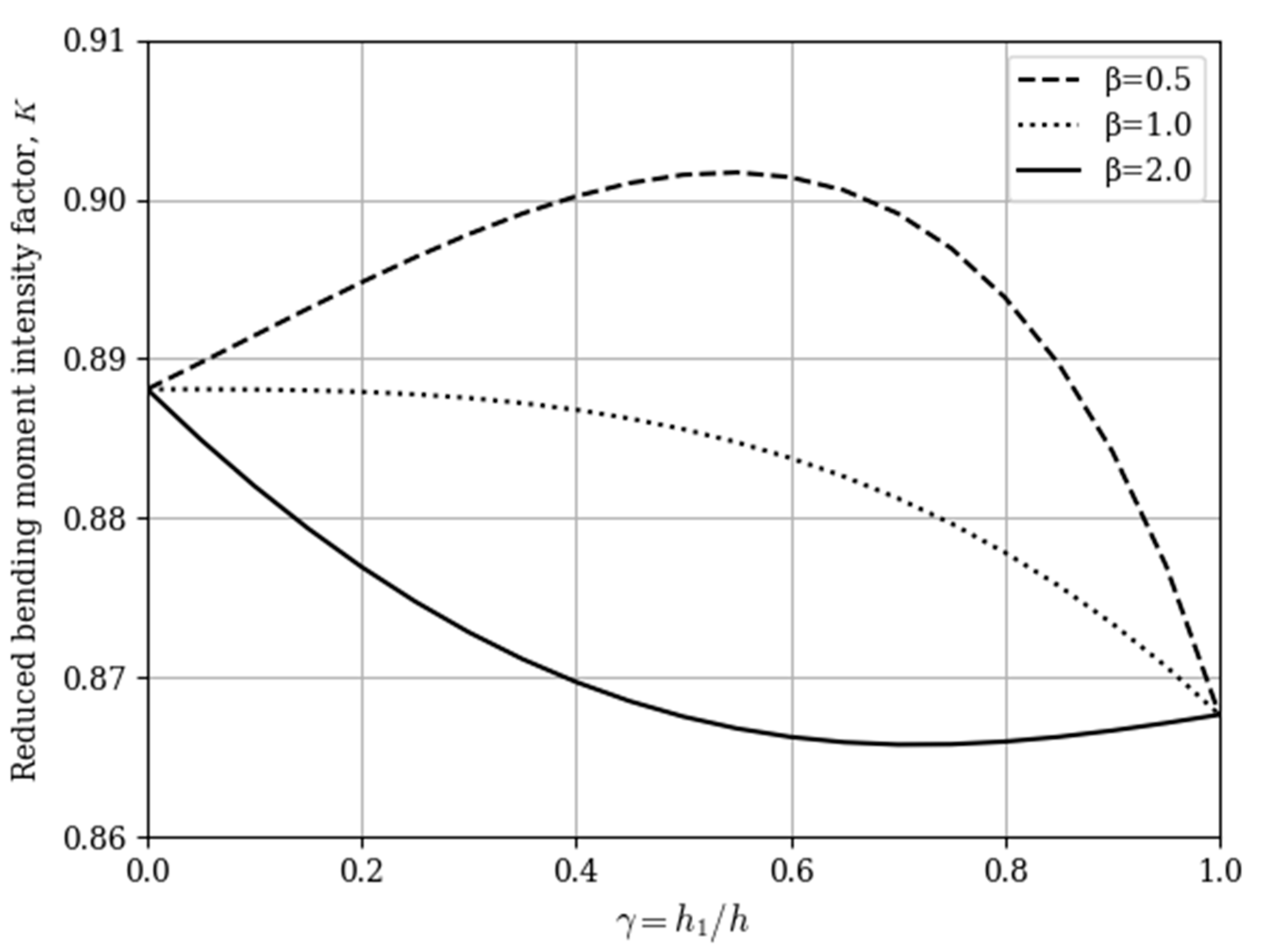
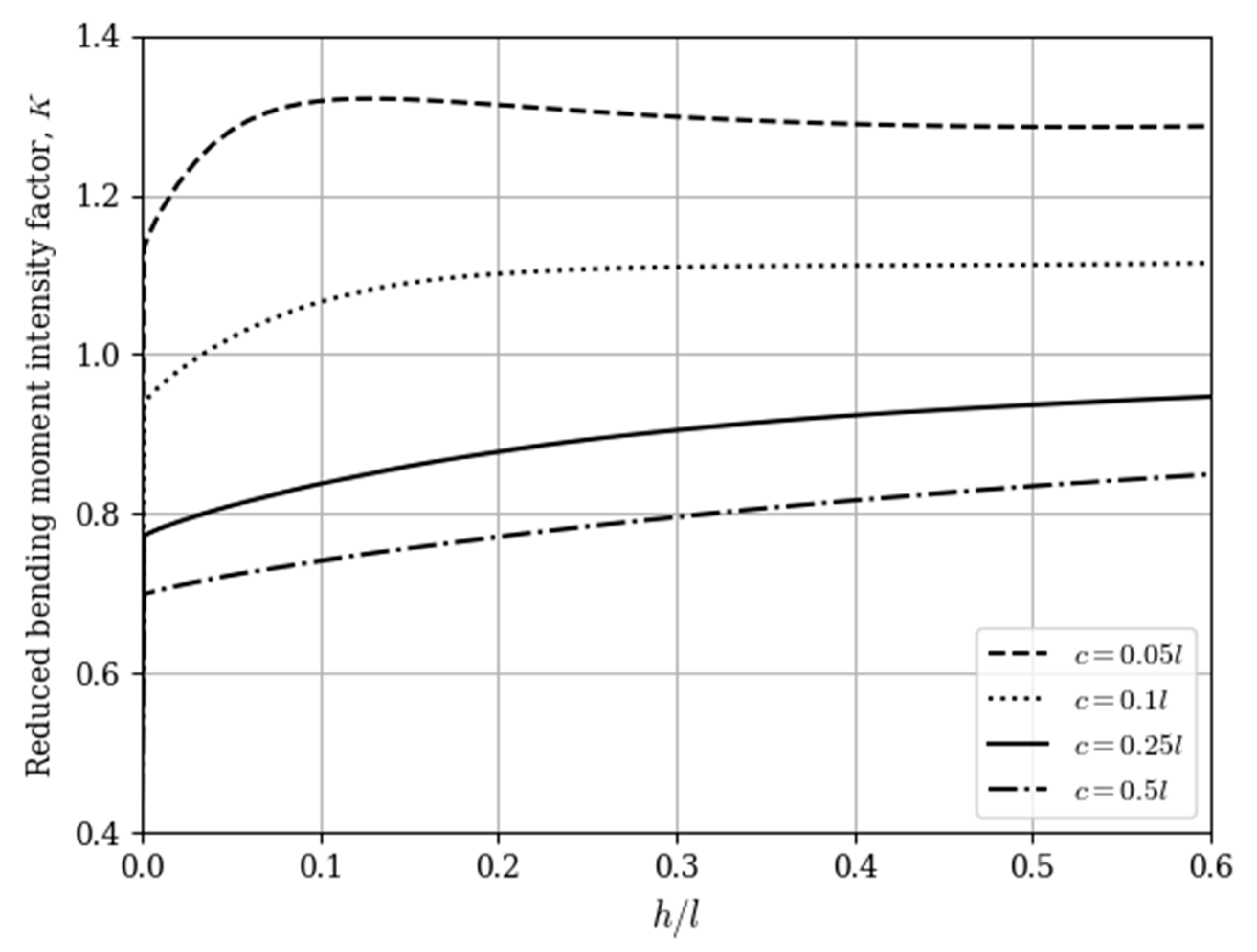
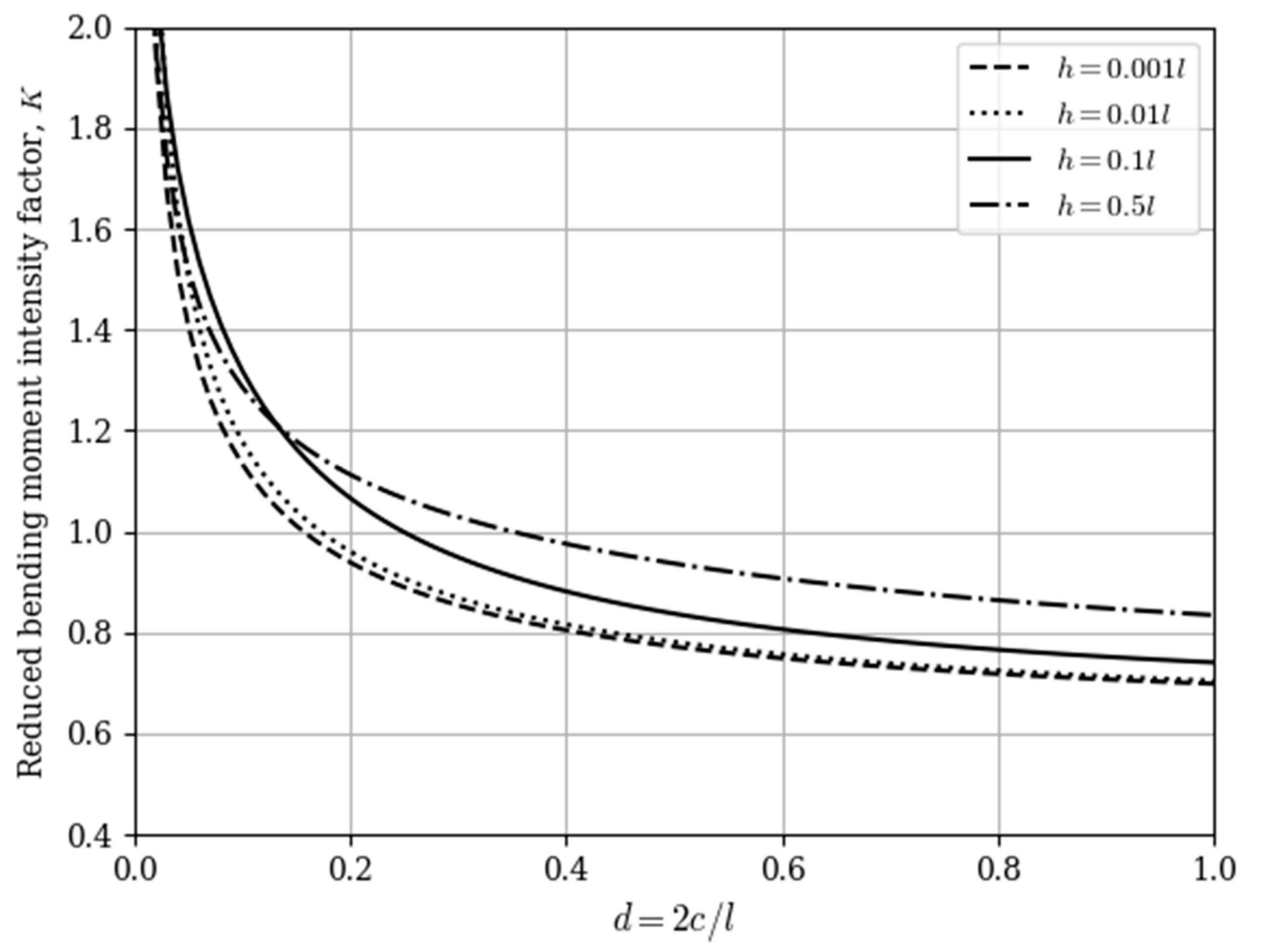
Figure 2, Figure 3 and Figure 4 illustrate the graphical dependences of the reduced moment intensity factor   K = K M M l for the inner crack tip on various geometrical and mechanical parameters, where K M is defined by (22). Python′s matplotlib library is used to visualize the data. Values of the moment intensity factor for the outer crack tip are not shown because they are always smaller than corresponding values for the inner crack tip. That is, crack propagation occurs first towards each other.
All the calculations are carried out with an absolute error not exceeding 0.0001. The accuracy was checked by comparing the results for N and 2N nodes of the mechanical quadrature method.

4. Conclusions

From Figure 3 and Figure 4 it follows that the dependences of the bending moment intensity factor on the geometrical parameters have the same character as for the single-layer plate [1,5]. Therefore, a layered plate with two coaxial cracks under pure bending is weaker than the same plate with one crack.
Figure 2 indicates that the plates for which the shear modulus in transverse direction of inner layer is greater than the one of outer layers, are stronger. It is also possible to obtain the optimum ratio of layer thicknesses (in our calculated case it is h 1 0.7 h ), at which the bending moment intensity factor is the lowest.
Note that in the partial cases (materials of all layers are the same, infinite distance between the crack tips, infinitely thin plate) obtained values of the reduced bending moment intensity factor are the same as in [1,5,15].
Built dependencies allow us to make recommendations on the optimum structure of plate construction units and indicate the bending modes of their safe operation.

Author Contributions

Conceptualization, M.D., R.S. and V.O.; methodology, V.O.; software R.S. and O.B.; validation, M.D., V.O. and O.B.; formal analysis M.D. and R.S.; investigation, O.B.; resources, V.O. and O.B.; data curation, V.O. and O.B.; writing—original draft preparation, M.D., V.O. and O.B.; writing—review and editing, M.D., V.O., R.S. and O.B.; visualization R.S.; supervision, M.D.; project administration, V.O. All authors have read and agreed to the published version of the manuscript.

Funding

This research received no external funding.

Institutional Review Board Statement

Not applicable.

Informed Consent Statement

Not applicable.

Data Availability Statement

Not applicable.

Conflicts of Interest

The authors declare no conflict of interest.

References

  1. Murakami, Y. (Ed.) Stress Intensity Factors Handbook; Oxford etc. Pergamon Press: Oxford, UK, 1987; Volume 2, 1456p. [Google Scholar]
  2. Zehnder, A.T.; Viz, M.J. Fracture mechanics of thin plates and shells under combined membrane, bending, and twisting loads. Appl. Mech. Rev. 2005, 58, 37–48. [Google Scholar] [CrossRef] [Green Version]
  3. Corbani, S.; Miranda, A.C.; Martha, L.F.; Castro, J.T.; Carter, B.J. Investigations in a cracked plate under bending. Mecánica Comput. 2010, 29, 5163–5171. [Google Scholar]
  4. Bäcker, D.; Kuna, M.; Häusler, C. Eigenfunctions of crack problems in the Mindlin plate theory. ZAMM—J. Appl. Math. Mech. 2015, 95, 763–777. [Google Scholar] [CrossRef]
  5. Opanasovych, V.K.; Seliverstov, R.H. Bending of a plate with two identical collinear rectilinear cracks according to the theory of Reissner. Mater. Sci. 2001, 37, 59–64. [Google Scholar] [CrossRef]
  6. Yatsyk, I. Reissner′s plate bending containing periodic system of collinear through-the-thickness cracks taking into account contact region width of their faces (in Ukrainian). Visnyk Lviv Univ. Ser. Mech.-Math. 2010, 73, 155–164. [Google Scholar]
  7. Sulym, H.; Opanasowych, W.; Jacyk, I. Zginanie płyty Reissnera ze szczelinami przy uwzglednieniu szerokosci strefy kontaktu brzegów szczelin. Acta Mech. Autom. 2011, 5, 85–93. [Google Scholar]
  8. Maksymovych, O.; Illiushyn, O. Stress calculation and optimization in composite plates with holes based on the modified integral equation method. Eng. Anal. Bound. Elem. 2017, 83, 180–187. [Google Scholar] [CrossRef]
  9. Liu, Z.; Chen, X.; Yu, D.; Wang, X. Analysis of semi-elliptical surface cracks in the interface of bimaterial plates under tension and bending. Theor. Appl. Fract. Mech. 2018, 93, 155–169. [Google Scholar] [CrossRef]
  10. Hsieh, M.C.; Hwu, C. Anisotropic elastic plates with holes cracks inclusions subjected to out-of-plane bending moments. Int. J. Solids Struct. 2002, 39, 4905–4925. [Google Scholar] [CrossRef]
  11. Yankovsky, A.P. Refined model of thermo-elastic-plastic bending of layered plates of regular structure. II. Modeling problems. J. Math. Sci. 2021, 253, 122–135. [Google Scholar] [CrossRef]
  12. Khosravani, M.R.; Zolfagharian, A.; Jennings, M.; Reinicke, T. Structural performance of 3D-printed composites under various loads and environmental conditions. Polim. Test. 2020, 91. [Google Scholar] [CrossRef]
  13. Shao-Tzu, C.; Li, H. Boundary-based finite element method for two-dimensional anisotropic elastic solids with multiple holes and cracks. Eng. Anal. Bound. Elem. 2017, 79, 13–22. [Google Scholar] [CrossRef]
  14. Khezri, M.; Rasmussen, K.J.R. An energy-based approach to buckling modal decomposition of thin-walled members with arbitrary cross sections, Part 1: Derivation. Thin-Walled Struct. 2019, 138, 496–517. [Google Scholar] [CrossRef]
  15. Berezhnytsky, L.T.; Delyavskyy, M.V.; Rudnytsky, I.I. Bending of a layered plate with a crack at the arbitrary distribution of displacements over the thickness (in Russian). Strength Mater. 1984, 10, 68–72. [Google Scholar]
  16. Berezhnytsky, L.T.; Delyavskyy, M.V.; Mazurak, L.P. Account of the asymmetry of tangential stresses for the bending of layered plates with cracks (in Russian). Int. Appl. Mech. 1985, 21, 81–86. [Google Scholar]
  17. Opanasovych, V.K.; Seliverstov, R.H. A bending of a layered plate with two parallel unshifted cracks (in Ukrainian). Mech. Eng. 2002, 6, 17–19. [Google Scholar]
  18. Panasyuk, V.V.; Savruk, M.P.; Datsyshyn, A.P. Stress Propagation Near the Cracks in Plates and Shells (in Russian); Naukova Dumka: Kiev, Ukraine, 1976. [Google Scholar]
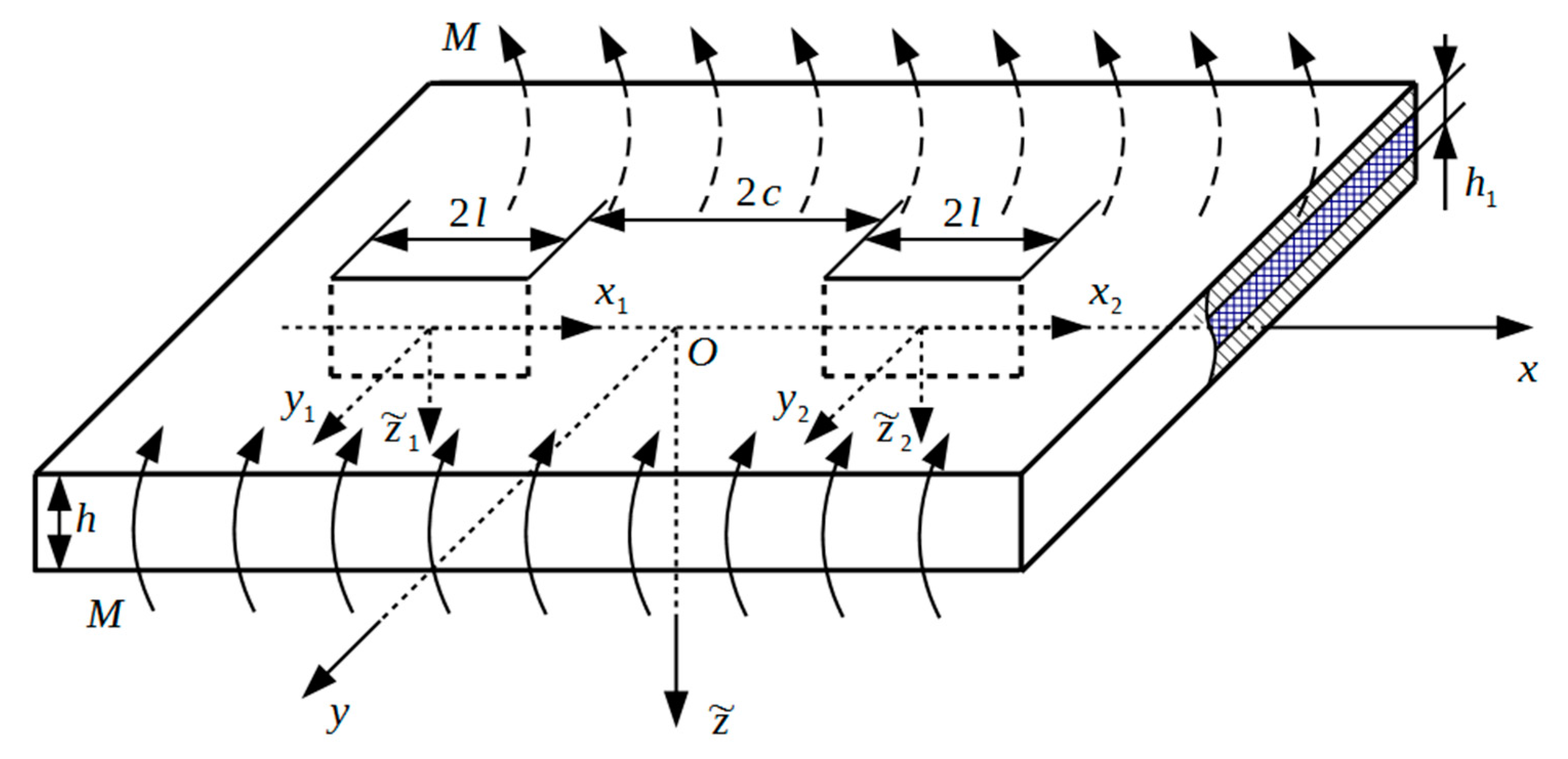
Figure 1. Plate geometries and load scheme.
Applsci 11 02859 g001
Figure 2. Dependence of the reduced moment intensity factor for inner crack tip on the layer thickness ratio γ = h 1 / h at h / l = 2 c / l = 1 and various values of shear modulus ratio β = G 2 / G 1 .
Applsci 11 02859 g002
Figure 3. Dependence of the reduced moment intensity factor for inner crack tip on the plate-thickness-to-crack-length ratio h / l at β = G 2 / G 1 = 0.5 , γ = h 1 / h = 0.8 and various distances between cracks tips.
Applsci 11 02859 g003
Figure 4. Dependence of the reduced moment intensity factor for inner crack tip on the distance between crack tips d = 2 c / l at β = G 2 / G 1 = 0.5 , γ = h 1 / h = 0.8 and various values of plate-thickness-to-crack-length ratio.
Applsci 11 02859 g004
Table 1. Mark meanings.
MarkMark Meaning
h plate thickness
E 1 Young′s modulus of outer layers in the plane of isotropy
E 2 Young′s modulus of inner layer in the plane of isotropy
ν 1 Poisson′s ratio of outer layers in the plane of isotropy
ν 2 Poisson′s ratio of inner layer in the plane of isotropy
G 1 shear modulus of outer layers in the transverse direction
G 2 shear modulus of inner layer in the transverse direction
2 l crack length
x j coordinates of the center of j-th crack
2 c distance between inner tips of cracks
M bending loads at infinity
M y bending moments
H x y twisting moments
Q x , Q y shear forces
u ( k ) , v ( k ) , w ( k ) components of displacement vector in the k-th layer
σ x ( k ) , σ y ( k ) , τ x y ( k ) , τ z ˜ x ( k ) , τ z ˜ y ( k ) components of stress tensor in the k-th layer
W ( x , y ) , F ( x , y ) , Ω ( x , y ) unknown functions
z complex variable
Φ ( z ) , Ψ ( z ) complex potentials
K i ( x ) Macdonald function of i-th order
K M ± bending moment intensity factor
K reduced moment intensity factor
Publisher’s Note: MDPI stays neutral with regard to jurisdictional claims in published maps and institutional affiliations.