Article

Numerical Investigation on Crack Propagation for a Central Cracked Brazilian Disk Concerning Friction

1
Key Laboratory of Deep Underground Science and Engineering, Ministry of Education, College of Architecture and Environment, Sichuan University, Chengdu 610065, China
2
College of Mechanical and Electrical Engineering, Xichang University, Xichang 615013, China
3
Failure Mechanics and Engineering Disaster Prevention and Mitigation Key Laboratory of Sichuan Province, Sichuan University, Chengdu 615065, China
*
Authors to whom correspondence should be addressed.
Appl. Sci. 2021, 11(6), 2839; https://doi.org/10.3390/app11062839
Submission received: 18 February 2021 / Revised: 9 March 2021 / Accepted: 18 March 2021 / Published: 22 March 2021
(This article belongs to the Section Civil Engineering)

Abstract

:
This paper concerns the effect of friction on crack propagation for the centrally cracked Brazilian disk under diametric forces by using a modified finite element method. It shows that the mode II stress intensity factor decreases obviously with the increase of friction after the crack is closed, while friction has no influence on the stress intensity factor of mode I and T-stress. Meanwhile, there are some significant influences on the crack propagation due to the change of the friction after the crack is closed with the appropriate loading angle and relative length of the crack. When T-stress is positive, the effect of friction becomes obvious and the crack propagation angle increases with a lager friction coefficient. With increasing the friction, the deviation for the crack propagation trajectory increases and the curvature of path decreases, which may lead to the change of crack type. Additionally, the larger relative crack length can amplify the effect of friction, which is similar to the loading angle.

1. Introduction

Crack defects are often distributed in brittle media, including concretes and rocks. Under the action of complex external loads, these defects cause local cracking and form macroscopic cracks, resulting in the decrease of strength and stiffness of the medium, which may reproduce and extend to complete penetration. In order to keep the integrity and safety of structures, the study on crack initiation and growth is of guiding significance. Meanwhile, the stress intensity factors (SIFs) and T-stresses, as important fracture parameters of the linear elastic fracture mechanics (LEFM) used to evaluate the fracture performance of brittle materials, also have important practical significance in engineering fracture problems. Additionally, the central crack Brazilian disc has been widely used due to its convenience in changing the fracture mode of crack [1,2,3].
In any case, rough brittle materials with many closed cracks are subjected to the effect of the friction in actual underground engineering such as tunnel operation and gas exploration. Under these conditions, the fracture parameters, crack initiation and propagation of brittle materials under compressive-shear loading would be greatly affected. Therefore, in order to better understand the failure mechanisms and propagation behavior concerning the effect of friction of brittle materials such as rocks, some experimental tests were performed in this area. Erarslan et al. [4] carried out composite fracture loading by using the cracked chevron notched Brazilian disk (CCNBD) specimens made of three kinds of rock materials.
In the test, a displacement gauge was used to measure the displacement of radial compression in the crack tip. Moreover, this experimental result showed that in the case of compression-shear fracture, both the initiation angle and the initiation point of the crack would be affected. Nemat-Nasser and Horii [5] described compression-shear experiments of uniaxial compression concerning frictional contact. In order to control friction, the brass sheets or thin Teflon sheets were inserted into the crack. Their results showed that the specimen failure was caused by the axial splitting rather than shear failure and the crack propagated in the direction of the applied load, which was also demonstrated by the maximum tangential stress (MTS) criterion. Meanwhile, Cotterell [6] and Hoek et al. [7] found a similar phenomenon through a range of experiments. Furthermore, compression-shear experiments were reported as well on the law of crack propagation [8,9,10]. Although the experimental results could provide guidance in other directions, their implementation was usually limited by external conditions such as time-consuming and complex processes. Additionally, the cracks were not easy to contact due to the crack width [4] and some physical parameters such as friction coefficient could not be controlled easily. Therefore, theoretical method has attracted growing interest because of its convenience and reliability.
In the past few years, on the basis of previous reports by Dong [1] and Hua [11], Li [12] and Tang [13] analyzed the stress field inside the centrally cracked Brazilian disk (CCBD) specimen under different loading conditions when the crack surface contacted through the theoretical study. Furthermore, an analytical formula was obtained for calculating the Mode II SIFs in CCBD specimens under different loading conditions by using the weight function method (WFM). Meanwhile, prompted by some theoretical researches on T-stress [14,15], Tang [16] proved that the friction had no effect on T-stress in CCBD specimens subjected to diametric forces and confining pressure. Spagnoli et al. [17] discussed the effect of roughness between crack surfaces and friction coefficient on the dimensionless Mode II stress intensity factor and crack initiation angle using Distributed Dislocation Technique (DDT) and MTS criterion.
Currently, due to the complex boundary conditions, numerical approaches are increasingly used. For instance, Hua et al. [11,16] and Zhou et al. [18] accurately calculated the stress intensity factors and T-stresses for CCBD under concentrated force and confining pressure through conventional finite element method (FEM). Huang et al. [19] and Hou et al. [20] calculated those fracture parameters under different confining pressure coefficients based on the improved finite element method. Furthermore, various methods were reported for the fracture propagation under complex conditions. Lim et al. [21] developed a technique of automatic local meshing based on finite element method to simulate mixed-mode fracture growth automatically. Erarslan et al. [4] and Haeri et al. [22] combined finite element method and MTS criterion to simulate the crack propagation from pure I to compression-shear fracture of Brazilian disk specimens. These results had a high matching degree with the experimental outcome. Meanwhile, numerical methods such as generalized particle dynamics, unconventional state-based peridynamics and phase field method, combining MTS and Mohr–Coulomb criterion, would simulate crack growth of different modes fracture [23,24,25]. Belytschko et al. [26] also proposed a convenient numerical method introducing an enrichment function to deal with complex practical problems, which was called as extended finite element method (XFEM). Based on XFEM, Dolbow et al. [27] combined traditional MTS criterion and LATIN method to explore the propagation of crack concerning frictional contact. The results showed that the simulated extension path was consistent with the experimental observations of Nemat-Nasser and Horii [5].
However, in the simulation of two-dimensional crack propagation problem, XFEM usually adopts first-order elements with weak analytical performance [28], which might result in inaccurate outcome when simulating compression-shear fracture. Moreover, there are few reports on fracture parameters and propagation of crack, considering the effect of friction for CCBD specimens through the general numerical methods. Therefore, prompted by an improved numerical method proposed by Huang et al. [19], a modified finite element method (MFEM) is developed. The MFEM involving the behavior of the frictional contact is based on FEM using user defined subroutine. Additionally, the purpose of this study is to investigate the influence of friction on fracture parameters and propagation of crack for CCBD specimens under radial compression forces when the crack surface is in contact, which is usually difficult to be studied through experimental tests.
The framework of this investigation is briefly summarized as follows. Section 2 mainly elaborates the principle of the interaction integral for MFEM and the generalized MTS (GMTS) criterion. Section 3 mainly illustrates when the crack surface is in contact, the analytical formula of SIFs and T-stresses concerning the friction by using the WFM for CCBD. Section 4 introduces some calculation examples for CCBD specimens about the effects of friction on fracture parameters (mainly SIFs and T-stresses) and crack propagation. Section 5 summarizes the conclusion of the whole work.

2. Integral and Crack Propagation Criteria

2.1. Two-Dimensional Interaction Integral with MFEM

The energy integral I, called the interaction integral, includes the contour Γ around the crack tip, which is a highly accurate method that has emerged in recent years to solve the two-dimensional fracture problem [29,30]. It is based on the quasi-static derivation process, assuming that the material has the characteristics of small deformation, linear elasticity and continuity.
I = Γ [ W δ 1 j σ i j ( a c t ) ( u i ( a u x ) ) x σ i j ( a u x ) ( u i ( a c t ) ) x ] n j d Γ
where nj is the unit external normal vector of the contour Γ. In addition, the form of the strain energy density W for the interaction integral is as follows:
W = σ i j ( a c t ) ε i j ( a u x ) = σ i j ( a u x ) ε i j ( a c t )
In finite element theory, it is not easy to solve the infinitesimal contour integral near the crack tip. In order to facilitate the calculation in practical applications, the interaction integral formula is usually converted into an equivalent surface integral as shown in Figure 1. There is a new contour C set outside the contour Γ, which makes the region S closed. Then, through the divergence theorem, the line integral of Equation (1) can be further written as below [19,27,31]
I = S [ σ i j ( a c t ) ( u i ( a u x ) ) x + σ i j ( a u x ) ( u i ( a c t ) ) x W δ 1 j ] q x d S C + + C [ σ i 2 ( a c t ) ( u i ( a u x ) ) x + σ i j ( a u x ) ( u i ( a c t ) ) x ] q m j d C
where q is defined as the variable weight function, which takes the value of 1 in region S and 0 in other places. In addition, there is a unit normal vector mj, which is perpendicular to profile C, as shown in Figure 1.
Therefore, the stress intensity factors and T-stress in the real fields can be obtained by selecting the appropriate auxiliary fields. Because the selection of the stress intensity factors and T-stresses in the auxiliary fields is different for the interaction integral, the selection of auxiliary fields in this paper is consistent with that of the Refs. [19,32,33,34].
When the integral path Γ approaches the tip of crack, the relationship between the stress intensity factors and the interaction integral I can be obtained as below
I = 2 E * ( K I K I ( a u x ) + K II K II ( a u x ) )
where E* is defined as follows:
E * = { E , E / ( 1 ν 2 ) , ( plan   stress ) ( plan   strain )
If the SIFs of the auxiliary fields satisfy special conditions [19], the SIFs of the actual fields can be derived as
K I = E * 2 I ( K I ( a u x ) = 1 , K II ( a u x ) = 0 )  
K II = E * 2 I ( K I ( a u x ) = 0 , K II ( a u x ) = 1 )
Similarly, T-stress can also be derived by interaction integral and its expression is as follows:
T = E * f I
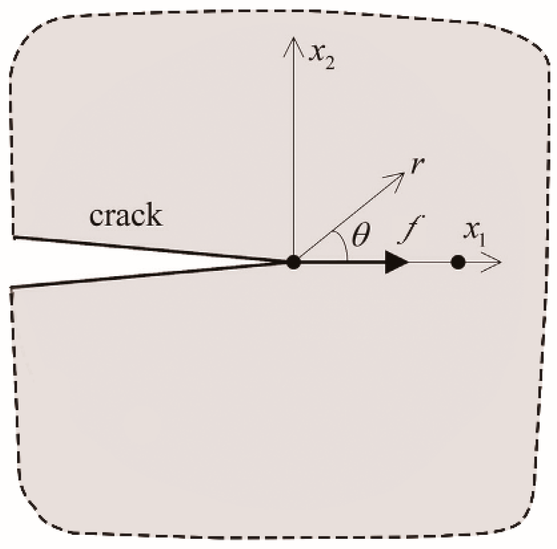
where f is defined as a line load, which is applied on the crack propagation plane and along the line of the crack, as shown in Figure 2.
In order to facilitate subsequent observation and comparison, the dimensionless forms of the SIFs and T-stress are adopted as [11,14]
K I = P π B R π a K I * , K II = P π B R π a K II * , T = P π B R T *

2.2. Criteria for Crack Propagation

The crack initiation and propagation of brittle materials such as rocks and ceramics in engineering are often predicted by appropriate mixed mode fracture criterion. Currently, the common mixed mode fracture criteria have always been the focus of research, e.g., the maximum tangential stress criterion [35], the criterion of local symmetry [5,36], the minimum strain energy density criterion [37] and the maximum energy release rate criterion [38]. Additionally, the related literatures [5,22,27] show that the MTS criterion or the local symmetry criterion could be used to accurately simulate the compression-shear mixed mode propagation process consistent with the experimental outcome under appropriate conditions, which confirms the accuracy of the MTS criterion and extends its applicable range of MTS fracture criterion. However, prompted by related researches [15,16,25,39,40,41], T-stress has a significant effect on propagation angle of the crack, while the traditional MTS criterion only contains the singular term, which would inevitably make the generalized MTS criterion considering the influence of T-stress more accurate in predicting the propagation path. Therefore, the GMTS criterion would be adopted to predict the initiation and propagation trajectory of the crack concerning the frictional contact in this work.
According to Hua et al. and Tang [16,41], the tangential stress component of the linear elastic stress field around the crack tip can be written as:
σ θ θ = 1 2 π r cos θ 2 [ K I cos 2 θ 2 3 2 K II sin θ ]   + T sin 2 θ
where r and θ are the polar coordinates of the crack tip.
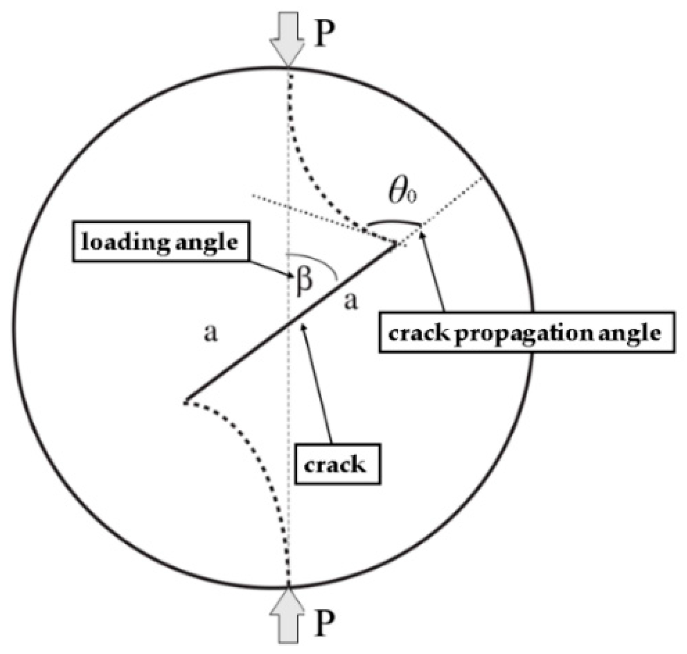
According to the theory of the criterion, the crack still propagates in the direction of the maximum tangential stress around the crack tip. In addition, the angle of the fracture initiation (Figure 3) can be obtained from the following forms
σ θ θ θ | θ = θ 0 = 0
[ K I sin θ 0 + K II ( 3 cos θ 0 1 ) ] 16 3 T 2 π r c cos θ 0 sin θ 0 2 = 0
where rc is a material constant for brittle materials and represents a critical distance from the crack tip. In addition, rc can be expressed as
r c = 1 2 π ( K I C σ t ) 2
where KIC is the fracture toughness of the pure mode I; σt is the tensile strength of the brittle material.
Meanwhile, the equivalent stress intensity factor Keq can be adopted and the crack begins to expand when it is greater than or equal to KIC [42]. The equivalent stress intensity factor can be expressed as below:
K e q = cos θ 0 2 [ K I cos 2 θ 0 2 3 2 K II sin θ 0 ] + 2 π r c T sin 2 θ 0

3. The WFM Concerning Frictional Contact

It is assumed that the studied Brazilian disc obeys the assumptions of small deformation, isotropic and linear elasticity. According to the research of Dong [1] and Hua [11,14], the expressions of the stress intensity factors and T-stress for CCBD under diametrical forces without involving the friction can be obtained.
K I = 0 a h 1 ( x , a ) σ θ ( x ) d x
K II = 0 a h 2 ( x , a ) τ r θ ( x ) d x
T = 0 a h 3 ( x , a ) σ θ ( x ) d x σ θ | r = a + σ r | r = a
where h 1 ( x , a ) , h 2 ( x , a ) , h 3 ( x , a ) , obtained by the boundary configuration method, are the weight function independent of the loading condition. σ r , σ θ and τ r θ are the stress components for the uncracked disk. In addition, the detailed formulas mentioned above can be found in the Refs. [43,44]
When the crack changes from pure mode I to mixed mode, the stress intensity factors and T-stress of CCBD can be further written as follows:
K I = σ π a [ f 11 + 2 i = 1 n A 1 i f 1 i α 2 ( i 1 ) ]
K II = 2 σ π a i = 1 n A 2 i f 2 i α 2 ( i 1 )
T = σ f 1 + 2 σ i = 1 n ( A 2 i ( θ ) f i A 2 i ( θ ) A 1 i ( θ ) ) α 2 ( i 1 )
where σ is the normal stress, where σ = P/(πBR). The relative length of crack α equals a/R. fji and Aji (j = 1, 2 and i = 1, 2, …, n) are the coefficients [1].
However, the situation is much more complicated when the crack changes from pure mode II to compression-shear state so that the crack surface is closed. At this time, with the increase of the loading angle, the boundary of the crack surface may overlap or even cross, which would cause the normal pressure and friction on the crack surface [2]. In addition, when the crack surface is closed, CCBD is equivalent to a crack-free disk. The central crack of the CCBD is assumed to be a linear crack that is in contact under radial forces. The shear stress of crack surface changes due to the friction generated by the contact [45]. Assuming that the friction coefficient is μ, through the Coulomb friction law, the changed shear stress τ r θ can be obtained as follows [46]:
τ r θ = τ r θ + μ σ θ
where shear stress τ r θ should be greater than the friction, otherwise the crack would be in the state of cementation.
Meanwhile, the formula for the mode II stress intensity factor considering friction can be further derived from Equation (16) as bellow
K II = 0 a h 2 ( x , a ) τ r θ ( x ) d x
According to the above analysis, the friction generated by contact will not affect the stress components ( σ r and σ θ ) except the shear stress ( τ r θ ). Therefore, the formulas for mode I stress intensity factor ( K I ) and T-stress ( T ), involving the behavior of the friction, are consistent with those without considering the friction. The compression-shear crack surfaces cannot be intercalated due to the consideration of contact. Therefore, the KI in compression-shear fracture is taken as 0 [17]. Therefore, the mode I SIF concerning the frictional contact can be sorted into the following form
K I = { K I , 0 , ( K I > 0 ) ( K I 0 )
Then, the dimensionless intensity factors and T-stress can be respectively written as bellow:
K I * = { K I σ π a = ( 1 t ) f 11 + 2 i = 1 n A 1 i f 1 i α 2 ( i 1 ) , 0 , ( K I > 0 ) ( K I 0 )
K II * = K II σ π a = 2 i = 1 n ( μ A 1 i + A 2 i ) f 2 i α 2 ( i 1 ) + μ f 21
T * = T ( 1 α ) σ = σ f 1 + 2 σ i = 1 n ( A 2 i ( θ ) f i A 2 i ( θ ) A 1 i ( θ ) ) α 2 ( i 1 )
The derived Equations (24)–(26) are the basis of GMTS criterion, which could establish the mathematical model for crack propagation.

4. Results and Discussion

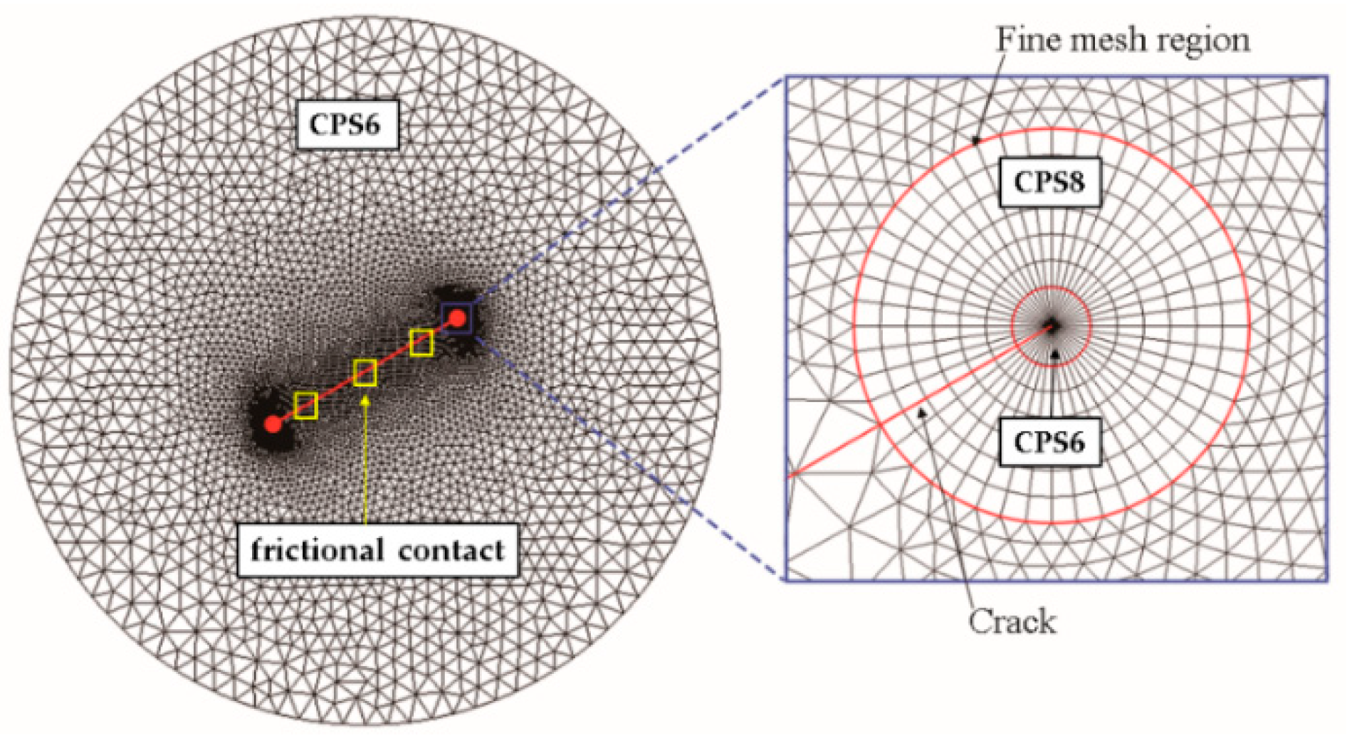
The fracture test under radial forces was numerically performed using the MFEM. The advantage of the MFEM, implemented through the ABAQUS and PYTHON, is that it is based on the FEM using user defined subroutine, combining the GMTS criterion with the interaction integral method. During the simulation (Figure 4), the propagation of the studied crack is obtained by the elongation of many small cracks and its successful implementation also depends on the overall remeshing technique [47,48] and the method of incremental crack propagation [21,49]. In addition, considering the influence of mesh size h and increment of the crack propagation length i on the calculation accuracy, both h and i adopted the recommended values (generally, half of the internal parameters is chosen as the h and h / 2 i < h ) [19,25,49]. The combination of these technologies can make the MFEM have high accuracy and versatility for two-dimensional linear elastic problems under various loads. Meanwhile, the two-dimensional and isotropic CCBD numerical model (Figure 5), concerning the friction contact on the crack surfaces, was adopted, which prevented the elements of crack surface from infiltrating each other. In addition, around the crack tip of the model, the second order plane stress grids of six-node element (CPS6) and eight-node element (CPS8), which are set with singularity, are used to ensure the accuracy of the calculation. In addition, due to the well crack closed state and crack growth paths obtained by inserting the metal sheets, the model parameters (Table 1), which come from the mixture of fine sand, moderate pozzolanic cement and water performed by Haeri et al. [22], are used for simulation. For the sake of simplicity, only the friction coefficient, loading angle and relative crack length were changed in the following work, while other model parameters remained fixed. The detailed calculation results and discussions of several case studies about the effects of friction contact on fracture parameters and crack propagation in this section are as follows.

4.1. SIFs and T-Stress Concerning Frictional Contact

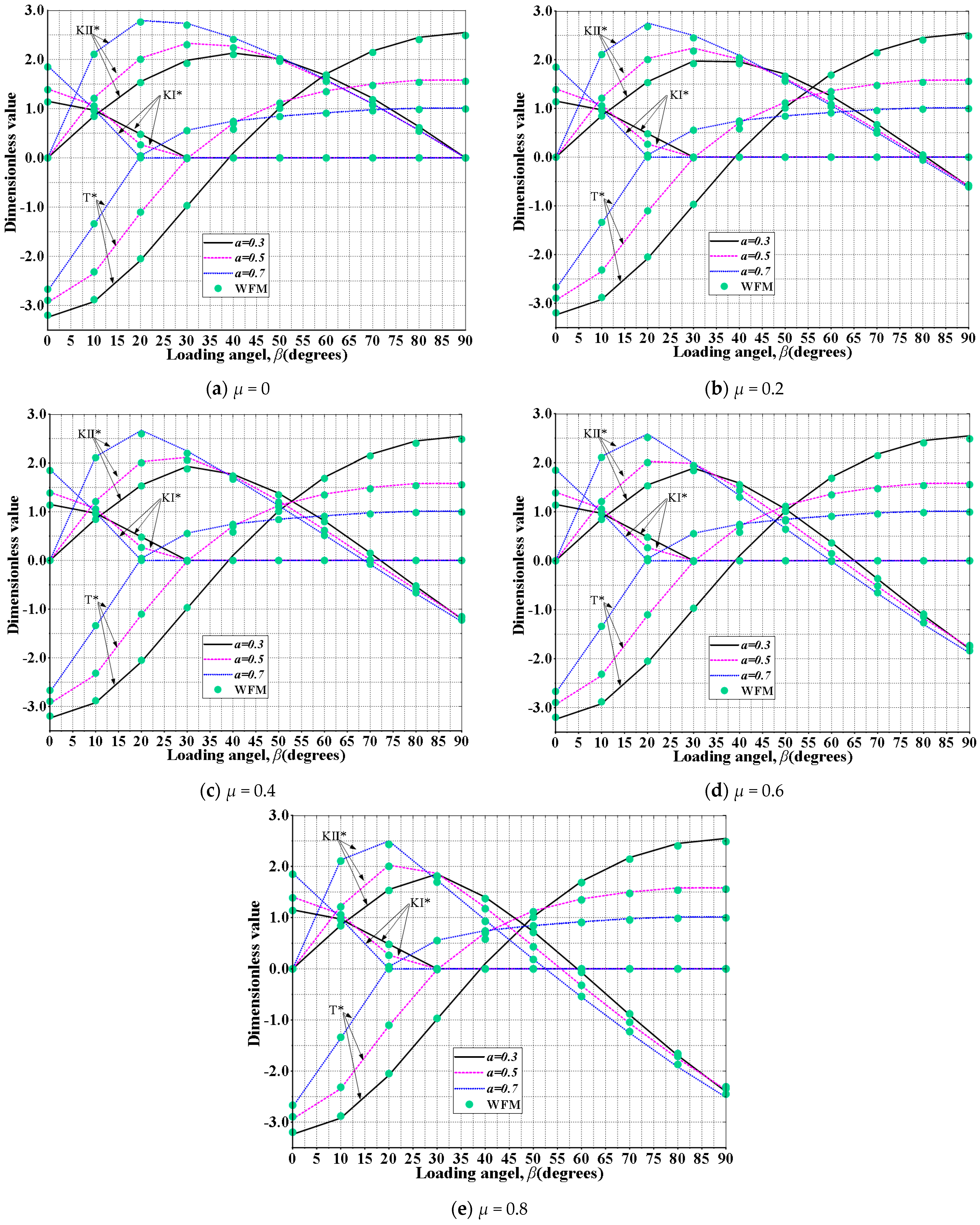
The purpose of this section is to study the effect of friction on stress intensity factors and T-stresses at the onset of fracture. Figure 6 clearly shows the dimensionless K and T, calculated by the WFM and MFEM, versus the loading angle with different friction coefficients (μ = 0, 0.2, 0.4, 0.6 and 0.8) and relative lengths of the crack (α = 0.3, 0.5 and 0.7). By comparison, the results between MFEM and WFM have strong consistency with a maximum error within 3%, which shows that the proposed MFEM is reliable.
First, some variation rules of the stress intensity factors and T-stress with different loading angles and relative crack lengths can be observed, which is similar to the research conclusions of some scholars [14,16,20,25]. Meanwhile, when the crack is closed, the setting the frictional contact makes the normalized mode I SIF KI* = 0, while the KI* and T* remain the same trends no matter what the friction coefficient is. These results indicate that the SIF of mode I and T-stress are indeed independent of friction, which is consistent with the conclusions predicted by WFM.
However, it can be seen from the Figure 6, the friction has a significant influence on the mode II stress intensity factor when the crack is closed. In addition, as increasing the friction coefficient μ, the KII* decreases obviously when relative length of crack α and loading angle β have the certain values. For example, with the friction coefficient increases from 0 to 0.8, for the loading angle of 60°, the KII* decreases 120.7% when α = 0.5. In addition, with the larger α and β, the effect of friction is more significant as the amount of increase in friction coefficient is constant. For example, as the friction coefficient increases from 0 to 0.6, the KII* decreases 14.6% when α = 0.3 and β = 40°, while the KII* decreases 58.5% for α = 0.5 and β = 50°. It is well known that the crack is in a viscous state when the KII* is less than 0 [50]. Figure 6 also shows that when μ is equal to 0 (the crack surface is smooth enough), the crack would not be in a sticky state from beginning to end with the loading angle increases from 0 to 90°. However, with a larger friction coefficient, the loading angle corresponding to KII* = 0 decreases gradually, which indicates that the crack is in a viscous state earlier under the condition. At the same time, the larger loading angle and relative crack length will make this phenomenon more obvious.
In general, the foregoing results show that the friction has a significant effect on the mode II SIF after the crack is closed, which indicates that it is necessary to consider influence of the friction in the real contact state, but has no influence on the stress intensity factor of mode I and T-stress.

4.2. Crack Initiation and Propagation Concerning Frictional Contact

4.2.1. Crack Initiation

The effects of friction force, relative crack length and loading angle on crack initiation and propagation of CCBD specimens are studied in this section. For some of the reasons illustrated in Section 2.2, the generalized MTS criterion, considering the influence of T-stress, would be used to predict the initiation and propagation of the crack. It can be seen from the conclusion in Section 4.1 that a large friction coefficient will cause the crack to be in the adhesive zone earlier [50], which makes the normal propagation of the crack gradually difficult [16]. Meanwhile, the phenomenon is more obvious under larger relative length of crack α and loading angle β. However, many literatures have also shown some experimental results of the instability of compression-shear cracks, e.g., (1) the shifting phenomenon of crack initiation point [4,22], which indicates that the crack initiation point would shift to the center of the crack at a larger loading angle; (2) the multi-branching phenomenon of the crack [51], which generally occurs in compression-shear fracture under a certain loading angle. Therefore, in order to explore the law of crack initiation and propagation stably, the friction coefficient μ is equal to 0, 0.3 and 0.6 respectively and the relative crack length α = 0.3 and 0.5 with the loading angle β ≤ 60°.
The crack propagation angle θ0, which is defined as positive in the counterclockwise direction, versus the loading angle β is compiled in Figure 7. It can be seen that there is a certain amount of the deviation between the crack propagation angle predicted by GMTS criterion and that predicted by MTS criterion in most regions. That is because KI, considering friction contact, is always 0 after the crack surface is closed and T-stress has a significant effect on propagation angle of the crack [40]. Meanwhile, there are some regions of loading angle with gradually decreasing the above deviation, because the T-stress at this stage changes from negative to positive, as shown in Figure 6. On the whole, the crack propagation angle predicted by GMTS increases with the increase of β. When T-stress is positive, the effect of friction becomes obvious and the crack propagation angle increases with the increase of friction. Further, a larger relative crack length magnifies the above effect.

4.2.2. Crack Propagation Trajectory

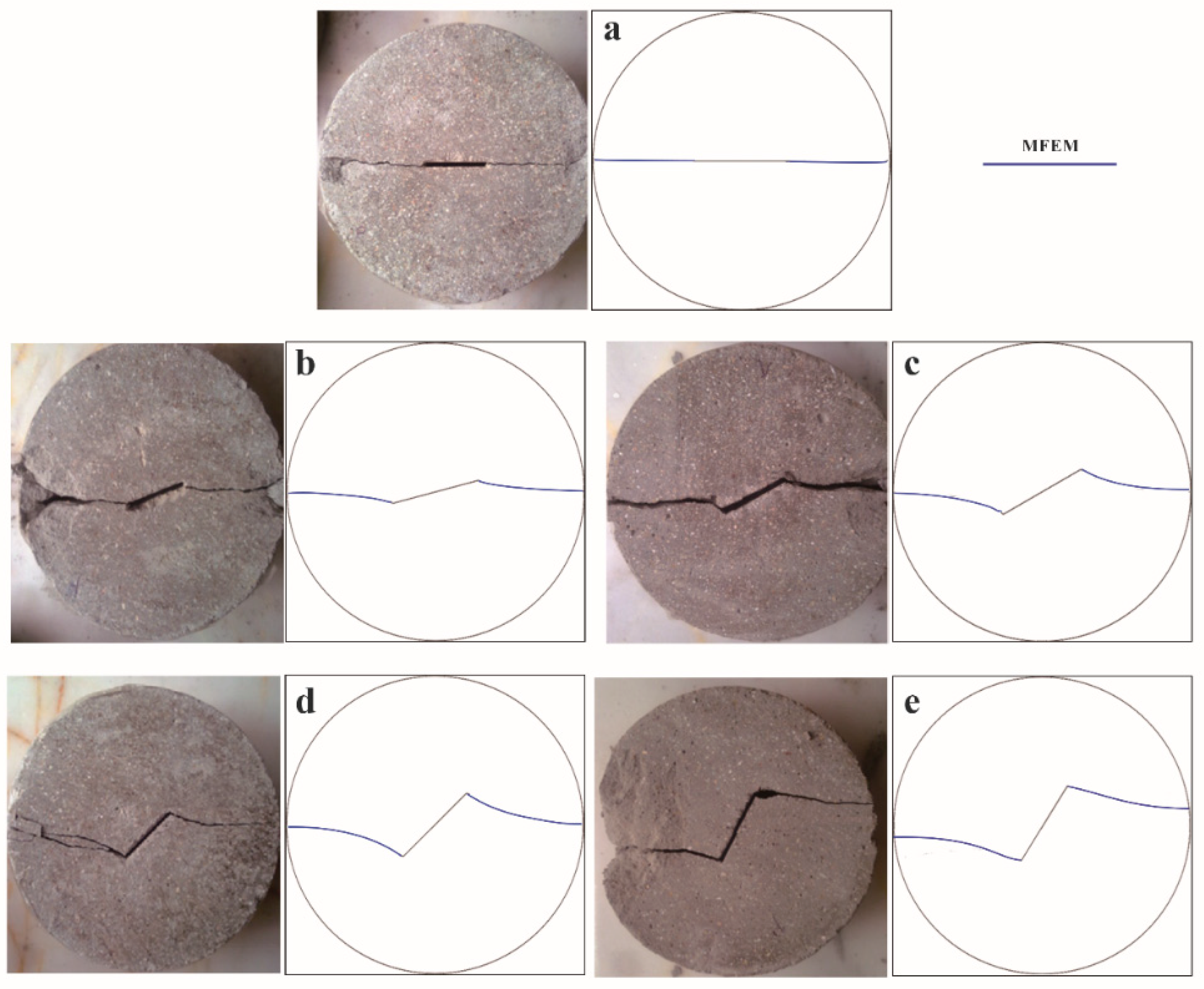
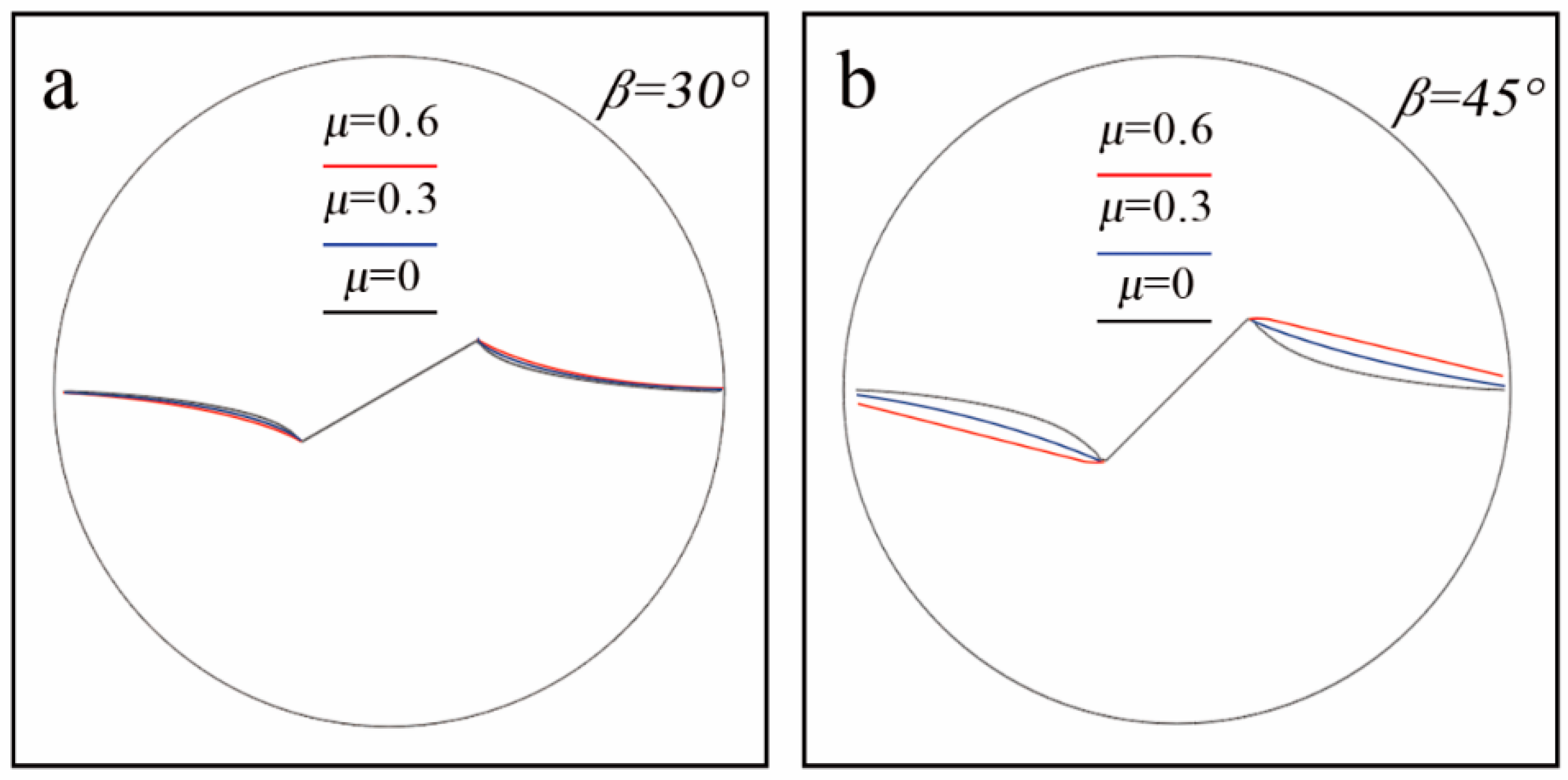
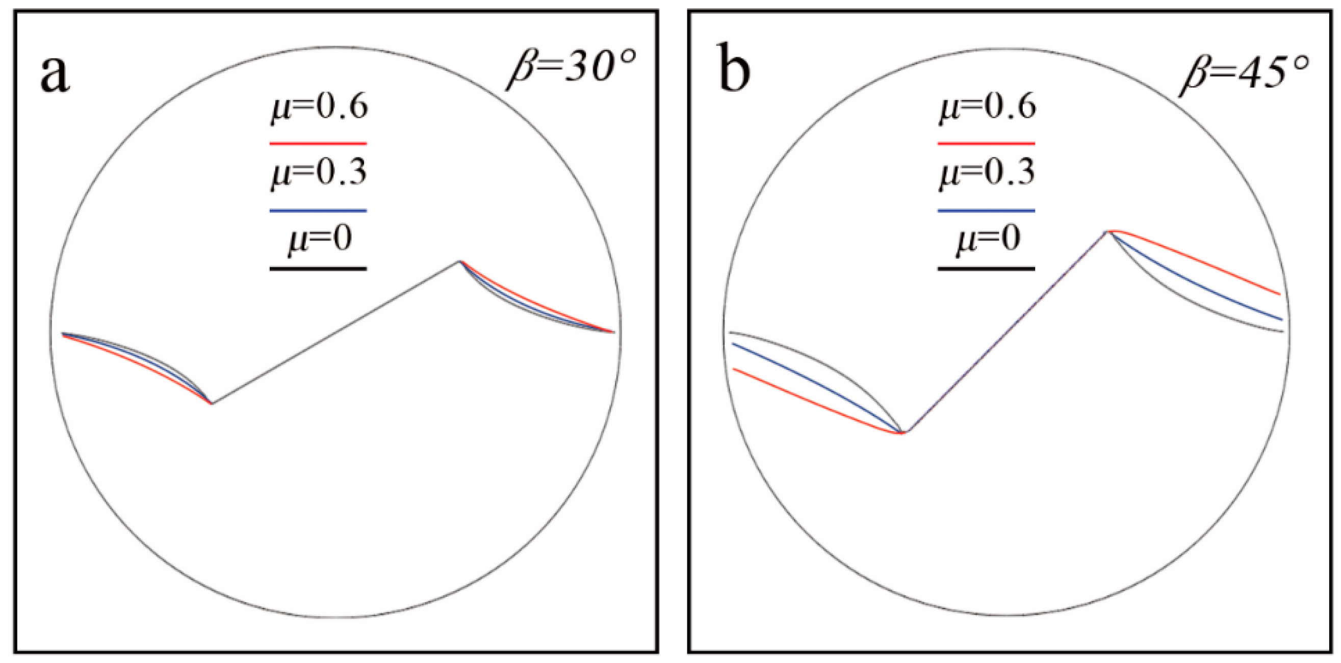
In this section, the dynamic effect would not be taken into account. First, this section compares the fracture trajectories obtained by MFEM and the experimental results [22], as shown in Figure 8. The strong consistency of the two growth paths confirms the effectiveness of the MFEM. Due to the satisfactory accuracy and versatility of the MFEM, proved by the previous results, the loading angle β takes the values of 30° and 45°for the sake of convenience. Except for the loading angle, the settings of other parameters are consistent with Section 4.2.2. Figure 9 and Figure 10 clearly illustrate the propagation trajectories, simulated by the MFEM, versus loading angle β with different friction coefficients (μ = 0, 0.3 and 0.6) and crack relative lengths (α = 0.3 and 0.5). From the results of the above figures, the friction has a certain effect on propagation of the crack. Meanwhile, in order to facilitate observation and comparison, crack propagation paths of the same crack length are overlapped.
It can be found that, in spite of the setting of the contact, when the friction coefficient is 0, the crack would eventually deviate from the original crack line and extend towards the loading direction. Under this condition, the increase of relative crack length and loading angle will increase the deviation of the crack, which could not change the type of crack. According to the previous research [8], it can be found that this kind of crack is a tensile wing crack. However, as the friction increases, the crack propagation is significantly affected.
Considering the symmetry of the CCBD, the propagation path extending from the right tip of the central crack is taken as the research object. In addition, the effects of different friction coefficients on growth trajectories of the crack are shown in the Figure 9 and Figure 10. The crack propagation path is greatly affected, which is manifested that the crack propagation path deviate upward. At the same time, as increasing the friction coefficient, the amount of the upward deviation increases and the curvature of the path decreases. In addition, there are some influences on crack type due to the change of friction coefficient. It can be found that when the loading angle β is equal to 30°, no matter what the friction coefficient is, the crack propagation path of the CCBD sample does not change significantly, which makes only the tensile wing crack occur. However, as β = 60°, tensile crack or mixed tensile-shear crack would begin to occur. For example, when β = 45° and μ = 0.3, the crack propagation path of the crack is like a straight line, without bending and extends in the direction of loading, which is called the tensile crack. Similarly, under the condition of this loading angle, mixed tensile-shear crack can be observed when μ = 0.6 and α = 0.5. According to the previous literature [50], when the values of α and β for the CCBD are small, the effect of friction is not obvious due to the incomplete contact of the crack surface. In addition, these conclusions can be embodied in the Figure 9 and Figure 10. Therefore, based on the above conclusions, the appropriate loading angle and relative crack length should be required, which makes the friction have a non-negligible effect on the crack surface.

5. Conclusions

The present work fits into the stream of study and analysis of the friction impact on fracture parameters (SIFs and T-stresses) and crack propagation of CCBD specimens under diametric forces. Considering the frictional contact, the MFEM is developed to investigate the above effects. In addition, the following conclusions can be drawn from the simulation results of several examples:
(1)
The friction has a significant effect on the mode II SIF after the crack is closed, but has no influence on the stress intensity factor of mode I and T-stress. When the crack is closed, the mode II SIF decreases obviously as increasing the friction.
(2)
There are significant effects on the crack propagation angle and crack propagation trajectory due to the change of the friction after the crack is closed with the appropriate relative crack length and loading angle.
(3)
When T-stress is positive, the influence of friction becomes obvious and the crack propagation angle increases with a lager friction coefficient.
(4)
After the crack is closed, as increasing the friction, the amount of the deviation increases and the curvature of the path decreases. Furthermore, the crack type is easier to change with the increase of friction.
(5)
The effects of friction on the mode II SIF and the propagation path are more obvious with the larger the relative crack length and loading angle.

Author Contributions

Conceptualization, J.H.; methodology, J.H.; validation, J.H., W.H. and S.D.; formal analysis, X.P. and J.L.; investigation, X.P. and J.L.; writing—original draft preparation, J.H.; writing—review and editing, S.D. and W.H. All authors have read and agreed to the published version of the manuscript.

Funding

This paper received no external funding.

Institutional Review Board Statement

Not applicable.

Informed Consent Statement

Not applicable.

Data Availability Statement

Not applicable.

Acknowledgments

The authors gratefully acknowledge the support from the National Natural Science Foundation of China (No. 11872042), the Sichuan Science and Technology Program (Nos. 2018JY0024, 2019YJ0156 and 2021YJ0357), the China Postdoctoral Science Foundation (2019M653395) and the Sichuan University Postdoctoral Research Foundation (2019SCU12049).

Conflicts of Interest

The authors declare no conflict of interest.

Nomenclature

Winteracting strain energy density
σ i j ( a c t ) , u i j ( a c t ) , ε i j ( a c t ) stresses, displacements and strains of the actual fields
σ i j ( a u x ) , u i j ( a u x ) , ε i j ( a u x ) stresses, displacements and strains of the auxiliary fields
Γ , C, C+, C-different integral contours
E*, Eelastic modulus
vPoisson’s ratio
K I ( a u x ) , K II ( a u x ) stress intensity factors of the auxiliary fields
K I , K II stress intensity factors of the actual fields
T T-stress
Pradial force
Bthickness of the CCBD
Rradius of the CCBD
ahalf the length of the crack
K I * , K II * , T * dimensionless forms of stress intensity factors and T-stress
fa line load
r , θ polar co-ordinates
βloading angle
θ0crack propagation angle

References

  1. Dong, S.; Wang, Y.; Xia, Y. Stress intensity factors for central cracked circular disk subjected to compression. Eng. Fract. Mech. 2004, 71, 1135–1148. [Google Scholar] [CrossRef]
  2. Markides, C.F.; Pazis, D.N.; Kourkoulis, S.K. Stress intensity factors for the Brazilian disc with a short central crack: Opening versus closing cracks. Appl. Math. Model. 2011, 35, 5636–5651. [Google Scholar] [CrossRef]
  3. Wu, B.; Yao, W.; Xia, K. An Experimental Study of Dynamic Tensile Failure of Rocks Subjected to Hydrostatic Confinement. Rock Mech. Rock Eng. 2016, 49. [Google Scholar] [CrossRef]
  4. Erarslan, N.; Williams, D.J. Mixed-Mode Fracturing of Rocks Under Static and Cyclic Loading. Rock Mech. Rock Eng. 2013. [Google Scholar] [CrossRef]
  5. Nemat-Nasser, S.; Horii, H. Compression-induced nonplanar crack extension with application to splitting, exfoliation, and rockburst. J. Geophys. Res. Solid Earth 1982, 87. [Google Scholar] [CrossRef]
  6. Cotterell, B. Brittle fracture in compression. Int. J. Fract. Mech. 1972, 8, 195–208. [Google Scholar] [CrossRef]
  7. Hoek, E.; Bieniawski, Z.T. Brittle fracture propagation in rock under compression. Int. J. Fract. 1965, 1, 137–155. [Google Scholar] [CrossRef]
  8. Wong, L.N.Y.; Einstein, H.H. Systematic evaluation of cracking behavior in specimens containing single flaws under uniaxial compression. Int. J. Rock Mech. Min. Sci. 2009, 46, 239–249. [Google Scholar] [CrossRef]
  9. Park, C.H.; Bobet, A. Crack initiation, propagation and coalescence from frictional flaws in uniaxial compression. Eng. Fract. Mech. 2010, 77, 2727–2748. [Google Scholar] [CrossRef]
  10. Basu, A.; Mishra, D.A.; Roychowdhury, K. Rock failure modes under uniaxial compression, Brazilian, and point load tests. Bull. Eng. Geol. Environ. 2013, 72, 457–475. [Google Scholar] [CrossRef]
  11. Hua, W.; Xu, J.; Dong, S.; Song, J.; Wang, Q. Effect of confining pressure on stress intensity factors for cracked Brazilian disk. Int. J. Appl. Mech. 2015, 7, 1550051. [Google Scholar] [CrossRef]
  12. Li, N.; Dong, S.; Hua, W. Analysis of the effect of crack face contact on stress intensity factors for a centrally cracked Brazilian disk. Rock Soil Mech. 2017, 38, 2395–2401. [Google Scholar] [CrossRef]
  13. Tang, S.B. Stress intensity factors for a Brazilian disc with a central crack subjected to compression. Int. J. Rock Mech. Min. Sci. 2017, 93, 38–45. [Google Scholar] [CrossRef]
  14. Hua, W.; Li, Y.; Dong, S.; Li, N.; Wang, Q. T-stress for a centrally cracked Brazilian disk under confining pressure. Eng. Fract. Mech. 2015, 149, 37–44. [Google Scholar] [CrossRef]
  15. Hua, W.; Li, J.; Huang, J.; Dong, S. Theoretical Error Analysis of the T-Stress for a Central Cracked Brazilian Disk Specimen. Int. J. Appl. Mech. 2020. [Google Scholar] [CrossRef]
  16. Tang, S.B. The effect of T-stress on the fracture of brittle rock under compression. Int. J. Rock Mech. Min. Sci. 2015, 79, 86–98. [Google Scholar] [CrossRef]
  17. Spagnoli, A.; Carpinteri, A.; Terzano, M. Mode II crack shielding in a compressed rough crack with friction. Theor. Appl. Fract. Mech. 2020, 107. [Google Scholar] [CrossRef]
  18. Zhou, X.; Wang, L.; Berto, F.; Zhou, L. Comprehensive study on the crack tip parameters of two types of disc specimens under combined confining pressure and diametric concentrated forces. Theor. Appl. Fract. Mech. 2019, 103, 102317. [Google Scholar] [CrossRef]
  19. Huang, J.; Li, J.; Pan, X.; Xie, T.; Hua, W.; Dong, S. Numerical Investigation on Mixed Mode (I-II) Fracture Propagation of CCBD Specimens Under Confining Pressure. Int. J. Appl. Mech. 2020, 12, 2050111. [Google Scholar] [CrossRef]
  20. Hou, C.; Wang, Z.; Liang, W.; Yu, H.; Wang, Z. Investigation of the effects of confining pressure on SIFs and T-stress for CCBD specimens using the XFEM and the interaction integral method. Eng. Fract. Mech. 2017, 178, 279–300. [Google Scholar] [CrossRef]
  21. Lim, I.L.; Johnston, I.W.; Choi, S.K. A finite element code for fracture propagation analysis within elasto-plastic continuum. Eng. Fract. Mech. 1996, 53, 193–211. [Google Scholar] [CrossRef]
  22. Haeri, H.; Shahriar, K.; Marji, M.F.; Moarefvand, P. Experimental and numerical study of crack propagation and coalescence in pre-cracked rock-like disks. Int. J. Rock Mech. Min. Sci. 2014, 67, 20–28. [Google Scholar] [CrossRef]
  23. Zhou, X.P.; Bi, J.; Qian, Q.H. Numerical Simulation of Crack Growth and Coalescence in Rock-Like Materials Containing Multiple Pre-existing Flaws. Rock Mech. Rock Eng. 2015, 48, 1097–1114. [Google Scholar] [CrossRef]
  24. Wang, Y.; Zhou, X.; Xu, X. Numerical simulation of propagation and coalescence of flaws in rock materials under compressive loads using the extended non-ordinary state-based peridynamics. Eng. Fract. Mech. 2016, 163, 248–273. [Google Scholar] [CrossRef]
  25. Wang, L.; Zhou, X. Phase field model for simulating the fracture behaviors of some disc-type specimens. Eng. Fract. Mech. 2020, 226, 106870. [Google Scholar] [CrossRef]
  26. Ty, B.; Black, T. Elastic Crack Growth in Finite Elements with Minimal Remeshing. Int. J. Numer. Method Eng. 1999, 45, 601–620. [Google Scholar] [CrossRef]
  27. Dolbow, J.; Moës, N.; Belytschko, T. An extended finite element method for modeling crack growth with frictional contact. Comput. Methods Appl. Mech. Eng. 2001, 190, 6825–6846. [Google Scholar] [CrossRef] [Green Version]
  28. Taniguchi, T. Crack propagation analysis in civil engineering structures. Comput. Struct. 1991, 41, 1295–1303. [Google Scholar] [CrossRef]
  29. Wang, Z.; Ma, L.; Yu, H.; Wu, L. Dynamic stress intensity factors for homogeneous and non-homogeneous materials using the interaction integral method. Eng. Fract. Mech. 2014, 128, 8–21. [Google Scholar] [CrossRef]
  30. Zhang, Y.; Guo, L.; Huang, K.; Bai, X.; Zhang, Z. A numerical method for the thermal-shock crack problems of nonhomogeneous materials with inclusions based on an interaction energy integral method. Eng. Fract. Mech. 2017, 190. [Google Scholar] [CrossRef]
  31. Kim, J.-H.; Paulino, G.H. T-stress, mixed-mode stress intensity factors, and crack initiation angles in functionally graded materials: A unified approach using the interaction integral method. Comput. Methods Appl. Mech. Eng. 2003, 192, 1463–1494. [Google Scholar] [CrossRef]
  32. Yu, H.; Wu, L.; Guo, L.; Li, H.; Du, S. T-stress evaluations for nonhomogeneous materials using an interaction integral method. Int. J. Numer. Method Eng. 2012, 90, 1393–1413. [Google Scholar] [CrossRef]
  33. Williams, M.L. On the Stress Distribution at the Base of a Stationary Crack. J. Appl. Mech. 1957, 24, 109–114. [Google Scholar] [CrossRef]
  34. Yu, H.; Wang, J.; Shimada, T.; Wu, H.; Wu, L.; Kuna, M.; Kitamura, T. An I-integral method for crack-tip intensity factor variation due to domain switching in ferroelectric single-crystals. J. Mech. Phys. Solids 2016. [Google Scholar] [CrossRef]
  35. Erdogan, F.; Sih, G. On the Crack Extension in Plates Under Plane Loading and Transverse Shear. J. Basic Eng. 1963, 85. [Google Scholar] [CrossRef]
  36. Lin, Q.; Wang, S.; Pan, P.Z.; Ji, W.W.; Lu, Y. Fracture initiation under pure shear revisited: Remarks on the mode II fracture in quasi-brittle materials. Theor. Appl. Fract. Mech. 2020. [Google Scholar] [CrossRef]
  37. Sih, G.C. Strain-energy-density factor applied to mixed mode crack problems. Int. J. Fract. 1974, 10, 305–321. [Google Scholar] [CrossRef]
  38. Hussain, M.A.; Pu, S.L.; Underwood, J. Strain Energy Release Rate for a Crack Under Combined Mode I and Mode II. Irwin, G.R., Ed.; ASTM International: West Conshohocken, PA, USA, 1974; Volume 28, pp. 2–28. [Google Scholar] [CrossRef]
  39. Ayatollahi, M.R.; Aliha, M.R.M.; Hassani, M.M. Mixed mode brittle fracture in PMMA—An experimental study using SCB specimens. Mater. Sci. Eng. A 2006, 417, 348–356. [Google Scholar] [CrossRef]
  40. Akbardoost, J.; Ayatollahi, M.R. Experimental analysis of mixed mode crack propagation in brittle rocks: The effect of non-singular terms. Eng. Fract. Mech. 2014, 129, 77–89. [Google Scholar] [CrossRef]
  41. Hua, W.; Dong, S.; Xu, J. Experimental study on the fracture toughness of rust stone under mixed mode loading condition. Mater. Res. Innov. 2015, 19, 531–536. [Google Scholar] [CrossRef]
  42. Ayatollahi, M.R.; Aliha, M.R.M. Mixed mode fracture analysis of polycrystalline graphite–A modified MTS criterion. Carbon 2008, 46, 1302–1308. [Google Scholar] [CrossRef]
  43. Fett, T. T -stresses in rectangular plates and circular disks. Eng. Fract. Mech. 1998, 60, 631–652. [Google Scholar] [CrossRef]
  44. Fett, T. Stress intensity factors and T-stress for internally cracked circular disk under various boundary conditions. Eng. Fract. Mech. 2001, 68, 1119–1136. [Google Scholar] [CrossRef]
  45. Atkinson, C.; Smelser, R.E.; Sanchez, J. Combined mode fracture via the cracked Brazilian disk test. Int. J. Fract. 1982, 18, 279–291. [Google Scholar] [CrossRef]
  46. Jaeger, J.C.; Cook, N.G.W.; ZImmerman, R.W. Fundamentals of Rock Mechanics, 4th ed.; Wiley-Blackwell: Oxford, UK, 2007. [Google Scholar]
  47. Shephard, M.S.; Yehia, N.A.B.; Burd, G.S.; Weidner, T.J. Automatic crack propagation tracking. Comput. Struct. 1985, 20, 211–223. [Google Scholar] [CrossRef]
  48. Mardon, D.; Kronenberg, A.K.; Handin, J.; Friedman, M.; Russell, J.E. Mechanisms of fracture propagation in experimentally extended Sioux quartzite. Tectonophysics 1990, 182, 259–278. [Google Scholar] [CrossRef]
  49. Basista, M.; Gross, D. A Note on Crack Interactions Under Compression. Int. J. Fract. 2000, 102, 67–72. [Google Scholar] [CrossRef]
  50. Dorogoy, A.; Banks-Sills, L. Effect of crack face contact and friction on Brazilian disk specimens—A finite difference solution. Eng. Fract. Mech. 2005, 72, 2758–2773. [Google Scholar] [CrossRef]
  51. Xie, Y.J.; Duo, Y.L.; Yuan, H. Potential fracture paths for cracked rocks under compressive-shear loading. Int. J. Rock Mech. Min. Sci. 2020, 128, 104216. [Google Scholar] [CrossRef]
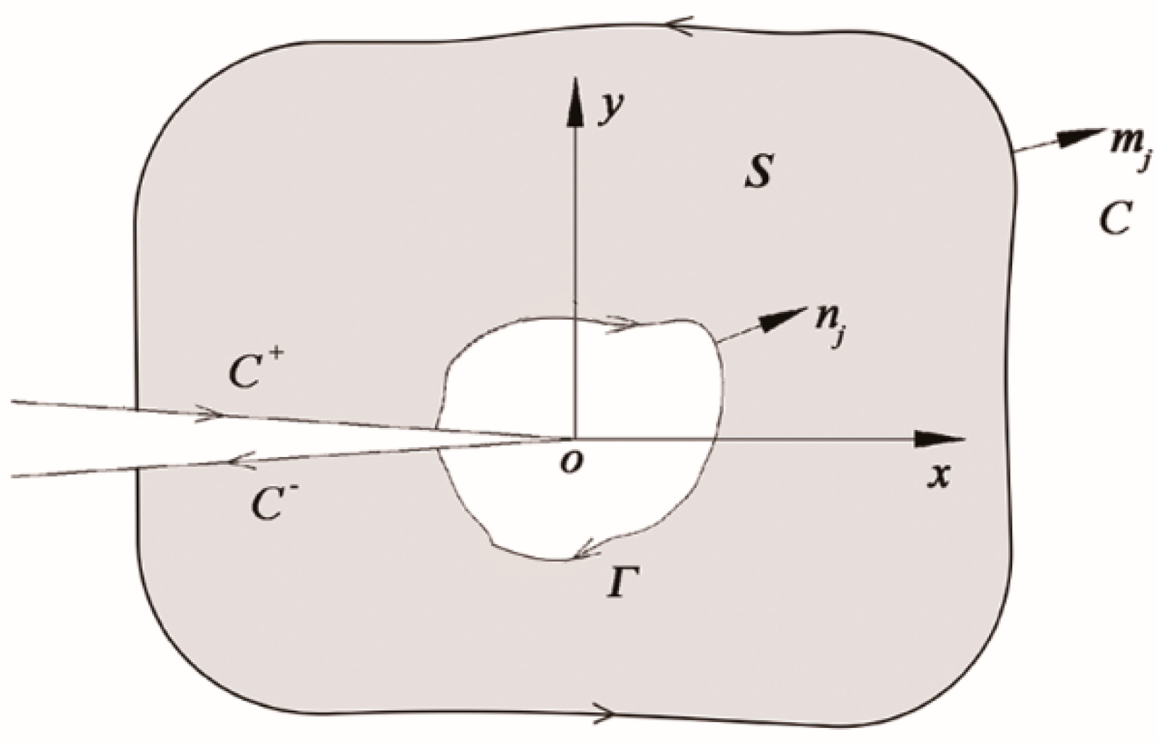
Figure 1. The equivalent surface integral of the interaction integral.
Applsci 11 02839 g001
Figure 2. Schematic of the coordinate system for the crack tip.
Applsci 11 02839 g002
Figure 3. Schematic of the crack propagation angle and loading angle.
Applsci 11 02839 g003
Figure 4. Process of the simulation [19].
Applsci 11 02839 g004
Figure 5. Numerical model of a central crack Brazilian disc.
Applsci 11 02839 g005
Figure 6. The normalized SIFs and T-stresses for various friction coefficients. (a) μ = 0, (b) 0.2, (c) 0.4, (d) 0.6, (e) 0.8.
Applsci 11 02839 g006
Figure 7. The crack propagation angle θ0 versus the loading angle β with different relative crack lengths α. (a) α = 0.3, (b) α = 0.5.
Applsci 11 02839 g007
Figure 8. Comparison of simulation results and experimental results for crack paths in CCBD specimens for α = 0.3. (a) β = 0°, (b) 15°, (c) 30°, (d) 45°, (e) 60°.
Applsci 11 02839 g008
Figure 9. The propagation trajectories simulated by the MFEM under different friction coefficients for α = 0.3.
Applsci 11 02839 g009
Figure 10. The propagation trajectories simulated by the MFEM under different friction coefficients for α = 0.5.
Applsci 11 02839 g010
Table 1. CCBD model parameters for simulation.
CategoriesValues
Geometry charactersR (mm)50
B (mm)30
Material propertiesCompressive strength σc (MPa)28
Tensile strength σt (MPa)3.81
Poisson’s ratio v0.21
Young’s modulus E (GPa)15
Publisher’s Note: MDPI stays neutral with regard to jurisdictional claims in published maps and institutional affiliations.