Article

Shape Optimization of an Integrated Mast for RCS Reduction of a Stealth Naval Vessel

1
Department of AI Convergence Network, Ajou University, Suwon 16499, Korea
2
Hanwha Systems, Yongin 17121, Korea
3
Department of Electrical and Computer Engineering, Sungkyunkwan University, Suwon 16419, Korea
4
Department of Electrical and Computer Engineering, Ajou University, Suwon 16499, Korea
*
Author to whom correspondence should be addressed.
Appl. Sci. 2021, 11(6), 2819; https://doi.org/10.3390/app11062819
Submission received: 16 February 2021 / Revised: 15 March 2021 / Accepted: 19 March 2021 / Published: 22 March 2021

Abstract

:
In this paper, we analyze the radar cross section (RCS) of an integrated mast and present the optimized mast shape for RCS reduction. The RCS is simulated using commercial electromagnetic (EM) software based on the shooting and bouncing rays (SBR) method and the diffraction fields at the edges are also considered. Threat frequencies, threat regions and cardinal points are first defined considering the operational environments of a naval vessel. We calculate and analyze the RCS of the integrated mast in terms of the threat frequencies, the shapes of the integrated mast and the direction and polarization of the incident waves. The shape of the integrated mast is optimized based on the shaping technique. The optimized mast has low RCS properties in the primary threat sectors except for the exceptional angle regions.

1. Introduction

The rapid development of radar technology has made it possible to detect the presence of enemy vessels early but it has become difficult to operate or hide without notifying the enemy of the presence of friendly naval ships. In other words, the survivability of friendly naval ships has also been threatened [1]. Thus, it is essential to apply low observable technologies to naval ships to avoid detection by enemy radar. Due to the fact that the smaller a radar cross section is (RCS), the better the naval ships can evade radar detection, RCS reduction is a very important factor in stealth technology [1,2]. Electromagnetic (EM) stealth technology focuses on reducing the RCS and it has become a vital design goal of tactical naval vessels [2,3,4]. The Zumwalt destroyer, a state-of-the-art United States Navy destroyer, is designed to have a remarkably low RCS. Although the Zumwalt destroyer is much larger than any other active destroyer or cruiser such as an Arleigh Burke-class destroyer its RCS is similar to a fishing boat. For this extreme stealth-oriented design, an integrated mast module system must be developed [5]. The dozens of radars, sensors and antennas installed on conventional naval vessels severely increase the RCS of naval vessels due to the influence of multiple reflections whereas the integrated mast consists of a housing that accommodates all major radars, sensors and antennas of naval vessels, which can dramatically reduce the RCS of naval vessels. As enemy radars in distant areas may only detect the integrated mast due to the curvature of the earth, the RCS of the naval ship and also the RCS of the integrated mast itself are very important in the stealth ship. Therefore, it is necessary to design the integrated mast with low observable characteristics.
The most practical techniques for designing the integrated mast with a low RCS include shaping techniques and radar absorbing materials (RAM)/radar absorbing structures (RAS). Extensive studies have been conducted to develop RAM/RAS for RCS reduction [6,7,8,9,10,11,12,13,14,15,16,17]. Composite radar absorbers have been fabricated and measured based on the composite material [6,7,8], the metasurface [9,10] and the reactive Salisbury screen [11]. Furthermore, the RCS of naval ships covered with RAM was numerically analyzed to evaluate its stealth performance [12,13,14,15,16] and the RCS of an integrated mast coated with multi-layered RAM was also analyzed [17]. However, they usually have a narrow absorption bandwidth and are too bulky and fragile in operational environments, which incurs astronomical costs for its ongoing maintenance. Furthermore, the surface of the integrated mast that can be coated with RAM/RAS is very limited due to the dozens of radars, sensors and antennas installed on the integrated mast. Therefore, RAM/RAS techniques are rarely applied to operational naval ships. On the other hand, shaping techniques must be used in stealth design because it is the most effective technique that can be used to reduce the RCS [2]. Shaping techniques are generally first used to have low RCS properties in the primary threat sectors before RAM/RAS techniques are applied. As the shape of the integrated mast is one of the most important factors and must be considered in the early stages of the concept/design, it is necessary to know in advance the characteristics of the RCS of the integrated mast and the naval vessel equipped with the integrated mast. To investigate the RCS characteristics of naval vessels, there have been many studies [13,18,19,20,21,22]. The RCS of naval vessels has been investigated [18,19] and its properties have been analyzed according to the side slope of the superstructure [13] and exterior equipment arrangement such as the sensor and radar [20]. However, related studies on the RCS of the integrated mast itself seem to be lacking. Although the previous studies were conducted to analyze the RCS of the integrated mast [21] and the simplified battleship equipped with the integrated mast [22] an investigation on the optimization of the integrated mast shape for RCS reduction has not been presented. Therefore, it is of great significance to optimize the mast shape for RCS reduction and to analyze the RCS of the naval ship equipped with the optimized mast.
In this paper, we analyze the RCS of an integrated mast and present the optimized mast shape for RCS reduction. To avoid the unnecessary RCS spikes in the RCS pattern of the naval ship equipped with the integrated mast and to minimize the multiple reflections caused by the interaction with the mast and the naval ship we optimize the integrated mast considering the shape of the naval vessel. The stealth performance of the optimized mast is checked through the analysis of the RCS of a naval ship equipped with an integrated mast. The RCS is simulated using commercial electromagnetic (EM) software based on the shooting and bouncing rays (SBR) method and the diffraction fields at the edges are also considered. First of all, we define the threat frequency and the threat region by considering the operational environments of the naval vessel such as the shape of the ship and the radar signals coming from the enemy radar. We then simulate and analyze the RCS of the integrated mast in terms of the threat frequency, the integrated mast shape and the direction and polarization of the incident waves. The integrated mast shape is optimized in the consideration of the defined threat region. As the RCS reduction cannot be done for all incident angles in the spherical coordinate system, cardinal points are defined as exceptional angle ranges. The integrated mast is designed to have low RCS properties in the primary threat sectors except for the exceptional angle regions and the improvement of the RCS of the naval ship equipped with the optimized mast is confirmed.

2. Analysis Procedure

The SBR method is a well-known high frequency approximation technique that is efficiently capable of predicting the RCS of large objects such as naval ships based on the determination of the equivalent current densities induced on the surface of an illuminated perfect electric conductor (PEC) plane [23,24,25]. In this study, The RCS was simulated using commercial electromagnetic (EM) software based on the SBR method and the diffraction fields at the edges were also considered.
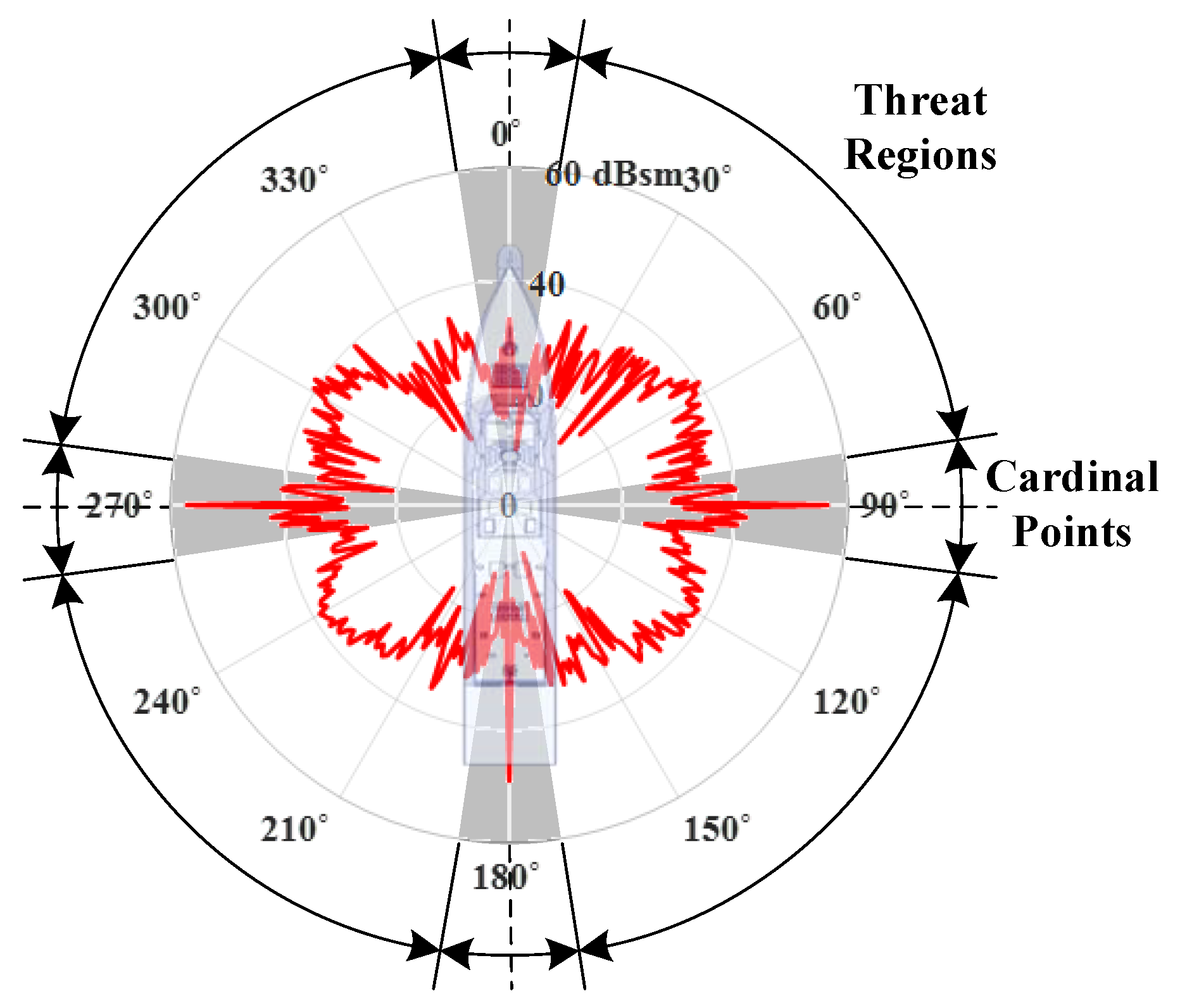
The integrated mast can dramatically reduce the RCS of a naval vessel. In the stealth design of a naval vessel, not only the RCS of the naval ship but also the RCS of the integrated mast itself is very important. This is because enemy radars in distant areas may only detect the integrated mast located on top of the naval ship due to the curvature of the earth. Therefore, it is essential to design the integrated mast with low RCS characteristics in the stealth design of a naval vessel. The goals of shaping are to have specular reflections of the EM field in a direction away from the enemy radar and this technique is the most representative and effective technique that can be used to reduce the RCS [2]. The shaping technique is usually used first to design the shape of the integrated mast with low RCS properties before other techniques such as RAM/RAS are applied. In other words, the shape of the integrated mast is one of the most important factors in the stealth design of a naval ship and must be considered in the early stages of the concept/design. Figure 1 shows an overall procedure to design the integrated mast shape. As the integrated mast mounted on a naval ship must have stable structural characteristics, the base width and length are determined by the superstructure of the naval ship. In addition, the ranges of the size and slope of the surface of the integrated mast are determined by the size, performance and installation concept of the many antennas and sensors to be installed on the surface of the integrated mast. In other words, the basic size and shape of the integrated mast are set by the naval ship and the antennas and sensors and the ranges of the size and shape that can be redesigned are constrained. Therefore, the shape of the integrated mast is optimized within these constraints by the iterative redesign. First of all, the cardinal points, which are the exceptional angle regions and the expected threats such as the frequencies, polarizations and detection ranges of enemy radars, are defined for operational requirements. In a naval ship, the main concerns are generally radar signals coming from distant patrol aircraft, other ships and sea-skimming anti-ship missiles with radar seekers usually near or slightly above the horizon as seen from the ship. In other words, the threat regions are usually 0° to 360° in the azimuth plane and very limited in the elevation plane. The RCS of the integrated mast should be reduced in all azimuth planes due to the defined threat regions but RCS reduction cannot be achieved for all incident angles in the spherical coordinate system. As mentioned above, this is because shaping is limited because of the dozens of radars, sensors and antennas installed on the integrated mast. Therefore, a definition of the cardinal points that are exceptional angle ranges are also needed with considerations for the operational environments of the naval vessel such as the shape of the ship and the radar signals coming from the enemy radar. Figure 2 shows an example of the cardinal points of a naval ship. As shown in Figure 2, the cardinal points for the naval ship in the azimuth plane are generally in the regions of the bow, the starboard, the port and the stern. After that, the RCS of an initial model of the integrated mast is calculated and analyzed. In order to evaluate the RCS of the integrated mast, the RCS pattern and the representative RCS values such as the geometric mean and the arithmetic mean [3,4,21,22] are used. The geometric mean and the arithmetic mean are given as follows, respectively.
Geometric   mean = 1 N ( 10 log 10 σ 1 + 10 log 10 σ 2 + + 10 log 10 σ N )   dBsm .
Arithmetic   mean = 10 log 10 ( 1 N k = 1 N σ k )   dBsm .
The representative RCS value is one of the most important stealth parameters because it is used to determine the probability of survivability. As evaluation results may differ depending on the type of the representative RCS value, at least two representative values should be used and the performance should be evaluated comprehensively. Whether the goal is achieved or not should then be checked and an analysis on the major causes of the RCS increase based on the ray path and the RCS hotspot should be performed. The parts of the integrated mast that should be optimized are defined and they are redesigned using the shaping technique. The integrated mast is redesigned with low RCS properties in the primary threat sectors except for the cardinal points. The RCS reduction is basically achieved by adjusting the side slope of the integrated mast. Corner reflectors such as dihedrals, trihedrals and cavities should be absolutely avoided in a low RCS design as they extremely increase the RCS because of the influence of multiple reflections. In particular, for a naval ship equipped with an integrated mast, unnecessary RCS spikes can be generated by the integrated mast and the RCS can be increased due to the multiple reflections caused by the interaction of the mast and the ship. The side slope of the integrated mast is designed with the same slope of the superstructure of the naval ship to avoid unnecessary RCS spikes. In order to minimize the multiple reflections caused by the corner reflectors formed by the integrated mast and the superstructure or deck, the intersecting surfaces of the corner reflectors should be designed with acute or obtuse angles. It is also necessary to reduce the RCS by removing or minimizing the round shape of the integrated mast such as cylindrical and spherical structures and truncated cones. Finally, the integrated mast is iteratively redesigned to obtain an even better shape. The optimized mast should be designed to focus the reflected EM fields on the cardinal points and it should be in harmony with the naval vessel itself so that the RCS pattern of the naval vessel is not changed by the integrated mast.

3. Analysis Results

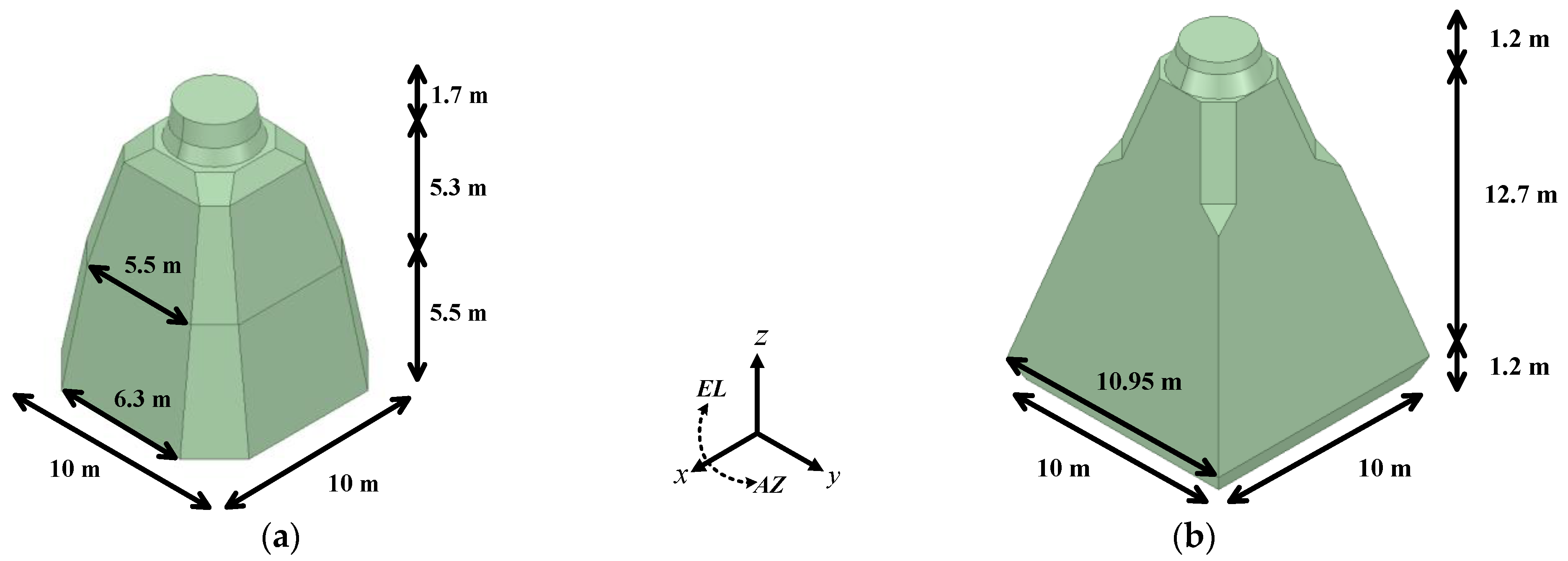
According to the aforementioned rules in Section 2, we defined the threat frequencies of the L-, S- and X-band and the threat regions of 0° to 360° in the azimuth plane and 0° to 10° in the elevation plane, respectively. The cardinal points were also defined as ±5° in the forward, starboard, port and stern regions in the azimuth plane. Figure 3 shows the geometry and dimension of the initial shape and optimized shape of the integrated mast, respectively. The length, width and height of the initial integrated mast were 10 m, 10 m and 12.5 m, respectively, and those of the optimized mast were 10.95 m, 10.95 m and 15.1 m, respectively. The details of the dimensions of the initial and optimized design are shown in Figure 3. The physical size of the optimized mast was a little larger than the initial integrated mast. We analyzed the RCS of the integrated mast using the asymptotic solver of CST Microwave Studio based on the SBR method, which included the diffraction fields at the edges [26]. We assumed that the integrated mast and the naval vessel were a PEC. The maximum number of reflections was set to five and the mesh consisted of curved triangles and the normal tolerance/degree was set to five. The simulation was carried out on a PC (Dual Intel Xeon CPU E5-2640 v4 at 2.40 GHz, 256 GB memory).
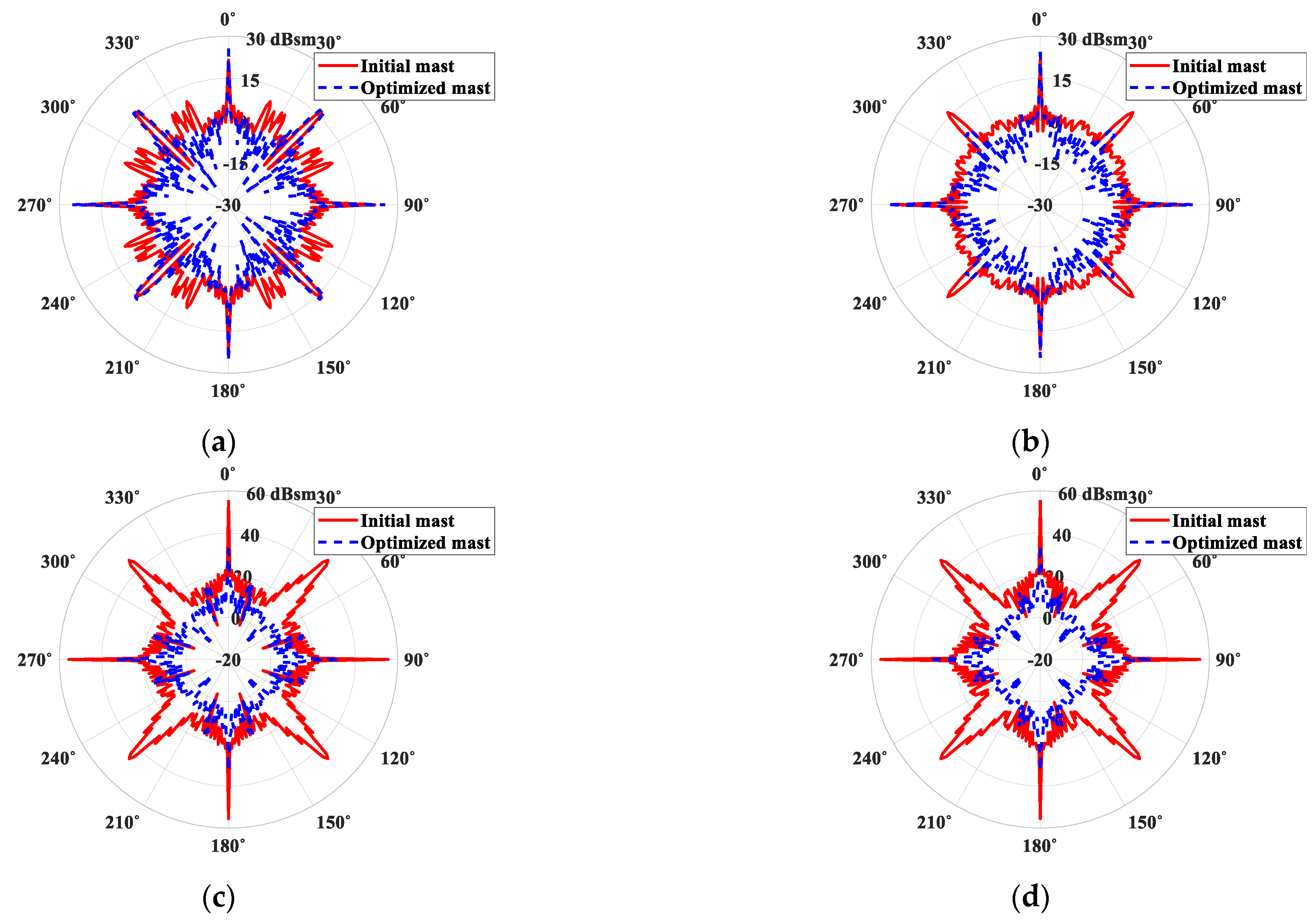
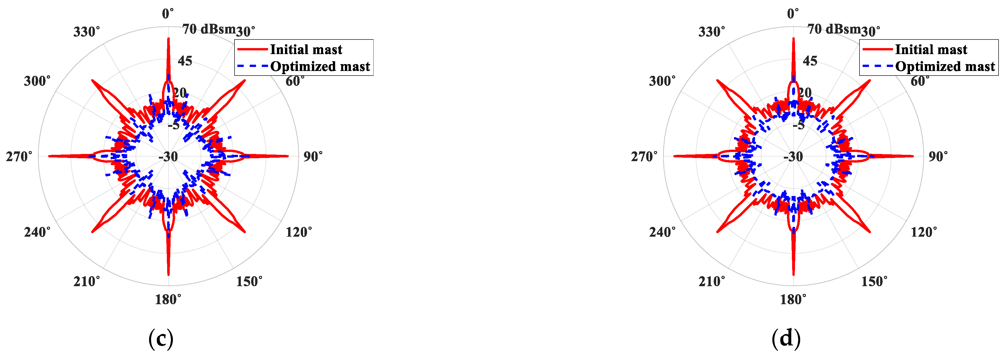
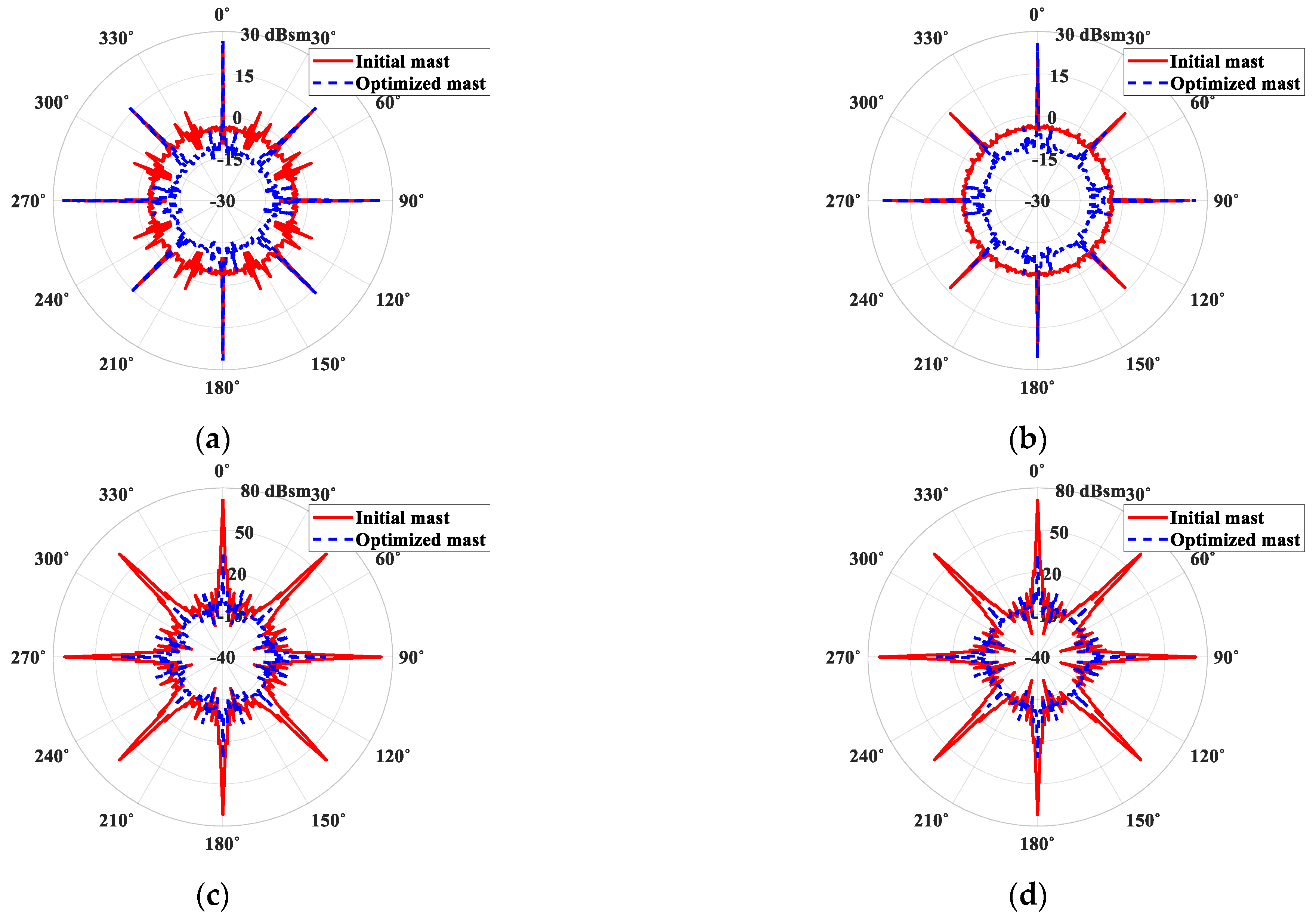
The RCS was simulated in the azimuth plane and in the elevation plane at intervals of 1° in the L-, S- and X-band, respectively. The RCS results of the initial model and the optimized mast are illustrated in Figure 4 and Figure 5 as three-dimensional RCS patterns, respectively. The scattering mechanism was mainly composed of specular reflections and edge diffractions. As shown in Figure 4, the RCS of the initial model had many spikes regardless of frequencies and polarizations. The major spikes of the initial model occurred at 0°, 45°, 90°, 135°, 180°, 225°, 270° and 315° in the azimuth plane for the elevation angles of 10° and 15° due to the side slope and the chamfered edges. However, as the spikes at 0°, 45°, 90°, 135°, 180°, 225°, 270° and 315° in the azimuth plane when the elevation angle was at 10° were in the threat regions, they had to be eliminated or minimized for stealth design. To eliminate or minimize the spikes, we reduced the chamfered edges at 45°, 135°, 225° and 315° in the azimuth plane and left only a minimum space for antenna installations. The side slope of the integrated mast was redesigned with the same slope as the superstructure to focus the spikes on the cardinal point. Moreover, the top radius and the height of the truncated cone were modified to reduce the RCS. The shape of the integrated mast was minutely changed in all parts and the overall size of the integrated mast was slightly increased. As shown in Figure 5, the RCS of the optimized model had four or eight major spikes in the azimuth plane when the elevation angle was at 15° regardless of frequencies and polarizations but the spikes were not in the threat regions. To compare both the results of the initial and the optimized shape, their RCS patterns in the azimuth plane for the elevation angles of 0° and 10° in the L-, S- and X-band were plotted and are shown in Figure 6, Figure 7 and Figure 8, respectively. Note the results at the elevation angle of 0° in the L-, S- and X-band. Due to the impact of the scattering by the truncated cone on the top of the integrated mast, both the results for the initial mast and the optimized mast had four spikes in the threat regions, which were at around 45°, 135°, 225° and 315°, but they had relatively uniform values in the rest of the regions. Furthermore, the RCS (red and solid line) of the initial integrated mast was larger than that (blue and dashed line) of the optimized mast in the threat regions. At an elevation angle of 10°, the RCS patterns of the initial integrated mast were also generally larger than those of the optimized mast and also had four spikes in the threat regions among the eight major spikes. On the other hand, the RCS spikes of the optimized mast were removed or minimized in the threat regions. In order to obtain the representative RCS values of the integrated mast, the geometric mean and the arithmetic mean were used. The geometric mean and the arithmetic mean were calculated based on all azimuth angles except for the cardinal points in a particular elevation angle and are listed in terms of the elevation angle in Table 1 and Table 2, respectively. The geometric mean and the arithmetic mean of the optimized mast decreased by a maximum of 25.39 dBsm and 46.46 dBsm and by an average of 12.63 dBsm and 14.57 dBsm, respectively, compared with those of the initial mast. The representative RCS values of the optimized mast were improved overall. However, the geometric mean for the VV polarization at an elevation angle of 3° in the X-band and the arithmetic mean for HH polarization at an elevation angle of 0° in the S-band were degraded by 1.66 dBsm and 2.1 dBsm, respectively. It may seem that there were a few problems with the optimized mast but there were not. This was because, as mentioned in Section 2, the shape was limited due to the dozens of radars, sensors and antennas installed on the integrated mast, which might make it impossible to reduce the RCS for all incident angles in the spherical coordinate system. The geometric mean and the arithmetic mean also might have different results because the geometric mean had the dominant value for the large values and the arithmetic mean had the dominant value for the small values. Note the results in Figure 7a. The RCS (solid line) of the initial integrated mast had mostly larger values than those (dashed line) of the optimized mast but smaller values at azimuth angles of 45°, 135°, 225° and 315°. Therefore, the arithmetic mean of the optimized mast was larger than that of the initial mast due to the RCS values at the elevation angles of 45°, 135°, 225° and 315°. This was why the geometric mean and the arithmetic mean had different results as shown in Figure 7a.
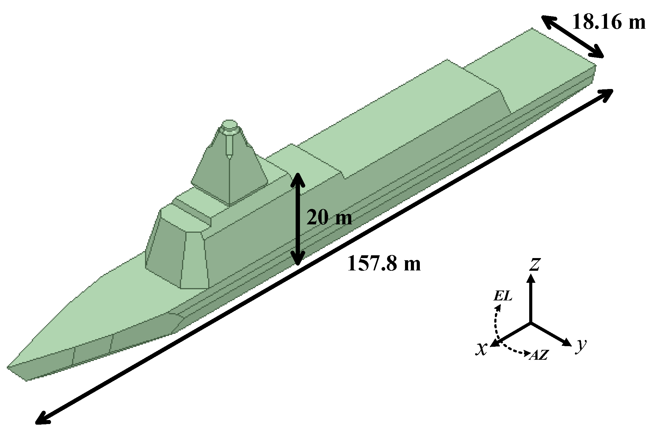
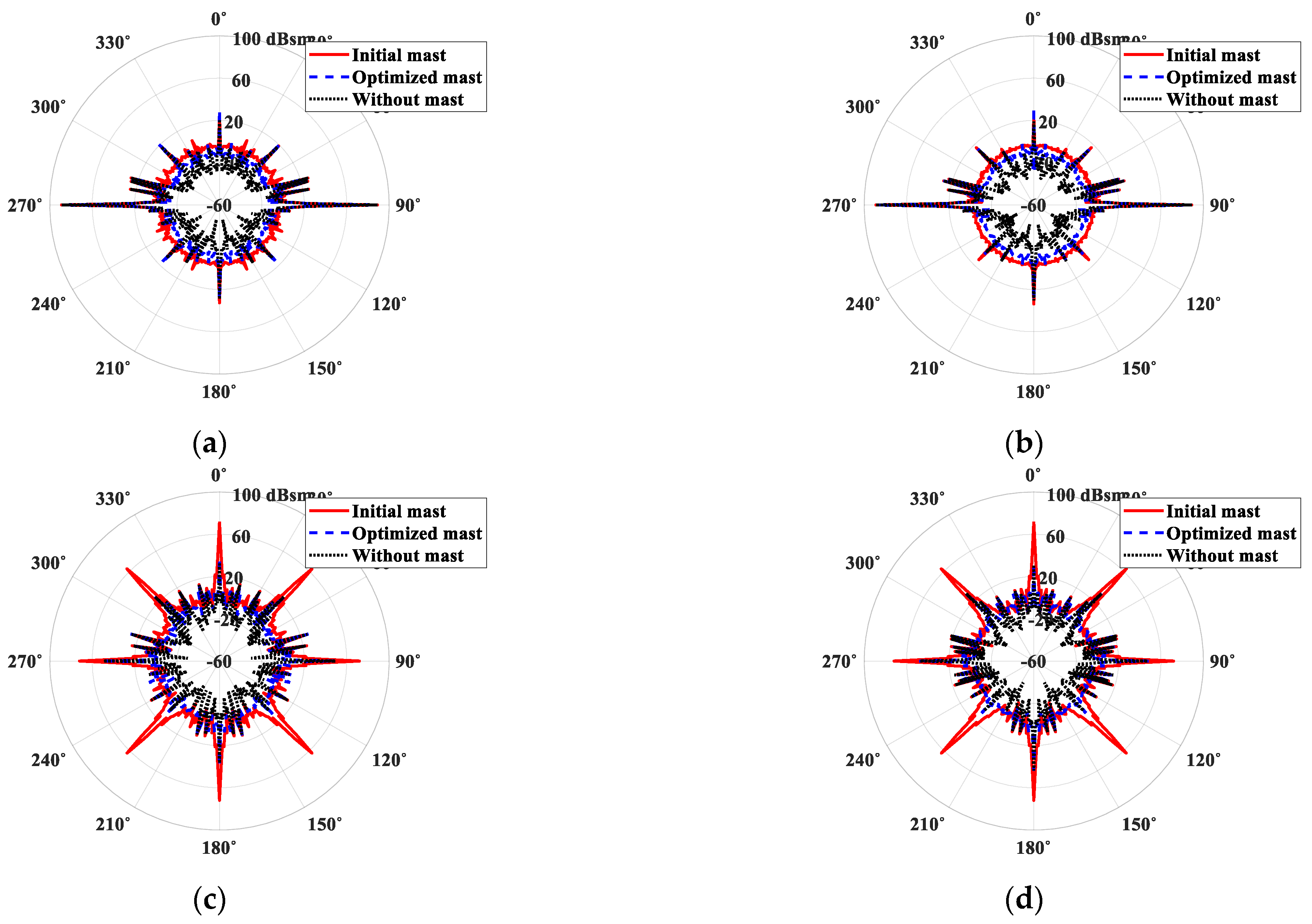
The RCS of a naval vessel equipped with each mast was also analyzed to evaluate its stealth performance. Figure 9 shows the geometry and dimension of the naval vessel used in the simulation. The length, width and height of the naval vessel were 152.1 m, 18.14 m and 24.9 m, respectively. The RCS patterns (red and solid line) of the naval vessel equipped with the initial mast in the azimuth plane for the elevation angles of 0° and 10° in the L-, S- and X-band were plotted and are shown in Figure 10, Figure 11 and Figure 12, respectively. The results with the optimized mast (blue and dashed line) and without the mast (black and dotted line) were also plotted and can be seen in the same Figures, respectively. The naval ship generally had large RCS values in the regions of the bow, the starboard, the port and the stern. The physical size of the naval ship was very large but the RCS of the naval ship itself was relatively very small due to the superstructure and the hull form, which had sloping sides. Although the integrated mast was mounted on the naval ship, the RCS results with and without the mast were very similar as seen in Figure 9a and Figure 10b. However, the RCS was seen to be larger in the order of no mast, optimization mast and initial mast. Additionally, the RCS pattern for the initial mast was found to have four additional spikes in the threat regions at an elevation angle of 10° (see Figure 10c,d, Figure 11c,d and Figure 12c,d). From these results, it could be seen that the scattered field was mainly composed of the influence by the integrated mast with a relatively small physical size rather than the naval ship. In the same manner as the representative RCS value of the integrated masts, the geometric mean and the arithmetic mean of the naval ship equipped with each mast were calculated and are listed in Table 3 and Table 4, respectively. The geometric mean and the arithmetic mean of the optimized mast decreased by a maximum of 24.05 dBsm and 34.83 dBsm and by an average of 10.42 dBsm and 9.97 dBsm, respectively, compared with those of the initial mast. As for the result of the integrated mast itself, there were a couple of cases where the representative RCS values of the optimized mast were larger than those of the initial mast but it could be seen that the RCS values of the optimized mast improved overall. From these results, it could be seen that the optimized mast had low RCS properties and minimally affected the RCS patterns of the naval vessel. As the geometric mean and arithmetic mean also might have had different results, we confirmed that the RCS characteristics should be evaluated comprehensively.

4. Conclusions

We analyzed the RCS of an integrated mast and presented the optimized integrated mast shape for RCS reduction. We also checked the stealth performance of the optimized integrated mast shape though the computation of the RCS of a naval ship equipped with the integrated mast. The RCS of the integrated mast was investigated in terms of the threat frequency, the integrated mast shape and the direction and polarization of the incident waves. The optimization of the integrated mast was conducted for RCS reduction based on the shaping technique. The integrated mast was designed to have low RCS properties in the primary threat sectors except for the exceptional angle regions. The geometric mean and the arithmetic mean of the optimized mast were reduced by a maximum of 25.39 dBsm and 46.46 dBsm and by an average of 12.63 dBsm and 14.57 dBsm, respectively, compared with those of the initial mast. We also analyzed the RCS of a naval vessel equipped with the integrated mast and confirmed the improvement of the RCS. The geometric mean and the arithmetic mean of a naval ship equipped with the optimized mast were improved by a maximum of 24.05 dBsm and 34.83 dBsm and by an average of 10.42 dBsm and 9.97 dBsm, respectively, compared with the case of the initial mast. We confirmed that the optimized mast had relatively small RCS values in the threat regions except for the cardinal points and minimally affected the RCS patterns of the naval vessel. These results can be used to develop an integrated mast for stealth vessels.

Author Contributions

The present work was conducted in cooperation with all authors. H.S. analyzed the problem and performed numerous simulations; H.S., D.Y., C.K., Y.S.Y., M.G.L., J.Y.P., K.C.H. and Y.B.P. contributed to the conceptualization, investigation and review; H.S. wrote a draft that was edited by all co-authors. All authors have read and agreed to the published version of the manuscript.

Funding

This research received no external funding.

Institutional Review Board Statement

Not applicable.

Informed Consent Statement

Not applicable.

Data Availability Statement

Not applicable.

Acknowledgments

This research was partly supported by Hanwha systems, the Basic Science Research Program through the National Research Foundation of Korea (NRF) funded by the Ministry of Science and ICT (No. 2020R1A2B5B01002251), and the MSIT(Ministry of Science and ICT), Korea, under the ITRC(Information Technology Research Center) support program(IITP-2021-2018-0-01424) supervised by the IITP(Institute for Information & communications Technology Promotion).

Conflicts of Interest

The authors declare no conflict of interest.

References

  1. Lees, P.A.; Davies, M.R. Computer prediction of RCS for military targets. IEE Proc. F (Radar Signal Process.) 1990, 137, 229–236. [Google Scholar] [CrossRef] [Green Version]
  2. Knott, E.F.; Shaeffer, J.F.; Tuley, M.T. Radar Cross Section, 2nd ed.; SciTech Publishing: Edison, NJ, USA, 2004; pp. 269–356. ISBN 1-891121-25-1. [Google Scholar]
  3. Ahn, B.-J. A study on the recent analysis method for the RCS reduction for naval ships. J. Korean Inst. Electromagn. Eng. Sci. 2014, 25, 333–338. [Google Scholar] [CrossRef]
  4. Ahn, B.-J.; Seo, S. A study on the setting procedure of standard value and design target value for the RCS reduced design for naval ships. J. Korean Inst. Electromagn. Eng. Sci. 2015, 26, 581–588. [Google Scholar]
  5. Seo, H.P.; Lee, K.H. Integrated mast applied for improving stealth ship performance. J. Korean Assoc. Def. Ind. Stud. 2015, 22, 27–46. [Google Scholar]
  6. Oh, J.-H.; Oh, K.-S.; Kim, C.-G.; Hong, C.-S. Design of radar absorbing structures using glass/epoxy composite containing carbon black in X-band frequency ranges. Compos. B. Eng. 2004, 35, 49–56. [Google Scholar] [CrossRef]
  7. Chin, W.S.; Lee, D.G. Development of the composite RAS (radar absorbing structure) for the X-band frequency range. Compos. Struct. 2007, 77, 457–465. [Google Scholar] [CrossRef]
  8. Choi, W.-H.; Song, W.-H.; Lee, W.-J. Broadband radar absorbing structures with a practical approach from design to fabrication. J. Electromagn. Eng. Sci. 2020, 20, 254–261. [Google Scholar] [CrossRef]
  9. Lee, I.G.; Yoon, S.H.; Lee, J.S.; Hong, I.P. Design of wideband radar absorbing material with improved optical transmittance by using printed metal-mesh. Electron. Lett. 2016, 52, 555–557. [Google Scholar] [CrossRef]
  10. Hou, Y.-C.; Liao, W.-J.; Tsai, C.-C.; Chen, S.-H. Planar multilayer structure for broadband broad-angle RCS reduction. IEEE Trans. Antennas Propag. 2016, 64, 1859–1867. [Google Scholar] [CrossRef]
  11. Kim, G.; Kim, S.; Lee, B. Design of wideband microwave absorber using reactive Salisbury screens with maximum flat reflection. J. Korean Inst. Electromagn. Eng. Sci. 2019, 19, 71–81. [Google Scholar] [CrossRef] [Green Version]
  12. Kim, K.; Kim, J.-H.; Choi, T.-M.; Cho, D.-S. Development of radar cross section analysis system of naval ships. Inter. J. Nav. Archit. Ocean Eng. 2012, 4, 20–32. [Google Scholar] [CrossRef] [Green Version]
  13. Kwon, H.-W.; Hong, S.-Y.; Lee, K.-K.; Kim, J.-C.; Na, I.-C.; Song, J.-H. Analysis of radar cross section for advanced naval vessels. J. Korean Soc. Mar. Environ. Saf. 2014, 20, 593–600. [Google Scholar] [CrossRef]
  14. Hwang, J.-T.; Hong, S.-Y.; Kwon, H.-W.; Kim, J.-C.; Song, J.-H. Analysis of radar cross section for naval vessels with metamaterials and radar absorbing materials. J. Korean Soc. Mar. Environ. Saf. 2015, 21, 737–743. [Google Scholar] [CrossRef]
  15. Hwang, J.-T.; Hong, S.-Y.; Kwon, H.-W.; Song, J.-H. Analysis of stealth design for naval vessels with wide band metamaterials. J. Korean Inst. Inf. Commun. Eng. 2017, 21, 2206–2212. [Google Scholar]
  16. Borgese, M.; Usai, P.; Costa, F.; Monorchio, A. Fast RCS prediction of electrically large targets coated with radar absorbing materials. In Proceedings of the 12th European Conference on Antennas and Propagation (EuCAP 2018), London, UK, 9–13 April 2018. [Google Scholar]
  17. Lee, J.-H.; Ra, Y.-E.; Lee, K.-M.; Jang, J.-S. Design of RCS reduction structure of integrated mast on the destroyer. J. Inst. Korean Electr. Electron. Eng. 2020, 24, 238–242. [Google Scholar]
  18. Kee, C.Y.; Wang, C.-F. Efficient GPU implementation of the high-frequency SBR-PO method. IEEE Antennas Wirel. Propag. Lett. 2013, 12, 941–944. [Google Scholar] [CrossRef]
  19. Kim, K.; Kim, J.-H.; Kim, Y.-H.; Cho, D.-S. Numerical investigation on dynamic radar cross section of naval ship considering ocean wave-induced motion. Prog. Electromagn. Res. M 2012, 27, 11–26. [Google Scholar] [CrossRef] [Green Version]
  20. Hwang, J.-T.; Hong, S.-Y.; Kwon, H.-W.; Kim, J.-C.; Song, J.-H. A study on stealth design for exterior equipment arrangement considering the multi-bounce effect. J. Korean Soc. Mar. Environ. Saf. 2017, 23, 918–925. [Google Scholar] [CrossRef]
  21. Shin, H.; Lee, S.; Park, D.; Shin, J.; Chung, M.; Park, S.; Park, Y.B. Analysis of radar cross section of the integrated mast module for battleship. J. Korean Inst. Electromagn. Eng. Sci. 2017, 28, 584–587. [Google Scholar] [CrossRef]
  22. Shin, H.; Lee, S.; Park, D.; Shin, J.; Chung, M.; Park, Y.B. Analysis of radar cross section of a battleship equipped with an integrated mast module based on PO and PTD. J. Electromagn. Eng. Sci. 2017, 17, 238–240. [Google Scholar] [CrossRef] [Green Version]
  23. Ling, H.; Chou, R.-C.; Lee, S.-W. Shooting and bouncing rays: Calculating the RCS of an arbitrarily shaped cavity. IEEE Trans. Antennas Propag. 1989, 37, 194–205. [Google Scholar] [CrossRef]
  24. Suk, S.; Seo, T.-I.; Park, H.-S.; Kim, H.-T. Multiresolution and grid algorithm in the SBR and its application to the RCS calculation. Microw. Opt. Technol. Lett. 2001, 29, 394–397. [Google Scholar] [CrossRef]
  25. Gao, P.C.; Tao, Y.B.; Lin, H. Fast RCS Prediction using multiresolution shooting and bouncing ray method on the GPU. Prog. Electromagn. Res. 2010, 107, 187–202. [Google Scholar] [CrossRef] [Green Version]
  26. CST Microwave Studio. Available online: https://www.cst.com/ (accessed on 16 February 2021).
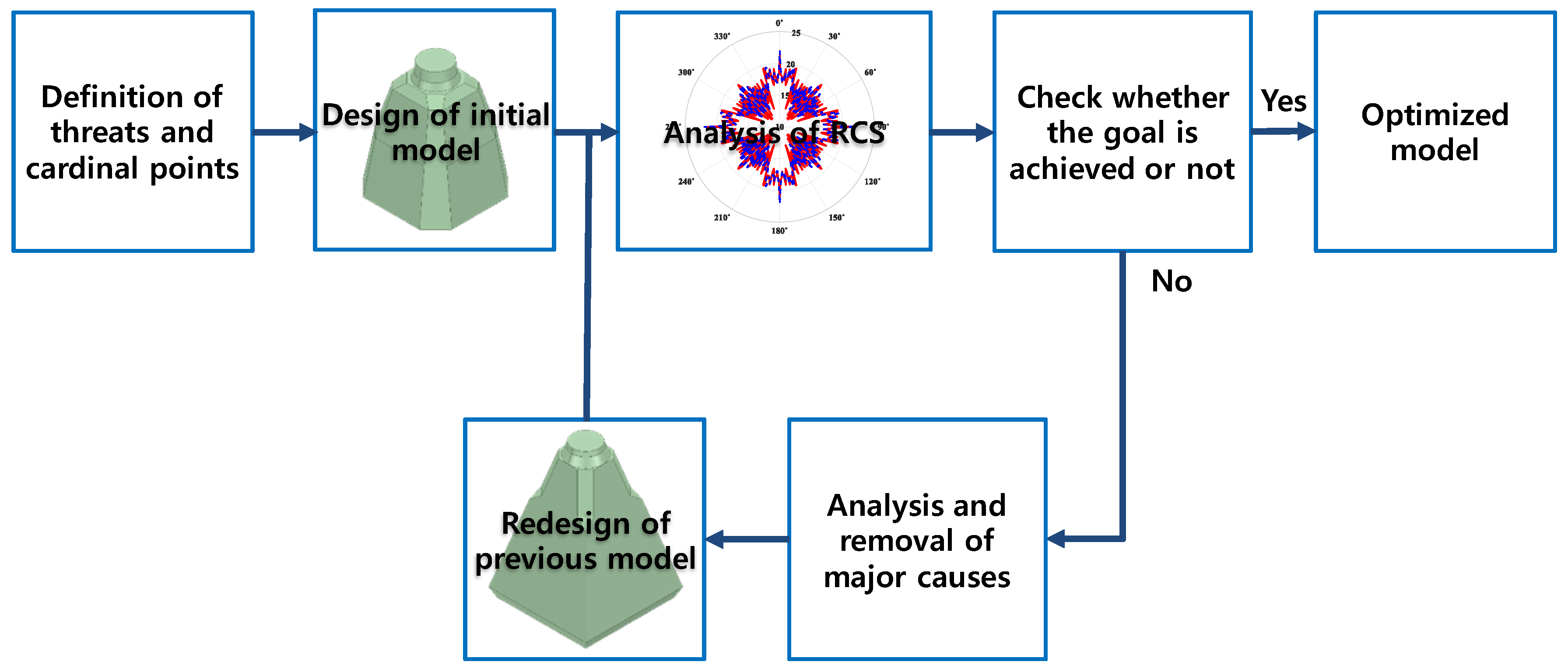
Figure 1. Optimization procedure.
Applsci 11 02819 g001
Figure 2. Cardinal points of the naval vessel.
Applsci 11 02819 g002
Figure 3. Dimension of the integrated mast. (a) initial mast, (b) optimized mast.
Applsci 11 02819 g003
Figure 4. Three-dimensional radar cross section (RCS) pattern of the initial mast. (a) HH polarization in the L-band, (b) VV polarization in the L-band, (c) HH polarization in the S-band, (d) VV polarization in the S-band, (e) HH polarization in the X-band, (f) VV polarization in the X-band. (Unit: dBsm).
Applsci 11 02819 g004
Figure 5. Three-dimensional RCS pattern of the optimized mast. (a) HH polarization in the L-band, (b) VV polarization in the L-band, (c) HH polarization in the S-band, (d) VV polarization in the S-band, (e) HH polarization in the X-band, (f) VV polarization in the X-band. (Unit: dBsm).
Applsci 11 02819 g005aApplsci 11 02819 g005b
Figure 6. RCS pattern of the integrated mast in the azimuth plane in the L-band. (a) HH polarization at an elevation angle of 0°, (b) VV polarization at an elevation angle of 0°, (c) HH polarization at an elevation angle of 10°, (d) VV polarization at an elevation angle of 10°.
Applsci 11 02819 g006
Figure 7. RCS pattern of the integrated mast in the azimuth plane in the S-band. (a) HH polarization at an elevation angle of 0°, (b) VV polarization at an elevation angle of 0°, (c) HH polarization at an elevation angle of 10°, (d) VV polarization at an elevation angle of 10°.
Applsci 11 02819 g007aApplsci 11 02819 g007b
Figure 8. RCS pattern of the integrated mast in the azimuth plane in the X-band. (a) HH polarization at an elevation angle of 0°, (b) VV polarization at an elevation angle of 0°, (c) HH polarization at an elevation angle of 10°, (d) VV polarization at an elevation angle of 10°.
Applsci 11 02819 g008
Figure 9. Geometry and dimension of the naval vessel.
Applsci 11 02819 g009
Figure 10. RCS pattern of a naval vessel equipped with the integrated mast in the azimuth plane in the L-band. (a) HH polarization at an elevation angle of 0°, (b) VV polarization at an elevation angle of 0°, (c) HH polarization at an elevation angle of 10°, (d) VV polarization at an elevation angle of 10°.
Applsci 11 02819 g010
Figure 11. RCS pattern of a naval vessel equipped with the integrated mast in the azimuth plane in the S-band. (a) HH polarization at an elevation angle of 0°, (b) VV polarization at an elevation angle of 0°, (c) HH polarization at an elevation angle of 10°, (d) VV polarization at an elevation angle of 10°.
Applsci 11 02819 g011
Figure 12. RCS pattern of a naval vessel equipped with the integrated mast in the azimuth plane in the X-band. (a) HH polarization at an elevation angle of 0°, (b) VV polarization at an elevation angle of 0°, (c) HH polarization at an elevation angle of 10°, (d) VV polarization at an elevation angle of 10°.
Applsci 11 02819 g012
Table 1. Geometric mean of the integrated mast. (Unit: dBsm)
FrequencyElevation AngleInitial MastOptimized Mast
HHVVHHVV
L-band1.691.75−4.04−4.13
11.2310.40−2.78−2.15
15.7416.32−1.37−4.90
18.0217.553.284.89
10°16.9117.006.024.89
S-band−1.210.03−5.03−3.91
5.687.08−8.94−11.60
14.9215.37−4.49−8.07
20.0520.34−2.31−0.37
10°11.5013.600.573.78
X-band−3.99−3.63−11.12−9.88
−2.21−12.35−9.18−10.69
6.417.92−8.85−4.24
20.2220.14−5.17−1.99
10°1.87−0.54−4.99−4.32
Table 2. Arithmetic mean of the integrated mast. (Unit: dBsm).
FrequencyElevation AngleInitial MastOptimized Mast
HHVVHHVV
L-band5.114.304.20−1.55
11.7810.523.340.12
16.2416.583.770.42
18.3317.737.586.74
10°31.5831.588.686.52
S-band1.350.683.45−1.38
7.307.651.35−3.32
15.2015.481.63−2.41
20.2120.423.772.66
10°34.7334.746.956.64
X-band−0.74−1.53−1.81−8.56
2.46−0.14−0.64−5.98
7.718.48−5.33−3.35
20.2620.150.39−0.30
10°44.3344.33−1.78−2.13
Table 3. Geometrical mean of a naval vessel equipped with the integrated mast. (Unit: dBsm).
FrequencyElevation AngleInitial ShapeOptimized ShapeWithout Mast
HHVVHHVVHHVV
L-band3.952.890.96−1.07−2.15−6.13
11.9811.082.541.86−1.98−2.74
16.0516.613.281.07−1.72−2.60
18.1317.885.906.180.12−1.99
10°17.6217.308.426.892.340.92
S-band1.161.08−1.72−2.27−6.99−11.47
6.777.88−2.81−4.88−7.27−8.26
15.2315.57−0.56−3.02−7.43−7.66
20.0720.230.781.31−5.23−6.44
10°12.3013.913.585.27−2.66−4.30
X-band−3.05−2.97−9.23−8.68−18.13−21.46
−0.87−8.51−6.37−7.61−15.17−16.32
6.798.35−7.11−2.86−15.30−16.68
20.1520.20−3.90−0.82−14.55−15.82
10°3.581.76−2.44−2.04−12.03−13.07
Table 4. Arithmetic mean of a naval vessel equipped with the integrated mast. (Unit: dBsm).
FrequencyElevation AngleInitial ShapeOptimized ShapeWithout Mast
HHVVHHVVHHVV
L-band11.108.7511.008.049.997.26
13.7212.5310.118.999.188.48
17.1017.6310.278.919.067.77
18.8918.6711.2110.869.229.06
10°31.7031.8613.2412.7810.6411.07
S-band9.898.8310.628.479.127.83
10.6211.338.678.588.128.05
16.0016.238.488.037.447.63
20.4520.528.708.697.427.56
10°34.6934.6610.8010.918.359.27
X-band9.668.699.898.449.328.20
8.787.878.798.278.068.03
9.8110.217.056.926.716.39
20.2620.367.288.106.437.07
10°44.3944.419.5710.488.779.94
Publisher’s Note: MDPI stays neutral with regard to jurisdictional claims in published maps and institutional affiliations.