Article

Improvement of Torque Performance and Energy Density of PM-Type Vernier Motor Utilizing Saddle Coil and Salient Pole

1
Collaborative Robots Research Center, Daegu Gyeongbuk Institute of Science & Technology, Daegu 42988, Korea
2
Department of Adaptive Machine Systems, Osaka University, Suita, Osaka 565-0871, Japan
3
Division of Electronics, Information and Communication Engineering, Kangwon National University, Samcheock, Gangwon 25913, Korea
*
Authors to whom correspondence should be addressed.
Appl. Sci. 2021, 11(6), 2818; https://doi.org/10.3390/app11062818
Submission received: 23 January 2021 / Revised: 12 March 2021 / Accepted: 16 March 2021 / Published: 22 March 2021
(This article belongs to the Section Mechanical Engineering)

Abstract

:
In electric motors, the use of rare-earth magnets has been increasing rapidly. A stronger magnet force of the magnet enables the motor’s higher performance, resulting in the most high-performance motors generally using rare-earth magnets. However, these magnets have two crucial disadvantages: the potential restrictions on the supply of rare-earth magnetic materials and the sharp fluctuation in price. Thus, many recent researches focus on developing high-performance electric motors and reducing the use of critical rare-earth magnets. By increasing the torque density of the motor, we can reduce the use of permanent magnets. Focusing on this point, and we presented a double half permanent magnet (DHPM)-type vernier motor. This paper proposed a new saddle coil permanent magnet vernier motor with improved performance compared to its predecessor. The main feature of the proposed motor is that the permanent magnet and coil in the stator of a DHPM-type vernier motor is replaced by salient poles and saddle coils, respectively. We also investigate its characteristics through various simulations.

1. Introduction

With the advancement of the latest high-performance rare-earth magnetic materials, permanent magnet (PM) motors are becoming increasingly popular in various applications ranging from electric and hybrid electric vehicles, and renewable energy systems including wind generators, electric aircraft, and industrial drives. In general, PM motors have two significant advantages. The one is its compact size, and the other is high power density. Due to these advantages, many studies have been conducted on the PM-type vernier motor as a direct-drive motor without a reducer. They provide maintenance-free operation in various applications. In particular, PM plays an essential role for the motor and significantly contributes to improving performance. A stronger magnet force of the magnet enables the motor’s higher performance, resulting in the most high-performance motors generally using rare-earth magnets. However, these magnets have two crucial disadvantages: the potential restrictions on the supply of rare-earth magnetic materials, the sharp fluctuation in price, and the environmental pollution crisis [1,2,3].
Improving the motor’s torque density is the most critical way to reduce the use of PMs significantly. There is also a way to use a high-torque vernier motor at low speeds [4,5,6,7,8,9,10]. A permanent magnet vernier machine with concentrated windings can offer high torque capability at low speed while reducing the number of slots and thus copper loss. In order to improve the power density, the vernier reluctance machine incorporates PMs to provide the excitation, thus becoming the PM vernier (PMV) machine, which includes the single-excitation PMV (SE-PMV)-type [6,8] and the dual-excitation (DE-PMV)-type [7]. The motor designs with PMs on the stator side have been proposed to extend the operational speed range and to decrease the inductance of the electromagnet. However, for the electromagnets, when a three-phase alternating current is applied to the coil at the constant magnetic poles, a short magnetic flux is generated, and there is less increase in performance compared to when a permanent magnet is added to the stator electromagnet because the permanent magnets are fixed. H. Kakihata presented a surface permanent magnet (SPM)-type vernier motor. H. Zhang presented a comparative study of a double-sided toroidal-winding linear PM vernier machine. Among these vernier motors, the design with PMs on both a rotor and a stator, that is, a double half vernier motor, has the highest power density. In particular, we already studied the design with PMs on both the rotor and stator sides and presented a double half permanent magnet (DHPM)-type vernier motor that has a high power density among the other vernier motors [11].
In a previous study [11], we presented the research results that can decrease the number of permanent magnets required in the motor by improving the torque characteristics using a DH vernier motor as a direct-drive system. The research proposed that a new half vernier PM motor is promising as a direct-drive motor. This paper focuses on this point and further improved the torque performance and energy density. It presents a new DHPM vernier motor in which the permanent magnet on the stator is replaced by a salient pole and a saddle coil. As a result, the torque was increased to 4.92 N·m in the proposed motor under the same conditions, compared to 3.85 N·m in its predecessor presented in [11]. The motor’s space volume ratio was also improved by 12% compared to the predecessor. In addition, we use finite element analysis to verify the improved characteristics for torque and energy density of the motor in this paper.
The remainder of this paper is structured as follows: Section 2 discusses works related to the structure and principle of DHPM-type vernier motor. Next, Section 3 shows the performance comparison between the predecessor and the proposed DHPM-type vernier motor. Section 4 presents the comparison of specifications, and it also presents the results and discussion. Finally, Section 5 presents research conclusions and suggestions for future work.

2. Structure and Principle

2.1. A DHPM-Type Vernier Motor

A previously presented DHPM vernier motor, referred to as the predecessor model, is illustrated in Figure 1. Compared to the typical SPM-type vernier motors, a DHPM-type vernier motor has major structural features. It has one half of the magnet in the rotor and the other half of the magnet in the stator. This architecture lets the magnetic flux flow smoothly and increases the torque constant compared to the conventional SPM-type vernier motor.
In the DHPM-type vernier motor, the rotor magneto-motive force (MMF) of the PM (10th order) is modulated by the 12th-order magnetic flux change in the stator. This modulation generates a secondary magnetic flux density distribution in the air gap. Simultaneously, the stator MMF of the PM (12th order) is modulated by the 10th-order permeance change in the rotor to produce a secondary magnetic flux density distribution. Consequently, the modulated rotor and stator are coupled because each side’s modulation order is the same.
A three-phase alternating current is applied to generate a second rotating magnetic field, resulting in the rotation of the rotor. A motor designed with a rotor-half vernier motor reduces the PM by half compared to the conventional SPM-type vernier motor. Similarly, a stator-half vernier motor includes a PM. It is inserted into the electromagnet based on the coil inside the stator slot. Table 1 lists the significant specifications of the DHPM vernier motor.
A conventional DHPM-type vernier motor consists of a PM-type rotor and stator. A DHPM-type vernier motor has a higher torque density than the conventional SPM-type vernier motor due to the high induced voltage. A DHPM-type vernier motor meets the two conditions given in Equations (1) and (2), as follows:
S t N r = N p
N s S r = N p
where
  • St: stator teeth;
  • Nr: poles of the PM of the rotor;
  • Ns: poles of the PM of the stator;
  • Nr: magnetic poles of the rotor;
  • Np: number of coil poles.

2.2. A New DHPM Vernier Motor Using Saddle Coil and Salient Pole

A DHPM-type vernier motor (the predecessor) was prepared to reduce the PMs on the rotor by half. In addition, it reduces the use of PMs on the stator by half by adding a coil-based electromagnet. The result demonstrates that the DHPM-type vernier motor exhibits higher performance than the typical SPM-type counterpart. However, it requires a large number of PMs. Previously, motors employing electromagnet coils and PMs on the stator side—that is, predecessors of this work—have been proposed [12]. Recent studies suggest a design that mounts the magnet near the tooth’s center for motors with PMs on the stator side. This method has the advantages of reducing the electromagnet inductance, increasing the torque integer, and reducing rotational speed.
Due to the fixed polarity of the PM, the motor performance does not increase as expected by generating the short-circuit flux when a three-phase alternating current flows through the stator coils. This result is the case even when the PM has been added to the stator electromagnets.
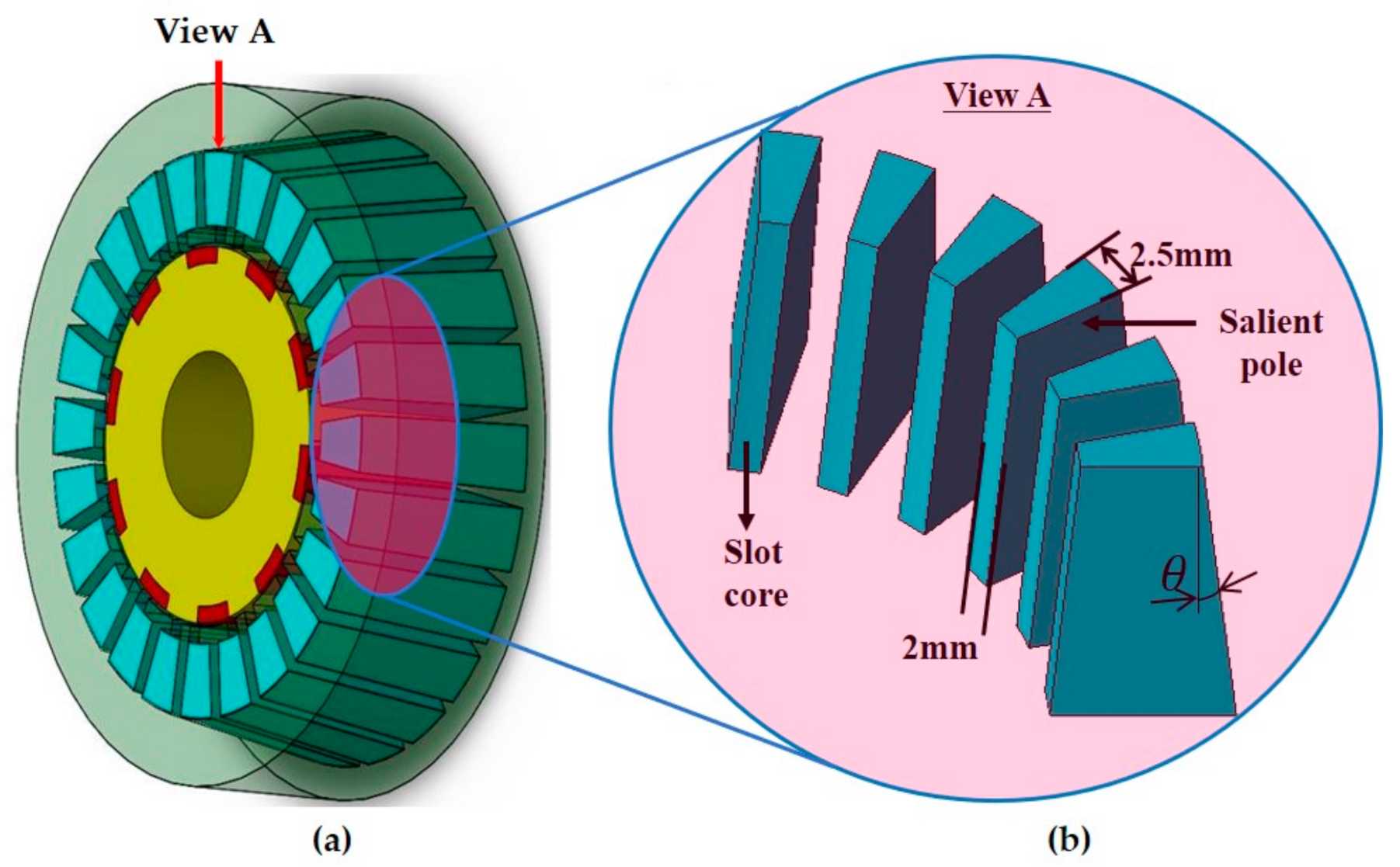
To solve this problem, in the proposed motor, we replaced the PMs in the stator with salient poles and designed them to be inclined to the shape of a stator, as depicted in Figure 2 and Figure 3, respectively. Furthermore, the stator core and salient pole are graded. Therefore, the proposed DHPM vernier motor employs a new saddle-shaped winding coil.
However, Figure 1 displays the shape of the rotor within the predecessor, replacing one of the PM magnetic poles installed in the rotor of the SPM-type vernier motor with a salient pole. The newly proposed model of the new DHPM vernier motor is also of the same construction, and the air gap between the stator and rotor is the same.
The comparison model in Figure 1 (the predecessor) is the DHPM vernier motor with PMs placed on the stator. The proposed models in Figure 2 and Figure 3 are structures arranged by replacing the PMs with salient poles. Furthermore, the salient poles and slot cores are trapezoidal.
Compared to the predecessor model in Figure 1, the proposed model in Figure 2 has the same outer diameter size, and the cross-sectional area is reduced depending on the inclination angle. Thus, the proposed model with saddle coils and salient poles has the advantage that it has greater torque than the comparison model even though it uses the same number of coil windings.
The coils of the predecessor and proposed models are wound using the same pattern, parallel to the axis. The turns of the windings are the same. Thus, the resistance on the coils is almost the same. Moreover, the proposed model reduces the volume and surface area, which proportionally decreases the magnetic resistance.
When the coils are winding to the stator of a newly designed motor, the shape is different from that of a conventional cylindrical motor. If the direction of the coil winding within the slot is called the Z-axis, the stator of the motor newly designed between Z = 0 and Z = x is inclined. The height of the coil wound around the slot by this angle increases linearly, resulting in the shape of the coil winding around the slot core of the teeth’s part being the same as that of the saddle. On the other hand, for a typical cylindrical motor, the height status of the coils in the interval between Z = 0 and Z = x, which are wound in the slot, when observed in the direction of length, is always the same. The maximum external diameter of the newly proposed motor is the same as that of the comparison model. Therefore, the outer diameter of the stator’s end, which is designed to be sloped, is reduced compared to the comparison model. Thus, the width of the coil wound here will be reduced. The coil’s width can be decrease while its height will increase, which will resemble a saddle shape as a whole. As shown in Figure 2, the magnetic path of the proposed motor is reduced. It causes to reduce the magnetic resistance and improve motor performance. A slot fill factor will be decreased by inserting an additional salient pole. In other words, a model with a salient pole will have a lower slot fill factor than a model without a salient pole. We developed a saddle-type model with an angle to reduce the resistance. In this case, the wound coil’s height is slightly higher, but additional space is obtained. It causes that the slot fill factor of the proposed model is increased compared to the model without a salient pole.
Predecessor models are arranged in a stator electromagnet with a PM (the magnetic pole is fixed), but in the structure of the proposed model, the PMs are replaced by a salient pole using the motor’s iron core. The salient pole can be various magnetized magnets, unlike PMs, contributing to the reduction in PMs and the improvement in the torque. Thus, the effect of reducing the magnetic resistance on the change in the shape of the slot core of the proposed model guarantees the increase in the number of magnetic field lines derived from that side of the slot core facing the rotor. As a result, the torque performance is improved significantly. The proposed model presented better performance, even though it has fewer PMs than the other counterparts.
The winding factor is vital as an indicator of the magnetic flux utilization. When the electrical angle is 180 degrees, the magnetic pitch and winding pitch are the same. The short pitch factors are 1 and 0.866 when the electrical angle is 180 degrees and 120 degrees, respectively. We can increase the magnetic flux utilization using PMs and magnetic substances for the salient pole without increasing the magnetic flux density. This result is caused by the winding factor with a change in the electrical angle.
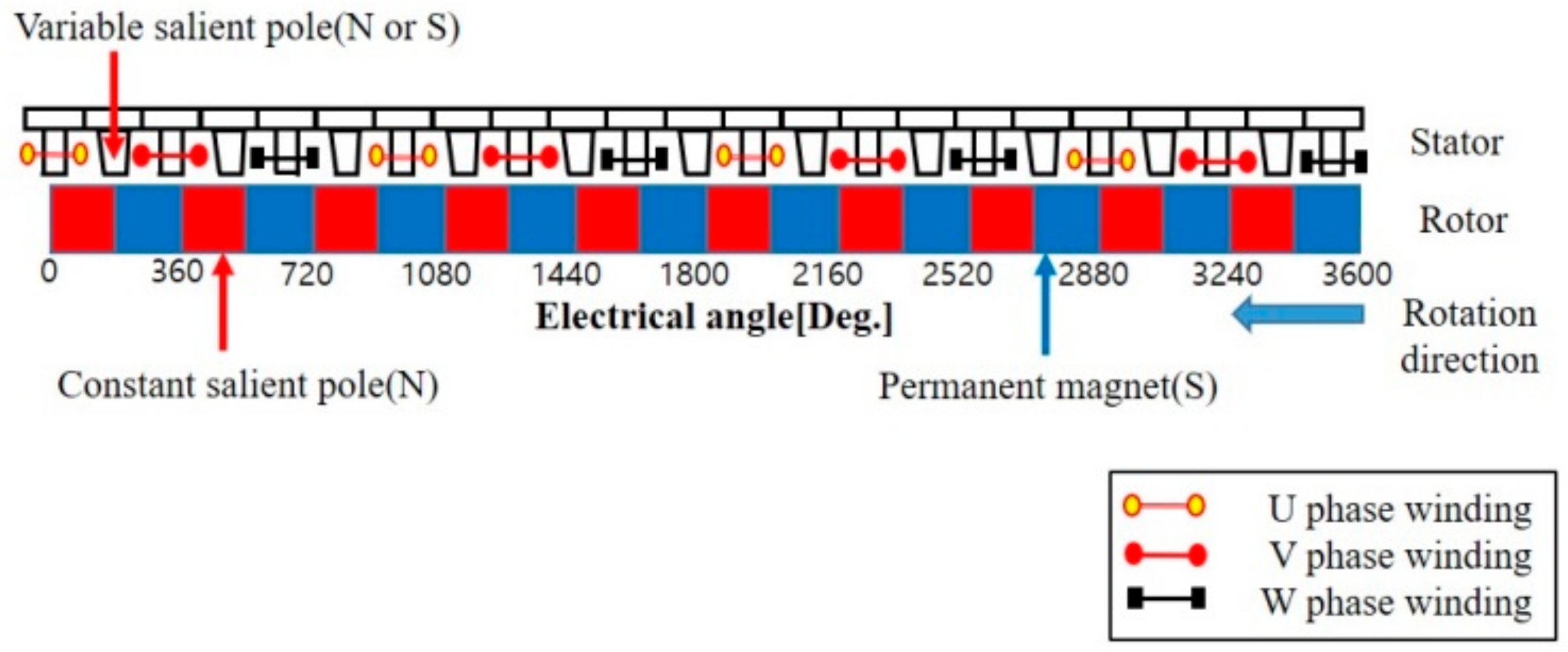
Therefore, a vernier motor of 12S10P for pole pairs in the analytical model has a smaller winding factor. We considered how to increase the magnetic flux density using other factors instead of the winding factor in the motor. Figure 2 depicts the proposed model, which replaces the PM with a magnetic substance (salient pole) and a saddle coil. Additionally, Figure 4 illustrates the deployment chart. The stator structure consists of salient poles without coil windings, and the coils are wound around the center of the slot.
In the proposed rotor structure, several PMs and salient poles are installed sequentially in the circumference to rotate facing the stator teeth.
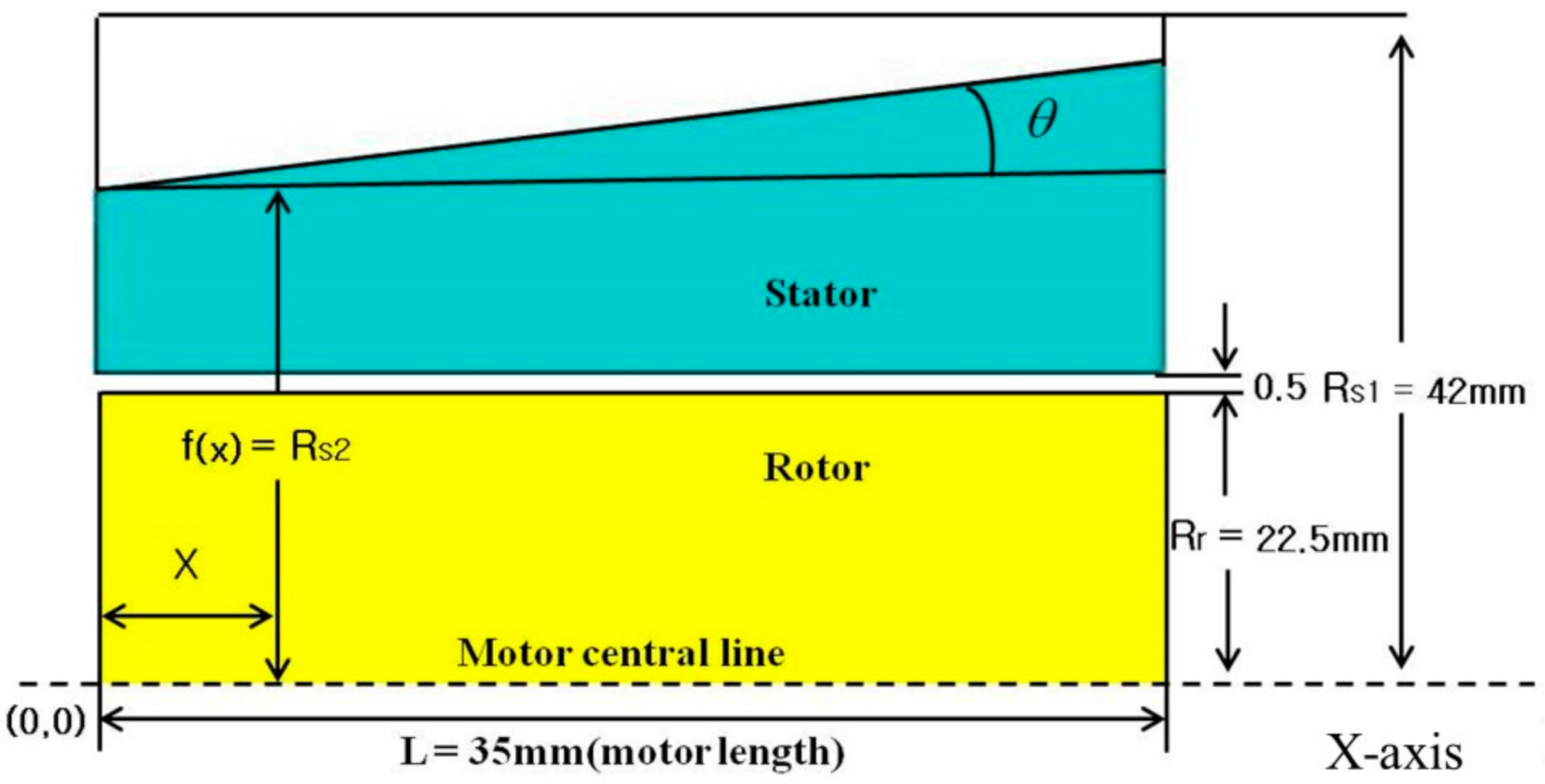
It is essential to increase the energy density, which is the ratio of output to the motor volume, to reduce the motor size and increase the output. As presented in Figure 5, the displacement value at a distance of x from the origin (0, 0) is a function of x, f(x). The area of space, S(x), generated when rotating along the x-axis is obtained from Equation (3).
S ( x ) = 2 π × [ f ( x ) ]
Next, the value of f(x) indicates the distance from the origin (0, 0) of the proposed motor model at the angle of “theta” in Figure 5. This value is obtained from Equation (4), and the motor volume is calculated using Equation (5).
f ( x ) = R s 1 L T a n θ
V = 1 / 3 π ( R s 1 ) 2 + R s 1 R s 2 + ( R s 2 ) 2 L
The predecessor’s cross-sectional area is calculated from s(x) = π{f(x)}2 at f(x) = 42 mm, and the length of the motor, L, is 35 mm. Therefore, the volume of the motor, V1, is the following:
V 1 = π · [ f ( x ) ] · 2 L = π · ( R s 1 ) · 2 L = π · ( 42 ) · 2 × 35 = 193 , 863.6   mm 2
When the inclination angle θ is fixed at 7.5°, the volume of the proposed motor model, V2, is calculated as follows:
V 2 = 1 / 3 π 42 2 + 42 × 42 tan ( 7.5 ) + ( 42 tan ( 7.5 ) 2 × 35 = 173 , 371.8   mm 2
The ratio of the volume of the proposed model to the volume of the predecessor model is the following:
V 2 / V 1 = 173 , 371.8   mm 2 / 193 , 863.6   mm 2 × 100 % = 89 %
From the above equations, the current density of the proposed motor model increases as the inclination angle increases. The proposed model’s motor space utilization efficiency also improved more than the previously presented DHPM vernier motor model due to the motor volume improvement.

3. Performance Comparison of the Proposed and Other Models

Table 2 presents the comparison results for the back EMF and torque according to the vernier motor classification, including the SPM vernier motor, rotor-half, stator-half, and DHPM-type vernier motors. The back EMF and torque of the stator-half PM-type vernier motor are much lower than those of the SPM vernier motor.
The DHPM vernier motor attempts to increase motor performance by installing additional PMs in the slot to combine the electromagnet’s MMF with that of the PM. However, as listed in Table 2, some performance improved but not satisfactorily. In other words, the best performance is exhibited by the DHPM vernier motor that has added PMs to the stator in the structure of the rotor, which was replaced by salient poles to reduce the PMs by half. However, the model has not achieved satisfactory performance due to the short-circuit flux. Thus, we chose this as a comparative model and proposed a new concept model.

4. Comparison of Specifications of the DHPM-Type Vernier Motor for the Proposed DHPM Vernier Motor and Compatible Model

Table 3 lists the specifications for the proposed models. If the inclination angle is 0° for the conventional model [11], the proposed model has the same structure except for the inclination angle, 7.5°. However, due to the three-phase alternating current flows, the polarity and strength of the electromagnet vary depending on the phase angle. Nevertheless, the polarity of the PM remains fixed. Therefore, the motor performance cannot be improved as expected due to a large magnetic short circuit.
As presented in Table 2, the comparison model has better performance than the other models. We cannot achieve the expected effect of increasing the magnetic flux density using PMs in the stator due to magnetic flux short circuits. The saddle coil in a motor designed with the new concept is used to minimize the motor volume with a typical cylindrical structure.
The new idea for this motor is to design the stator exterior with a slope in the direction of the motor length, as depicted in Figure 2. We can reduce the volume in the designed motor compared to conventional motors, as displayed in Figure 1. This reduction is due to shortening the length of the stator’s magnetic circuit, causing a reduction in magnetic resistance to the magnetic circuit and resulting in more efficient use of the magnetism generated by the coils installed in the stator. When the coils are winding in the stator in the newly designed motor, the shape is different from that of a conventional cylindrical motor. If the coil winding direction within the slot is on the z-axis, the stator has a new design with an inclination angle between 0 and x degrees. Thus, the coil height around the slot using this angle increases linearly, resulting in the same shape of coil winding around the slot core of the teeth part as that of the saddle.
However, a typical cylindrical motor has the same height status of the coils between z = 0 and z = x when observed in the length direction. The maximum external diameter of the newly proposed motor is the same as that of the predecessor model. Therefore, the stator’s outer diameter is sloped and reduced compared to that of the predecessor. Thus, the wound coil width is reduced.
The coil width can be decreased, whereas its height increases, resulting in an overall saddle shape. As illustrated in Figure 2, the magnetic path of the proposed motor is reduced, reducing the magnetic resistance and improving the motor performance, as indicated in Equation (9):
B = μ N I L
A longer magnetic path causes greater magnetic resistance and lower magnetic density. In contrast, a shorter magnetic path causes a greater magnetic density. In Equation (9), B denotes the magnetic field, μ is the permeability, N indicates the number of turns, I denotes the current, and L represents the length of the magnetic path. In other words, Figure 2 indicates that the length of the magnetic path is shorter than that in Figure 1, resulting in less magnetic resistance and increased magnetic density.
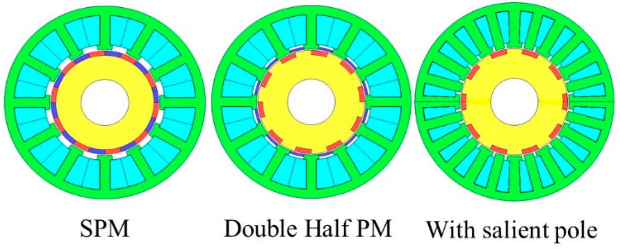
As presented in Figure 6, a salient pole is used to generate magnetic poles according to the electromagnet polarity. Installing the salient pole has advantages in solving the problem due to magnetic short circuits and reducing the use of PMs using rare-earth elements.
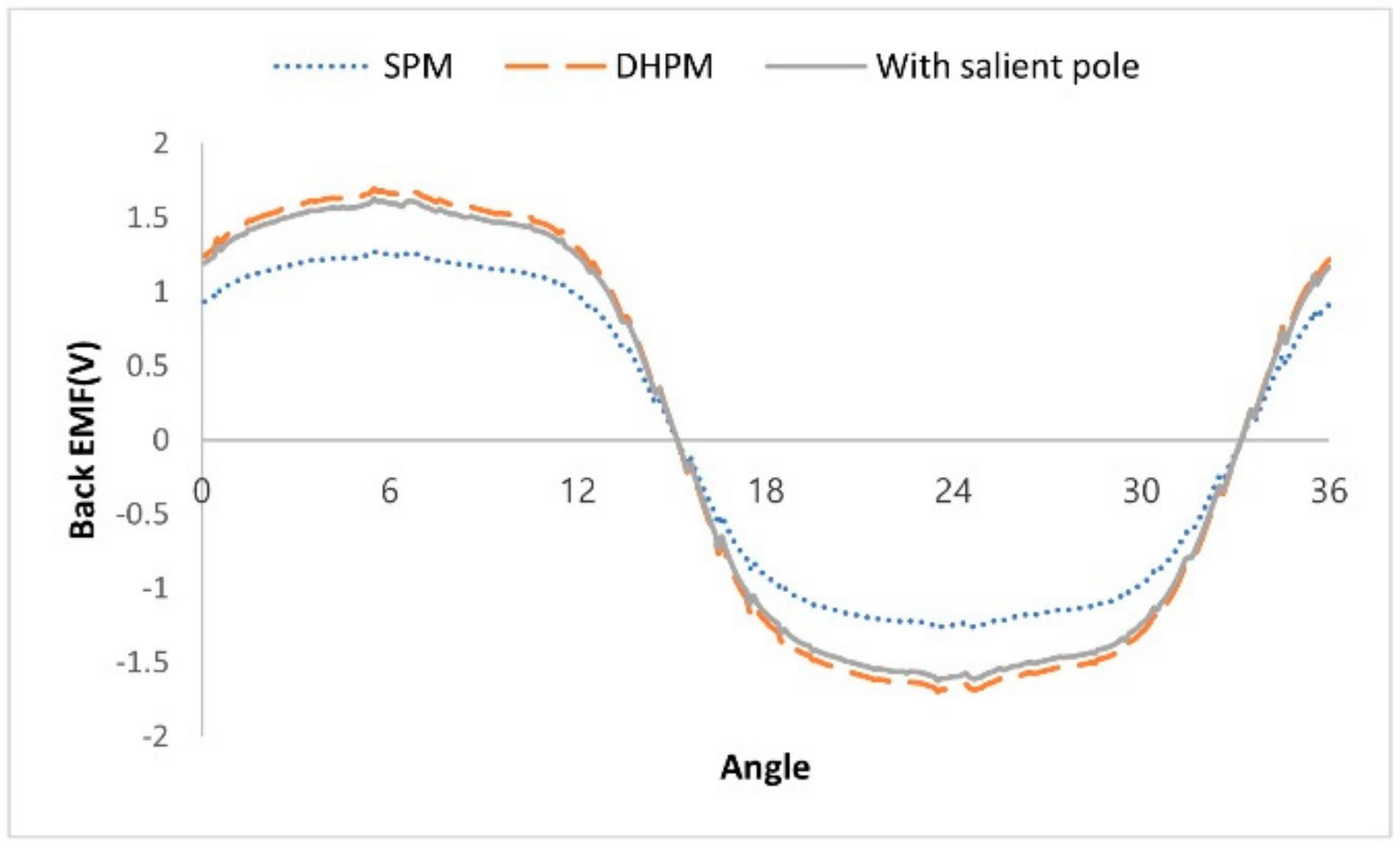
In Figure 7, we compare the inductive voltage of the SPM, DHPM, and model “with salient poles.” The induced voltage is (1) 1.24 V for the SPM vernier motor, (2) 1.61 V for the model with salient poles, and (3) 1.68 V for the DHPM motor. The comparison results indicate that the motor performance with salient poles is similar to or better than that of the DHPM.
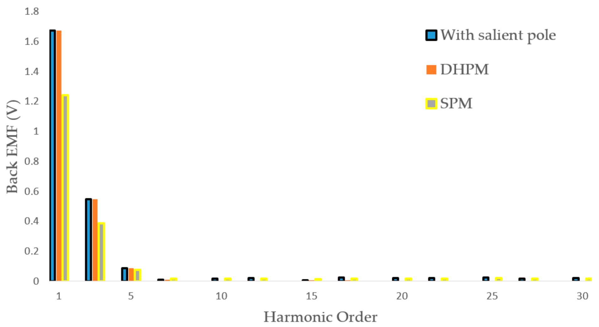
As displayed in Figure 8, the back EMF of the inductive voltage is similar to the DHPM model with only PMs in the stator or a model with salient poles to replace the PMs. The magnetic flux in the DHPM vernier motor is more robust than that in the SPM motor. However, the generated magnetic flux is limited between the teeth and rotor because it does not move sufficiently. Figure 9 presents the magnetic flux flow that occurs when replaced by salient poles instead of a PM in the slot in the DHPM vernier motor. Moreover, the magnetic flux density and flow pattern are similar to the motor model with a salient pole.
Table 3 presents the comparison results of the performance of the SPM and proposed DHPM vernier motor using saddle coils with salient poles. The SPM and DHPM vernier motors have no slope, but the proposed DHPM vernier motor replaces the PM in the stator with the salient poles, employing an inclination angle. In addition, the coils of the predecessor and proposed model are wound in the same slot evenly. Moreover, the number of turns is the same, so resistance values are about the same.
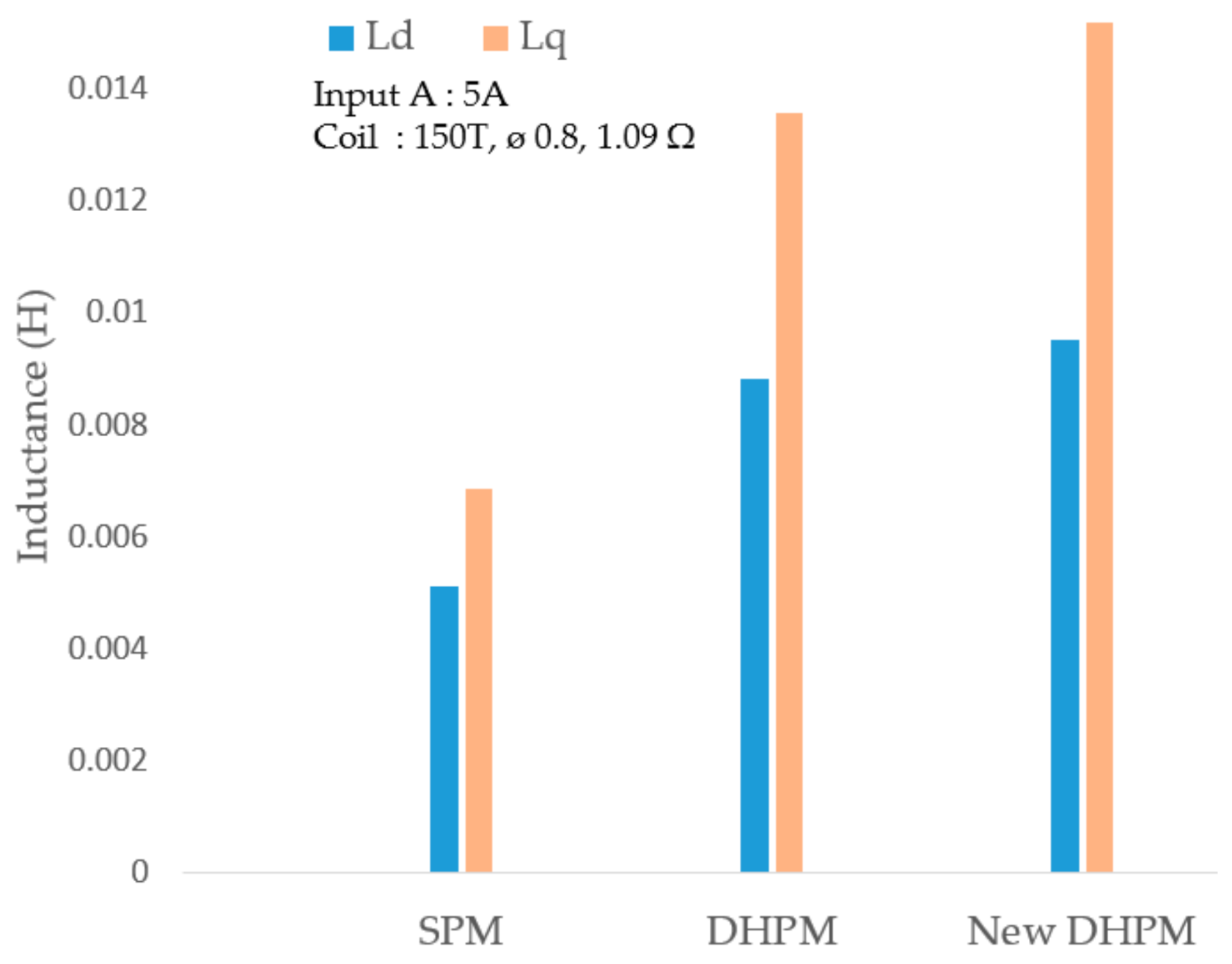
The proposed model focuses on reducing the magnetic resistance due to the smaller space and the circumference’s smaller surface area. The inclination angle changed from 0° to 7.5°. From the comparison results, the maximum external stator diameter is 82 mm, and the motor length is 35 mm. The air gap is 0.5 mm, and the coil diameter is 0.8 mm. The external rotor diameter is 42 mm, and the thickness of the PMs is 2 mm. The inclination angle between the stator’s surface circumference and the axis of rotation of the rotor is 7.5°. In a motor, as the magnetic flux of the d-axis transmits a low permeability magnet, the inductance is low, and the magnetic flux of the q-axis passes through the iron core. Consequently, the magnetic permeability is greater, and the inductance of the q-axis is greater than the inductance of the d-axis. The d-axis and q-axis are always rotated with an angle of 90° to the electrical angle.
Figure 10 depicts the comparison results for the inductance of the d-axis and q-axis at the SPM vernier motor, the predecessor, and the proposed model. Moreover, Ld is smaller than Lq in the Ld-axis and Lq-axis, whereas Lq is larger in the proposed model than in the predecessor. The proposed model has higher torque than the predecessor model because Ld is also larger in the proposed model than in the predecessor.
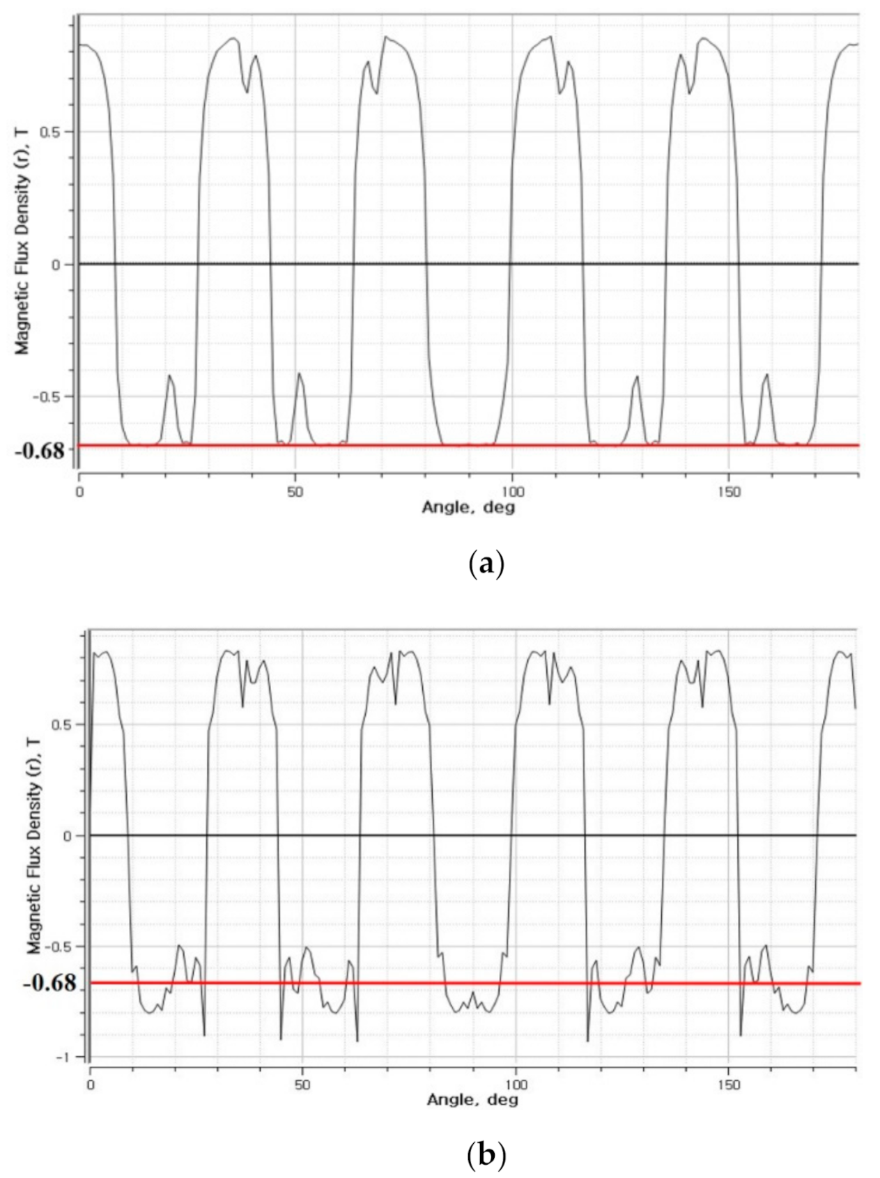
Figure 11 reveals that the magnetic flux flow when the inclination angle is between the stator core’s internal circumference surface and the rotational axis is 7.5° in the presence of a salient pole of teeth. The figure indicates that the magnetic flux density significantly increased. Figure 12 depicts the flux density of (a) the DHPM vernier motor with a salient pole with a peak value of 0.7 and (b) the proposed model with a higher peak value (>0.8).
Therefore, we discovered that the proposed model creates a strong magnetic field by combining the salient poles and saddle types. The coils for both the predecessor and proposed model have the same conditions, such as the direction, shape, and number of turns. Therefore, the resistance value of the winding coil is the same. In the proposed DHPM model, the space occupied by the motor is small, and the surface area of the circumference is small, which reduces the magnetic resistance.
As a result that the slot space inside the stator limits the number of coil windings and the space factor, the inclination angle should be designed carefully with optimum values. The proposed model with a saddle coil achieves high torque because the interlinkage magnetic flux in the air gap is increased by the rate of the magnetic strength of the coil electromagnet. The density of interlinkage magnetic flux by the salient pole is also increased.
Therefore, we increase the slope angle. The simulation result reveals that the proposed model generates a higher magnetic flux density and space utilization than the predecessor model. In the proposed model, the space volume ratio is 89% of the predecessor model at an inclination angle of 7.5°. The volume decreased by 11%. Thus, the space utilization efficiency increased significantly. This simulation result demonstrates that increasing the inclination angle improves motor performance and space utilization efficiency. Consequently, the energy density per unit volume and weight have improved significantly.
In general, motor designs replacing PMs and increasing PMs instead of coils in the stator and rotor to miniaturize motors and improve motor performance are common [13,14,15,16]. A dual structure that increases the number of rotors and stators to improve performance has also been attempted [16,17,18,19]. However, the proposed model increases the slope angle by applying saddle coils and salient poles, improving performance and space utilization efficiency.
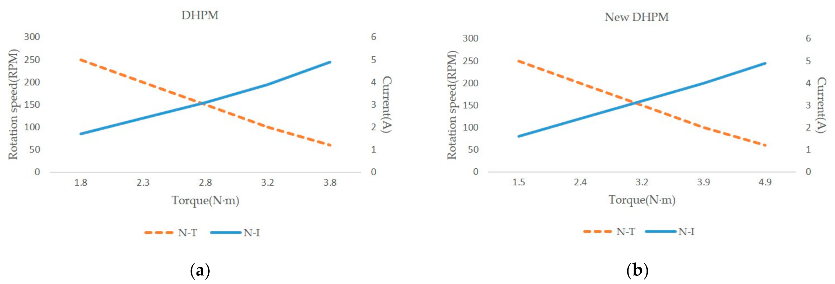
Figure 13 compares the N-T and N-I characteristics of the predecessor and proposed models. Each model is connected using a Y connection with 12 V and a coil resistance of 1.09 ohms.
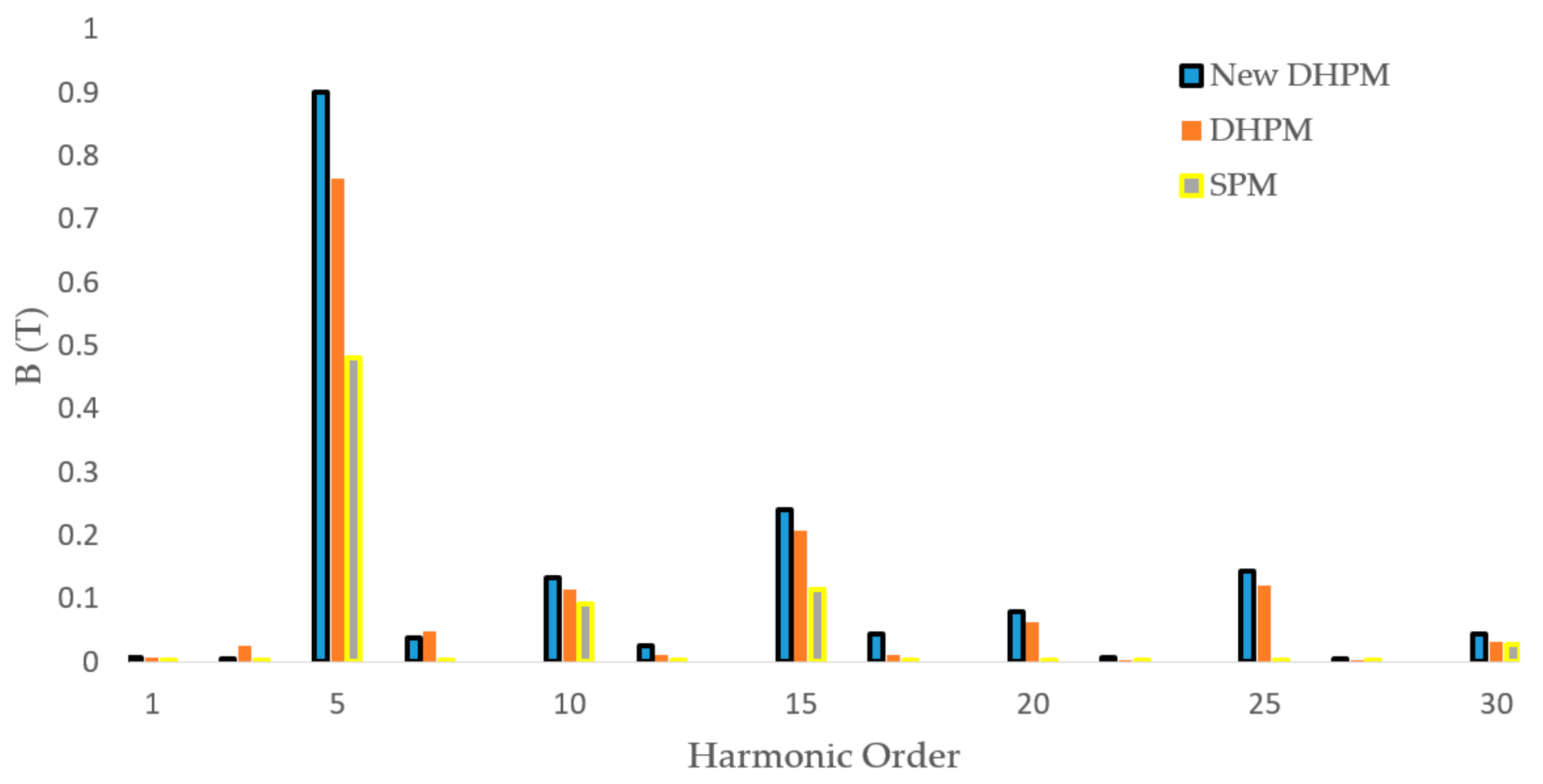
We compared the proposed DHPM vernier motor (inclination 7.5°) and a typical DHPM motor [11] with a non-load rotational speed (rpm) and starting maximum torque (N∙m). Table 4 compares the performance of SPM and predecessor models to the proposed DHPM model. Torque constant, Kt, has to be the proportionality factor for a given motor current, and it is torque equivalent. T (torque) axis can also be replaced by I (current) axis accordingly. The comparison results confirm that the proposed DHPM vernier motor may produce higher torque at lower speeds than a conventional motor. The harmonic order of the 5th, 10th, and 15th sequence (T) in Figure 14 demonstrates that the proposed DHPM vernier motor has a higher value of flux density than a conventional DHPM motor. The results are summarized in Table 5.

5. Conclusions

This paper proposes a new DHPM vernier motor prepared by replacing the PMs on the stator of a conventional DHPM-type vernier motor, employing salient poles and substituting a saddle coil. We analyzed the various features of the proposed DHPM vernier motor using precise simulations.
  • The proposed model was prepared by replacing the stator’s PMs with salient poles. The analysis results demonstrate that the induced voltage is almost equal to that of the DHPM-type vernier motor prepared by adding PMs to electromagnets.
  • We prepared the proposed model by setting the inclination angle at 7.5°. The high torque of the proposed model confirms its effectiveness. The change rate in the interlocking magnetic flux of the coil increased. In addition, the area of the interlinkage magnetic flux of the silent pole increased with the change in the inclination angle. In the proposed DHPM-type vernier motor to which the angle was applied, the interlinkage magnetic flux area of the salient pole and the temporal change rate in the interlinkage magnetic flux of the stator increased by the inclination angle. Additionally, a greater torque was obtained, and its effectiveness was confirmed.
  • Compared with the other motors, such as the SPM-type vernier motor and DHPM-type vernier motor, the magnetic flux density of the proposed DHPM vernier motor increased depending on the inclination angle. The space volume ratio improved at the inclination angle of 7.5°, which proves that the space utilization efficiency increased and both the energy density per unit volume and per unit weight improved.
  • By comparing the load-free rotation number (rpm) and the maximum torque (Nm) when starting a proposed DH vernier motor and a conventional DH vernier motor, we demonstrated that the proposed DHPM vernier motor can produce lower-speed high-torque characteristics. Following this research, research on design optimization and miniaturization will be conducted by comparing the performance and analyzing the magnetic flux density with the inclination angle (or the like) to improve the energy density per unit volume and per unit weight for practical use for a new DHPM vernier motor.

Author Contributions

Conceptualization, S.C., N.N., and K.H.; methodology, S.C. and N.N.; software, S.C.; validation, S.C., J.-H.L., and K.H.; formal analysis, S.C. and N.N.; investigation, S.C.; resources, S.C. and K.H.; data curation, S.C.; writing—original draft preparation, S.C.; writing—review and editing, J.-H.L. and K.H.; visualization, S.C.; supervision, J.-H.L. and K.H.; project administration, S.C.; funding acquisition, S.C. and K.H. All authors have read and agreed to the published version of the manuscript.

Funding

This work was supported by the DGIST R&D Program of the Ministry of Science, ICT and Future Planning of Korea (19-ST-01). This study has been worked with the support of a research grant of Kangwon National University in 2016.

Institutional Review Board Statement

Not applicable.

Informed Consent Statement

Informed consent was obtained from all subjects involved in the study.

Data Availability Statement

Data sharing not applicable.

Conflicts of Interest

The authors declare no conflict of interest.

References

  1. El-Refaie, A.; Raminosoa, T.; Reddy, P.; Galioto, S.; Pan, D.; Grace, K.; Alexander, J.; Huh, K. Comparison of traction motors hat reduce or eliminate rare-earth materials. In Proceedings of the IEEE Energy Conversion Congress and Exposition, Milwaukee, WI, USA, 18–22 September 2016; pp. 1–8. [Google Scholar]
  2. Takeno, M.; Chiba, A.; Hoshi, N.; Ogasawara, S.; Takemoto, M.; Rahman, M. Test results and torque improvement of the 50-kw switched reluctance motor designed for hybrid electric vehicles. IEEE Trans. Ind. Appl. 2012, 48, 1327–1334. [Google Scholar] [CrossRef]
  3. Petrov, I.; Pyrhönen, J. Performance of Low-Cost Permanent Magnet Material in PM Synchronous Machines. IEEE Trans. Ind. Electron. 2013, 60, 2131–2138. [Google Scholar] [CrossRef]
  4. Ishizaki, A.; Tanaka, T.; Takasaki, K.; Nishikata, S.; Watanabe, K.; Katagiri, A. Theory and torque characteristics of PM vernier motor. IEEJ Trans. Ind. Appl. 1993, 113-D, 1192–1199. [Google Scholar] [CrossRef] [Green Version]
  5. Lee, C.H. Vernier motor and its design. IEEE Trans. Power App. Syst. 1963, 82, 343–348. [Google Scholar] [CrossRef]
  6. Toba, A.; Lipo, T.A. Generic torque-maximizing design methodology of surface permanent-magnet vernier machine. IEEE Trans. Ind. Appl. 2000, 36, 1539–1546. [Google Scholar]
  7. Atallah, K.; Rens, J.; Mezani, S.; Howe, D. A novel pseudo direct-drive brushless permanent magnet machine. IEEE Trans. Magn. 2008, 44, 4349–4352. [Google Scholar] [CrossRef]
  8. Ishizaki, A.; Shibata, Y.; Watanabe, K.; Saito, K. Low speed high torque drive system applying vernier motor torque. IEEJ Trans. Ind. Appl. 1991, 111, 785–793. [Google Scholar] [CrossRef] [Green Version]
  9. Kakihata, H.; Kataoka, Y.; Takayama, M.; Matsushima, Y.; Anazawa, Y. Design of surface permanent magnet-type vernier motor. J. Int. Conf. Electr. Mach. Syst. 2013, 2, 127–133. [Google Scholar] [CrossRef] [Green Version]
  10. Zhang, H.; Shao, Y.; Kou, B.; Qu, R.; Zhu, Q. Comparative study of double-sided toroidal-winding linear PM vernier machines with different secondary configuration. In Proceedings of the ICEMS 2017, Sydney, Australia, 11–14 August 2017; pp. 1–5. [Google Scholar]
  11. Chang, S.; Hirata, K.; Niguchi, N. Torque performance enhancement of PM-type vernier motor utilizing saddle coil and salient pole. In Proceedings of the 22nd International Conference on Electrical Machines and Systems, Harbin, China, 11–14 August 2019; pp. 1–6. [Google Scholar]
  12. Toba, A.; Lipo, T.A. Novel dual-excitation permanent magnet vernier machine. In Proceedings of the 34th IAS Annual Conference, Phoenix, AZ, USA, 3–7 October 1999; pp. 2539–2544. [Google Scholar]
  13. Zhu, Z.Q.; Cai, S. Hybrid excited permanent magnet for electric and hybrid electric vehicles. CES Trans. Electr. Mach. Syst. 2019, 3, 233–247. [Google Scholar] [CrossRef]
  14. Reichert, T.; Kolar, J.W.; Nussbaumer, T. Stator tooth design study for bearingless exterior rotor PMSM. IEEE Trans. Ind. Appl. 2013, 49, 1515–1522. [Google Scholar] [CrossRef]
  15. Akemakou, A.D.; Phounsombat, S.K. Electrical Machine with Double Excitation, Especially a Motor Vehicle Alternator. U.S. Patent 6 147 429, 2000. [Google Scholar]
  16. Lee, C.H.T.; Angle, M.; Bhalla, K.K.; Qasim, M.; Mei, J.; Mohammadi, S.; Iyer, K.L.V.; Sinkular, J.J.; Kirtley, J.L. Quantitative comparison of vernier permanent-magnet motors with interior permanent-magnet motor for hybrid electric vehicles. Energies 2018, 11, 2546. [Google Scholar] [CrossRef] [Green Version]
  17. Thiele, M.; Heins, G. Computationally efficient method for identifying manufacturing induced rotor and stator misalignment in permanent magnet brushless machines. IEEE Trans. Ind. Appl. 2016, 52, 3033–3040. [Google Scholar] [CrossRef]
  18. Li, D.; Zou, T.; Qu, R.; Jiang, D. Analysis of fractional-slot concentrated winding PM vernier machines with regular open-slot stators. IEEE Trans. Ind. Appl. 2017, 54, 1320–1330. [Google Scholar] [CrossRef]
  19. Shil, Y.; Niu, S.; Wei, J.; Jian, L.; Liu, R. Comparison between dual-permanent-magnet-excited machines with fewer stator poles and fewer rotor poles. IEEE Trans. Magn. 2015, 51, 1–4. [Google Scholar]
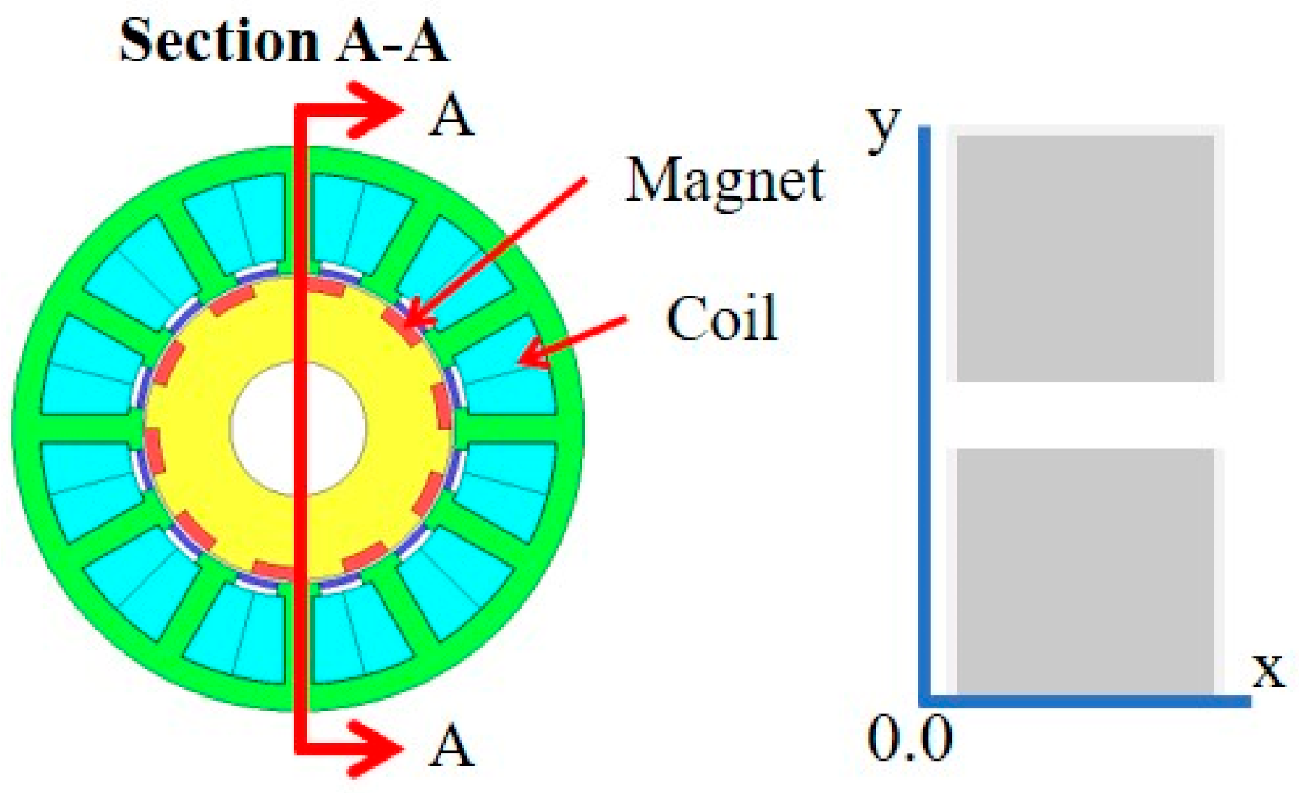
Figure 1. Conventional double half permanent magnet (DHPM)-type vernier motor (predecessor).
Applsci 11 02818 g001
Figure 2. Newly presented double half permanent magnet (DHPM)-type vernier motor.
Applsci 11 02818 g002
Figure 3. Design of the new double half permanent magnet (DHPM) vernier motor; (a) New DHPM vernier motor, (b) The shape of slot cores and salient poles on the inclination.
Applsci 11 02818 g003
Figure 4. Deployment chart of the new double half permanent magnet (DHPM) vernier motor.
Applsci 11 02818 g004
Figure 5. Side view of the proposed double half permanent magnet (DHPM) vernier motor.
Applsci 11 02818 g005
Figure 6. Comparison of the surface permanent magnet (SPM) vernier motor, double half permanent magnet (DHPM) (with a PM in the stator) motor, and model with salient poles.
Applsci 11 02818 g006
Figure 7. Comparison of the induced voltage of the surface permanent magnet (SPM) vernier motor, double half permanent magnet (DHPM) motor, and motor with salient poles.
Applsci 11 02818 g007
Figure 8. Comparison of the harmonic order of the surface permanent magnet (SPM) vernier motor, double half permanent magnet (DHPM) motor, and motor with salient poles.
Applsci 11 02818 g008
Figure 9. Magnetic flux flow in the model with salient poles.
Applsci 11 02818 g009
Figure 10. Comparison of the inductance Ld, Lq of the surface permanent magnet (SPM) vernier motor, typical double half permanent magnet (DHPM) motor, and proposed DHPM motor.
Applsci 11 02818 g010
Figure 11. Comparison of the flux flow of the proposed double half permanent magnet (DHPM) vernier motor and other counterparts.
Applsci 11 02818 g011
Figure 12. Comparison magnetic flux density in an air gap between the proposed and predecessor models. (a) Double half permanent magnet (DHPM) vernier motor with salient poles. (b) Proposed double half permanent magnet (DHPM) vernier motor.
Applsci 11 02818 g012
Figure 13. Comparison of N-T and N-I graphs: (a) DHPM, (b) new DHPM.
Applsci 11 02818 g013
Figure 14. Comparison of the air gap field generated by the three-phase winding of the harmonic order.
Applsci 11 02818 g014
Table 1. Major specifications.
Air gap length0.5 mm
Coil0.8 mm, 1.09 Ω
Coil turn number150
Magnetic thickness2 mm
Outside diameter84 mm
Thickness35 mm
Table 2. Comparison results of the double half permanent magnet (DHPM)-type vernier motor with typical surface permanent magnet (SPM), rotor-half PM, and stator-half PM motors.
ItemsClassification of the Vernier Motor
SPMRotor HalfStator HalfDouble Half
Back EMF [V]1.241.180.261.68
Torque [N∙m]2.422.400.493.85
Table 3. Specification of the proposed DHPM vernier motor.
ItemsNew DHPM Vernier Motor
Angle of inclination of saddle motor7.5°
Maximum Outside diameter82 mm
Motor length35 mm
Air gap length0.5 mm
Coil0.8 mm, 1.09 Ω
Coil turn number150
Magnetic material50JN400
Table 4. Performance comparison of the surface permanent magnet (SPM), conventional double half permanent magnet (DHPM), and proposed DHPM-type vernier motors.
ItemsSPMA Conventional DHPM Vernier MotorA Proposed DHPM
Vernier Motor
Saddle motor inclination angle7.5°
Coil turn number150 turn
Torque constant, Kt (N∙m/A)0.4840.770.984
Back EMF1.241.682.25
Torque2.423.854.92
Space volume ratio of motor110.89
Ld(H)0.0051300.0088140.009514
Lq(H)0.0068660.0135730.015190
Table 5. Harmonic analysis results of the waveform.
ItemsMagnetic Flux (T)
SPMA Conventional DHPM Vernier MotorA New DHPM
Vernier Motor
50.4808190.7633850.899748
100.0908190.1138960.132117
150.1138960.2078680.239260
Publisher’s Note: MDPI stays neutral with regard to jurisdictional claims in published maps and institutional affiliations.