
Design, Modeling, and Simulation of a Wing Sail Land Yacht


Abstract
Featured Application
Abstract
1. Introduction
- Landis et al. [10,14] propose the National Aeronautics and Space Administration (NASA) Zephyr land sailing rover. It is intended to be used in Venus, a harsh, windy planet. The conceptual design uses a NACA0015 airfoil with a wingspan of 5.44 m, a lateral area of 12 m2, and weight of 49 kg. The chassis has a triangular shape with three wheels and weighs 35 kg.
- Xie et al. [11] present the Autonomous Controlled Four-Wheeled Land Yacht concept. This land vehicle is propelled by a single wing sail with a symmetrical profile, 1 m wingspan, a lateral area of 0.25 m2, a mass of 2.15 kg, and a rotation range of 0°–360°. The chassis is composed by an aluminium hull and two front and two rear wheels with a total mass of 19 kg.
- Chen et al. [15] propose the Multiple Wing Sail Land Yacht. It adopts a triple wing sail design to reduce the wind velocity required to start the vehicle motion. The remaining features are equal to those of the previous example.
- Zhu et al. [13] adopt a free-rotating NACA0015 wing sail with a wingspan of 2.5 m and a lateral area of 1.25 m2 design to rig a land yacht. The steel chassis has one front wheel and two rear wheels. Although not fully autonomous, the angle of attack of the free-rotating wing sail is set by controlling the tail flap, which induces torque on the wing sail.
- Mirzaei et al. [16] describe a land yacht developed with a NACA0012 airfoil. The airfoil has a wingspan of 1 m and a lateral area of 0.5 m2. The chassis has a triangular shape with a front wheel and two rear wheels and has a mass of 8 kg.
- Dong et al. [17] describe a land yacht with a wing sail and a chassis. The NACA0015 airfoil has a wingspan of 0.8 m, a lateral area of 0.24 m2, and a rotation range of 0°–270°. The chassis has four steel wheels and plastic frame.
- Reina et al. [18] detail a land yacht model which has a NACA0012 airfoil with a wingspan of 3 m and a lateral area of 2 m2. The triangular chassis has three wheels and weighs 100 kg.
- Chen et al. [23] derive a mathematical model for a four-wheel land yacht powered by a wing sail. They model the structure, steering gear, servomotors and force of wing sail and, then, simulate the motion of land yacht according to the mathematical model. The mathematical model analyzes both the linear and steering motions. The simulation and actual experimental results confirm the feasibility and reliability of the proposed land-yacht modeling.
- Dong et al. [17] present the design, simulation and development of a wind-driven land yacht propelled by a wing sail. The authors conduct a theoretical analysis and use ANSYS Fluent simulation software to determine the lift and drag coefficients corresponding to each combination of attack and heading angles, and the best attack angle corresponding to each different heading angle. The simulation and experimental upwind results were concordant.
- Rynne and von Ellenrieder [24] design, simulate and develop a wind (rigid wing sail) and solar-powered autonomous surface vehicle (ASV). Before building the ASV, the control simulation was performed with a velocity prediction program (VPP). Initial field trials showed that the experimental and simulated boat speeds and wind speed/directions were consistent.
- Enqvist et al. [25] design and simulate a simple, reliable and highly autonomous sailboat. They choose a symmetrical, free-rotating wing sail with an additional tail for actuating the wing and controlling its angle of attack. The design was further investigated with a computation flow dynamics simulation software.
- Augenstein et al. [26] design and simulate small ( 1 ) semi-autonomous robotic sailboat platform variants equipped with a symmetric airfoil sail, a thin, bulbed keel, and a tail-vane rudder, replacing the traditional water rudder. They adopt MATLAB to perform 2D and 3D dynamic simulations of the tail-vane rudder design.
- Setiawan et al. [27] design and simulate an autonomous sailboat dynamic model with four degrees of freedom. The simulations were carried out with MATLAB/Simulink to determine the effect of flap and rudder deflection angles on boat dynamics.
2. Materials and Methods
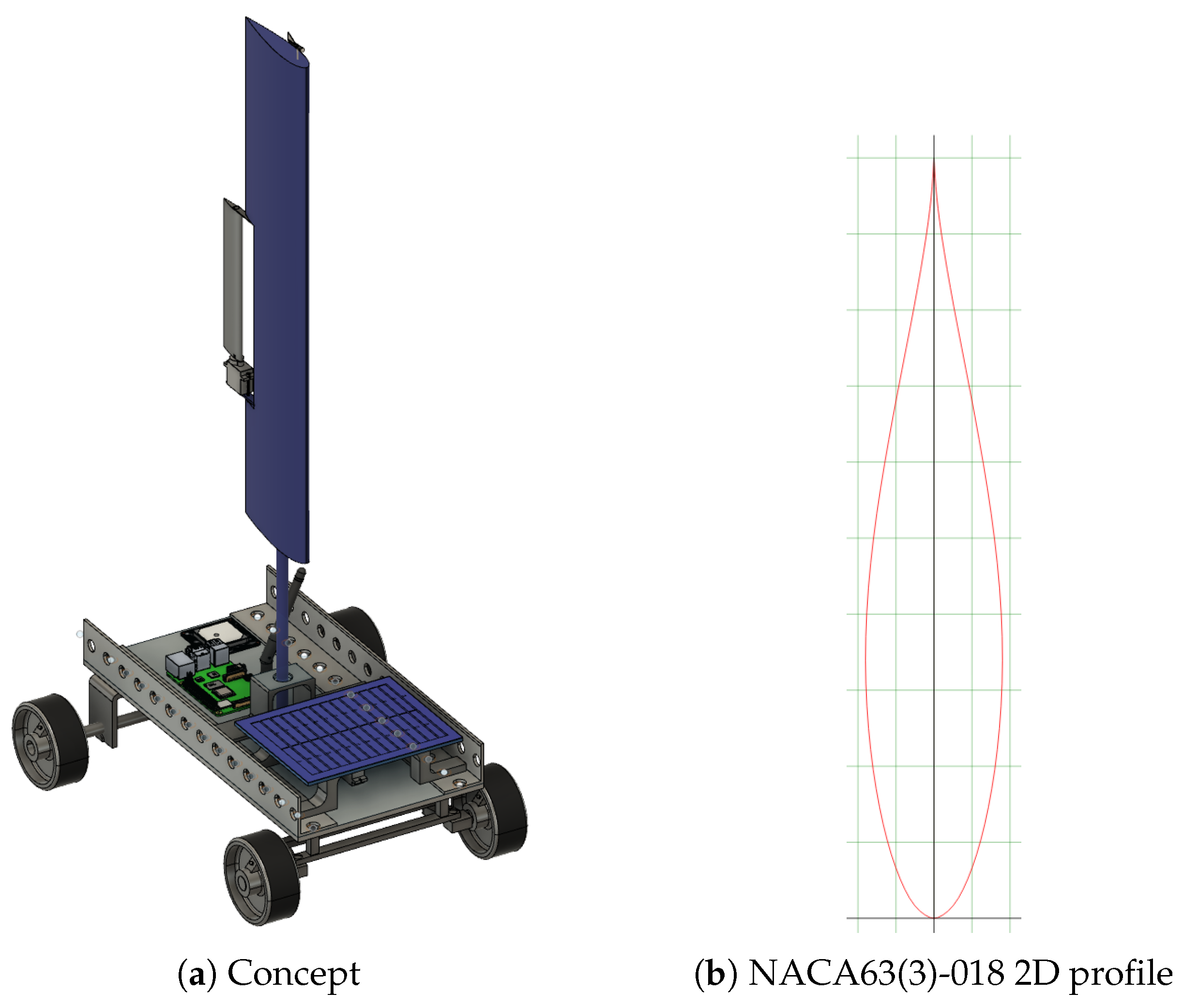
2.1. Platform Design
2.2. Wing Sail Design
2.3. Platform Simulation
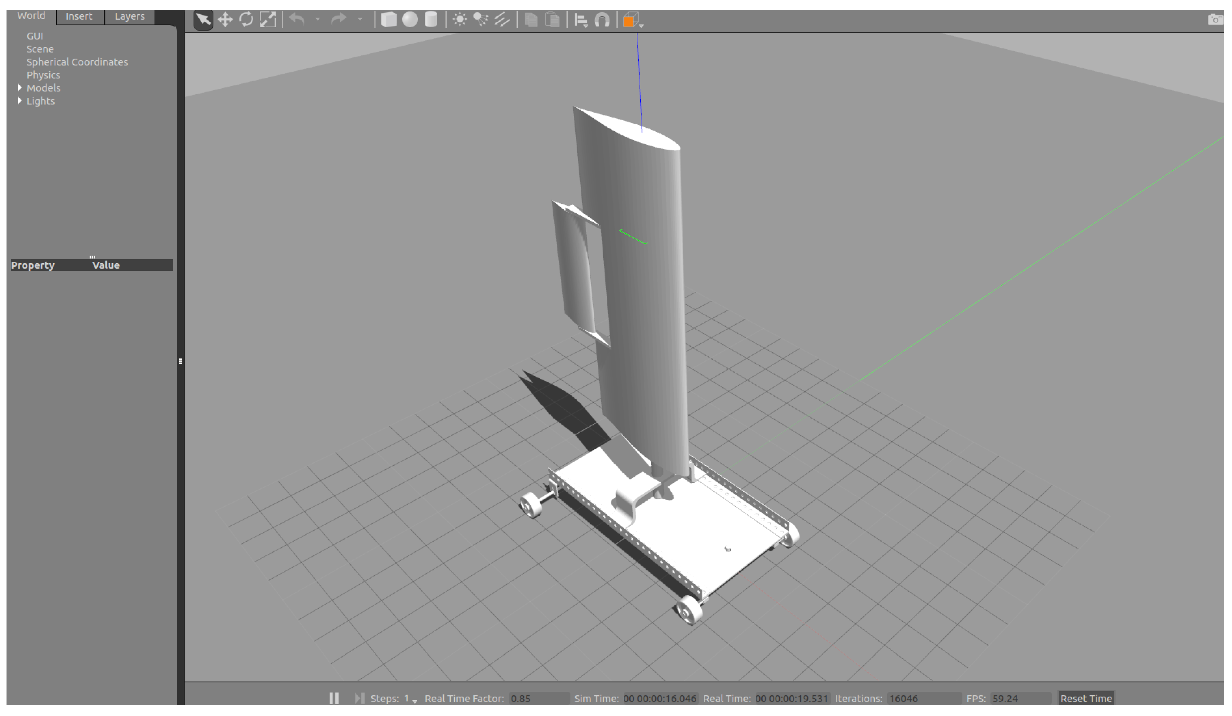
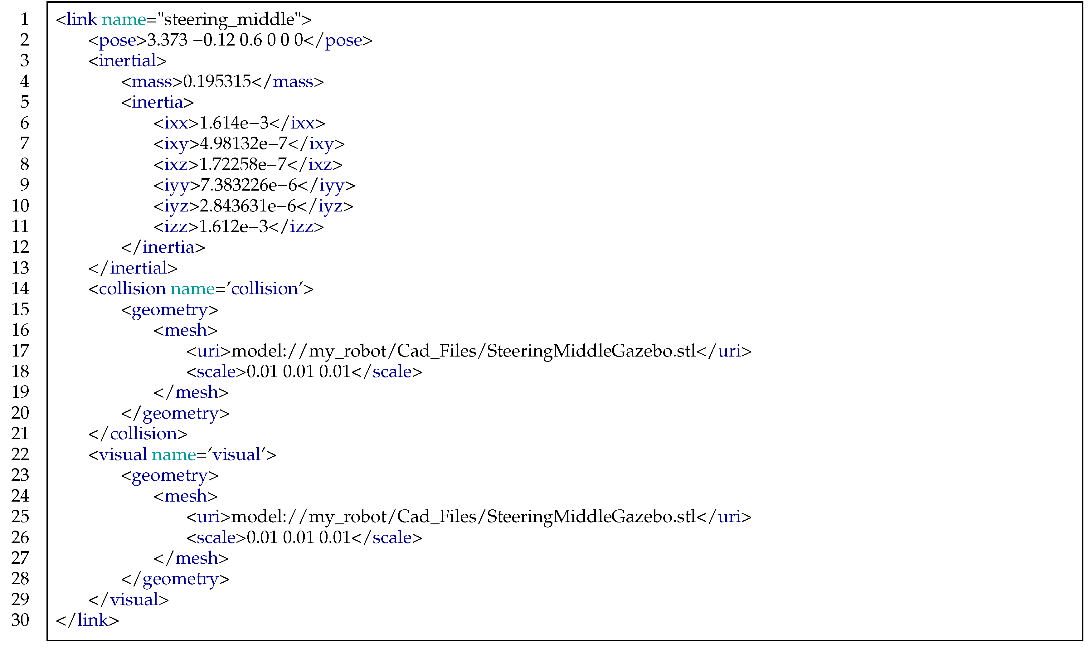
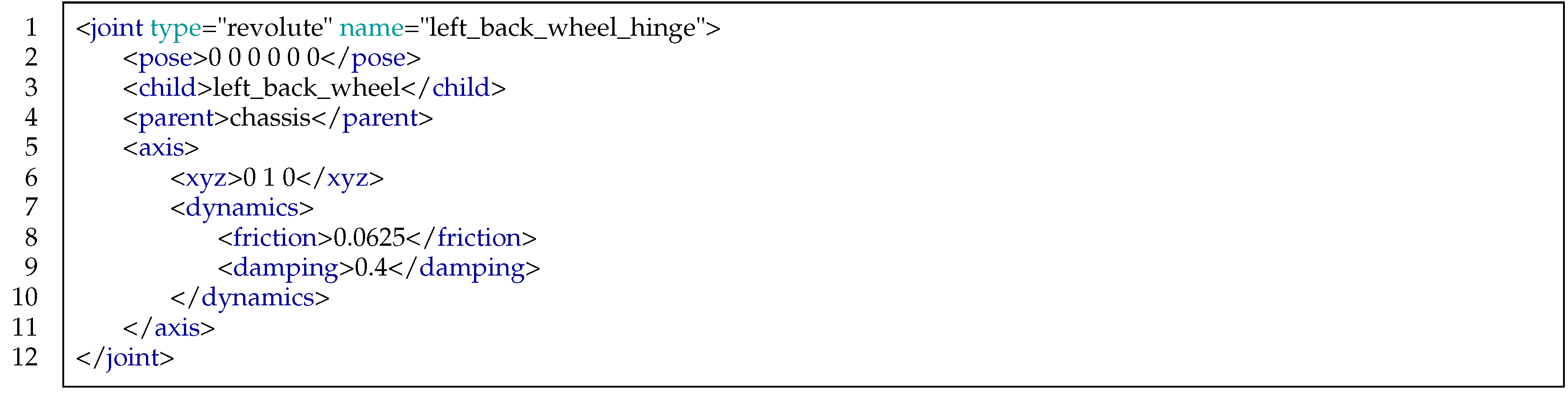
2.3.1. 3D Model


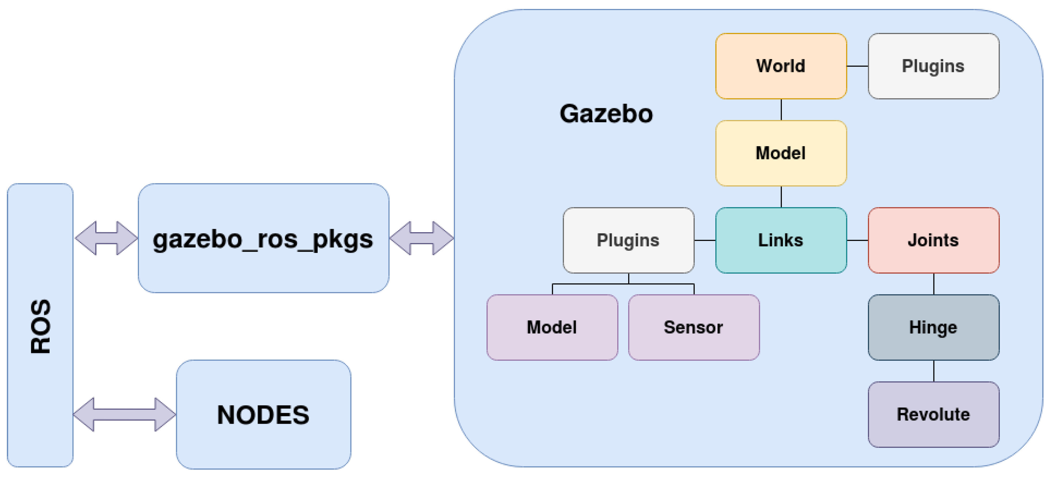
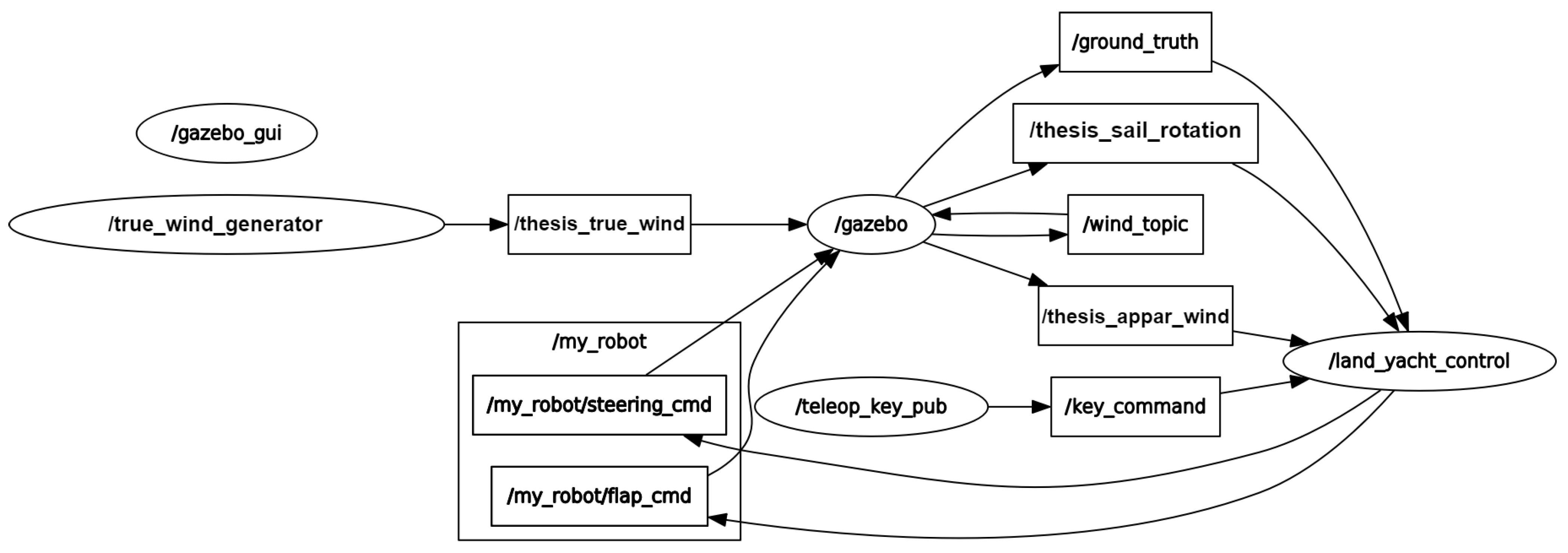
2.3.2. ROS Integration
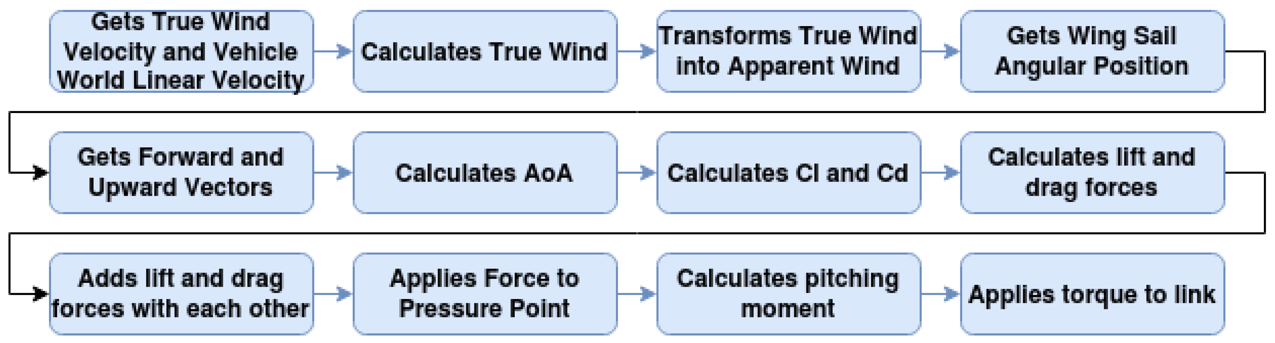
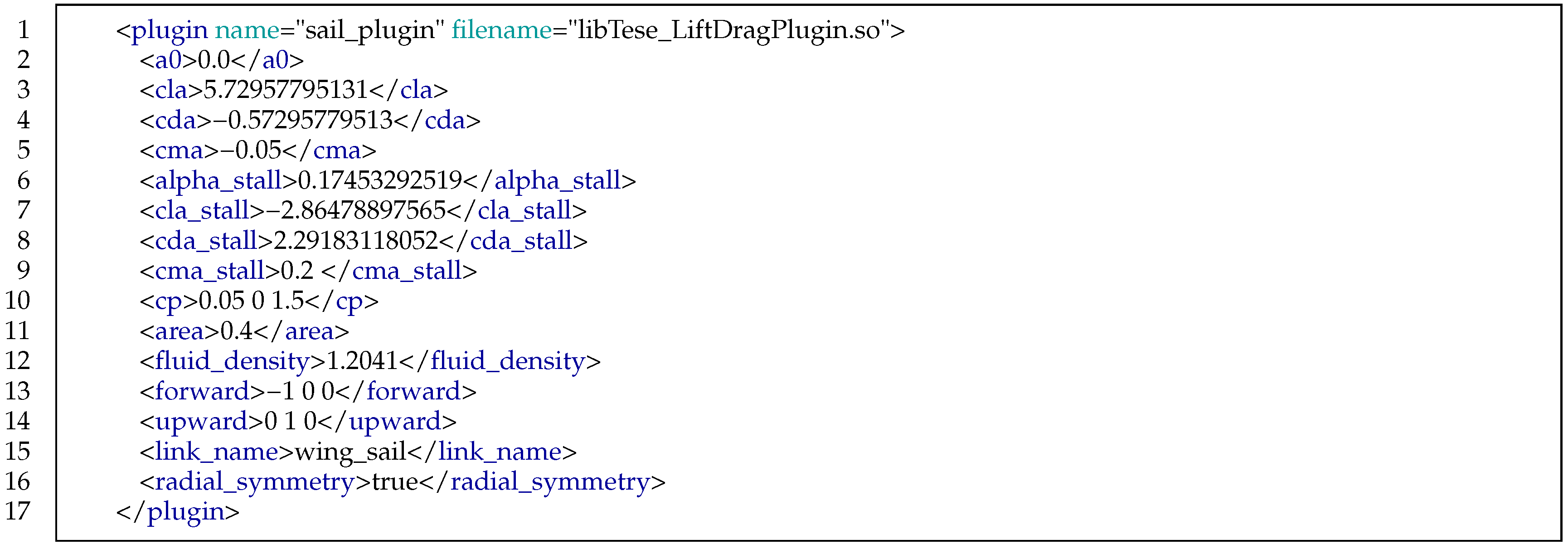
2.3.3. Gazebo Plugins

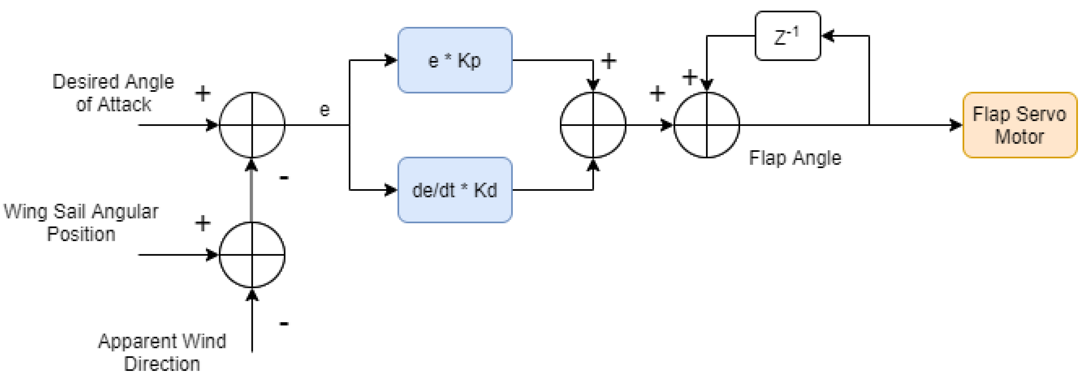
2.3.4. Wing Sail Control
3. Results & Discussion
3.1. Experimental Setup
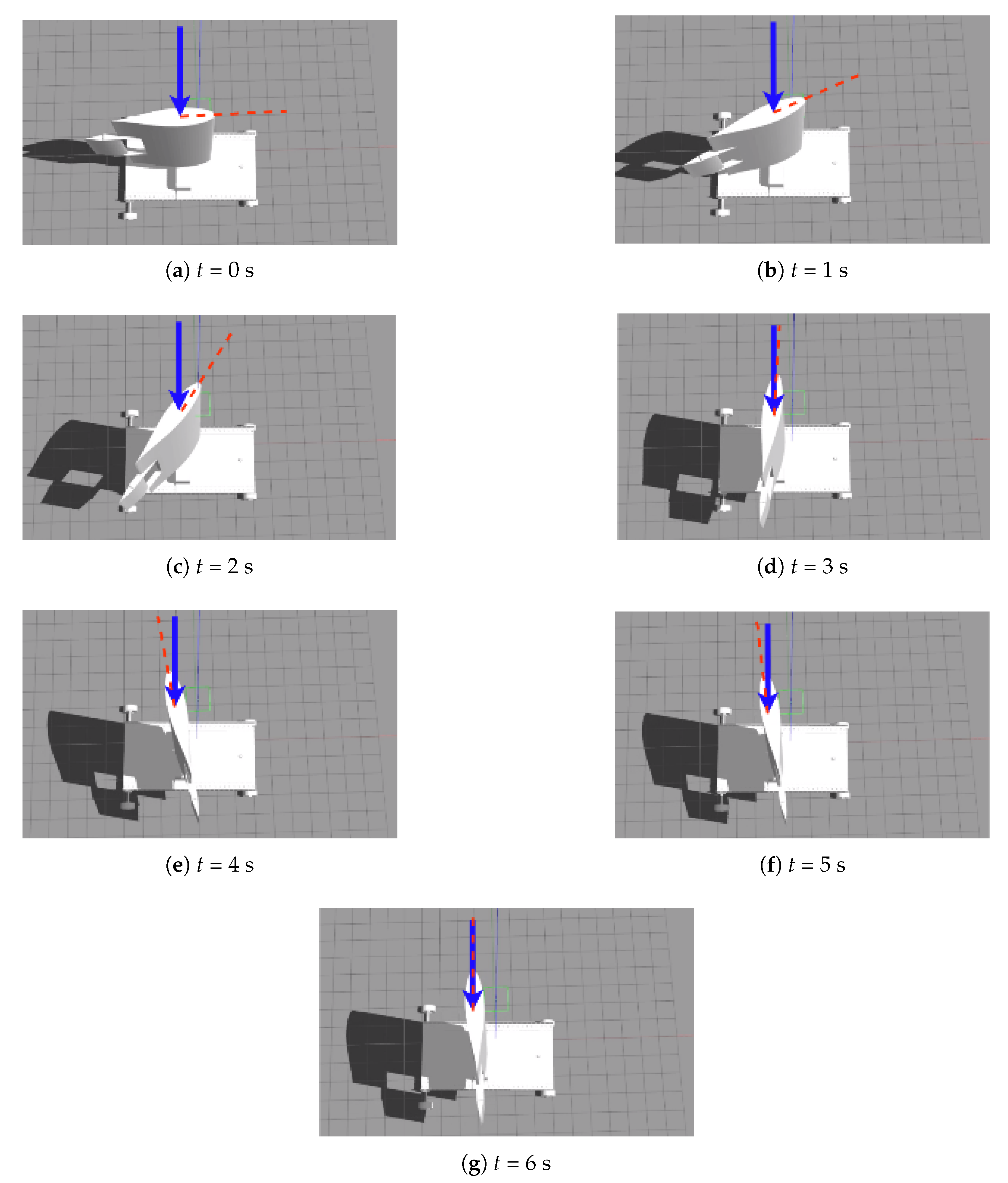
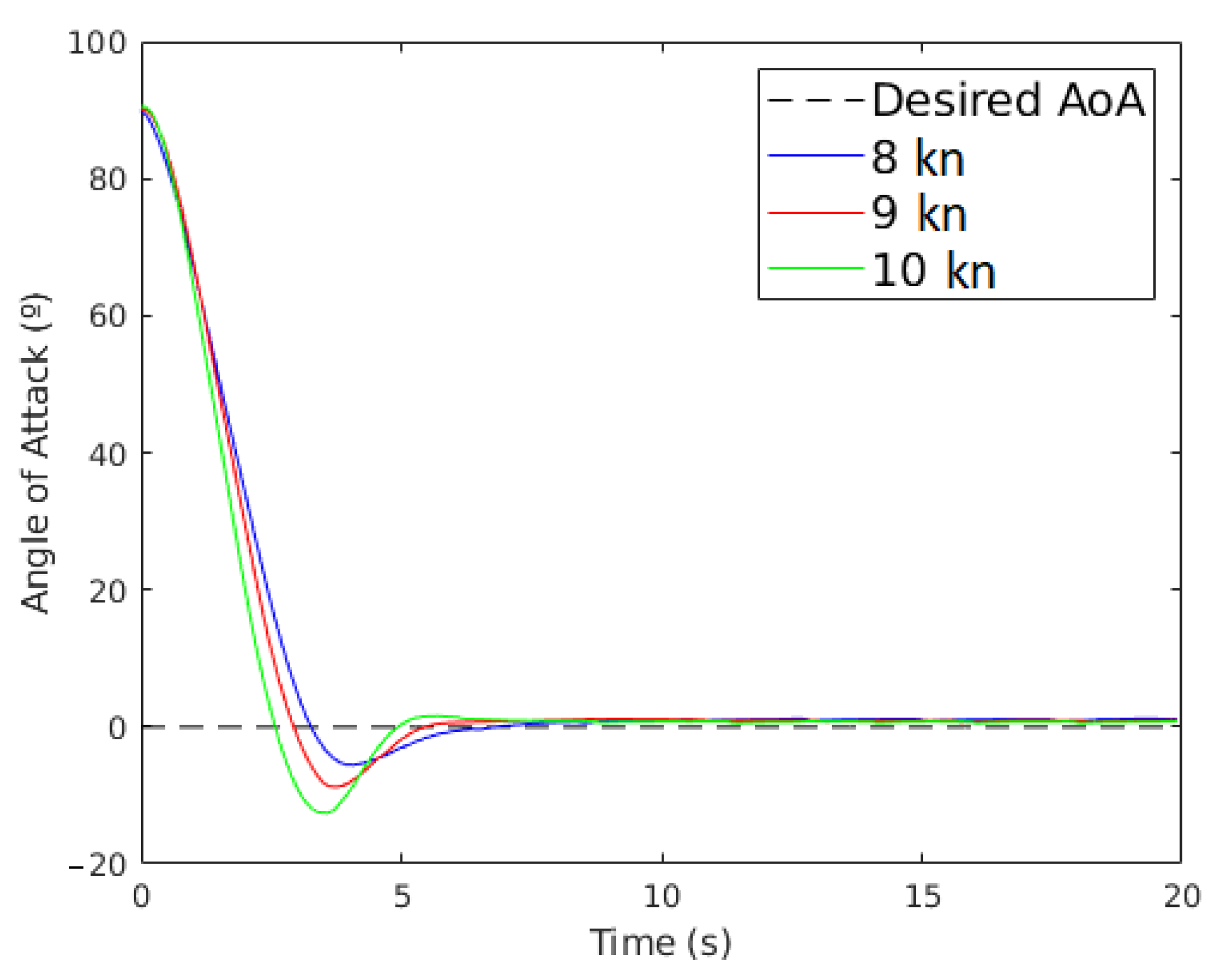
3.2. Wing Sail Alignment to the Wind
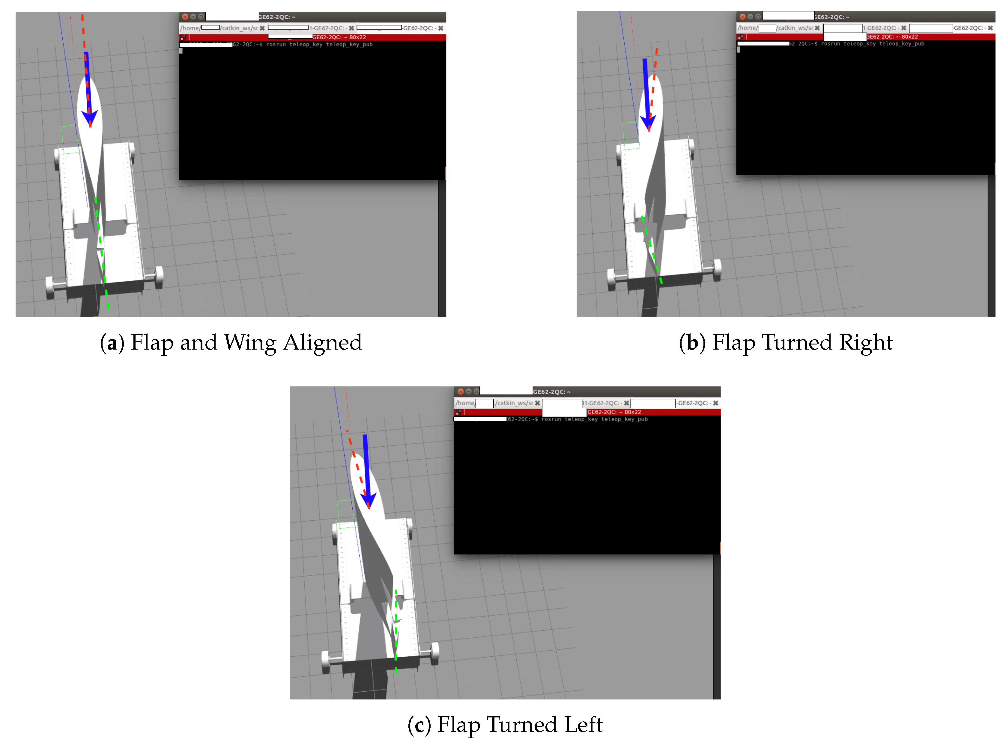
3.3. Wing Sail Response to the Flap Angle
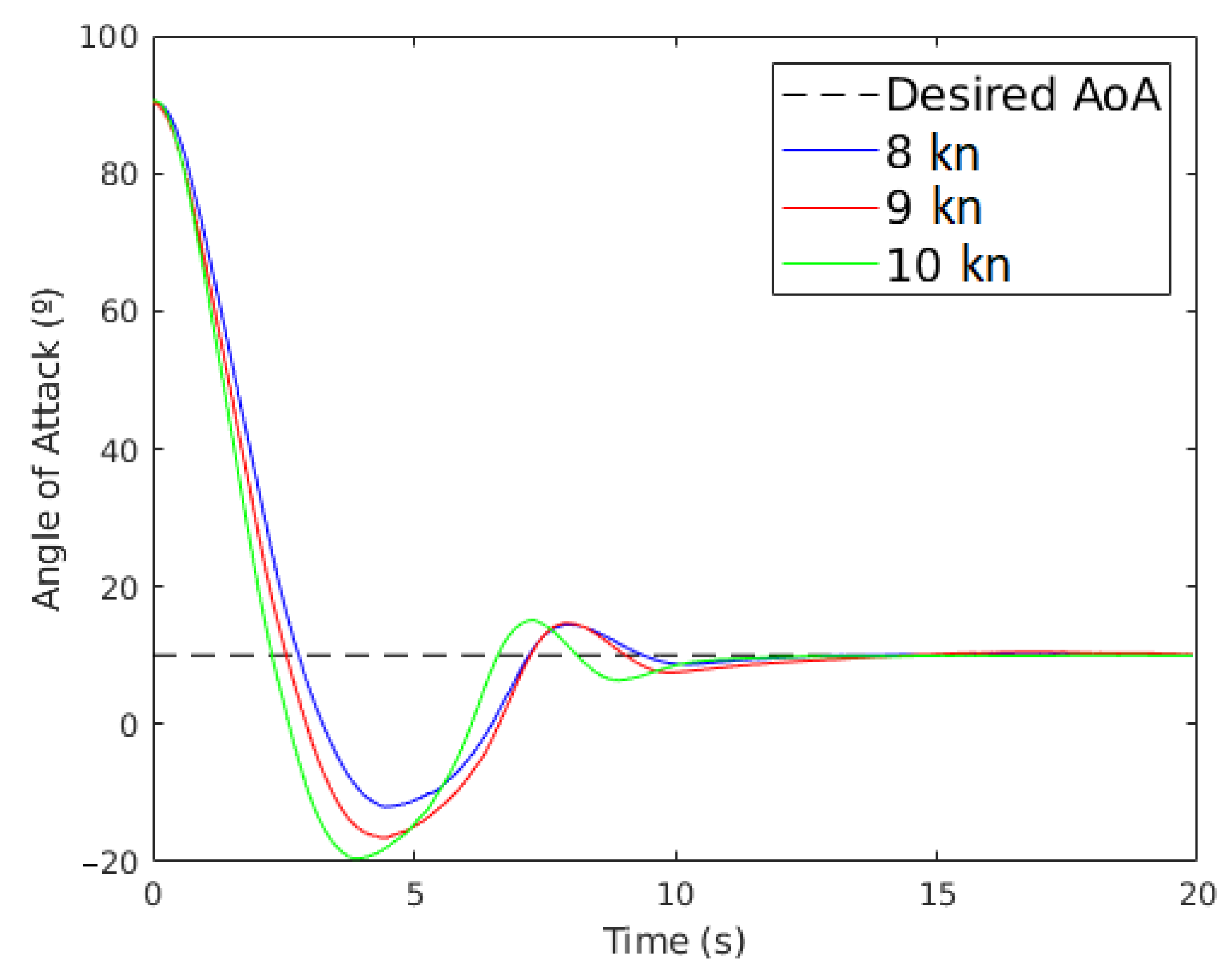
3.4. Setting the Wing Sail to an Angle of Attack
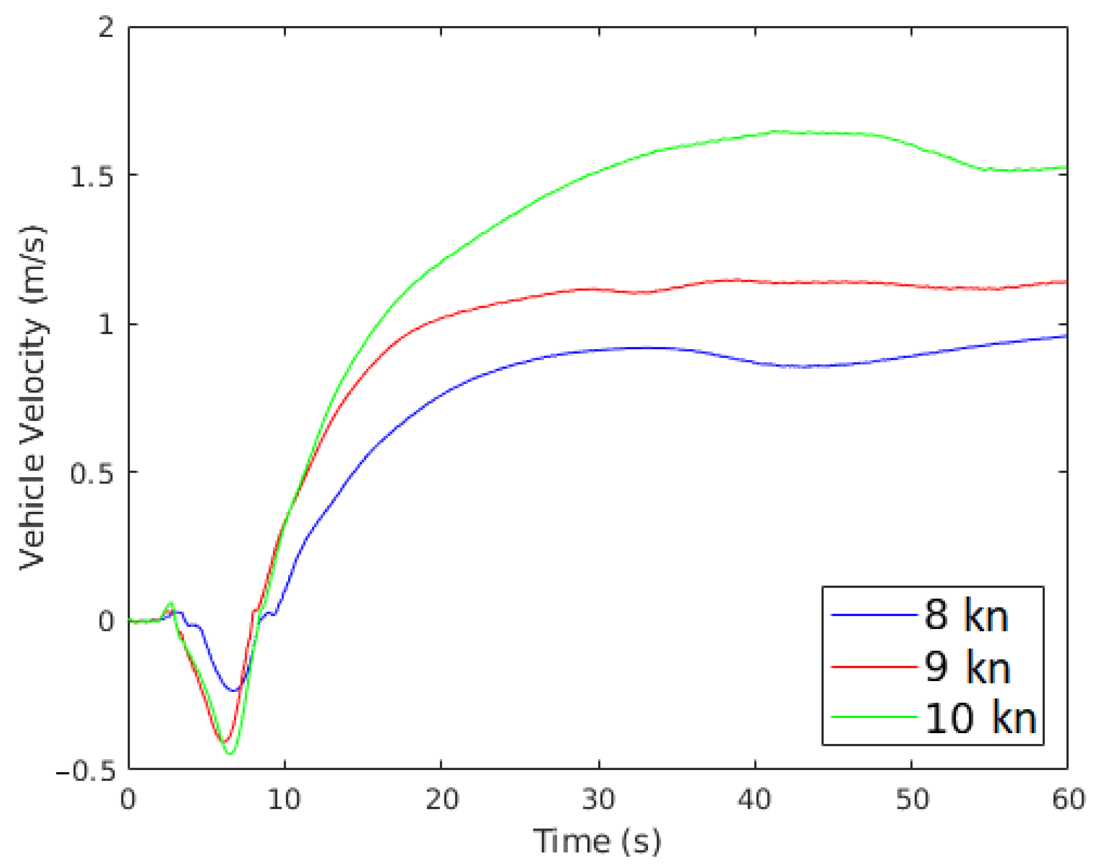
3.5. Vehicle Motion
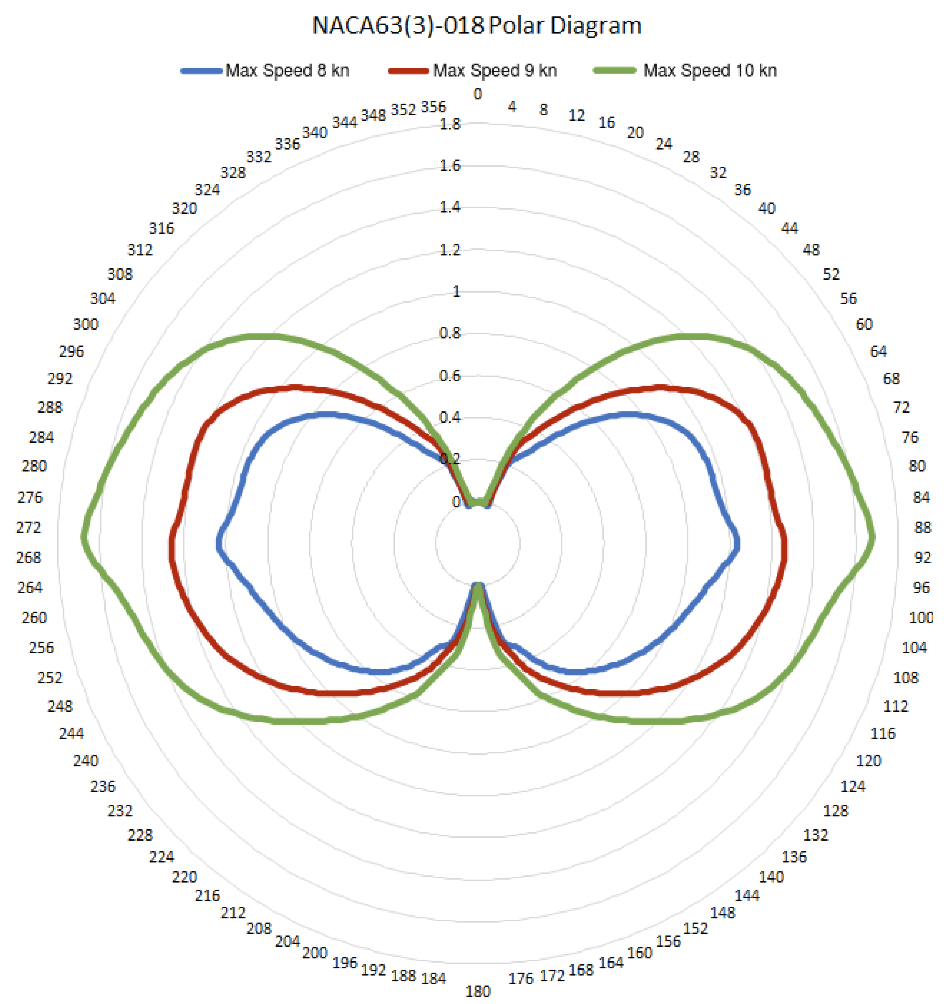
3.6. Polar Diagram
4. Conclusions
Author Contributions
Funding
Institutional Review Board Statement
Informed Consent Statement
Data Availability Statement
Conflicts of Interest
Abbreviations
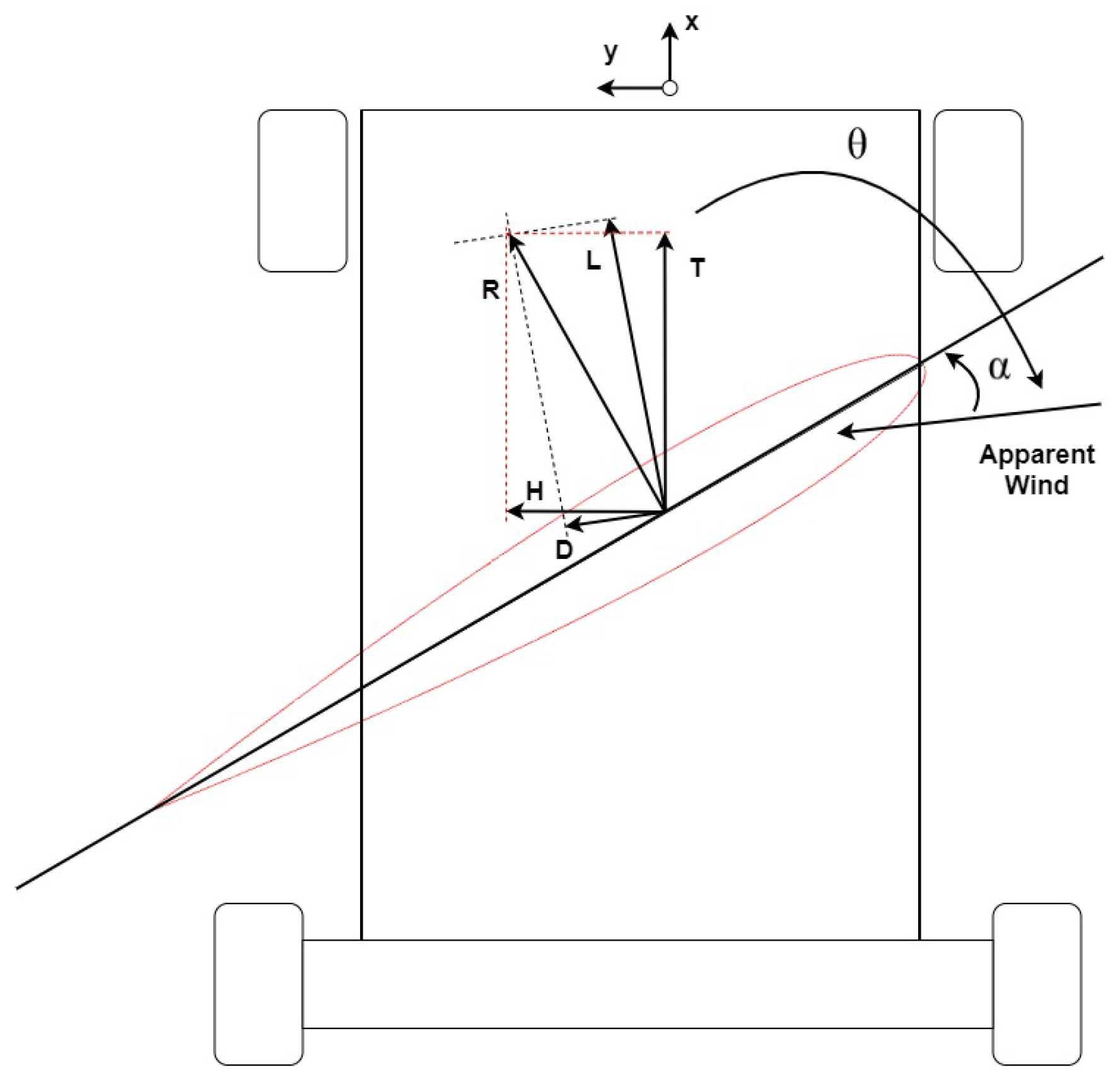
| Angle of Attack | |
| Initial Angle of Attack | |
| Final Angle of Attack | |
| Angle of the Apparent Wind | |
| AoA | Angle of Attack |
| GNSS | Global Navigation Satellite System |
| NACA | National Advisory Committee for Aeronautics |
| PD | Proportional-Differential |
| ROS | Robot Operating System |
| SDF | Simulation Description Format |
References
- National Academy of Engineering. Autonomy on Land and Sea and in the Air and Space: Proceedings of a Forum; The National Academies Press: Washington, DC, USA, 2018. [Google Scholar] [CrossRef]
- Zhu, X.; Kim, Y.; Minor, M.A.; Qiu, C. Autonomous Mobile Robots in Unknown Outdoor Environments; CRC Press: Boca Raton, FL, USA, 2020. [Google Scholar]
- Springer, P.J. Outsourcing War to Machines—The Military Robotics Revolution; Praeger Security International: Santa Barbara, CA, USA, 2018. [Google Scholar]
- Kimball, J. Physics of Sailing; CRC Press: Boca Raton, FL, USA, 2009. [Google Scholar]
- Miller, P.H.; Hamlet, M.; Rossman, J. Continuous Improvements to USNA SailBots for Inshore Racing and Offshore Voyaging. In Robotic Sailing 2012—Proceedings of the 5th International Robotic Sailing Conference; Springer: Berlin/Heidelberg, Germany, 2012; pp. 49–60. [Google Scholar] [CrossRef]
- Anthierens, C.; Pauly, E.; Jeay, F. MARIUS: A Sailbot for Sea-Sailing. In Robotic Sailing 2013—Proceedings of the 6th International Robotic Sailing Conference; Springer: Berlin/Heidelberg, Germany, 2013; pp. 3–12. [Google Scholar] [CrossRef]
- Miller, P.; Sauzé, C.; Neal, M. Development of ARRTOO: A Long-Endurance, Hybrid-Powered, Oceanographic Research Vessel. In Robotic Sailing 2013—Proceedings of the 6th International Robotic Sailing Conference; Springer: Berlin/Heidelberg, Germany, 2013; pp. 53–65. [Google Scholar] [CrossRef]
- Silva, M.F.; Friebe, A.; Malheiro, B.; Guedes, P.; Ferreira, P.; Waller, M. Rigid wing sailboats: A state of the art survey. Ocean. Eng. 2019, 187, 106–150. [Google Scholar] [CrossRef]
- Shukla, P.C.; Ghosh, K. Revival of the Modern Wing Sails for the Propulsion of Commercial Ships. Int. J. Phys. Math. Sci. 2009, 3, 207–212. [Google Scholar]
- Landis, G.; Oleson, S.; Grantier, D.; Balkanyi, L.; Bur, M.; Burke, L.; Bury, K.; Colozza, A.; Dankanich, J.; Drexler, J.; et al. NIAC Phase 1 Final Report: Venus Landsailer Zephyr; Technical Report; NASA: Washington, DC, USA, 2014. [Google Scholar]
- Xie, S.; Chen, J.; li, H.; Luo, J.; Pu, H.; Peng, Y. The research on wing sail of a land-yacht robot. Adv. Mech. Eng. 2015, 7, 1–19. [Google Scholar] [CrossRef]
- Xie, S.; Feng, K.; Peng, Y.; Luo, J.; Chen, J.; Gu, J. Design and analysis of an autonomous controlled four wheeled land yacht. In Proceedings of the 2014 IEEE International Conference on Information and Automation, ICIA 2014, Hailar, China, 28–30 July 2014; pp. 773–778. [Google Scholar] [CrossRef]
- Zhu, A.; Beer, C.; Juhandi, K.; Orlov, M.; Bacau, N.; Kádár, L.; Duarte, A.J.; Malheiro, B.; Justo, J.; Silva, M.F.; et al. Sail Car—An EPS©ISEP 2019 Project. In Proceedings of the 2020 IEEE Global Engineering Education Conference (EDUCON), Porto, Portugal, 27–30 April 2020; pp. 487–492. [Google Scholar] [CrossRef]
- Landis, G.A.; Oleson, S.R.; Grantier, D. Zephyr: A Landsailing Rover for Venus. In Proceedings of the 65th International Astronautical Congress, Toronto, QC, Canada, 29 September 2014; p. 14. [Google Scholar]
- Chen, J.; Ye, Z.; Yang, R.; Cai, G.; Li, J.; Li, H. Design and Control of Multiple Wing-sail Land Yacht Robot. In Proceedings of the 2018 IEEE International Conference on Mechatronics and Automation (ICMA), Changchun, China, 5–8 August 2018; pp. 1800–1805. [Google Scholar] [CrossRef]
- Mirzaei, P.A.; Rad, M. Toward design and fabrication of wind-driven vehicles: Procedure to optimize the threshold of driving forces. Appl. Math. Model. 2013, 37, 50–61. [Google Scholar] [CrossRef]
- Dong, Y.; Ding, X.; Li, Z.; Zhang, L.; Liu, H.; Ding, N.; Sun, Z.; Qian, H. Wing Sail Land-yacht Modeling And System Verification. In Proceedings of the 2019 IEEE International Conference on Robotics and Biomimetics (ROBIO), Dali, China, 6–8 December 2019; pp. 1350–1355. [Google Scholar] [CrossRef]
- Reina, G.; Foglia, M. Modelling and handling dynamics of a wind-driven vehicle. Veh. Syst. Dyn. 2019, 57, 697–720. [Google Scholar] [CrossRef]
- Larsson, L.; Eliasson, R.; Orych, M. Principles of Yacht Design; Bloomsbury Publishing: London, UK, 2014. [Google Scholar]
- Elkaim, G. Autonomous Surface Vehicle Free-Rotating Wingsail Section Design and Configuration Analysis. J. Aircr. 2008, 45, 1835–1852. [Google Scholar] [CrossRef][Green Version]
- Neal, M. A Hardware Proof of Concept of a Sailing Robot for Ocean Observation. IEEE J. Ocean. Eng. 2006, 31, 462–469. [Google Scholar] [CrossRef]
- Friebe, A.; Olsson, M.; Le Gallic, M.; Springett, J.L.; Dahl, K.; Waller, M. A marine research ASV utilizing wind and solar power. In Proceedings of the OCEANS 2017—Aberdeen, Hong Kong, China, 19–22 June 2017; pp. 1–7. [Google Scholar] [CrossRef]
- Chen, J.; Xie, S.; Luo, J.; Li, H. Wind-driven land-yacht robot mathematical modeling and verification. Ind. Robot 2016, 43, 77–90. [Google Scholar] [CrossRef]
- Rynne, P.F.; von Ellenrieder, K.D. Development and Preliminary Experimental Validation of a Wind- and Solar-Powered Autonomous Surface Vehicle. IEEE J. Ocean. Eng. 2010, 35, 971–983. [Google Scholar] [CrossRef]
- Enqvist, T.; Friebe, A.; Haug, F. Free Rotating Wingsail Arrangement for Åland Sailing Robots. In Robotic Sailing 2016; Alves, J.C., Cruz, N.A., Eds.; Springer: Cham, Switzerland, 2017; pp. 3–18. [Google Scholar] [CrossRef]
- Augenstein, T.; Singh, A.; Miller, J.; Pomerenk, A.; Dean, A.; Ruina, A. Using a Controlled Sail and Tail to Steer an Autonomous Sailboat. In Robotic Sailing 2016; Alves, J.C., Cruz, N.A., Eds.; Springer: Cham, Switzerland, 2017; pp. 91–103. [Google Scholar] [CrossRef]
- Setiawan, J.D.; Chrismianto, D.; Ariyanto, M.; Sportyawan, C.W.; Widyantara, R.D.; Alimi, S. Development of Dynamic Model of Autonomous Sailboat for Simulation and Control. In Proceedings of the 2020 7th International Conference on Information Technology, Computer, and Electrical Engineering (ICITACEE), Semarang, Indonesia, 24–25 September 2020; pp. 52–57. [Google Scholar] [CrossRef]
- Tinoco, V. Modelling and Simulation of a Wing Sail Land Yacht. Master’s Thesis, School of Engineering, Polytechnic of Porto, Porto, Portugal, 2020. [Google Scholar]
- Silva, M.F.; Malheiro, B.; Guedes, P.; Ferreira, P. Airfoil Selection and Wingsail Design for an Autonomous Sailboat. In Robot 2019: Fourth Iberian Robotics Conference; Silva, M.F., Lima, J.L., Reis, L.P., Sanfeliu, A., Tardioli, D., Eds.; Springer: Cham, Switzerland, 2020; pp. 305–316. [Google Scholar] [CrossRef]
- Getzan, G.D.; Shimada, M.; Shimoyama, I.; Matsumoto, Y.; Miura, H. Aerodynamic behavior of microstructures. In Proceedings of the ETFA ’94. 1994 IEEE Symposium on Emerging Technologies and Factory Automation. (SEIKEN) Symposium-Novel Disciplines for the Next Century—Proceedings, Tokyo, Japan, 6–10 November 1994; pp. 54–61. [Google Scholar] [CrossRef]
- Airfoil Tools. NACA 63(3)-018 (naca633018-il). Available online: http://airfoiltools.com/airfoil/details?airfoil=naca633018-il (accessed on 28 November 2020).
- Drela, M. XFOIL: An Analysis and Design System for Low Reynolds Number Airfoils. In Low Reynolds Number Aerodynamics; Mueller, T.J., Ed.; Springer: Berlin/Heidelberg, Germany, 1989; pp. 1–12. [Google Scholar]
- Rivera, Z.B.; Simone, M.C.D.; Guida, D. Unmanned Ground Vehicle Modelling in Gazebo/ROS-Based Environment. Machines 2019, 7, 42. [Google Scholar] [CrossRef]


| Source | Wing Sail | Chassis | |||||||
|---|---|---|---|---|---|---|---|---|---|
| Airfoil | Free Rot. | Angle Range | Wingspan | Lat. Area | Mass | Material | Wheels | Mass | |
| (°) | (m) | (m2) | (kg) | (kg) | |||||
| Xie et al. [11] | NACA0018 | No | 0–360 | 1 | Aluminum | 4 | 19 | ||
| Chen et al. [15] | 3 × NACA0018 | No | 0–360 | 3 × 1 | 3 × 0.25 | 3 × 2.15 | Aluminum | 4 | 19 |
| Zhu et al. [13] | NACA0015 | Yes | 0–360 | - | Steel | 4 | - | ||
| Mirzaei et al. [16] | NACA0012 | No | - | 1 | - | - | 3 | 8 | |
| Dong et al. [17] | NACA0015 | No | 0–270 | - | Steel & Plastic | 4 | - | ||
| Reina et al. [18] | NACA0012 | No | - | 3 | - | - | 3 | 100 | |
| Geoffrey et al. [10] | NACA0015 | No | - | 12 | 49 | - | 3 | 35 | |
Publisher’s Note: MDPI stays neutral with regard to jurisdictional claims in published maps and institutional affiliations. |
© 2021 by the authors. Licensee MDPI, Basel, Switzerland. This article is an open access article distributed under the terms and conditions of the Creative Commons Attribution (CC BY) license (http://creativecommons.org/licenses/by/4.0/).
Share and Cite
Tinoco, V.; Malheiro, B.; Silva, M.F. Design, Modeling, and Simulation of a Wing Sail Land Yacht. Appl. Sci. 2021, 11, 2760. https://doi.org/10.3390/app11062760
Tinoco V, Malheiro B, Silva MF. Design, Modeling, and Simulation of a Wing Sail Land Yacht. Applied Sciences. 2021; 11(6):2760. https://doi.org/10.3390/app11062760
Chicago/Turabian StyleTinoco, Vítor, Benedita Malheiro, and Manuel F. Silva. 2021. "Design, Modeling, and Simulation of a Wing Sail Land Yacht" Applied Sciences 11, no. 6: 2760. https://doi.org/10.3390/app11062760
APA StyleTinoco, V., Malheiro, B., & Silva, M. F. (2021). Design, Modeling, and Simulation of a Wing Sail Land Yacht. Applied Sciences, 11(6), 2760. https://doi.org/10.3390/app11062760