Article

Fire Safety Risk Analysis of Conventional Submarines

1
BMT Defence and Security Australia, 99 King Street, Melbourne, Victoria 3000, Australia
2
DST Group, 506 Lorimer Street, Fishermans Bend, Melbourne, Victoria 3207, Australia
3
Institute for Sustainable Industries and Liveable Cities, Victoria University, Melbourne, Victoria 3030, Australia
*
Author to whom correspondence should be addressed.
Current affiliation: BAE Systems Australia, Edinburgh 5111, Australia.
Appl. Sci. 2021, 11(6), 2631; https://doi.org/10.3390/app11062631
Submission received: 6 January 2021 / Revised: 10 March 2021 / Accepted: 11 March 2021 / Published: 16 March 2021
(This article belongs to the Special Issue Advanced Analysis and Technology in Fire Science and Engineering)

Abstract

:
Conventional (diesel-electric) submarines can provide improved stealth compared to nuclear submarines once submerged. This is because nuclear submarines are generally larger and are required to operate their nuclear reactors at all times, unlike diesel-electric submarines which are generally smaller and can run exclusively on batteries when submerged which generally requires fewer moving parts. These characteristics normally result in a smaller acoustic, thermal and magnetic signature which afford diesel-electric submarines greater stealth when submerged. However, the current underwater range and endurance is limited by the energy storage or generation for submerged operation. The application of emerging energy storage technology seeks to address this limitation and provide significant tactical and operational advantages to the conventional submarine operator. From a fire safety perspective, the potential addition of technologies such as rechargeable lithium-ion batteries, Air Independent Propulsion (AIP) systems and increasingly sophisticated electronic equipment dramatically changes the risk space in an already challenging and unforgiving underwater environment. This study reviews the functions, failure modes and maturity of emerging technologies that have serious submarine fire safety implications. A semi-quantitative assessment of the fire risk associated with potential large future conventional submarine design options for batteries and AIP is provided. This assessment concludes that lithium-ion batteries pose the greatest challenge with regard to integration into conventional submarines without compromising reliability or safety.

1. Introduction

Fire dynamics are well understood in many industries, including the maritime industry, where various regulations, guidelines, technologies and engineering expertise have served to reduce the risk associated with fires. Fire incidents on submarines present unique challenges, however, and continue to pose a serious risk to submarine operations and submariners. The UK Ministry of Defence (MoD) reported 266 fire incidents on its nuclear submarines in the last 25 years, 20 of which required significant on-board resources to contain [1]. In a space of five years between 2011 and 2015, the Indian Navy have suffered four serious fire or fire safety system related incidents on their conventional submarines, claiming a total of 41 lives [2,3,4].
The current geo-political and maritime security environment dictate that conventional, diesel-electric submarines are still a popular choice for many nations such as Australia. Conventional submarines can provide improved stealth compared to nuclear submarines once submerged. Submarines may be required to travel large distances and avoid detection to maintain security of national interests such as shipping lanes. This requires long underwater range and endurance which is currently generally provided by lead-acid battery storage that, when depleted, require submarines to surface to charge with diesel generators. During battery charging there is a greater likelihood of a submarine being detected. Emerging energy generation and storage technologies have the potential to significantly increase energy supply for underwater operation for the conventional, diesel-electric design. As new submarine designs emerge, they are likely to feature some emerging energy generation and storage technologies in the manned submarine domain. From the application of these technologies, fire risks previously not considered in submarine design and operation will be encountered which will necessitate research, development, testing and evaluation of potential controls. The primary purpose of this study is to review a range of possible technologies that may be integrated into the future submarines and provide a risk-based assessment of fire safety and mitigation options.
The paper consists of various sections starting with a methodology which also outlines the limitations of this study. An overview of systems/technologies and risks are described from a historical perspective, including available mitigation measures. Then, the fire safety risk is considered for various potential technologies including future submarine context, functional description, fuel and ignition source and technology maturity. It is followed by a semi-quantitative fire risk assessment and suggestions for potential mitigation measure. The concluding section summarizes the findings and proposes future works.

2. Methodology

The study will review and assess the fire risk associated with potential future submarine design options for fire safety critical elements including batteries, Air Independent Propulsion (AIP), electrical wiring and electronic systems. Three AIP technologies generally used in submarines are: hydrogen fuel cell, MESMA (Module Energie Sous-Marin Autonome) engines and Stirling engines. The study will also include a brief overview of potential fire safety system components including the latest fire safety technology (e.g., water mist, hypoxic fire prevention systems, new materials, etc.). The risk-based assessments will involve understanding of fire scenarios, possible consequences based on past incidence and a semi-quantitative risk analysis. Key outputs from the study will be focused on highlighting key fire risk areas in future submarine design and providing an indication of the suitability and effectiveness of available technologies.

Limitations

The risk assessment will exclude fire caused by combat incidents involving the submarine, although this should be considered for further research to assist in the assessment of platform survivability. Submarine armament and weaponry has been excluded from the study due to the classified nature of emerging technologies and the relatively high level of fire safety understanding surrounding the storage, handling and use of weaponry. Furthermore, only the submerged mode of submarine operation, which refers to operation at or below periscope depth, will be considered. Not only is this the most safety critical mode of operation for a submarine, but it is also the mode in which the technologies under consideration primarily operate. Notwithstanding, a holistic approach is required to manage risk across the entire lifecycle of the submarine including other modes of operation, maintenance and disposal, however the scope of research in this instance was necessarily constrained and focused on the most severe risks so as to target more valuable research outcomes first. Noting the way in which these technologies will be used, and that submerged operation presents the highest risk, any controls developed to reduce risk in this operational mode will significantly benefit other modes of operation.

3. Overview of Systems and Risks

3.1. General Objectives of Submarine Mission and Hazards

The key submarine mission objectives in the event of a fire are assumed to be (a) Prevent the loss of the submarine; (b) Prevent loss of life and minimise injury where possible; and (c) Maintain stealth and continue mission if possible [5]. However, anecdotal evidence suggested that sometimes the mission (c) gets priority over the crew (b). Note that the order of priority is dependent on the mission and the phase of the mission when the incident occurs which can sometimes mean mission is prioritised above the safety of the crew. The objectives typically require damage control and emergency operating procedures to be enacted to extinguish the fire, restore functionality to the submarine, tend to crew members, retain stealth if at all possible and once the situation is settled, decide to continue the mission or return to base.
The consequences of fire on a submarine can lead directly to injury and loss of life, however due to the hostile, high-pressure, underwater environment in which a submarine operates, a fire can lead indirectly to loss of the submarine even if the fire is able to be contained. Examples include:
  • Fire damage to the propulsion system or supporting subsystems which compromises propulsion of the submarine, leading to depth excursion, resulting in loss of the submarine.
  • Fire and smoke damage causing multiple system failure and compromised ability to monitor and control the submarine, resulting in loss of the submarine.
  • Heat from fire reducing the strength of the pressure hull, leading to loss of structural integrity, resulting in loss of the submarine.
  • Fire damage and/or firefighting and damage control actions leading to compromise of fluid containment systems, causing internal flooding of the submarine, resulting in loss of the submarine.
  • Fires resulting from malfunction of weapon systems, torpedoes and missiles.

3.2. Fire Dynamics on Submarines and Possible Consequences

Submarines have a number of unique characteristics that contribute to rapid growth and spread of fire and smoke, the effectiveness of fire suppressants, and occupant behaviour in the event of a fire. Some key physical characteristics, highlighted by the US Naval Ships’ Technical Manual Chapter 555—Volume 2 Submarine Firefighting [6], and other factors are discussed below.
  • Fire Growth and Intensity—Submerged submarines are pressurised and without ventilation, creating ideal conditions for accelerated fire growth and overall higher intensity.
  • Spread of Smoke and Heat—the layout of a submarine places many ignition and fuel sources at the bottom of the submarine whilst access points in many compartments are provided to the decks above which provides ideal conditions and pathways for the spread of rising smoke and heat.
  • Occupant Behaviour—in fire scenarios, occupant characteristics can be wide and varied with some contributing significantly to the outcome of a fire incident. Fortunately, in a submarine all occupants are fit, well trained, intimately familiar with the layout of the submarine and there is always at least a subset of the crew that is highly alert and actively monitoring the health of the submarine.
These characteristics provide both challenges and opportunities to manage fire risks and aspects that are unique to submarines and must be considered carefully in the design and operation of a submarine.

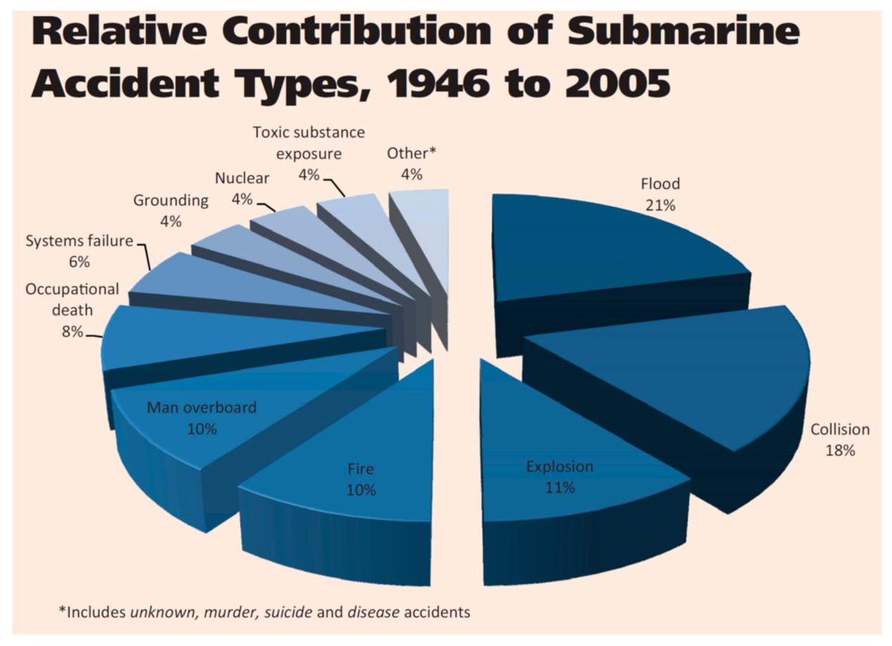
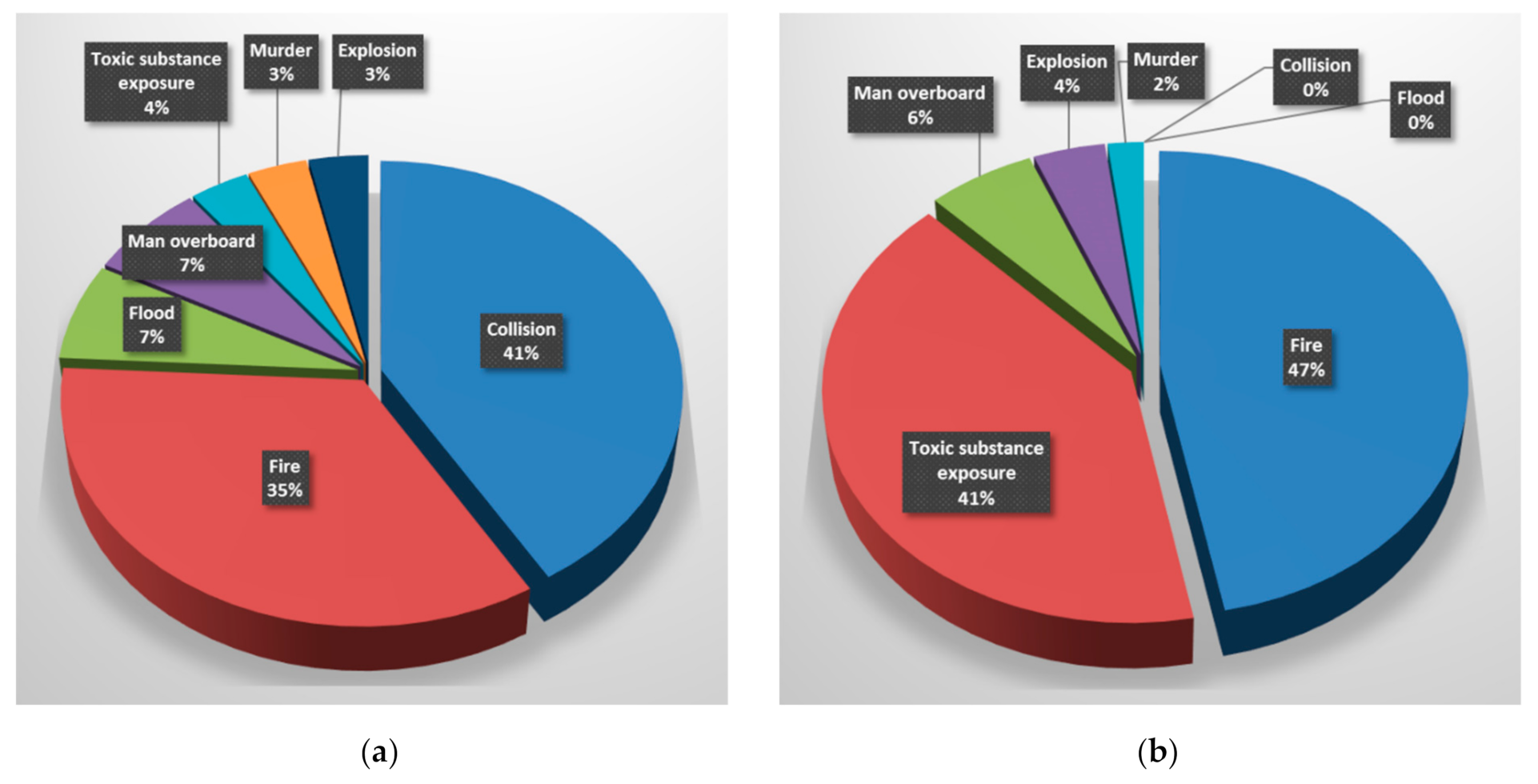
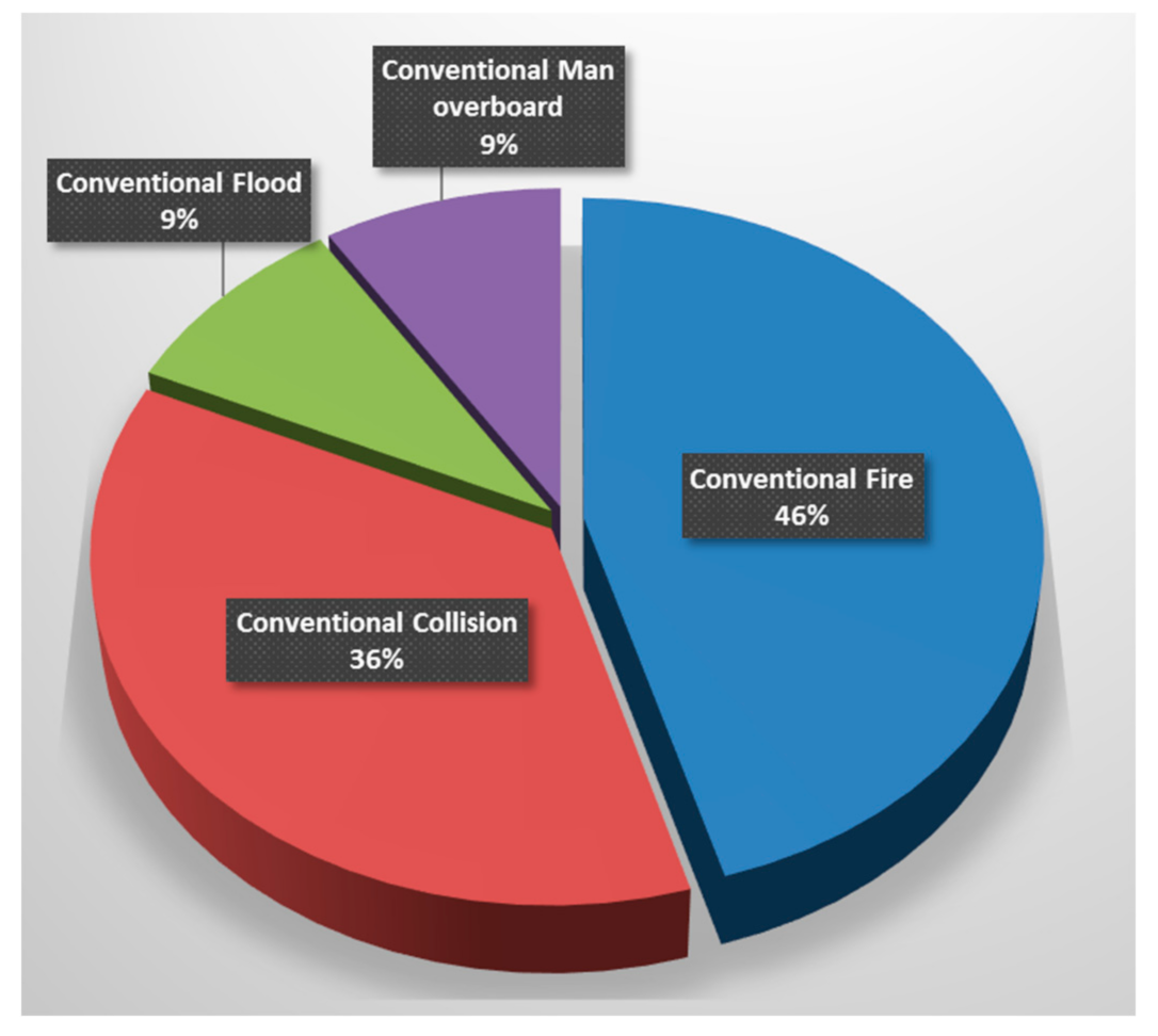
3.3. Safety Incident On-Board Submarines

Fire remains one of the top types of submarine incidents, as shown by a comprehensive statistical review of submarine incidents since 1946 [7]. A breakdown of incident types, summarised in Figure 1, shows that 10% of incidents were fire, and 11% were explosion which can often be attributed to flammable substances and other causes of fire.
It is important to note that submarine technology and operating procedures have changed significantly since 1946, particularly following the inception of the US Navy’s SUBSAFE program following the loss of USS Thresher in 1963. Therefore, it is pertinent to consider submarine incidents in more recent times. A listing of publicly reported submarine incidents from 2006 to 2015 is shown in Table 1.
It should be noted that in many cases, reporting the incidence, nature and severity of submarine incidents is governed by defence security classification and therefore non-disclosure of these events to the public. It is likely that many more submarine incidents have occurred but cannot be revealed or analysed for reasons of national security. Figure 2a summarises an analysis of the incidents in Table 1 and shows that collision and fire remain among the top types of submarine incidents in recent years.
In terms of fatalities, fire was the leading cause of death on-board a submarine from 2006 to 2015, as shown in Figure 2b. Those categorised as ”toxic substance exposure” can be traced back to a single event which was caused by inadvertent triggering of the automatic fire suppression system.
A review of the causes of incidents resulting in fatalities shows that fire in critical submarine components such as batteries, engines and electrical equipment, and fire safety system components, namely automatic suppression systems, account for the vast majority of submarine fatalities in recent years. For the purposes of this study, incidents involving conventional submarines are of particular interest. Incident types for conventional submarines follow much the same trend, as shown in Figure 3.
Based on the case reviewed, fire incidents on submarines appear to have become more prevalent in recent years with flooding incidents becoming less frequent. As stated previously, recent advancements in energy storage and AIP technology will see the integration of new components previously unproven in a submarine which could potentially further increase operational risks related to fire.
The above review of submarine safety incidents highlights the importance of fire safety on submarines.

3.4. Fire Safety Risks for Conventional Submarines

Unlike nuclear submarines which have a relatively boundless air independent power supply, conventional submarines must rely on hydrocarbon fuels and energy storage technologies to achieve stealth and discretion. This presents a unique set of fire safety risks.

3.4.1. Current State—Australia’s Collins Class

Australia’s Collins Class submarine has a traditional diesel-electric, conventional submarine configuration with three diesel engines providing electrical generation for four lead-acid battery packs that provide electrical power for main propulsion power and hotel load. The submarine’s fire safety system features some important components [37]: (1) A halon 1301 fixed fire suppression system; (2) Zone-related smoke, flame and heat detectors; (3) Aqueous Film-Forming Foam (AFFF) system for manual firefighting; and (4) Various portable fire extinguishers.

3.4.2. Future Submarine

For Australia’s future submarine various powering options were considered [38] which is shown in Table 2. With the exception of diesel engines, many of these technologies have seen little to no service in large conventional submarines so the risks for submarines are somewhat unknown.
Fire safety system components for future submarines may include:
  • Prevention: Hypoxic atmosphere fire prevention system, monitoring and control systems;
  • Suppression: Water mist, foam, gaseous agents; and
  • Structure and materials: Fire resistant casing for batteries.

3.4.3. Fire Risk Considerations

A more informed, semi-quantitative risk analysis will be undertaken in the later stages of this project, however a high-level assessment of the abovementioned technologies highlights some key fire risk factors to be considered when assessing suitability and effectiveness of different options:
  • Diesel engines:
The fire risks for diesel engines are well known and there are no new risks that can be foreseen for future submarines. Common causes of fires include hose/pipe leakages, ruptures, and disconnections causing release or spray of flammable fuels and oils onto hot surfaces or other ignition sources.
  • Air Independent Propulsion:
Air Independent Propulsion (AIP) requires the submarine to have its own independent source of air, such as liquefied oxygen, to facilitate the release of energy in order to provide propulsion to the submarine whilst it is submerged. The use of air independent propulsion on submarines dates back to World War II, however newer technologies such as fuel cells and the MESMA steam turbine have only been in use for the last 10–15 years. Further, AIP has had very limited use in large conventional submarines.
AIP requires high pressure storage of oxygen, hydrogen and other flammable gases in the submarine which provides a readily ignitable fuel source for fires. In addition, the operation of AIP machinery in some cases requires the combustion of fuels and exhaust of hot gases which are unable to be vented outside the submarine when operating at depth. A fire incident is significantly harder to manage during submerged operations which is often when use of AIP is required [39].
  • Lithium-ion batteries:
With superior energy density, improved charge and discharge dynamics and better overall operational life, lithium-ion batteries can provide significant underwater endurance and range advantages over the lead-acid batteries which are typically used in conventional submarines [39]. However, lithium-ion batteries present a greater fire risk than lead-acid batteries and the implications of their use in conventional submarines over an extended time period is not well understood relative to lead-acid batteries which have been in operation on submarines for around a century.

4. Fire Safety Risk Considerations—Technology Review

4.1. Lithium-Ion Batteries

4.1.1. Future Submarine Context

Due to the relatively high energy density of lithium-ion batteries, space, weight and power savings can be traded off for greater underwater endurance and range which can greatly increase submarine stealth [5]. Note the traditional diesel-electric submarine design in Figure 4 with two battery compartments, one each at the front and rear of the submarine. Surrounding compartments typically include void and tank spaces and unmanned machinery spaces. Manned machinery, accommodation and munition spaces are typically located on the deck above.

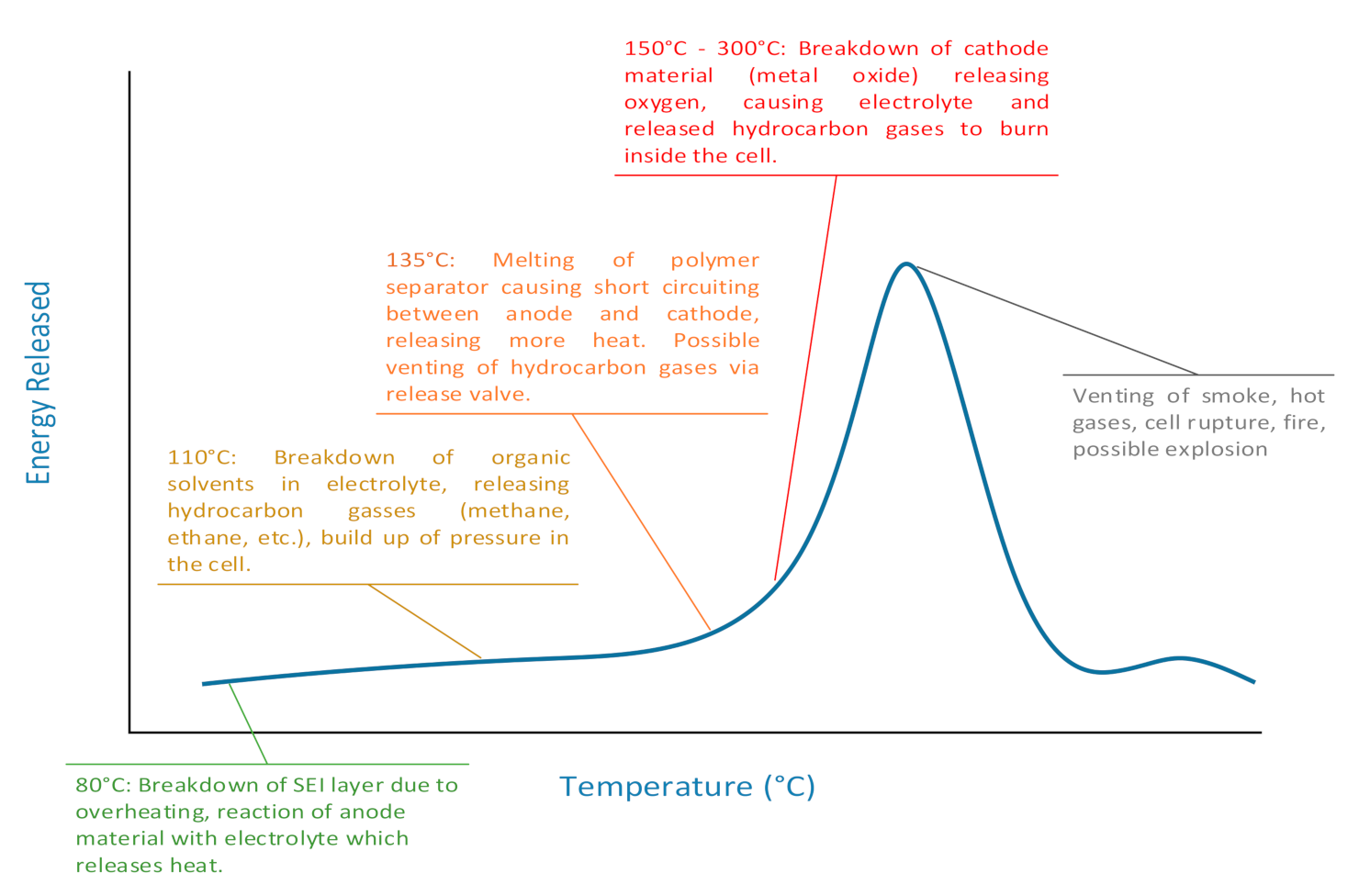
4.1.2. Functional Description

In recent literatures, lithium-ion battery chemistry, function, and failure modes have been described extensively. A study on the consequences of lithium-ion cell failure and subsequent fire has been performed that demonstrated the need for fire suppression systems to mitigate the fire risk of lithium-ion batteries [41,42].

4.2. Fire Risk—Lithium-Ion Batteries

The various failure modes of lithium-ion batteries are shown in Table 3, many of which lead to overheating. Safe operation of lithium-ion batteries can be assisted by a Battery Management System, however this is also has its own failure modes and vulnerabilities.
Most pertinent to fire risk is thermal runaway, a process where the uncontrolled temperature increase of a cell can lead to self-sustaining exothermic chemical reaction causing fire and potentially explosion [42].
For a large submarine which will require thousands of cells to be tightly packed, this brings the added risk of cascading thermal runaway where the heat from cells undergoing thermal runaway is transferred to neighbouring cells, in turn triggering further thermal runaway [39]. The typical stages of thermal runway are described in Figure 5 [40]. Thermal runaway can occur at temperatures of 150 °C, although the temperature at which thermal runaway is triggered can depend on failure mode, cell geometry and cell chemistry [43].
Heating of the deck and bulkheads surrounding the batteries can lead to localised weakening of the submarine structure and ignition of materials in adjacent compartments.

4.2.1. Fuel Sources

Lithium-ion cells are typically filled with a flammable electrolyte of which there will be several hundred tonnes in each battery compartment due to the large number of cells required to power a large submarine [39]. Further, some design configurations will require relatively high capacity cells to be used which contain more electrolyte per cell [43].

4.2.2. Ignition Sources

A key aspect of thermal runaway which contributes to its significant fire risk profile is that fact it does not require an external ignition source to start a fire. A lithium-ion cell contains everything required to reach significant temperatures once thermal runaway has been triggered which can ignite surrounding materials as well as produce high-temperature, flammable gasses which will readily produce a flame if vented from the cell. Many lithium-ion cells are designed to vent gases in the event of thermal runaway to prevent explosion leading to flaming fire and smoke.

4.2.3. Technology Maturity

Relatively low capacity (e.g., up to 5 Ah) lithium-ion batteries are found in many consumer electronic devices and have reached a reasonable level of maturity, particularly in the last five years (2015–2020) as considerable investment has been made to improve safety measures and designs in response to serious fire safety concerns in a number of industries and domains [44]. Note that the first edition of the International Air Transport Association’s operator’s guidance document for lithium batteries was released in 2015 [45].
In the maritime domain, the US Navy released its Lithium Battery Systems Navy Platform Integration Safety Manual in 2011 [46] and have continued their lithium-ion battery safety research [47].
Larger cells (e.g., 20–100 Ah+) are still relatively immature however and their application in large, manned submarines is still in its infancy with some use in smaller swimmer delivery vehicles and Unmanned Underwater Vehicles (UUV) [48,49]. The Japanese Self-Defense Force have recently commissioned a 4200 tonne Soryu-class submarine with GS Yuasa built lithium-ion batteries [50] in 2020 [51]. The People’s Liberation Army (PLA) in China is in the process of developing lithium-ion battery technology for use in its submarines within the next five years [52]. Other notable submarine designers, including ThyssenKrup Marine Systems (TKMS), have completed research and development on the design of a lithium-ion main storage battery for submarines, however many of these designs are yet to be implemented [53].
Although one large conventional submarine operator has just begun to operate a lithium-ion powered boat, the feasibility and safety integrity of lithium-ion batteries in large, manned submarines is yet to be truly tested.

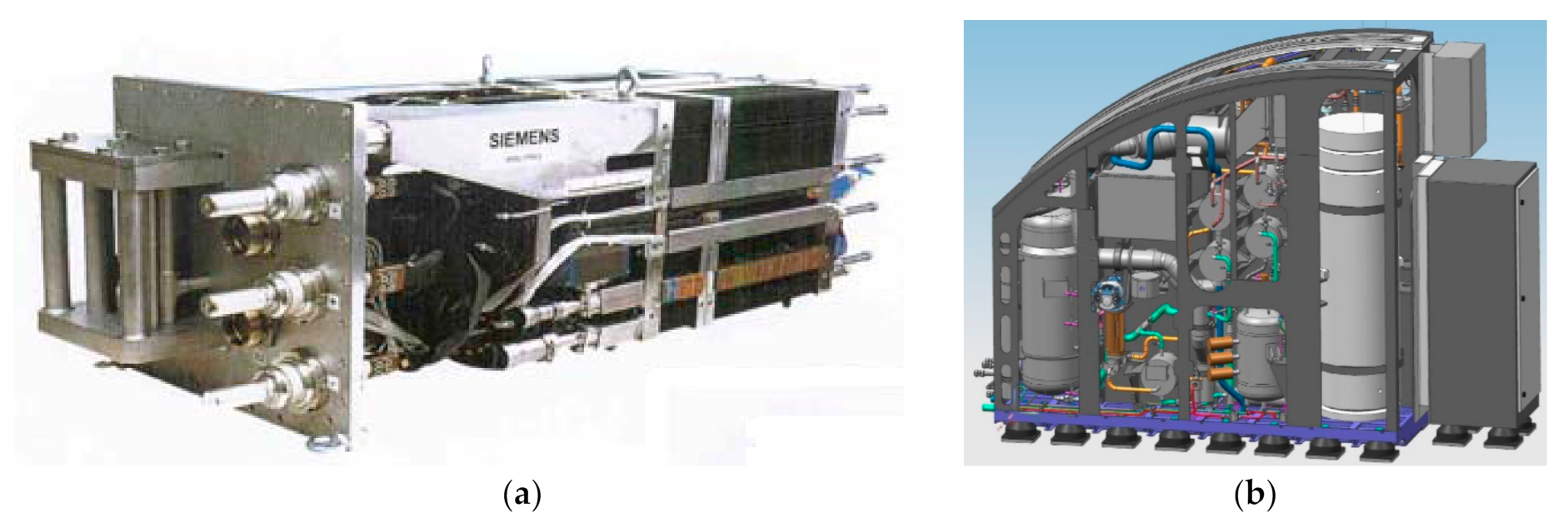
4.3. Hydrogen Fuel Cell

4.3.1. Future Submarine Context

The Polymer Electrolyte Membrane (PEM) Fuel Cell (PEMFC) is one of several technologies able to provide AIP for conventional submarines. The primary objective of AIP is to extend a submarine’s underwater endurance and range, thereby increasing overall stealth and enhancing operational flexibility. AIP basically allows the submarine to produce power from stored fuel and oxygen to recharge depleted batteries and or provide direct power to the propulsion system and other functions of the submarine whilst submerged. This greatly reduces the need to frequently return to periscope depth to snort and recharge batteries and therefore significantly reduces the risk of being detected. The current Australian Collins Class submarine is of traditional conventional submarine design with lead-acid batteries being the only source of power beyond periscope depth. A range of AIP technologies, along with lithium-ion batteries, can be considered for future submarines as a means of increasing capability and improving stealth profile.

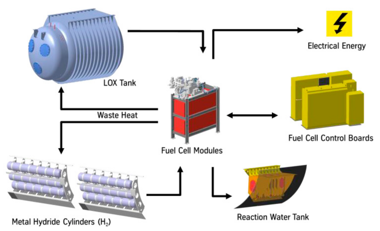
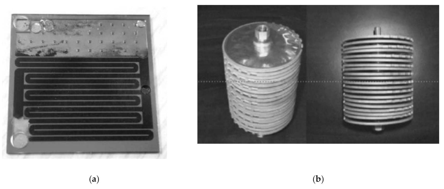
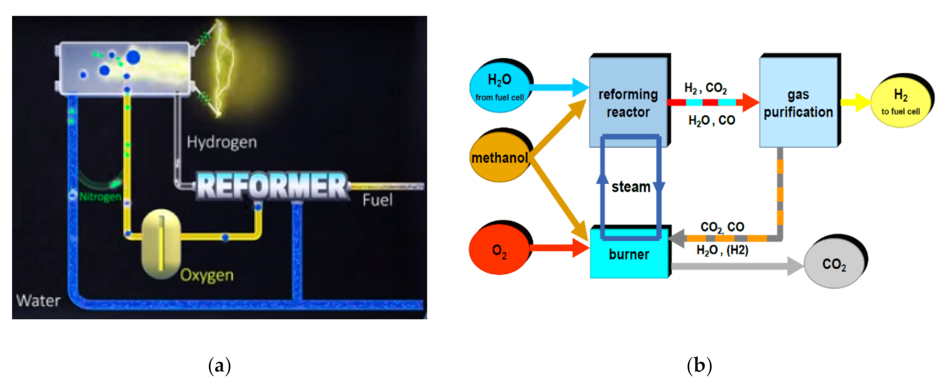
4.3.2. Functional Description

Hydrogen fuel cells utilise an electrochemical reaction between hydrogen and oxygen to produce electricity as shown in Figure 6. This requires a constant supply of hydrogen and oxygen gas, the storage of which is a challenge for submarines. Most AIP technologies require high pressure liquid oxygen (LOX) to be stored on-board. Storage methods for hydrogen are varied however, ranging from metal hydride cylinders to carbon based fuels which require a reformer to extract and convert the stored hydrogen into a form that is usable by the fuel cell.
The configuration shown in Figure 7 utilises metal hydride cylinders and a LOX tank. Waste heat from the fuel cell is used to release hydrogen gas from the storage cylinders and evaporate the LOX required to fuel the PEMFC. Water produced through the operation of the fuel cell is retained to maintain stability on the submarine as fuels are expended [55].
Although this configuration has proven feasible in a number of submarines, the storage efficiency in terms of the weight of metal hydride required to store sufficient hydrogen precludes its use on larger submarines greater than 2000 tonnes displacement [55]. This has driven the development of reformer technology which effectively involves the storage of hydrogen in liquid fuels such as methanol, ethanol and diesel and then extracting the hydrogen at the time of use within the fuel cell.
Steam reformation of hydrocarbon gases and liquids is a popular hydrogen production method both for fuel cells and other applications. The designs and configurations are widely varied, but generally consist of three main components [56]: (1) a burner or furnace; (2) a reactor, usually either a catalyst loaded microchannel heat exchanger; or an array of hydrogen permeable membranes with integrated catalyst; and (3) a gas purification system.
A picture of a microchannel heat exchanger or micro-reactor is shown in Figure 8a. An integrated membrane reactor module is shown in Figure 8b.
The reforming process varies depending on system design, however generally requires heating of the carbon based fuel or feedstock with steam and oxygen to produce mostly H2 gas and CO2. This requires the use of waste water from the fuel cell whilst LOX stores must feed the reformer as well as the fuel cell. Output gases from the reformer are then passed through a gas purification system which removes unwanted gases so that sufficiently pure hydrogen can be passed into the fuel cell [58].
To maintain equilibrium within the submarine, carbon dioxide gas must be vented to the open sea whilst seawater is taken on as ballast [55]. This requires an exhaust treatment system which ensures exhaust gases can be released underwater without compromising the acoustic or thermal signature of the submarine. The system consists of two key components: a CO2 compressor for release of gas at extended depths and a gas dissolution unit which dissolves exhaust gases into seawater prior to release from the submarine [55].
A diagrammatic example of a fuel cell operating with a reformer is shown in Figure 9a. Depending on the feedstock chosen, varying amounts of LOX, fuel and compensatory ballast volume is required due to the chemical composition of the feedstock and the reactions necessary to obtain usable hydrogen.
A comparison, across three different feedstocks, of the collective volume required to achieve an equivalent AIP capacity is shown in Figure 10.
The exact volume of reformer feedstocks would be dependent on several factors, mainly the characteristics of the fuel cell such as size and efficiency as well as the amount of energy—and therefore hydrogen—desired to be stored by the system. Figure 10 is intended to show the relative difference between feedstock options in terms of total volume of fluids required to store an equivalent amount of hydrogen suitable to feed the fuel cell. The relative differences are based on the variances in molecular construct of the feedstocks with respect to hydrogen ratio (e.g., methanol-CH3OH; ethanol-C2H5OH; diesel-C12H23[average]), and the differences in physical properties of each feedstock.
Methanol appears to provide the best volumetric solution, but also has some advantages over the other feedstocks [55] such as higher molecular hydrogen to carbon ratio; most efficient reforming process; lower reformation temperature: 250 °C compared to >700 °C (ethanol) and >850 °C (diesel); higher purity compared to diesel etc.
It should be noted that using diesel as the feedstock offers the possibility of shared fuel storage between the reformer and suitably designed main engines which could provide enhanced operational flexibility. In either case, it is important to consider the choice of feedstock on fire risk in terms of fuel volatility and AIP operational temperatures and pressures.
The steam reformers likely to be incorporated onto a submarine should not be confused with the large industrial steam reformers used for high volume production of hydrogen gas. An example configuration of a methanol reformer for a submarine is shown in Figure 9b. In this configuration, methanol is combusted with oxygen in the burner and used to heat steam. Steam is used as the heat carrying medium to bring the reforming reactor up to the required temperature of 250 °C. Water and methanol are fed into the reforming reactor at a water/methanol ratio of around 1.5. Steam and methanol pass through the reactor, consisting of a series of tubes much like a heat exchanger or alternatively through a series of permeable membranes. The reactor has an inbuilt catalyst, usually copper-based, which aids the reforming reaction that converts methanol into a gas mixture containing mostly hydrogen. The hydrogen is then passed through the gas purification system before being fed into the fuel cell. Remaining gases are recycled through the burner and carbon dioxide is passed to the exhaust treatment system before being discharged overboard.

4.4. Fire Risk—Hydrogen Fuel Cell

4.4.1. Failure Modes

The PEMFC, reformer and exhaust treatment systems consist of many electrical and mechanical components, most of which do not pose a significant fire safety risk. The key components of their AIP system with respect to fire risk are the burner and reforming reactor in the reformer system, LOX and fuel storage tanks, hydrogen purification vessels and associated fluid distribution systems. A review of the Hydrogen Tools Lessons Learned database which contains over 300 incident reports for failures of hydrogen and fuel cell technologies shows that the most common probable cause was Equipment Failure, happening 26% of the time [60]. This far outweighs the next most common cause of Human Error (10%) and appears to be the main risk factor. Equipment failure and human error are the main causes of failure. Other 64% can be taken from [60].
Of the recorded incidents citing equipment failure as the probable cause, over 50% were due to piping, valves, flanges and or tubing. Fluid leaks often occur at the interfaces, interconnection points or in joints and discontinuous sections of distribution lines. It is at these connection points that seals, flanges, gaskets, fasteners and other components can fail and cause a fluid leakage [61]. Pipe ruptures, split tubes and similar failures have occurred but are less common. It should be noted that only one equipment failure event was listed as being caused by the fuel cell itself, with a short circuit causing melting of a tube filled with hydrogen which caused a small fire [60].
As with the hydrogen fuel cell, LOX system failures relating to loss of fluid containment are the most critical with respect to fire risk. Although not flammable itself, oxygen supports and accelerates combustion. An oxygen leak will lead to a localised higher than normal concentration of oxygen which can significantly reduce the ignition temperature and energy required to ignite materials [62].
Failure modes of steam reformers are largely dependent on design and configuration, however those concerning fire risk also relate to loss of fluid containment. The furnace can operate at pressures of up to 100 bar, the reactor can operate in excess of 50 bar depending on design and temperatures in excess of 800 °C depending on the feedstock. Failure modes are similar to distribution systems and other comparable systems like heat exchangers, ranging from flange, gasket and valve failures to corrosion and fatigue related cracking and fracture [61].
The primary failure modes which could lead to a significant fire incident relate to containment of the feedstock, hydrogen gas and LOX. Common failures of a hydrogen fuel cell AIP system are summarised in Table 4. It should be noted that for the purposes of this research and any subsequent failure mode and risk assessments, it is assumed that control systems and related components have been designed to an appropriate Safety Integrity Level such that the probability of critical failure caused by the control system has been reduced to negligible levels.

4.4.2. Fuel Sources

The primary fuel sources in a hydrogen fuel cell system including a steam reformer are the feedstock and hydrogen gas. The feedstock is likely to be either methanol, ethanol or diesel fuel which are all highly flammable, especially the alcohol feedstocks. The volume of feedstock held will depend on submarine power requirements and the desired range requirements of the AIP system, however for the purposes of the large submarines, is expected to be several hundred litres at the least. Hydrogen gas is highly flammable, significantly more so than the feedstock. It will be reformed from the feedstock as needed by the fuel cell and therefore only relatively small volumes of hydrogen gas should be present at a given time, and only during operation of the AIP system.

4.4.3. Ignition Sources

The most apparent ignition source in this AIP system is the burner in the furnace of the reformer, although this will be concealed and not openly exposed to many of the potential fuel sources. More importantly, it is the heat created by the furnace which is passed through the AIP system, mainly via steam, which creates several hot surfaces of high enough temperature to ignite any of the nominated fuels.
There are also several electrical components in the system for the transmission of electricity generated by the fuel cell and for the controllers and monitoring equipment embedded within the system. These have the potential to create electrical sparks during malfunction or failure events.
Although not an ignition source or fuel in itself, perhaps the most hazardous component of this and any other AIP system is the LOX. Oxygen is a strong oxidiser that vigorously supports combustion and its reactivity increases with increasing pressure, temperature and concentration [63].
Many materials not considered to be flammable in normal conditions become readily ignitable in concentrated oxygen, including metals and non-metals. This also means that the energy required to ignite a material reduces with increasing oxygen concentration. For example, the minimum spark energy for hydrogen gas in air under normal operating conditions is 0.019 mJ, however in pure oxygen is less than one fifteenth of this at just 0.0012 mJ [63]. Similarly, grease or lubricant which is stable under normal operating conditions may ignite when exposed to concentrated oxygen. In an example which illustrates how oxygen acts as a fire risk multiplier, flammable liquid which may have accumulated slowly via a small leak could remain benign for extended periods, however would ignite if exposed to sufficient oxygen.

4.4.4. Technology Maturity

Hydrogen fuel cells have seen extensive development and application in a variety of industries including the energy and automotive sectors [64]. Over the last decade, PEMFCs have been used on submarines in service with German, Italian, Israeli and Russian Navies [65], and could be considered to be a relatively proven submarine technology. A Siemens PEMFC is shown in Figure 11a.
Steam reformers have been used in large scale hydrogen production or fuel processing for fuel cells for many years now with methane the most popular choice of feedstock. This technology has been successfully developed and integrated with fuel cells using gaseous and liquid feedstocks for smaller applications including stationary power sources, road vehicles and military applications [64].
In terms of application to conventional submarines, steam reformers have not yet seen integration into a submarine, and hydrogen fuel cells have not yet been integrated into large conventional submarines of 3000 tonnes displacement or greater. In a drive to develop fuel cell based AIP for larger submarines, a number of companies have been developing PEMFC-reformer systems for submarines. TKMS have successfully integrated a methanol reformer with the Siemens FCM120 hydrogen fuel cell in a land-based test facility. The complete solution reportedly completed more than 1500 h of successful operation. As of mid-2015, the system is in the process of being submarinised before further land-based testing [55]. The proposed submarine module is shown in Figure 11b.
Naval Group Australia or French Directorate for Naval Construction also reported their development and successful land-based testing of a similar AIP configuration [59] and Navantia completed designs for a bio-ethanol fed fuel cell AIP solution, to be integrated into the S-80 submarines and in service from 2016 onward [63].
In summary, steam reformer and fuel cell technology has seen extensive use and integration in a variety of industries, however whilst there has been extensive development and testing for submarine-based systems, the PEMFC-reformer AIP configuration currently has no proven service history on a submarine.

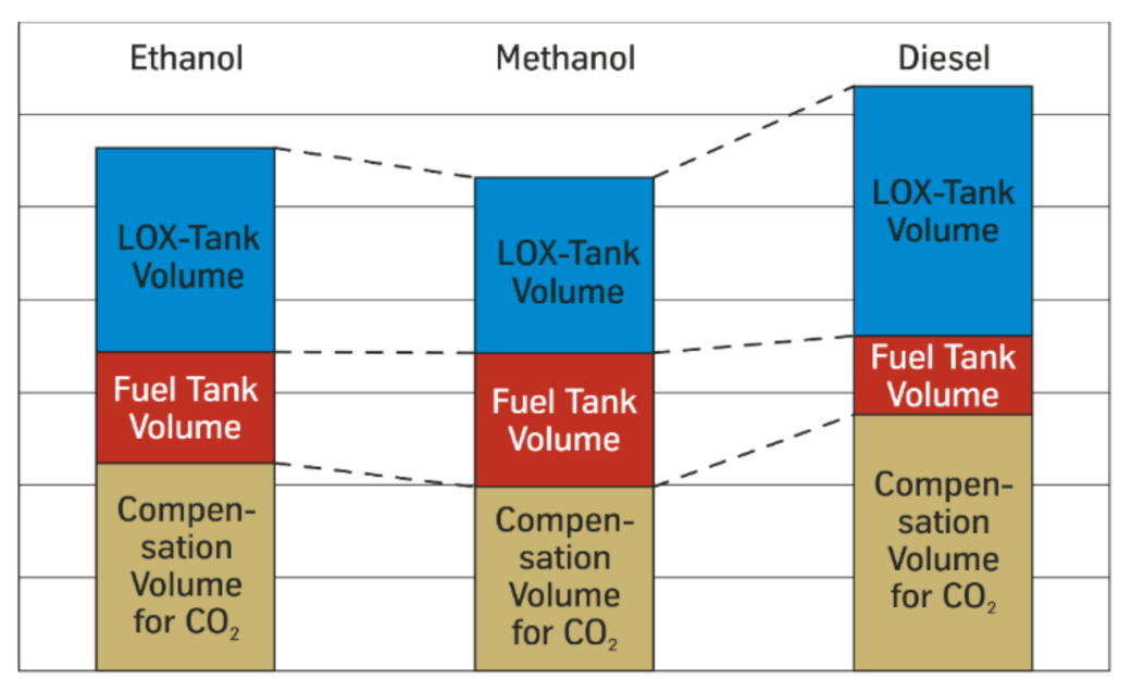
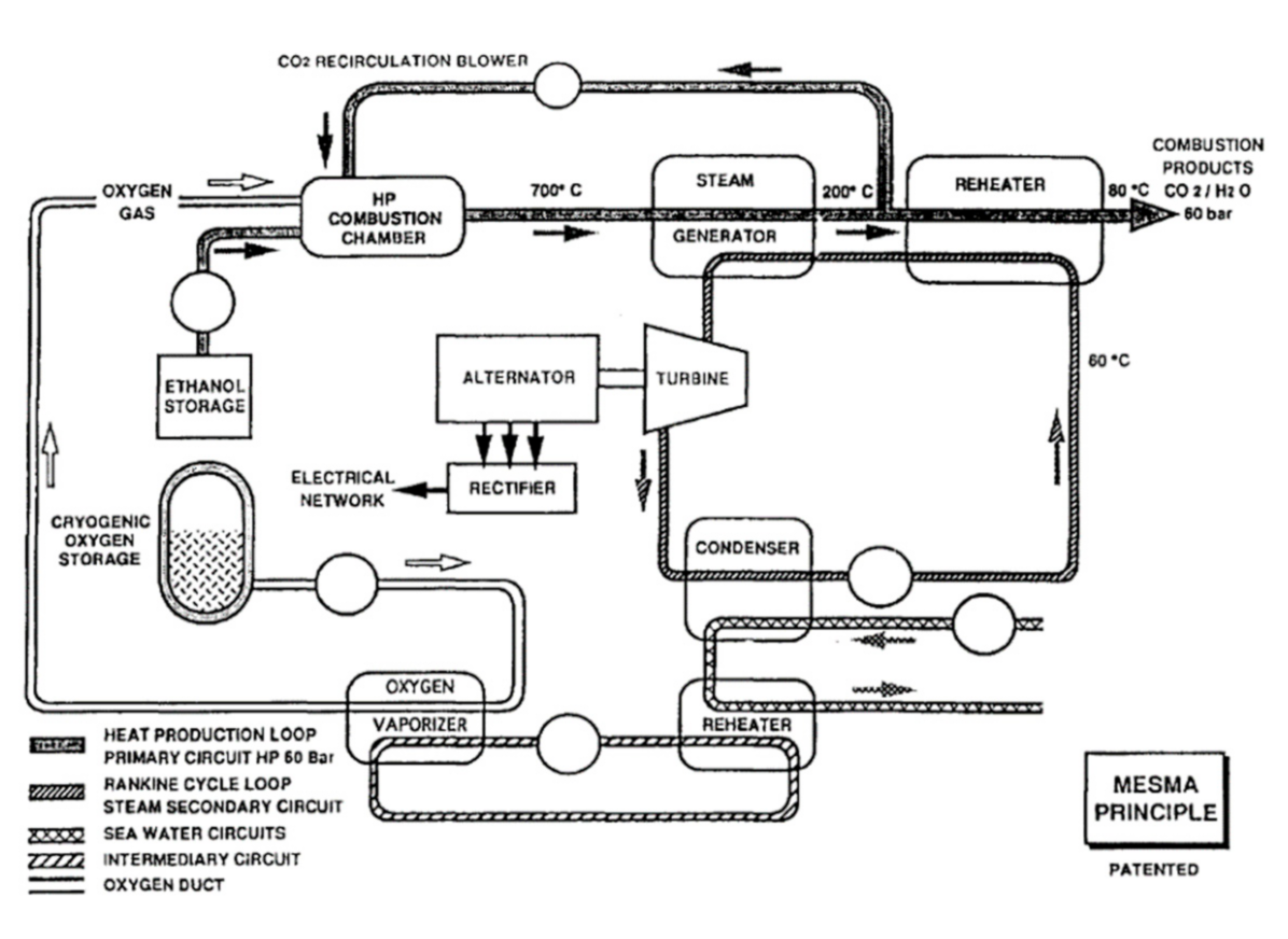
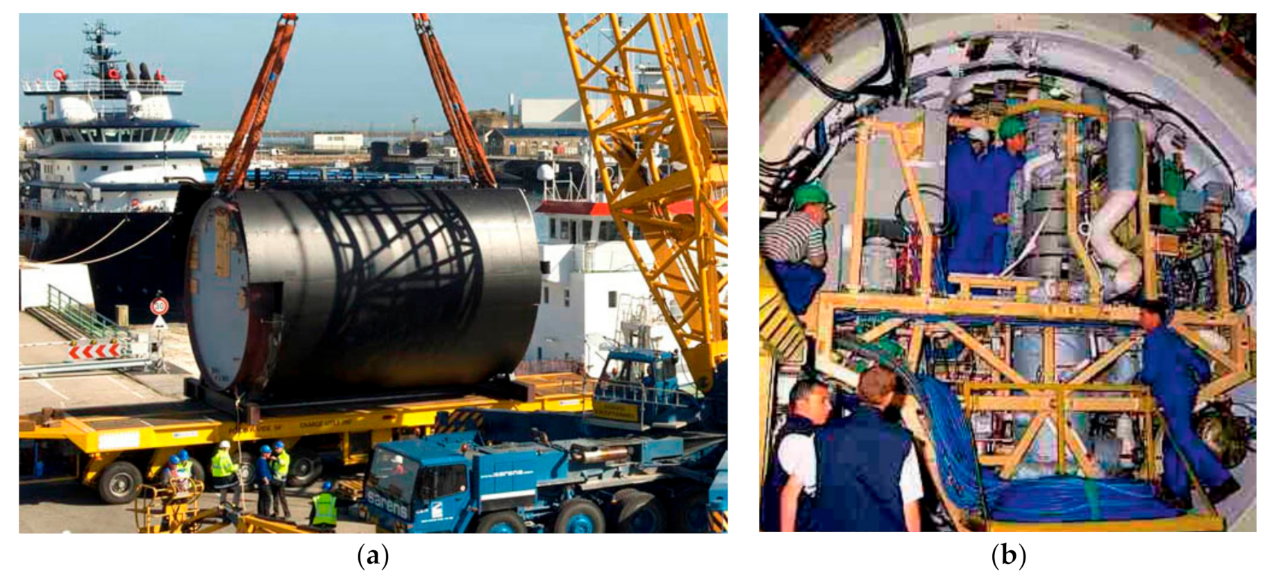
4.5. MESMA Steam Turbine

Future Submarine Context and Functional Description

Module Energie Sous-Marin Autonome (MESMA) is able to generate electricity whilst a submarine is submerged and is another technology solution that is able to provide AIP for conventional submarines. MESMA uses a closed cycle steam turbine to produce electricity in a configuration that is seen as a derivative of a nuclear submarine’s power plant, only using non-nuclear means to generate steam. LOX is evaporated, mixed with fuel and the mixture is ignited by a retractable tungsten electrode and burnt in a combustion chamber. Exhaust gases up to 700 °C are used to heat water which produces the steam required to turn the turbine. The turbine drives an alternator-rectifier which generates direct current power for the submarine [67]. A schematic of the MESMA system is shown in Figure 12.
Initially, methanol was used as the fuel, however ethanol was determined to be a more suitable option due to its lower toxicity and relatively similar performance. Ethanol is stored in a cofferdam which enables water to be taken on to compensate for weight changes as fuel is burnt and exhaust gases leave the submarine. LOX is stored at low temperature as it enables a greater amount of oxygen to be carried, despite requiring a pump to feed the combustion chamber. The oxygen storage and distribution system is completely segregated from the rest of the MESMA system to reduce risk and maintain safe operations.
A number of loops are used within the system to regulate temperature and improve efficiency by recycling heat. Upon exiting the steam generator, some of the cooler exhaust gases are rerouted back through the combustion chamber to regulate temperature. The remainder of exhaust gases are passed through a water re-heater which simultaneously cools exhaust gases in preparation for release outside the submarine and preheats water cycling back through the steam generator. Exhaust gases exit the system at around 60 bar and can therefore be released from the submarine at depth without the need for an exhaust compression system. Similarly, cool seawater passes through the condenser to cool outgoing steam from the steam generator before using the thermal energy absorbed to heat a separate water circuit which is used to evaporate the LOX [67].

4.6. Fire Risk-MESMA Steam Turbine

4.6.1. Failure Modes

From a fire risk perspective, MESMA is similar to a steam reformer used to produce hydrogen for a fuel cell. Fuel and liquid oxygen is burned in a combustion chamber to heat steam which in this case is used to turn a turbine as opposed to providing heat for hydrogen production. Therefore the mechanical and electrical components that make up the system are also similar and the system as a whole exhibits similar failure modes and consequences.
The key components with respect to fire risk are the combustion chamber, LOX and fuel storage tanks, and associated fluid distribution systems. As with similar systems, the primary failure modes which could lead to fire relate to containment of fuel and LOX. Common failure modes for the MESMA system which could lead to loss of containment and consequently fire are summarised in Table 5.

4.6.2. Fuel and Ignition Sources

The main fuel source for the MESMA system is ethanol which is highly flammable. Similar to other AIP systems, the volume of ethanol held will depend on the range and power requirements of the submarine, however will be several hundred litres at minimum. The electrode within the combustion chamber ignites the oxygen-fuel mixture, however is concealed and should not provide a source of ignition for an uncontrolled fire under normal operating conditions.
Similar to other AIP systems, MESMA requires a fuel, ethanol in this case, to be burnt in order to generate heat and produce steam to generate electricity. As a result, there will be many hot surfaces within the system whilst it is being operated, some in excess of 700 °C which is sufficient to ignite a fuel leakage or spray.
As discussed in previous sections, whilst not technically being an ignition source, LOX significantly increases the risk of ignition. System failures that wouldn’t normally lead to a fire under normal conditions could escalate to a significant fire incident given heightened concentrations of oxygen.

4.6.3. Technology Maturity

Although similar technologies exist, MESMA was developed exclusively for use in a submarine and has no development or service history in other industries or applications. Development of MESMA began in the mid-1980s when France-based Bertin Company designed a system initially fuelled by methanol [67]. Since then the technology has been jointly developed with Naval Group Australia and successfully integrated into a number of conventional submarines.
The first submarine fitted with MESMA was an Agosta 90B submarine built for the Pakistan Navy and commissioned in 2008. A further two Agosta 90B submarines have since been retrofitted with MESMA and were delivered in 2011 [68]. A completed MESMA module, ready for integration into one of the Agosta 90B submarines, is shown in Figure 13a. The inside of a MESMA module built for the Agosta 90B submarine is shown in Figure 13b.
MESMA is also offered on the latest AM-2000 variant of the Scorpène class submarines of which the Indian Navy currently have three on order and the Brazilian Navy four, although none of these submarines have been completed or commissioned [71].
MESMA has been under development for over 30 years and has nearly 10 years’ service history in conventional submarines, though those submarines are considered to be medium sized at around 2000 tonnes displacement. MESMA currently has no service history in large conventional submarines of 3000 tonnes or greater.

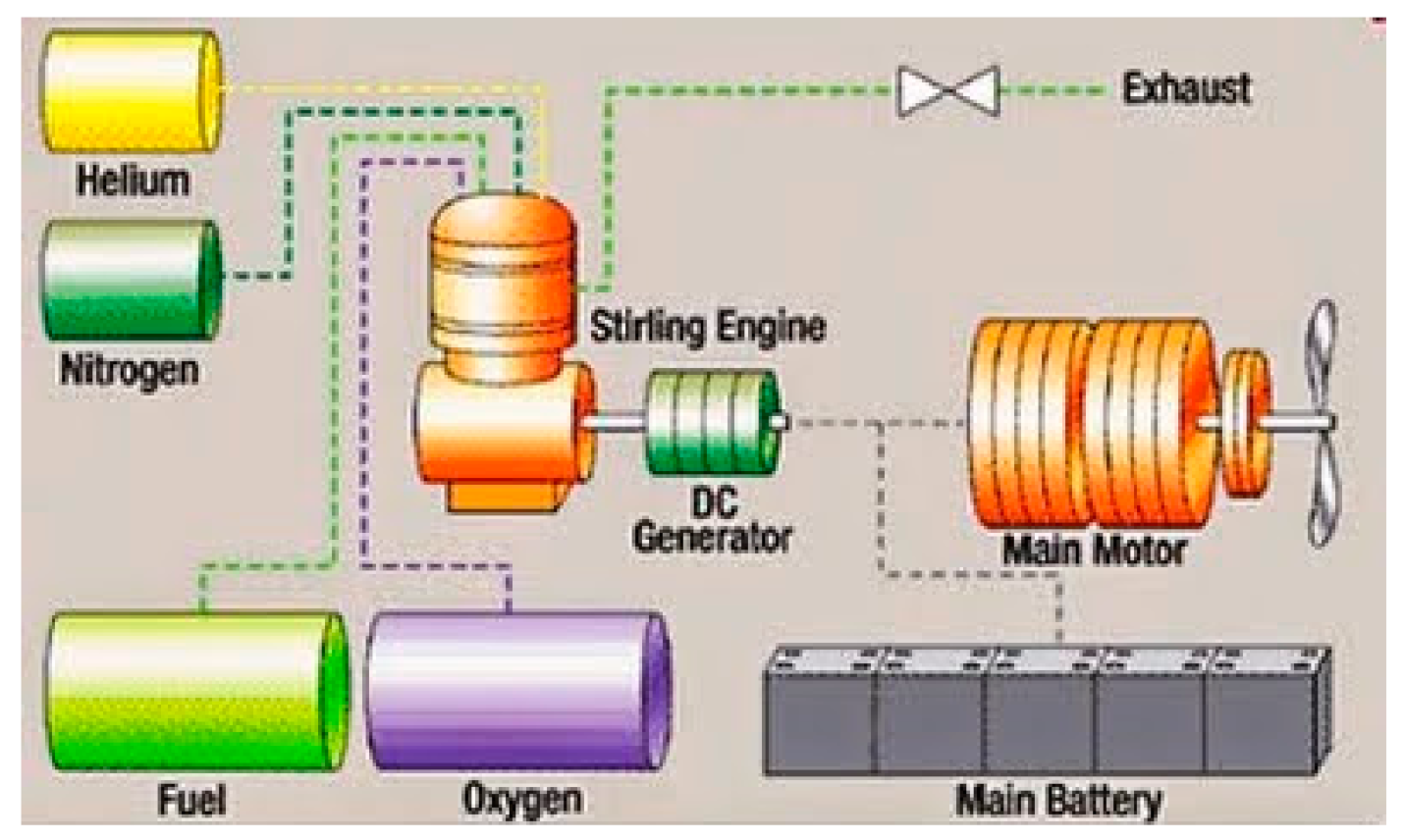
4.7. Stirling Engine

Future Submarine Context and Functional Description
A Stirling engine can be run whilst a submarine is submerged and used to generate electricity at depth, allowing the submarine to stay submerged for extended periods. Stirling engines are very similar to conventional internal combustion engines, the key difference being that fuel is combusted and the resultant heat is applied externally to a working fluid in a closed system [72]. A Stirling engine operates on a closed regenerative thermodynamic cycle which utilises differing temperatures of a gaseous working fluid to achieve cyclic expansion and compression in order to convert heat to work [73].
There are many types of Stirling engine, though their function normally involves the working fluid moving between a heated and cooled part of the engine. The movement of the gas is used to drive a number of pistons which, in the case of a submarine AIP system, drive an alternator to produce electricity. The typical configuration of a Stirling engine AIP system for a submarine includes LOX, low sulphur diesel fuel and helium gas as the working fluid.
LOX is evaporated, mixed with the fuel and burnt in the combustion chamber at high pressure to provide a source of heat [74]. The engine cycle operates as follows:
  • Helium gas enclosed within the Stirling engine is passed through tubes in the combustion chamber where it is heated.
  • Pistons push the helium to through a regenerator which absorbs heat, and a cooler which further cools the gas before entering the lower, cool part of the cylinder.
  • Compression of the cooled gas assists the double acting piston to push the cool gas back through the tubes, past the cooler and past the regenerator which transfers the heat absorbed earlier back to the gas.
  • Gas moves back through the heater tubes in the combustion chamber and into the hot part of the cylinder where it expands, pushes the piston down and restarts the cycle.
The cyclic movement of the pistons is used to turn a crankshaft connected to a generator which provides electricity to the submarine. Exhaust gases from the combustion chamber are dissolved in seawater, usually at sufficiently high pressure to enable release overboard without the need for a compressor. Helium and nitrogen are used to purge the combustion chamber when required and seawater is used to provide cooling. A schematic of a typical Stirling engine AIP configuration is shown in Figure 14.

4.8. Fire Risk-Stirling Engine

4.8.1. Failure Modes

As per the other AIP solutions discussed, the Stirling engine AIP systems have a similar make up of mechanical and electrical components. In this case, fuel and liquid oxygen is burned in a combustion chamber to heat the working fluid contained within the Stirling engine. Therefore the system exhibits similar failure modes and consequences to the MESMA and PEMFC systems.
The key components with respect to fire risk are the combustion chamber, LOX and fuel storage tanks, and associated fluid distribution systems. The primary failure modes which could lead to fire relate to containment of fuel and LOX. Common failure modes for the Stirling engine system which could lead to loss of containment and consequently fire are summarised in Table 6.

4.8.2. Fuel Sources

The main fuel source for the Stirling engine AIP system is diesel fuel. Depending on whether the main propulsion engines and the AIP system are able to run on the same fuel, the amount of diesel fuel on-board the submarine could range from several hundred litres if a separate fuel is required for the Stirling engine to several thousand litres if using a common fuel type. Helium gas is used as the working fluid for the Stirling engine, and as a purging gas along with nitrogen. Neither of these gases are flammable and would not provide a fuel source for a fire.

4.8.3. Ignition Sources

Diesel fuel is combusted in oxygen within the combustion chamber, however this is concealed and should not serve as an ignition source under normal operating conditions. As with other AIP systems, Stirling engines require heat to operate. The flow of the working fluid and exhaust gases through the system at temperatures up to 900 °C [76] creates many hot surfaces which can serve as ignition sources. Furthermore, as per other AIP systems and as discussed earlier, LOX significantly increases the risk of ignition. System failures that wouldn’t normally lead to a fire under normal conditions could escalate to a significant fire incident given heightened concentrations of oxygen.

4.8.4. Technology Maturity

The invention of the Stirling engine dates back to 1816 when it was first patented by inventor Robert Stirling [73]. The technology has a long history of development, however, although considered a stepping stone to the development of many other technologies, Stirling engines have limited use in niche applications today. Due to its ability to operate with any heat source and its relatively quiet operation, one of those niches is submarine AIP.
Despite earlier efforts by the US Navy and others, development of Stirling engines as an AIP solution for submarines did not reach the point of integration until the late 1970s when Kockums Submarine Systems in Sweden began its development program. This resulted in the first fully functional Stirling engine AIP module being integrated into a Näcken class submarine in 1988 [74]. Further development of this technology was subsequently integrated into the Swedish Gotland and Södermanland class submarines. The Singapore Navy now operates two ex-Gotland class submarines, the Archer class, both with Stirling engine AIP.
Importantly, Stirling engines are the only AIP technology with a service history in large conventional submarines, having been in-service on the Japanese, 4200 tonne Soryu class submarines since 2009. With several operators, over 30 years’ service on medium-sized conventional submarines and over 10 years’ service on large conventional submarines, Stirling engines are perhaps the most mature submarine AIP technology.

5. Fire Risk Assessment

5.1. Overview

A high-level, semi-quantitative risk assessment of the fire safety critical, emerging submarine technologies examined above has been conducted and is presented next. The primary purpose of this analysis is to establish a priority ranking for further research and testing to advance the safe integration of technologies that may enhance conventional submarine capabilities.

5.2. Risk Assessment Framework

MIL-STD-882D—Standard Practice for System Safety [77], which forms the basis of the RAN Safety Management Manual, has been used as the basis for this analysis. The risk matrix is shown in Table 7 whereas likelihood and consequence definitions are outlined in Table 8. In Table 7, in each box three values are given representing three sets of values. The first set represents base values and second (italic) and third (bold) sets represent values for sensitivity analysis. It is to be noted that the low Mishap Risk Assessment (MRA) values indicate higher risk. For example, risk values (base case) between 1 and 5 are considered to be extreme risk and generally classified as intolerable (highlighted with red in Table 7) whereas (base) values between 18 and 20 (highlighted with green in Table 7) are classified as low risk and generally classified as acceptable. Yellow and blue highlights fall in high and medium risk categories.
The likelihood of occurrence is assessed as the probability that the event will happen in any one submarine across a fleet of 6–12, during a nominal 30-year service period. The consequence is assessed as the impact to the submarine on which the event occurs.
Risks have been assessed without consideration for mitigation measures such as fire suppression systems. This does not preclude ranking of systems in terms of their fire risk which is the focus of this assessment. Fire safety system options are wide and varied and should be considered at the whole of platform level. The configurations and the effectiveness of various fire prevention, detection and suppression systems in conjunction with the technologies under consideration is an extensive subject and will not be reviewed as part of this semi-quantitative assessment. Note that, however, the technology maturity weighting factor accounts for reliability, safety integrity and the availability of mitigation measures that may be applied.

The Effect of Technology Maturity on Risk

The maturity of the technologies under consideration has been discussed in the sections above and has been considered in the context of large future conventional submarines. A technology maturity weighting factor will be used to augment the overall risk assessment to account for the following key risk factors:
  • System reliability: The level of reliability of system components and the integrated system itself is dependent on the maturity and rigour of associated design and manufacturing standards. This is largely dependent on the maturity of the technology inherent in the system and the scale of its use and production. The higher the reliability, the lower the probability of failure and the lower the overall risk.
  • Safety integrity: Whilst related to reliability, safety integrity is closely connected to the service history of a technology and the collective knowledge of how the system operates and fails. The longer a system has served in a particular application, the better the operational risk and safety factors are able to be understood which leads to more robust system design and better overall safety. In the context of fire risk, this can lead to fewer failures that cause fires and or less severe fires should they occur.
  • Effectiveness of available mitigation measures: Referring specifically to fire risk, the nature of a technology’s operation, the chemicals used and the environment in which it operates all affect the availability and effectiveness of preventative and reactionary mitigation measures. The level of understanding about which fire prevention, detection and suppression systems work best with a certain system is dependent on the maturity of the technology, the degree of testing and development and the length of its service in a submarine environment.
In order to account for the maturity of the technologies under assessment, a technology maturity weighting factor will be used to augment the overall risk assessment to account for the key risk factors discussed above. This will be directly related to length of service history and extent of testing and development in relation to: (1) Large conventional submarines (approximately 3000 tonnes displacement and above); (2) Small to medium conventional submarines (1000 to 2500 tonnes); and (3) Other industries and applications. Technology maturity weighting (TMW) factors are defined in Table 9. Three sets of values are given representing TMW base and sensitivity values. Base risk scores are taken from MIL-STD-882D—Standard Practice for System Safety [77]. Arbitrary sensitivity values were used to scale the base risk scores to provide a risk rating range for each technology in order to account for uncertainty in the risk assessment. It is to be noted that low weighting factors relate to low technology maturity and will reduce the MRA value which, in the context of the above risk framework, results in an overall higher level of risk. The adjusted MRA will be MRA × TMW.

5.3. Assessment

5.3.1. Scenario

There are many scenarios under which fires of various magnitudes may occur, however for the purpose of establishing the overall risk associated with each technology, the worst case credible scenario has been considered. The worst case scenarios across all technologies are similar, particularly for AIP systems, given that a severe fire is likely to have catastrophic consequences no matter the source or cause.

5.3.2. Quantification

The semi-quantitative risk assessment is summarised in Table 10 with scoring from base values.
All the AIP systems considered require LOX, some sort of liquid fuel and a combustion reaction to release the heat or products required to generate electricity. Despite the method used, all these systems are comprised of similar components and therefore, carry the same risks and have equal unadjusted MRA values. Each of the AIP solutions are at different levels of maturity which is the only point of difference in terms of risk. The PEMFC-reformer combination is the least mature, as a reformer has never served on a submarine before and therefore this solution carries a higher risk than the other solutions. Conversely, the Stirling engine has seen service on medium and large sized conventional submarines, and being the most mature technology, it has the lowest fire risk.
Lithium-ion batteries perform a different role on the submarine and are fundamentally different to the other technologies in terms of function and operation. Lithium-ion batteries have a higher probability of fire due to the fact that so many—up to several thousand—individual cells will be required to meet the power requirements of the submarine. This means there are several thousand points of failure such that if just one cell fails, due to the nature of thermal runaway, it could cause a severe fire. As a result, lithium-ion batteries have the lowest unadjusted MRA value. Lithium-ion batteries are also the least mature of the technologies assessed with regard to integration into submarines. Not only have they not been used on a submarine before, but the technology is also facing fire safety issues in other applications and industries. This further increases the level of risk and makes lithium-ion batteries clearly the highest risk technology and the one in need of the most work prior to integration into future submarines.

5.3.3. Sensitivity Analysis

It may be argued that the scoring system adopted as base values is a subjective one. The ranking may be changed if the scoring system is changed. Hence, we have conducted a sensitivity analysis where the scoring system has been changed and the effect of this in the ranking of the compartment has been analysed. Here we have considered two additional scoring systems—sensitivity 1 and sensitivity 2. The details of the different scoring system have been presented in Table 7 and Table 9. For the base values, MRA value increases with an interval of 1 and for sensitivity values, intervals are 2 and 3, respectively. On the other hand, base scores for technology maturity are at an interval of 0.2. For sensitivity values, intervals of 0.15 and 0.1, respectively are adopted.
The total score for different technologies has been calculated and presented in Table 11. In the analysis, it can been seen that total score has been increased with the corresponding increase in the scoring system. However, the overall ranking of the risk has not been changed, as seen in Table 10. Therefore, it appears that the Stirling engine poses the lowest risk and lithium-ion batteries poses the highest risk. The difference between the PEMFC and MESMA narrows when different scoring system is used.
Whilst identification of lithium-ion batteries as the highest risk technology may seem obvious, and the risk assessment extraneous, a structured, risk-based review of these technologies provides a level of understanding about the factors contributing to fire safety and risk. Further, the application of technology maturity weighting factors illustrates how maturity, with specific regard to proven submarine application, affects the level of risk associated with each technology.

5.4. Potential Mitigation Measures for Lithium-Ion Batteries

Based on the analysis results, lithium-ion batteries pose the highest risk. There can be a number of potential mitigation measures. Preventive measures can include (a) Battery management system to prevent over charge/discharge and other conditions leading to thermal runaway; (b) cell segregation, spacing and application of insulation materials to prevent propagation of thermal runaway within cell modules, (c) battery/cell cooling system to reduce risk of thermal runaway and prevent spread of thermal runaway to adjacent cells and cell modules; (d) hypoxic atmosphere control system to prevent or minimise extent of flaming fires caused by gas vented from overheated cells. Protective measures may include fixed fire suppression system (e.g., water mist, foam, halon replacement); fire rated construction; and paints and other fireproof coatings. However, more research is needed to test these mitigation measures.

6. Conclusions and Further Work

This paper has reviewed the key emerging technologies that may form part of large next generation conventional submarines. The functionality, failure modes and technology maturity within the submarine domain were assessed to determine the relative levels of fire risk associated with each technology. The semi-quantitative risk analysis showed that due to current fire safety issues, lack of proven service history on submarines and the nature of the technology’s operation and failure modes, lithium-ion batteries are considered to present the highest fire safety risk for future submarines whilst potentially offering the most significant capability gain for conventional submarines. As such, lithium-ion batteries are a prime candidate for further fire safety research, the outcomes of which could prove most useful to conventional submarine designers and operators.
The prevention of cell to cell or module to module propagation of thermal runaway is highlighted as a key target for lithium-ion battery fire risk mitigation. Suggested controls include an active thermal management or cell cooling system to minimise the speed and occurrence of thermal runaway propagation and a Battery Management System to provide advanced warning of potential thermal runway conditions to allow early intervention.
Further independent research and testing is required to take advantage of capability offered by this technology whilst maintaining the safety and integrity of the submarine. In particular, extensive battery testing is required to provide a more consistent and comprehensive set of data to facilitate modelling and design development. This will be useful for numerical model development to simulate lithium-ion battery fire growth and propagation as well as assess the effectiveness of mitigation measures.

Author Contributions

Conceptualization, A.D. and G.G.; methodology, A.D., G.G. and K.M.; formal analysis, A.D. and K.M.; resources, A.D., G.G. and K.M.; data curation, A.D. and K.M.; writing—original draft preparation, A.D. and K.M.; writing—review and editing, A.D., G.G. and K.M.; visualization, A.D.; supervision, G.G. and K.M.; project administration, K.M.; funding acquisition, A.D., G.G. and K.M. All authors have read and agreed to the published version of the manuscript.

Funding

This research and the APC were funded by Defence Science Institute, Melbourne, Australia.

Institutional Review Board Statement

Not applicable.

Informed Consent Statement

Not applicable.

Data Availability Statement

There is no additional data.

Conflicts of Interest

The authors declare no conflict of interest.

References

  1. Telegraph Media Group Limited. Nuclear Submarines Hit by More Than 200 Fires in the Past 25 Years. Available online: http://www.telegraph.co.uk/news/uknews/9384766/Nuclear-submarines-hit-by-more-than-200-fires-in-the-past-25-years.html (accessed on 8 July 2012).
  2. Telegraph Media Group Limited. Sailors Killed in Indian Submarine Explosion. Available online: http://www.telegraph.co.uk/news/worldnews/asia/india/10241917/Sailors-killed-in-Indian-submarine-explosion.html (accessed on 14 August 2013).
  3. Unnithan, S.; Aroor, S. INS Chakra Formally Joins Indian Navy Today. Available online: http://indiatoday.intoday.in/story/ins-chakra-formally-joins-indian-navy-nuclear-submarine/1/182889.html (accessed on 4 April 2012).
  4. Wikimedia Foundation, Inc. List of Submarine Incidents Since 2000. Available online: http://en.wikipedia.org/wiki/List_of_submarine_incidents_since_2000 (accessed on 9 March 2015).
  5. Depetro, A. The Design & Safety Challenges of a Lithium-ion Main Storage Battery for Conventional Submarines. In Proceedings of the 4th SIA Submarine Science, Technology and Engineering Conference 2017 (SubSTEC4), Adelaide, Austrilia, 13–16 November 2017. [Google Scholar]
  6. Naval Sea Systems Command. Naval Ships’ Technical Manual Chapter 555 Volume 2 Submarine Firefighting, 5th ed.; Naval Sea Systems Command, United States Navy: Washington, DC, USA, 1998.
  7. Tingle, C. Submarine Accidents: A 60-year statistical assessment. Prof. Safety 2009, 54, 31–39. [Google Scholar]
  8. British Broadcasting Corporation. Two Killed in Russian Sub Blaze. British Broadcasting Corporation, 7 September 2006. Available online: http://news.bbc.co.uk/2/hi/europe/5322474.stm (accessed on 14 April 2015).
  9. Wilcock, D. Nuclear Submarine Incident ‘Close to Catastrophe’. The Independent. 21 June 2011. Available online: http://www.independent.co.uk/news/uk/home-news/nuclear-submarine-incident-close-to-catastrophe-2300569.html (accessed on 14 April 2015).
  10. Cable News Network. U.S. Sub Collides with Japan Ship. Cable News Network. 8 January 2007. Available online: http://edition.cnn.com/2007/WORLD/asiapcf/01/08/japan.us.ship/index.html (accessed on 14 April 2015).
  11. British Broadcasting Corporation. Oxygen Device Sparked Sub Blast. British Broadcasting Corporation, 22 March 2007. Available online: http://news.bbc.co.uk/2/hi/uk_news/england/6478127.stm (accessed on 14 April 2015).
  12. British Broadcasting Corporation. UK Submarine Hits Red Sea rocks. British Broadcasting Corporation, 27 May 2008. Available online: http://news.bbc.co.uk/2/hi/uk_news/7422774.stm (accessed on 14 April 2015).
  13. Loiko, S.L. False Alarm Blamed in Sub Fatalities. Los Angeles Times. 10 November 2008. Available online: http://articles.latimes.com/2008/nov/10/world/fg-russiasub10 (accessed on 14 April 2015).
  14. IP Marine. MV Leeds Castle. IP Marine Solutions Pvt., Ltd., 7 January 2008. Available online: http://www.ipmarine.com/Collision/New%20Folder/A-Summary%20MV%20Leeds%20castle.pdf (accessed on 15 April 2015).
  15. British Broadcasting Corporation. Nuclear Subs Collide in Atlantic. British Broadcasting Corporation, 16 February 2009. Available online: http://news.bbc.co.uk/2/hi/uk_news/7892294.stm (accessed on 14 April 2015).
  16. Commander US Naval Forces Central Command. Two U.S. Navy Vessels Collide in the Strait of Hormuz. US Navy, 20 March 2009. Available online: http://www.cusnc.navy.mil/articles/2009/046.html (accessed on 14 April 2015).
  17. Unnithan, S. Explosion on Indian Navy Submarine INS Sindhurakshak Possibly Due to Gas Buildup. Living Media India Limited, 14 August 2013. Available online: http://indiatoday.intoday.in/story/indian-navy-submarine-ins-sindhurakshak-fire-explosion-gas-buildup/1/299408.html (accessed on 14 April 2015).
  18. The Indian Express Ltd. In Bid to Save Crew, Commander of Submarine Is Killed. The Indian Express Ltd., 31 August 2010. Available online: http://archive.indianexpress.com/news/in-bid-to-save-crew-commander-of-submarine-is-killed/674693/ (accessed on 15 April 2015).
  19. British Broadcasting Corporation. Nuclear Submarine HMS Astute Runs Aground Off Skye. British Broadcasting Corporation, 22 October 2010. Available online: http://www.bbc.com/news/uk-scotland-highlands-islands-11605365 (accessed on 14 April 2015).
  20. Gordon, R. Navy Submarine Damage Severe, Internal Report Says. Canadian Broadcasting Corporation, 16 July 2013. Available online: http://www.cbc.ca/news/canada/nova-scotia/navy-submarine-damage-severe-internal-report-says-1.1353463 (accessed on 14 April 2015).
  21. Australian Broadcasting Corporation. Fire on Russian Nuclear Sub ‘Totally Extinguished’. Australian Broadcasting Corporation, 30 December 2011. Available online: http://www.abc.net.au/news/2011-12-30/russia-submarine-fire-put-out/3753360 (accessed on 14 April 2015).
  22. Lawrence, T. Flooding Worries for Royal Navy’s New Multi-Billion Pound Submarine HMS Astute. The Independent, UK, 16 November 2012. Available online: http://www.independent.co.uk/news/uk/home-news/flooding-worries-for-royal-navys-new-multibillion-pound-submarine-hms-astute-8323154.html (accessed on 14 April 2015).
  23. Wright, S.; Drury, I.; Greenwood, C. Smiling Face of Sailor Pictured Just 48 Hours Before He Gunned Down Two of His Officers, Killing One on Nuclear Sub HMS Astute. Associated Newspapers Ltd., 10 April 2011. Available online: http://www.dailymail.co.uk/news/article-1374850/HMS-Astute-shooting-Ryan-Donovan-pictured-smiling-48-hours-incident.html (accessed on 14 April 2015).
  24. McDermott, J. Fire-Stricken Submarine USS Miami Is Decommissioned. Stars and Stripes. 29 March 2014. Available online: http://www.stripes.com/news/us/fire-stricken-submarine-uss-miami-is-decommissioned-1.275179 (accessed on 14 April 2015).
  25. Martinez, L. Navy Submarine and Cruiser Collide Off Florida. American Broadcasting Company News Internet Ventures, 13 October 2012. Available online: http://abcnews.go.com/blogs/politics/2012/10/navy-submarine-and-cruiser-collide-off-florida/ (accessed on 14 April 2015).
  26. News Limited. Engine Fire Aboard Collins-Class Submarine. News Limited, 25 September 2012. Available online: http://www.news.com.au/national/engine-fire-aboard-collins-class-submarine/story-fndo4eg9-1226480933310 (accessed on 14 April 2015).
  27. Ellery, D. A “Minor Flood” in One of Our Submarines Says Defence. Fairfax Media, 25 July 2012. Available online: http://www.canberratimes.com.au/it-pro/a-minor-flood-in-one-of-our-submarines-says-defence-20120725-22qgp.html (accessed on 14 April 2015).
  28. Thapar, V. Navy Retires Disaster-Hit Submarine, Leaves Gaping Hole in Its Fleet. Information TV Group, 14 March 2015. Available online: http://www.sunday-guardian.com/news/navy-retires-disaster-hit-submarine-leaves-gaping-hole-in-its-fleet (accessed on 14 April 2015).
  29. Gutterman, S. Fire on Russian Sub Injured 15: Investigators. Thomson Reuters, 17 September 2013. Available online: http://www.reuters.com/article/2013/09/17/us-russia-submarine-fire-idUSBRE98G0GP20130917 (accessed on 14 April 2015).
  30. Martinez, L. Navy Sub Goes Bump in the Night and Loses Its Periscope. American Broadcasting Company News Internet Ventures, 10 January 2013. Available online: http://abcnews.go.com/blogs/politics/2013/01/navy-sub-goes-bump-in-the-night-and-loses-its-periscope/ (accessed on 14 April 2015).
  31. The Hindu. Fire in Cables Led to INS Sindhuratna Mishap: Navy. The Hindu, 3 March 2014. Available online: http://www.thehindu.com/news/national/fire-in-cables-led-to-ins-sindhuratna-mishap-navy/article5746312.ece (accessed on 14 April 2015).
  32. Australian Department of Defence. Fire onboard Royal Australian Navy submarine. Australian Department of Defence, 27 February 2014. Available online: http://news.defence.gov.au/2014/02/27/fire-onboard-royal-australian-navy-submarine/ (accessed on 15 April 2015).
  33. Bennett, Coleman & Co., Ltd. Submarine Hits Ground Due to Low Tide, No Casualty. Bennett, Coleman & Co. Ltd., 19 January 2014. Available online: http://www.mumbaimirror.com/mumbai/others/Submarine-hits-ground-due-to-low-tide-no-casualty/articleshow/29021702.cms (accessed on 14 April 2015).
  34. Nicol, M. Bang Goes the No Claims! Royal Navy Nuclear Submarine Suffers £500,000 Damage After ‘Hitting Floating Ice’ While Tracking Russian Vessels. Associated Newspapers Ltd., 5 April 2015. Available online: http://www.dailymail.co.uk/news/article-3025839/Royal-Navy-nuclear-submarine-suffers-500-000-damage-hitting-floating-ice-tracking-Russian-vessels.html (accessed on 14 April 2015).
  35. Maritimenews. Collided Chilean Submarine with Frigate. Maritimenews. 31 July 2014. Available online: http://www.maritimenews.pl/2014/07/collided-chilean-submarine-with-frigate.html (accessed on 15 April 2015).
  36. Grove, T. Russian Nuclear Submarine Orel Catches Fire in Shipyard in Northern City of Severodvinsk. Fairfax Media. 8 April 2015. Available online: http://www.smh.com.au/world/russian-nuclear-submarine-orel-catches-fire-in-shipyard-in-northern-city-of-severodvinsk-20150407-1mgara.html (accessed on 14 April 2015).
  37. Australian Department of Defence. Collins Class Submarine Ship’s Information Book; Australian Department of Defence: Canberra, Australia, 1993.
  38. News Corp. Submarine Dossier. Advertiser, 2015; 12–15. [Google Scholar]
  39. BMT Design & Technology. BMT Submarine Design & Engineering Course; BMT Design & Technology: Melbourne, Australia, 2015. [Google Scholar]
  40. Australian Department of Defence. An Introduction to Collins, Canberra; Australian Department of Defence: Canberra, Australia, 1991.
  41. Burch, I.; Ghiji, M.; Gamble, G.; Suenermann, B.; Joseph, P.; Moinuddin, K.; Novozhilov, V. Lithium-ion battery fire suppression in submarine battery compartments. In Proceedings of the Royal Institution of Naval Architects Pacific 2019 International Maritime Conference, IMC 2019, Sydney, Australia, 8–10 October 2019. [Google Scholar]
  42. Woodbank Communications Ltd. Electropaedia. Woodbank Communications Ltd., 15 June 2005. Available online: http://www.mpoweruk.com/chemistries.htm (accessed on 20 August 2015).
  43. Ponchaut, N.; Marr, K.; Colella, F.; Somandepalli, V.; Horn, Q. Thermal Runaway and Safety of Large Lithium-Ion Battery Systems; Exponent Inc.: Natick, MA, USA, 2015. [Google Scholar]
  44. Golubkov, A.W.; Scheikl, S.; Planteu, R.; Voitic, G.; Helmar, W.; Stangl, C.; Fauler, G.; Thaler, A.; Hacker, V. Thermal runaway of commercial 18650 Li-ion batteries with LFP and NCA cathodes impact of state of charge and overcharge. RSC Adv. 2015, 5, 57171–57186. [Google Scholar] [CrossRef] [Green Version]
  45. International Air Transport Association. Lithium Batteries Risk Mitigation Guidance for Operators, 1st ed.; International Air Transport Association: Montreal, QC, Canada, 2014. [Google Scholar]
  46. Naval Sea Systems Command. Lithium Battery Systems Navy Platform Integration Safety Manual; Naval Sea Systems Command: Bethesda, MD, USA, 2011.
  47. Battista, J. High-Speed Imaging Tests on Batteries to Help Design Safe Enclosures on Navy Ships; NAVSSES Public Affairs, Naval Sea Systems Command: Bethesda, MD, USA, 2015.
  48. Banner, J.; Winchester, C. Lithium Battery Safety in Support of Operation Fielding of Unmanned Underwater Vehicles; Naval Surface Warfare Center, Carderock Division: Bethesda, MD, USA, 2011.
  49. Saft, Saft Lithium Battery Systems Cutting-Edge Technology for Underwater Vehicles; Saft Specialty Battery Group: Bethesda, MD, USA, 2010.
  50. Kallender-Umezu, P. Japan To Make Major Switch on Sub Propulsion. Gannett Government Media Corporation, 29 September 2014. Available online: http://archive.defensenews.com/article/20140929/DEFREG03/309290032/Japan-Make-Major-Switch-Sub-Propulsion (accessed on 27 August 2015).
  51. Sightline Media Group. Japan Commissions Its First Submarine Running on Lithium-ion Batteries. Sightline Media Group, 6 March 2020. Available online: https://www.defensenews.com/global/asia-pacific/2020/03/06/japan-commissions-its-first-submarine-running-on-lithium-ion-batteries/ (accessed on 2 November 2020).
  52. Want China Times. PLA Developing Submarines Powered by Lithium-ion Batteries. WantChinaTimes.com, 31 May 2015. Available online: http://www.wantchinatimes.com/news-subclass-cnt.aspx?id=20150531000123&cid=1101 (accessed on 27 August 2015).
  53. Janke, A.; Nagorny, B. Lithium-Ion Batteries for Submarine; ThyssenKrupp Marine Systems: Kiel, Germany, 2015. [Google Scholar]
  54. Siemens, A.G. SINAVY PEM Fuel Cell for Submarines; Siemens AG: Hamburg, Germany, 2013. [Google Scholar]
  55. Mechsner, A.; Hauschlidt, P. Improvements in Air Independent Propulsion on Submarines; ThyssenKrupp Marine Systems GmbH: Kiel, Germany, 2015. [Google Scholar]
  56. Palo, D.R.; Dagle, R.A.; Holladay, J.D. Methanol Steam Reforming for Hydrogen Production. Chem. Rev. 2007, 107, 3992–4021. [Google Scholar] [CrossRef] [PubMed]
  57. Kundu, A.; Ahn, J.E.; Park, S.-S.; Shul, Y.G.; Han, H.S. Process intensification by micro-channel reactor for steam reforming of methanol. Chem. Eng. J. 2008, 135, 113–119. [Google Scholar] [CrossRef]
  58. Hansen, J.B. Methanol reformer design considerations. In Handbook of Fuel Cells; John Wiley & Sons: New York, NY, USA, 2010. [Google Scholar]
  59. Direction des Constructions et Armes Navales (DCNS). Major DCNS Innovations Improve Submarine Capabilities. DCNS. 29 October 2014. Available online: http://en.dcnsgroup.com/news/major-dcns-innovations-improve-submarine-capabilities/ (accessed on 28 August 2015).
  60. Pacific Northwest National Laboratory. Hydrogen Tools Lessons Learned. Pacific Northwest National Laboratory, U.S. Department of Energy’s Office of Energy Efficiency and Renewable Energy, 1 February 2001. Available online: https://h2tools.org/lessons (accessed on 1 September 2015).
  61. Naval Surface Warfare Center. Carderock DivisionNaval, Handbook of Prediction Procedures for Mechanical Equipment; Naval Surface Warfare Center: Bethesda, MD, USA, 2011.
  62. Asia Industrial Gases Association. AIGA 005/10 Fire Hazards of Oxygen and Oxygen Enriched Atmospheres; Asia Industrial Gases Association: Singapore, 2010. [Google Scholar]
  63. National Aeronautics and Space Administration (NASA). NSS 1740.15 Safety Standard for Oxygen and Oxygen Systems; National Aeronautics and Space Administration (NASA): Washington, DC, USA, 1996.
  64. EG&G Technical Services, Inc. Fuel Cell Handbook, 7th ed.; National Technical Information Service, U.S. Department of Commerce: Morgantown, WV, USA, 2004.
  65. Wing, J. Fuel Cells and Submarines; Johnson Matthey PLC.: London, UK, 2013. [Google Scholar]
  66. Hammerschmidt, A.E. Fuel Cell Propulsion of Submarines. In Advanced Naval Propulsion Symposium; American Society of Naval Engineers: Arlington, TX, USA, 2006. [Google Scholar]
  67. Kerros, P.; Inizan, C.; Grousset, D. MESMA: AIP system for submarines. In OCEANS ‘94; IEEE: Brest, France, 1994; Volume 3. [Google Scholar]
  68. Konstantinos, P.; Whitcomb, C.A.; Hootman, J.C. Design of Conventional Submarines with Advanced Air Independent Propulsion Systems and Determination of Corresponding Theatre-Level Impacts. Nav. Eng. J. 2010, 1, 111–123. [Google Scholar]
  69. Kuala Lumpur Strategic Watch. Second DCNS’s Mesma® AIP Ready for Shipment to Pakistan. WordPress.com, 22 June 2011. Available online: https://klswatch.wordpress.com/2011/06/22/second-dcnss-mesma%C2%AE-aip-ready-for-shipment-to-pakistan/ (accessed on 11 September 2015).
  70. DCNS Group. MESMA AIP Module for Conventional Submarines; DCNS Group: Paris, France, 2012. [Google Scholar]
  71. Defense Industry Daily, LLC. Brazil & France in Deal for SSKs, SSN. Defense Industry Daily, LLC, 12 December 2014. Available online: http://www.defenseindustrydaily.com/brazil-france-in-deal-for-ssks-ssn-05217/ (accessed on 11 September 2015).
  72. Nilsson, H. Air Independent Power Systems for Autonomous Submarines. In OCEANS ‘85 Ocean Engineering and the Environment; IEEE: Malmo, Sweden, 1985. [Google Scholar]
  73. Walker, G. Stirling Engines; Oxford University Press: New York, NY, USA, 1980. [Google Scholar]
  74. Cocking, J. The Application of Stirling Engines to Air Independent Operations Lessons for the Collins Class to be Drawn from the Swedish Experience. Def. Force J. 1994, 105, 33–40. [Google Scholar]
  75. Coates, P. Submarine Matters. 5 August 2014. Available online: http://gentleseas.blogspot.com.au/2014/08/air-independent-propulsion-aip.html (accessed on 12 September 2015).
  76. Sala, F.; Invernizzi, C.; Garcia, D.; Gonzales, M.-A.; Prieto, J.-I. Preliminary design criteria of Stirling engines taking into account real gas effects. Appl. Therm. Eng. 2015, 89, 978–989. [Google Scholar] [CrossRef]
  77. US Department of Defense. MIL-STD-882D Standard Practice for System Safety; US Department of Defense: Pentagon in Arlington, VA, USA, 2000.
Figure 1. Relative Contribution of Submarine Incident Types, 1946 to 2005 [7].
Applsci 11 02631 g001
Figure 2. (a) Relative Contribution of Submarine Incident Types, 2006–2015 (b) Submarine Fatalities by Incident Type, 2006–2015.
Applsci 11 02631 g002
Figure 3. Relative Contribution of Conventional Submarine Incident Types, 2006–2015.
Applsci 11 02631 g003
Figure 4. Battery Compartment Location [40].
Applsci 11 02631 g004
Figure 5. Thermal Runaway, Sequence of Events.
Applsci 11 02631 g005
Figure 6. Diagram of a Hydrogen Fuel Cell [54].
Applsci 11 02631 g006
Figure 7. PEMFC Configuration on Class 212 A and 214 Submarines [55].
Applsci 11 02631 g007
Figure 8. Hydrogen Fuel Reactors. (a) Catalyst packed micro-reactor [57], (b) Methanol reformer integrated membrane reactor [56].
Applsci 11 02631 g008
Figure 9. Schematic of Reformer Configuration for Use in a Submarine. (a) Hydrogen fuel cell with reformer and feedstock [59], (b) Methanol reformer configuration [55].
Applsci 11 02631 g009
Figure 10. Relative Volume Comparison of Reformer Feedstocks [55].
Applsci 11 02631 g010
Figure 11. Technology Maturity—Hydrogen Fuel. (a) Siemens PEMFC [66], (b) TKMS proposed methanol reformer submarine module [55].
Applsci 11 02631 g011
Figure 12. MESMA Schematic [67].
Applsci 11 02631 g012
Figure 13. Photographs Showing Size of a MESMA Module and Its Inside. (a) Completed MESMA Module [69], (b) Inside of a MESMA module [70].
Applsci 11 02631 g013
Figure 14. Stirling Engine AIP Configuration [75].
Applsci 11 02631 g014
Table 1. Publicly Reported Submarine Incident Listing, 2006–2015.
SubmarineSub TypeYearIncident TypeCauseFateFatalitiesInjuredRef
Daniil MoskovskyNuclear2006FireElectrical wiring faultSignificant Damage20[8]
USS Minneapolis Saint PaulNuclear2006Man overboardBad weatherSignificant Damage22[9]
USS Newport NewsNuclear2007CollisionNavigation errorDamage00[10]
HMS TirelessNuclear2007ExplosionEmergency oxygen system faultSignificant Damage21[11]
HMS SuperbNuclear2008CollisionNavigation errorDamage00[12]
NerpaNuclear2008Toxic substance exposureAccidental triggering of fire extinguishing systemSignificant Damage2021[13]
INS SindhughoshConventional2008CollisionNavigation errorDamage00[14]
HMS Vanguard/Le TriomphantNuclear2009CollisionNavigation errorDamage00[15]
USS HartfordNuclear2009CollisionNavigation errorDamage00[16]
INS SindhurakshakConventional2010FireFaulty battery valve, subsequent gas leakSignificant Damage12[17]
INS ShankushConventional2010Man overboardWashed overboard during repair operationSignificant Damage10[18]
HMS AstuteNuclear2010CollisionNavigation errorDamage00[19]
HMCS Corner BrookConventional2011CollisionNavigation errorDamage02[20]
YekaterinburgNuclear2011FireFire whilst alongside, caused during weldingDamage09[21]
HMS AstuteNuclear2011FloodCooling pipe leakageDamage00[22]
HMS AstuteNuclear2011MurderCrew member deliberately fired weaponSignificant Damage11[23]
USS MiamiNuclear2012FireDeliberately litDecommissioned00[24]
USS MontpelierNuclear2012CollisionNavigation errorDamage00[25]
Collins Class (unknown)Conventional2012FireFuel leakDamage00[26]
HMAS FarncombConventional2012FloodWeight compensation system, hose ruptureDamage00[27]
INS SindhurakshakConventional2013FireFire whilst alongside, cause unknownSunk180[28]
TomskNuclear2013FireFire whilst alongside, caused during weldingDamage015[29]
USS JacksonvilleNuclear2013CollisionNavigation errorDamage00[30]
INS SindhuratnaConventional2014FireElectrical wiring faultSignificant Damage27[31]
HMAS WallerConventional2014FireUnknownDamage00[32]
INS SindhughoshConventional2014CollisionNavigation errorDamage00[33]
HMS TalentNuclear2014CollisionNavigation errorDamage00[34]
SS CarreraConventional2014CollisionNavigation errorDamage00[35]
OrelNuclear2015FireFire whilst alongside, caused during weldingDamage00[36]
Table 2. Various Powering Options were considered for Australia’s Future Submarine.
OptionsSoryu Class (Japan)Barracuda Class—Conventional Variant (France)Type 216 (Germany)
Diesel engines
AIP√ (4 Stirling engines)√ (MESMA steam turbine)
MESMA-Module Energie Sous-Marin Autonome
√ (Hydrogen fuel cell)
Lithium ion batteries√ *
* Under consideration for future flights of the submarine program.
Table 3. Lithium-ion Battery Failures Leading to Fire.
FailureEffectConsequence
Over-voltageLithium plating, increased Joule heating of the cellPermanent capacity loss, short circuit, overheating
Under-voltage/Over-dischargeElectrode breakdownPermanent capacity loss, short circuit, overheating
Low Temperature OperationLithium plating, reduced chemical reaction ratePerformance reduction, short circuit, overheating
High Temperature OperationIncreased chemical reaction rate, breakdown of SEI layerOverheating
Mechanical FatigueElectrode cracking, increased internal impedance, breakdown of SEI layerOverheating
Mechanical ImpactDislocation of internal componentsFunctional failure, short circuit, overheating
Design/Manufacturing DefectComponent failureFunctional failure, short circuit, overheating
Table 4. Hydrogen Fuel Cell System Failures Leading to Fire.
ComponentFailureEffectConsequence
Hydrogen distributionFailed valve, gasket, seal or flangeReduced or loss of hydrogen supply to fuel cell, release of hydrogen gasLoss of fuel cell power, build-up of hydrogen gas and ignition leading to explosion/fire, or jet flame stemming from leak leading to fire
LOX distributionFailed valve, gasket, seal or flangeReduced or loss of oxygen supply to fuel cell/reformer, release of liquid and gaseous oxygen, localised rapid cooling from cryogenic liquidLoss of fuel cell power, embrittlement and possible failure of components exposed to cryogenic liquid, oxygen enriched atmosphere leading to ignition of surrounding materials and explosion/fire
Feedstock distributionFailed valve, gasket, seal or flangeReduced or loss of feedstock supply to reformer, release of hydrocarbon fuel in the form of a drip or sprayLoss of fuel cell power, spray of flammable liquid onto hot surface or accumulation of flammable liquid leading to ignition and fire
Reformer reactorFailed pipe/channelReduced or loss of hydrogen supply to fuel cell, high or low pressure release of heated feedstock, steam and hydrogenLoss of fuel cell power, spray or leakage of heated, flammable liquid-gas mixture leading to ignition and fire
Table 5. MESMA System Failures Leading to Fire.
ComponentFailureEffectConsequence
LOX distributionFailed valve, gasket, seal or flangeReduced or loss of oxygen supply to combustion chamber, release of liquid and gaseous oxygen, localised rapid cooling from cryogenic liquidLoss of MESMA power, embrittlement and possible failure of components exposed to cryogenic liquid, oxygen enriched atmosphere leading to ignition of surrounding materials and explosion/fire
Fuel (ethanol) distributionFailed valve, gasket, seal or flangeReduced or loss of fuel supply to combustion chamber, release of fuel in the form of a drip or sprayLoss of MESMA power, spray of flammable liquid onto hot surface or accumulation of flammable liquid leading to ignition and fire
Combustion chamberFailed seal, overpressureReduced or loss of steam pressure to turbine, high or low pressure release of fuel, exhaust gases and or oxygenLoss of MESMA power, spray or leakage of heated, flammable liquid-gas mixture leading to ignition and fire
Table 6. Stirling Engine System Failures Leading to Fire.
ComponentFailureEffectConsequence
LOX distributionFailed valve, gasket, seal or flangeReduced or loss of oxygen supply to combustion chamber, release of liquid and gaseous oxygen, localised rapid cooling from cryogenic liquidLoss of Stirling engine power, embrittlement and possible failure of components exposed to cryogenic liquid, oxygen enriched atmosphere leading to ignition of surrounding materials and explosion/fire
Fuel (diesel) distributionFailed valve, gasket, seal or flangeReduced or loss of fuel supply to combustion chamber, release of fuel in the form of a drip or sprayLoss of Stirling engine power, spray of flammable liquid onto hot surface or accumulation of flammable liquid leading to ignition and fire
Combustion chamberFailed seal, overpressureReduced or loss of heat transfer to working fluid, high or low pressure release of fuel, exhaust gases and or oxygenLoss of Stirling engine power, spray or leakage of heated, flammable liquid-gas mixture leading to ignition and fire
Table 7. Risk Matrix.
Consequence
LikelihoodCatastrophicCriticalMajorMinor
Frequent1, 1, 13, 5, 77, 13, 1913, 25, 37
Probable2, 3, 45, 9, 139, 17, 2516, 31, 46
Occasional4, 7, 106, 11, 1611, 21, 3118, 35, 52
Remote8, 15, 2210, 19, 2814, 27, 4019, 37, 55
Improbable12, 23, 3415, 29, 4317, 33, 4920, 39, 58
Table 8. Likelihood and Consequence Category Definitions.
Likelihood CategoryDefinitionConsequence CategoryDefinition
FrequentLikely to occur often in the life of an itemCatastrophicFailure which could result in death, permanent total disability and or total mission failure
ProbableWill occur several times in the life of an itemCriticalFailure which could result in permanent partial disability and or failure to achieve significant mission requirements
OccasionalLikely to occur sometime in the life of an itemMajorFailure which could result in temporary partial disability and or conduct of mission in a degraded state
RemoteUnlikely but possible to occur in the life of an itemMinorFailure which could minor injury and or minor capability degradation
ImprobableSo unlikely, it can be assumed occurrence may not be experienced
Table 9. Technology Maturity Risk Weighting Factors.
Weighting FactorDefinition
BaseSensitivity 1Sensitivity 2
1.01.01.0Proven service history in large conventional submarines.
0.80.850.9Proven service history in medium sized conventional submarines. Extensive development and testing for large conventional submarines, but no service history.
0.60.70.8Proven service history in other industries and applications other than submarines. Extensive development and testing for submarines, but no service history.
0.40.550.7Service history in other industries and applications other than submarines. Some testing and development for submarine applications.
0.20.40.6No proven history or extensive development, considered to be an experimental technology.
Table 10. Fire Safety of Critical Technologies—Semi-quantitative Risk Assessment.
TechnologyRisk DescriptionConsequenceConsequence DescriptionLikelihoodLikelihood DescriptionMRATechnology Maturity WeightingTechnology Maturity DescriptionMaturity AdjustedMRA
Lithium-ion BatteryThere is a risk of cell failure resulting in thermal runaway of an individual cell, leading to cascading thermal runaway of a battery bank and severe fire. This is likely to occur at depth whilst discharging or charging batteries (via AIP) or when charging batteries whilst snorting at periscope depth.CatastrophicA severe fire in the main battery compartment could lead to multiple system failure including loss of propulsion, multiple fatalities, incapacitation of crew and possibly loss of the submarine. Given the likely spread of heat and smoke through the submarine, response to the fire would likely require surfacing which, depending on the location of the submarine at the time, could lead to detection and total mission failure.ProbableAlthough dependent on design, there is likely to be several thousand Lithium-ion cells in each submarine. Given 6–12 submarines over the course of 30 years, the number of cells and the typical occurrence rate of manufacturing faults, it is likely more than one of these cells will experience thermal runaway at some time.20.4Lithium-ion batteries have no service history in conventional submarines, large or small. They have service history in other industries, however continue to encounter fire safety issues in the aero and auto industries. There is publicly reported development and testing of this technology for submarines, although this does not appear to be extensive.0.8
PEMFC with ReformerThere is a risk of containment loss of the feedstock, hydrogen or oxygen leading to ignition of fluid and severe fire. This is likely to occur at depth whilst AIP is being used to recharge batteries or directly power submarine propulsion and hotel load.CatastrophicA severe fire in the AIP compartment could lead to multiple fatalities, incapacitation of crew, possible explosion if LOX and fuel storage is breached and loss of the submarine. If unable to be isolated, response to the fire would likely require surfacing, leading to detection and mission failure.OccasionalThe components most likely to cause loss of fluid containment are flanges, gaskets and flexible hoses. A high level of standardisation and maintenance is associated with these components, and leakages are generally detectable before escalation into a fire. Occurrence for an individual submarine is unlikely, however over the course of 30 years, it is likely at least one submarine will experience such an incident.40.7A compound weighting has been given as follows:
PEMFC-0.8- PEMFCs have over 10 years of proven service history on a number of small to medium sized conventional submarines, but no service history on large conventional submarines.
Reformer-0.6-Steam reformers have a proven service history in other industries whilst a number of submarine designers have undertaken full scale land-based testing in conjunction with PEMFCs. Reformers currently have no service history on submarines, however.
2.8
MESMAThere is a risk of containment loss of ethanol or LOX leading to ignition of fluid and severe fire. This is likely to occur at depth whilst AIP is being used to recharge batteries or directly power submarine propulsion and hotel load.CatastrophicOccasional40.8MESMA has nearly 10 years of proven service history in medium sized conventional submarines, but currently has no proven service history in large conventional submarines.3.2
Stirling EngineThere is a risk of containment loss of diesel fuel or LOX leading to ignition of fluid and severe fire. This is likely to occur at depth whilst AIP is being used to recharge batteries or directly power submarine propulsion and hotel load.CatastrophicOccasional41.0The Stirling engine has over 25 years of proven service history on medium sized conventional submarines and over 5 years of proven service on large conventional submarines.4
Table 11. Sensitivity Analysis of Scoring.
ScoringAdjusted MRA Values = MRA × TMW
MRATechnology Maturity Weightage (TMW)Lithium-Ion BatteryPEMFC with ReformerMESMAStirling Engine
Risk Rating BaseTMW Base2 × 0.4 = 0.84 × 0.7 = 2.84 × 0.8 = 3.24 × 1 = 4
TMW Sensitivity 12 × 0.55 = 1.14 × 0.78 = 3.14 × 0.85 = 3.44 × 1 = 4
TMW Sensitivity 22 × 0.7 = 1.44 × 0.85 = 3.44 × 0.9 = 3.64 × 1 = 4
Risk Rating Sensitivity 1TMW Base3 × 0.4 = 1.27 × 0.7 = 4.97 × 0.8 = 5.67 × 1 = 7
TMW Sensitivity 13 × 0.55 = 1.657 × 0.78 = 5.437 × 0.85 = 5.957 × 1 = 7
TMW Sensitivity 23 × 0.7 = 2.17 × 0.85 = 5.957 × 0.9 = 6.37 × 1 = 7
Risk Rating Sensitivity 2TMW Base4 × 0.4 = 1.610 × 0.7 = 7.010 × 0.8 = 8.010 × 1 = 10
TMW Sensitivity 14 × 0.55 = 2.210 × 0.78 = 7.810 × 0.85 = 8.510 × 1 = 10
TMW Sensitivity 24 × 0.7 = 2.810 × 0.85 = 8.510 × 0.9 = 9.010 × 1 = 10
Publisher’s Note: MDPI stays neutral with regard to jurisdictional claims in published maps and institutional affiliations.

