Article

Kinematic and Aerodynamic Investigation of the Butterfly in Forward Free Flight for the Butterfly-Inspired Flapping Wing Air Vehicle

1
School of Automation Science and Electrical Engineering, Beihang University, Beijing 100191, China
2
Beijing Advanced Innovation Center for Big Data-Based Precision Medicine, Beihang University, Beijing 100191, China
3
Ningbo Institute of Technology, Beihang University, Ningbo 315800, China
*
Author to whom correspondence should be addressed.
Appl. Sci. 2021, 11(6), 2620; https://doi.org/10.3390/app11062620
Submission received: 2 February 2021 / Revised: 27 February 2021 / Accepted: 9 March 2021 / Published: 16 March 2021
(This article belongs to the Section Mechanical Engineering)

Abstract

:
To ensure the stability of flight, the butterfly needs to flap its wings and simultaneously move its main body to achieve all kinds of flying motion, such as taking off, hovering, or reverse flight. The high-speed camera is used to record the swing of the abdomen, the movement of the wings, and the pitch angle of the body for butterflies during their free flight; the comprehensive biokinetic observations show that the butterfly’s wings and body are coupled in various flight states. The swing of the abdomen and the flap of the fore wing affect the pitch motion significantly. For theoretical analysis of the butterfly flight, a three-dimensional multi-rigid butterfly model based on real butterfly dimension is established, and the aerodynamic of the butterfly flight is simulated and analyzed via computational fluid dynamics methods to obtain an optimal kinematic model of butterfly forward flight. Moreover, the formation and development of three-dimensional vortex structures in the forward flight are also presented. The detailed structures of vortices and their dynamic behavior show that the wing’s flap and the abdominal swing play a key role in reorienting and correcting the “clap and peel” mechanism, and the force generation mechanisms are evaluated. The research indicates that longitudinal flight performance is mainly related to the kinematic parameters of the wing and body, and it can lead to the development of butterfly-inspired flapping wing air vehicles.

1. Introduction

The bionic study of insect flight has lasted for a long time, and common characteristics of insect flight have been mentioned in many studies, such as elastic and thin wings and high flapping frequency (10–500 Hz) [1]. Common insects, such as bees, dragonflies, and flies, all conform to these characteristics, while butterflies’ wing-flapping frequency is approximately 10 Hz, which is much lower than many other insects [2]. Moreover, the butterfly has a larger wing area and a lower aspect ratio compared with other insects. The flight-related structures of insects are mainly concentrated on the wing-thoracic segment. The muscle groups control the wings to twist and oscillate, thereby generating sufficient lift and thrust. Furthermore, the wings are crisscrossed with wing veins, which support and reinforce the wings similar to a skeleton, as well as can be twisted to change the direction of flight [3]. Tanaka and Shimoyama [4] recognized the effect of the inner veins on the flight performance. Wootton [5] suggested that insects’ flying capabilities and various flight skills rely on various wing types and complex wing movement patterns. To adjust the velocity, direction, and attitude of flight, some insects change the movement mode of wings, while others control the flight by changing the relative motion of various parts of themselves. Take a dragonfly as an example. Its abdominal segment has a certain effect on flight control because its long abdomen can bend or even curl [6]. The butterfly’s flight state seems to be unstable, but it can complete the flight target, which is a unique phenomenon in insect flight.
In the 1980s and 1990s, early observations of the flight mechanism of dragonflies, butterflies, and other insects were conducted by Ellington, Dickinson, and Dudley, among others [7,8,9,10,11,12,13,14]. Ellington et al. revealed the effect of leading-edge vortices (LEV) on the high lift of insects [7]. With the development of high-speed photography technology, Wing-motion of hovering small fly or artificial flapping wings have even been measured and flows of the wings calculated numerically [15,16]. It is known that a butterfly flaps downward to generate lift force and upward to generate thrust force. The phenomenon of high lift in insect flight was analyzed qualitatively through experimental fluid methods. “Rotational circulation”,“wake capture”,“dynamic stall or the delayed stall”, and “Clap and fling” mechanisms were discovered and studied successively [9,17,18,19]. The kinematics of the wings and body were measured by Sunada et al. [20] via a high-speed video camera during the take-off of a butterfly. They developed a vortex method to compute the aerodynamic force on the flapping wings. The results indicate that the two wings’ opening motion generated the first peak of lift-off.
In terms of biomorphological features, the butterfly is mainly composed of the five parts wing, head, thorax, abdomen, and foot, and its flight behavior is relatively complicated. Current research indicates that a butterfly’s flight has the following kinematic characteristics: (1) The flapping angle has low frequency and large amplitude during wing flapping. (2) Lead-lag angle: In the downstroke, “lead-lag motion” occurs with the forewings flapping. In other words, the forewings sweep forward along the longitudinal axis of the body to reduce the overlapping area of the fore and hind wings. The results are reversed in upstroke. (3) Feathering angle: The twist angle of the wing is considerable. Furthermore, these characteristics have a certain relationship with the flying ability of the butterfly [21]. At present, the aerodynamic study on butterfly flight is less than that of flies, bees, moths, etc. [2]. Simultaneously, as the wings of the butterfly grow in the thorax’s position, the flapping motion of the wings will cause the thorax to produce the pitch oscillation with the same frequency. In most flight states (takeoff, hovering, forward flight, etc.), the abdomen will swing actively with the body’s pitch oscillation to stabilize its longitudinal attitude and even influence its maneuvering flight [22,23]. Compared with most birds and insects with a high aspect ratio, the flight behavior of butterflies is more complicated, and the research on its flight mechanism is challenging.
Srygley et al. [24] and Okamoto et al. [25] used alive insects to conduct flight experiments. Bomphrey et al. installed a device that can release smoke on the leading edge of the flying bumblebees’ wings and recorded the formation and changes of airflow during the flapping process with the high-speed camera [26]. In these experiments, the constraint of the rope has a great influence on the insect’s flight, and the measurement errors of the observation results cannot be ignored. Besides, the measurement has limitations due to living insects’ use as experimental subjects in the experiment. For example, it is impossible to measure the force applied to the wings’ roots, and it is difficult to confirm the influence of different vibration modes of the wings on the lift. Some scholars have proposed quasi-steady aerodynamic methods to estimate the aerodynamic forces and moments of butterflies flying forward or other insects hovering [20,27]. The lift and thrust mechanism generated by the flapping wing has been analyzed partially, which is influenced by the swinging effect of the butterfly’s abdomen during its flight [28,29,30]. Furthermore, it requires more detailed observation and analysis.
Based on the previous studies, our goal is to study the kinematics and aerodynamics of a butterfly in forward flight. The flapping flights of relatively large-size butterflies are chosen to be observed and analyzed. High-speed cameras are arranged to capture the high-definition forward flight images of butterflies and track the spatial trajectory of the feature points on the butterfly. The kinematics model of the butterfly with wing-body coupling is established to quantify the flight parameters. Based on these results, a three-dimensional multi-rigid butterfly model based on real butterfly dimensions is established. The lift and thrust characteristics of the butterfly are simulated and analyzed by computational fluid dynamics (CFD) methods. Bilateral and symmetrical flapping in forward flight is numerically simulated to clarify the longitudinal flight mechanism of the butterfly. The detailed structure of vortices and their dynamic behavior are elucidated, and their relations to force generation mechanisms are evaluated.

2. Materials and Methods

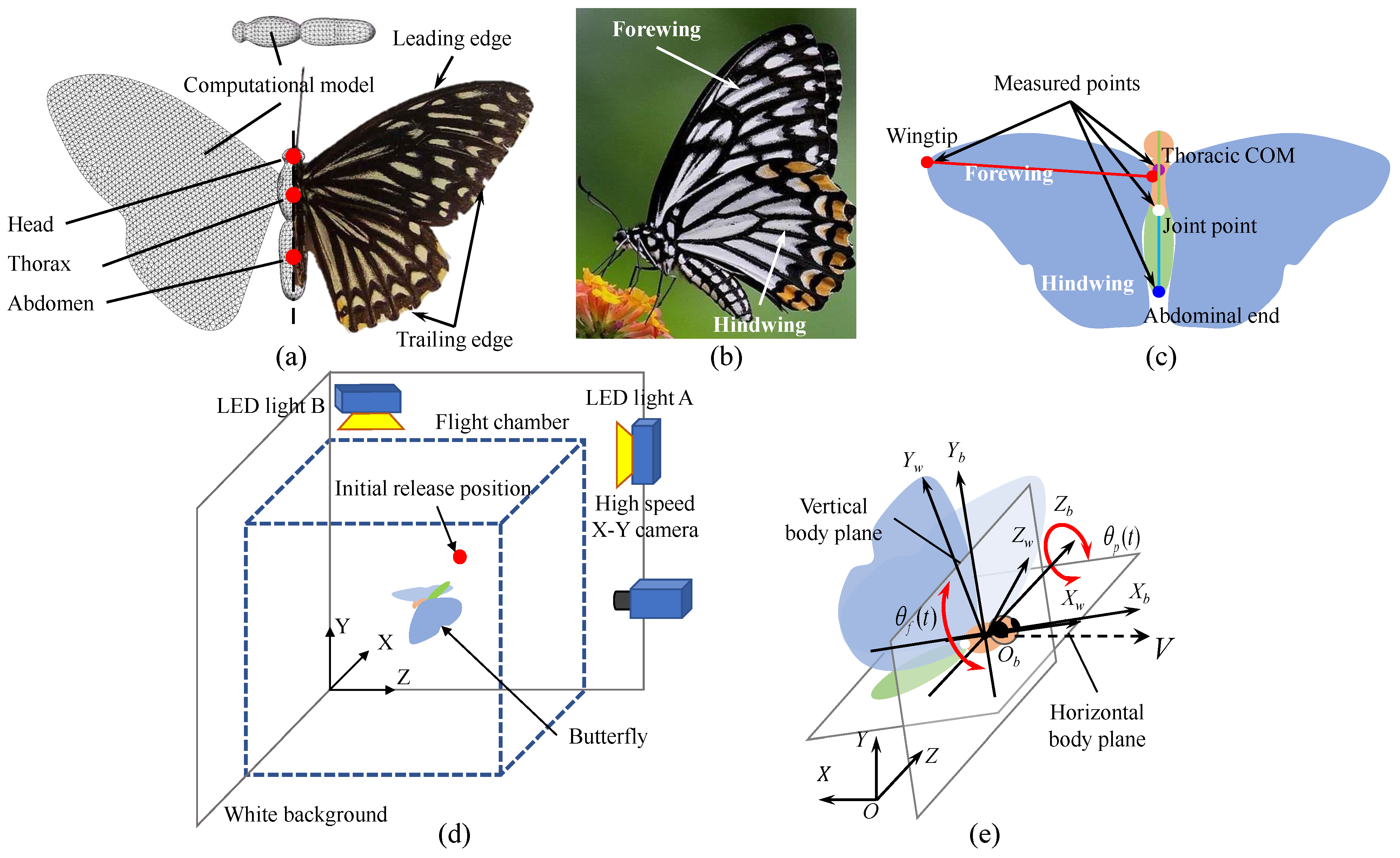
2.1. Materials and Equipment

To study the special flying skills of the butterfly, it is necessary to conduct detailed observation and quantitative analysis of the free flying state of the live butterfly. Chilasa clytia were collected from a breeding base in southern China. All adult butterflies are fed with fresh, rotten apples in the laboratory and kept active in a container with the temperature ranging from 25 to 32 °C and the humidity ranging from 40% to 70%.
Morphological parameters of the butterfly (Chilasa clytia) are summarized in Table 1, including the total mass ( m ) , the thoracic mass ( m t ) , the abdominal mass ( m a ) , the thoracic length ( L t ) , the thoracic width ( w t ) , the abdominal length ( L a ) , the abdominal width ( w a ) , the wings mass ( m w ) , the wing-tip length ( L t i p ) , the wing area ( 2 S w ) , the wing loading ( m g / ( 2 S w ) ) , and the chord length of the wing ( c ) . The mass of the butterfly is approximately 0.35 g. The wingspan ( S ) is about 8.29 cm, and its chord length is about 3.55 cm. The aspect ratio is expressed as AR = S / c . AR of the butterfly is about 2.3. The biomorphological characteristics of the butterfly are obviously different from other insects such as cockroaches, hawk moths, and bee flies.
Because the total mass of the live butterfly can be measured directly, the thorax masses and the wings subtracted from the total mass give the abdominal mass. Note that the actual value of the abdominal mass largely varies during the observation. The mass distribution of various body parts of the experimental butterfly is calculated. m t is similar to m a , and they account for about 30% of the total mass, respectively. m w accounts for about 15% of the total mass. Thus, it can be concluded that butterfly wings have very small surface mass density.
Compared with other flying insects, the butterfly has a larger physical size (the maximum span is more than 10 cm). Large flying space is required to ensure sufficient time to record the flight, so the transparent cube container made of grass with dimensions of 0.4 m × 0.4 m × 0.4 m is adopted. The flight velocity of the butterfly is high, and the frequency range of flapping motion is generally about 9–12 Hz. Therefore, enough light sources are arranged to increase the quantity of light entering the image sensor to ensure the sharpness of the image. The observation experiment system is shown in Figure 1d. The red dot is the initial release position of the butterfly, which is 30 cm high from the ground.
Two kinds of light sources are used in biokinetic observation. Light A is a QL-1000 LED continuum light source, and the output power is 1000 W, which is arranged in front of the cube container. Light B is OPT-FLP 125 mm × 103 mm surface light source, and the output power is 24 V/6 W, which is arranged directly above the cube container, to make sure the subject will not be shaded as much as possible. To observe the kinematic characteristics of various parts (abdomen, thorax, wing, etc.) in various flight states more clearly, the high-speed camera Motion BLITZ Cube4, which is made in Germany, is used for the biokinetic observation of butterfly. The frame rate is up to 93,000 fps (frames per second), and its output is black and white video. The resolution range of the captured image is 1280 (H) × 10 (V)–1280 (H) × 1024 (V) pixels. The shutter speed can be set to 2–1000 μ s.

2.2. Measurement and Calculation of Kinematics Parameters

2.2.1. Coordinate System of the Flight Kinematics

In this study, the Cartesian coordinate system is introduced to describe the wing and body kinematics of a butterfly. Three coordinate systems are applied to define the axis, the plane, and the characteristic angles related to the butterfly motion in Figure 1e: The first is the inertial coordinate system ( X , Y , Z ) ; its origin ( O ) is set at the initial center of gravity (COG), which coincides with initial release position. The X-axis is defined therein as the direction in which a butterfly moves forward, while the Y-axis is the direction opposite to that of gravity. The thorax rotation around the Z-axis is described with pitch motion, which is defined as the body pitch angle between the centerline of the thorax and horizontal plane (XZ plane). For instance, if the pitch angle is zero, the body will lie in horizontal plane; when it is 90°, the body will be vertical.
The body-fixed coordinate system ( X b , Y b , Z b ) is adopted to describe the body motion. The origin of the body-fixed coordinate system ( O b ) is set at the COG of the butterfly, which translates and rotates with the body. During the forward flight, the flight velocity of the butterfly is expressed as V, and the butterfly’s displacement is decomposable into two directions in the inertial coordinate system, the X- and Y-axis. The velocities in the X and Y directions are horizontal velocity v x and vertical velocity v y , respectively. The symmetry axis of the butterfly thorax is defined as the thorax axis, which coincides with X b -axis. The symmetry axis of the butterfly abdomen is defined as the abdomen axis. X b Z b and X b Y b denote the horizontal and vertical body planes, respectively. The abdomen rotates around the Z b -axis, and the angle is defined as abdominal swing angle.
The wing-fixed coordinate system ( X w , Y w , Z w ) is adopted to describe the wing-flapping motion. The motion of the wings is connected and simultaneous with the butterfly body in real flight. The origin of the wing-fixed coordinate system ( O w ) is set at the wing root and translates and rotates with the body. The butterfly flaps its wings around X w -axis, which is simplified to be parallel to the thoracic axis in this paper; the flapping angle is 90° when the two wings clap together.
The plane swept by the connection between the wing tip and the wing root during the fight is defined as the stroke plane of the butterfly wing. The angle between the stroke plane and the horizontal XZ plane is defined as β . In this study, the thoracic pitch angle, the abdominal swing angle, and the approximate flapping angle are denoted by θ p , θ a , and θ f , respectively. This paper mainly considers the longitudinal flight of butterflies, so the roll and yaw motions are ignored.

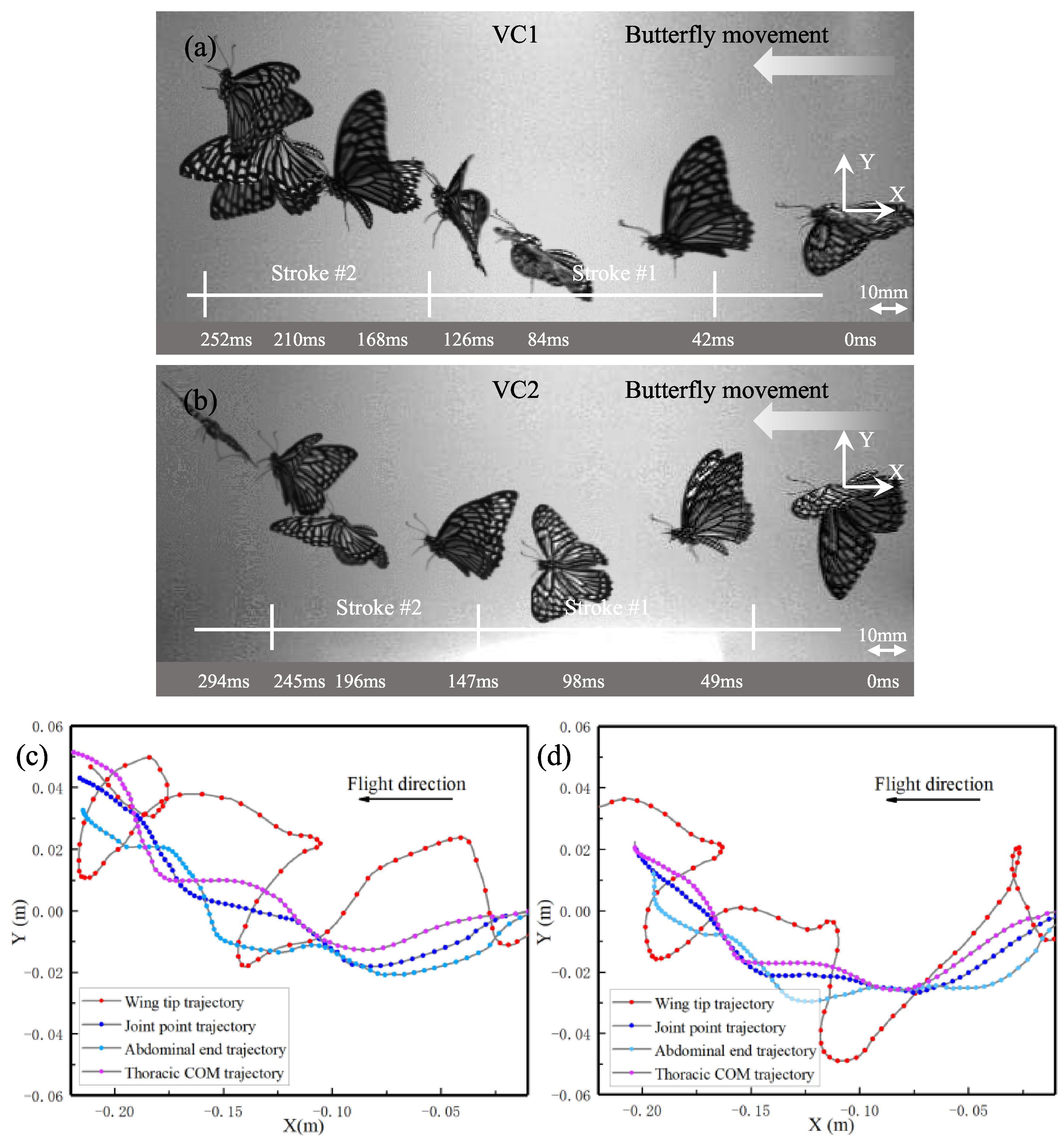
2.2.2. Movement Tracking of Butterfly Flight

We characterized and analyzed the motion and postures of the experimental butterfly flying horizontally in the cube container. The forward flight might be defined as translation horizontally in space. Because of the difficulty of recording the specific forward flight of a butterfly in the laboratory experiment, we redefined the forward flight such that the ratio between the vertical and horizontal translation of the COG is smaller than 0.15, d y / d x < 0.15, within a cycle. The wings and body movements were recorded with a high-speed camera and operated at the frame rate of 1000 fps with pixel size 1280 × 1024. To reduce the calculation amount of image processing for flight trajectory, the collected video is framed with pixel size 500 × 900 so that the calculation amount is reduced by about 50% and the processing time is reduced by more than half. The image-based feature point recognition method is utilized to track and analyze the motion.
The four feature points for the observation records of the spatial displacement are shown as purple thoracic COM ( x t , y t ) , white joint point ( x j , y j ) , blue abdominal end ( x a , y a ) , and red wingtip ( x w t , y w t ) in Figure 1c. The thorax axis and the abdomen axis are shown as solid green and light blue lines, respectively. Since the wing root is very close to the thoracic COM, the wing root and the thoracic COM are considered to coincide during the measurement. The joint angles of the thorax and abdomen during the free flight are observed. θ p and θ a are obtained from the geometric relationship, and numerical values of the feature points coordinates are derived as in Equations (1) and (2)
θ p = arctan y t y j x t x j .
θ a = arctan y a y j x a x j .
The finite difference algorithm adapts to calculate velocity and acceleration in the X-axis directions (the same with the Y-axis directions) is given by
v x i = x i + 1 x i 1 2 d t .
a x i = 2 x i + 2 x i + 1 2 x i x i 1 + 2 x i 2 7 d t 2 .
where v x i and a x i are the velocity and acceleration of the feature points in the X direction at frame i, respectively. x i is the position coordinate value of the feature point on the ith frame image. d t is the time interval between adjacent frames of the video. Then, the derived velocity and acceleration are low-pass filtered to remove noise. In the experiment, the instantaneous wingtip velocity was calculated as follows: V t i p = v x w t 2 + v y w t 2 , where v x w t and v y w t represent the velocity of the wing tip in the X and Y direction, respectively.

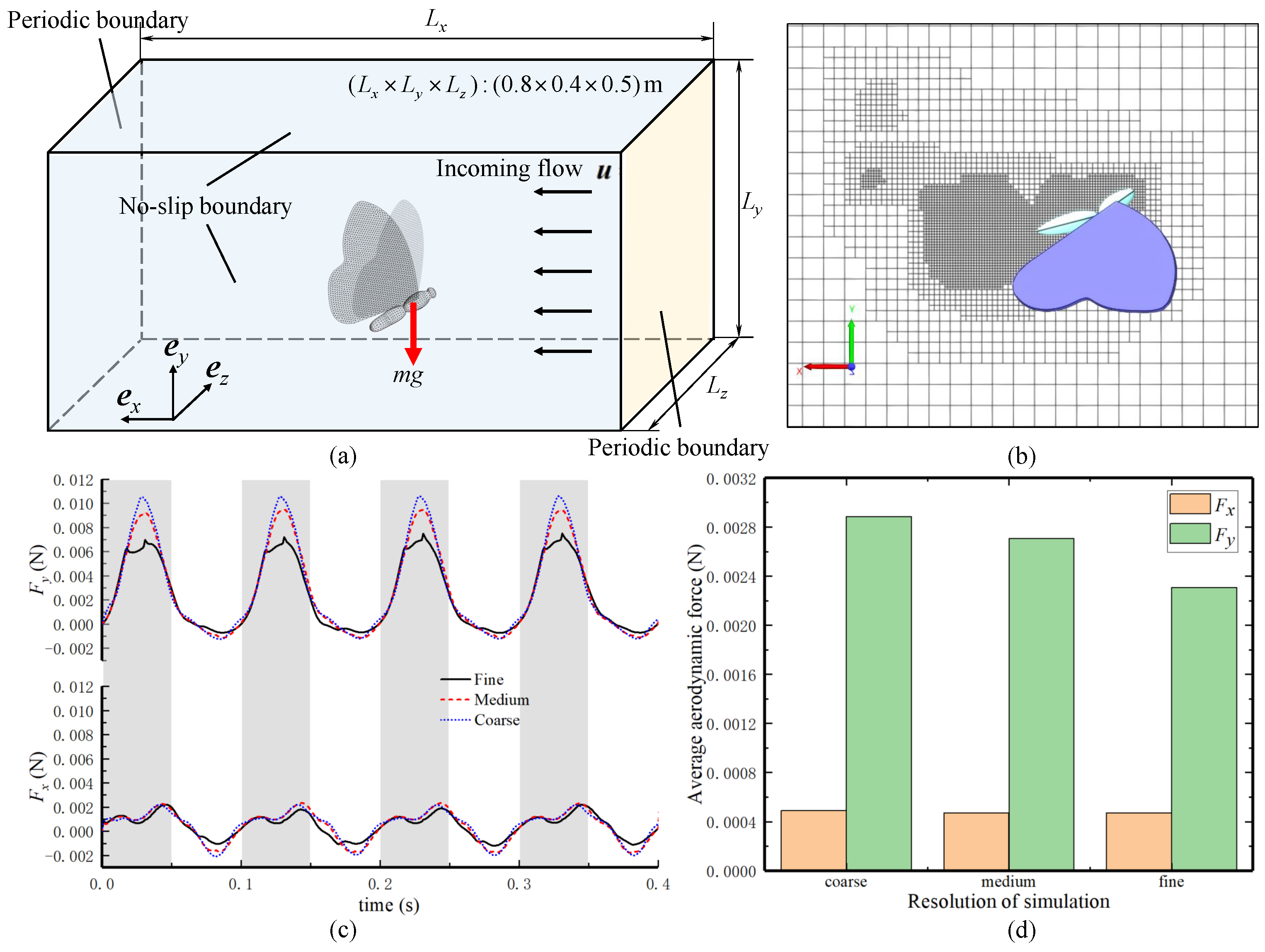
2.3. Computational Fluid Dynamics Simulation

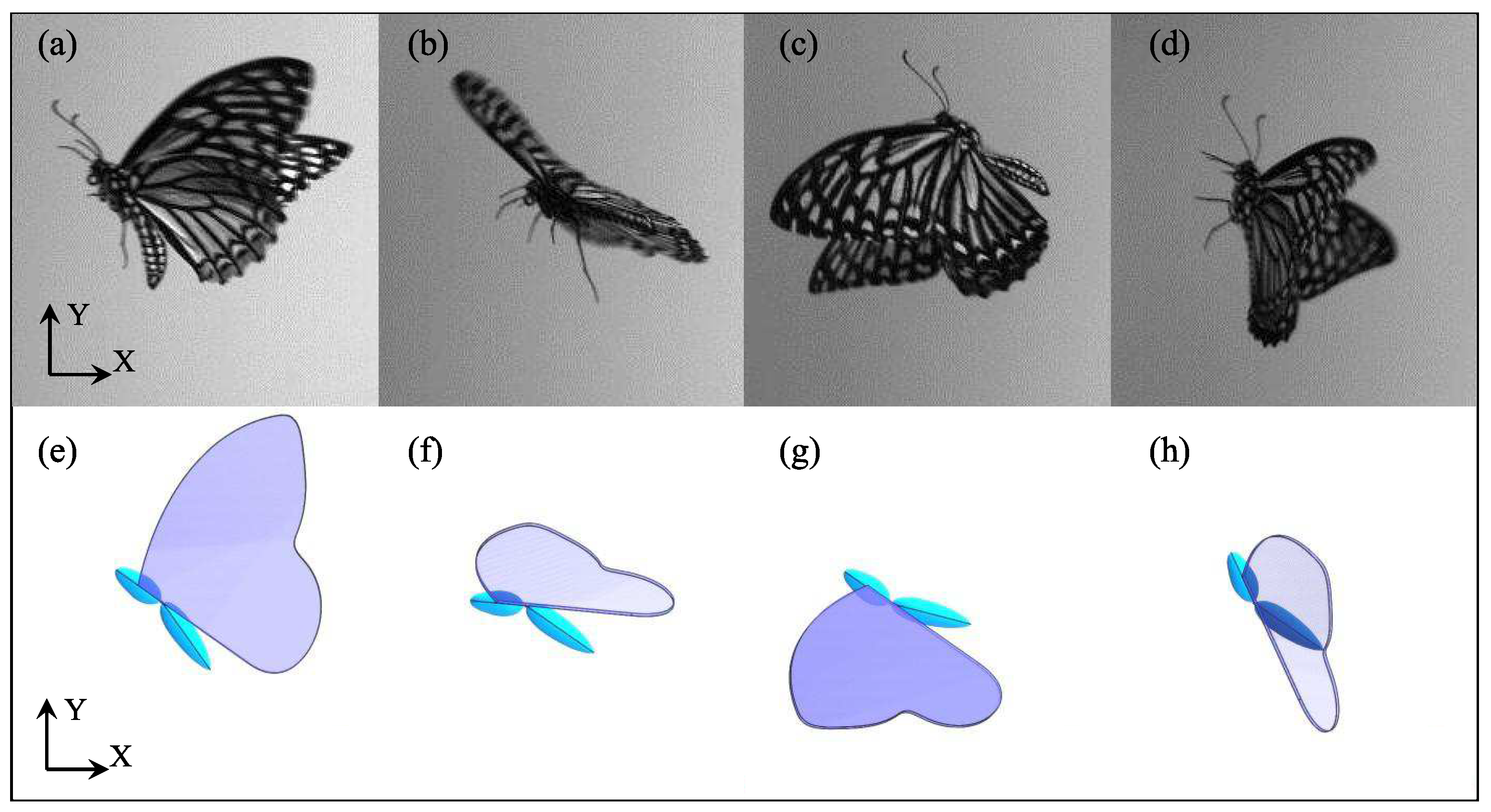
2.3.1. 3D Multi-Body Model of a Butterfly

There are a fore wing and a hind wing on each side of the butterfly body. To further simplify the model, the fore wing and hind wing are modeled as a unified wing. Figure 1a shows that the experimental butterflies (Chilasa clytia) consist of four parts, namely a spheroidal thorax, a spheroidal abdomen, and one pair of thin flat wings, and they are set as rigid bodies in the simulation. The thorax and abdomen are connected by joints with one degree of freedom (DOF). The thorax and left wing are connected by a joint with three DOFs, as are the thorax and right wing. The parameters of the real butterfly are used as the dimensions of the simulation model for CFD.
The wingspan and chord length of the simulation model is set to 8.5 and 3.6 cm. The positions of the leading edge and the trailing edge on the wings are shown in Figure 1b. Based on the two-dimensional images of a real butterfly, a simplified butterfly model is created. All parameters defining butterfly simulation model geometry are provided in Table 2.

2.3.2. Computational Setup for CFD Simulation

To clarify the influence of butterfly kinematics parameters on free flight, the CFD simulations are conducted in this paper. The direction of the mainstream is taken as the positive X direction, the vertically upward direction is taken as the positive Y direction, and the horizontal direction is taken as the Z direction. The directions are expressed by the Cartesian unit vectors e x , e y , and e z . The equations governing the flow field include an equation for the three-dimensional, transient, and incompressible continuity and the Navier–Stokes equation,
· u = 0
u t + ( u · ) u = 1 ρ a i r p + υ a i r 2 u .
where u is the velocity vector of the flow in the Cartesian coordinate system, defined as u = u 0 e x . p is the pressure. The fluid is considered to be 20 °C. The values of the air properties are adopted from those at 20 °C: the density of air ρ a i r = 1.205 kg/m3 and the kinematic viscosity υ a i r = 1.5 × 10 5 m2/s. It should be noted that the gravitational term does not appear in Equation (6). The velocity is constant on the inflow boundary plane: V , incoming flow velocity.
The streamwise length of the computational domain is L x = 0.8 m, which is approximately 20 times as long as the aerodynamic chord length. The boundary conditions of the flows are shown in Figure 2a. The periodic boundary condition is employed for the transverse boundaries, and, on the other sides, parallel to the longitudinal X-axis, the no-slip condition is used. The transverse length of the computational domain is L y = 0.4 m, L z = 0.5 m, which is approximately five times as long as the wing-tip length. The results are not affected by the values of L x , L y , and L z . The average wing-tip velocity V ¯ t i p equals the reference velocity defined as V r e f = 2 A f π r f / 180 ° . A f is the stroke amplitude, with the value about 120 ± 10°, f is the flapping frequency, r is the single wing length which equals L t i p / 2 . The governing parameter of the above equations is the Reynolds number ( Re ) given by
Re = V r e f L r e f υ a i r .
where L r e f is the reference length which is equal to c ¯ . c ¯ is the mid-chord length (2.5 × 10² m). It should be noted that the definition of the Re is the same as that used in [2,31].
In this simulation case, the Re during butterfly forward flight is about 3000. Two key parameters of the flapping wing propulsion are the Strouhal number [32] and the advanced ratio, which are defined as S t = 2 L r e f f / V and J = V / V r e f , respectively. Set V to 1 m/s, f = 10 Hz, V r e f = 1.75 m/s, S t is about 1.75, and J is about 0.57. Three-dimensional flow fields were characterized with the isosurface of the vorticity ω , so that the vortex structures of the butterfly are identified.
The aerodynamics model of the butterfly is simulated numerically with the Lattice Boltzmann method (LBM) [33], which is applied with a commercial LBM code: Next Limit Technologies’ XFlow. Unlike traditional CFD software, XFlow provides a proprietary fully Lagrangian particle-based kinetic solver, which dramatically reduces the time to calculate for a given level of solution accuracy. The LBM proves to be efficient and reliable for aerodynamic force, torque, and vortex wake structure simulation under various conditions [34,35,36]. The kinematic law of the butterfly is adapted to the multi-body model by the kinematic simulation software (ADAMS). Firstly, the three-dimensional model of the butterfly is established in the modeling software Solidworks. Then, the model is imported into ADAMS. In ADAMS, kinematics rules for the rigid body parts are supplemented and then the “.res” file is generated. Finally, the three-dimensional model and motion rule file of the butterfly are imported into XFlow. The fluid conditions can be set and then carry out simulation data analysis.
The spatial resolution of the far field (Resolved scale in XFlow) is set to be the largest level of the lattice in adaptive refinement mode. The smaller the resolved scale is, the more accurate the numerical calculation is. The simulation time also increases with the number of elements being calculated. The resolution of the near wall is set to smallest to refine dynamically moving geometries. The dynamic domain topology will perform octree stratification according to the several resolution settings to get the ideal computational lattice, as shown in Figure 2b. The resolution of the wake is set to the same value as the resolution of the near wall for getting the clear wake flow.
In this study, the time step of each flight case is set to 0.001 s, and the resolution scheme is carefully selected, as shown in Table 3. Note that “s” represents the initially tested resolution. Figure 2c,d shows the comparison of aerodynamic forces during the four flapping strokes from three resolution set-ups (coarse, medium, and fine). The differences of the average values of the horizontal and vertical aerodynamic forces between the medium-resolution (adopted in this paper) and the fine-resolution are about 2% and 10%, respectively. In XFlow, it is necessary to ensure that the stability parameter of the simulation is low, and the relatively fine domain structure can be obtained. Considering the calculation time and accuracy, the medium-resolution scheme of s/2 is chosen as the simulation condition.

2.3.3. Mathematical Kinematics Model for Forward Flight

The flight motion of the butterfly mainly couples the motions of the wing flapping and the thorax pitching. The abdominal motion, which actively changes the pitch Angle of the thorax, is important for the stability of the flight. By pitching the body, the butterfly manipulates the stroke plane angle to adjust the direction of the flapping motion. The movement of wings is accompanied by clapping and peeling during the downstroke (DS) and upstroke (US), respectively.
The flapping motion and the pitch motion of the real butterfly and the simulation model change periodically, as shown in Figure 3. The swing of the abdomen directly affects the pitch angle of the butterfly thorax. Thus, the wing kinematics can be expressed as the flapping motion θ f ( t ) , the pitch motion θ p ( t ) , and the phase difference γ between θ f and θ p .
The wing and body kinematics of four consecutive flapping cycles were recreated with our programs. To input the flight kinematics model of butterflies recorded from observation into a simulation, three cosine wave functions served to approach the flapping motion and pitch motion the same as in the experiment. The functions are expressed as
θ f ( t ) = A f cos ( 2 π f t ) + A 0 θ p ( t ) = A p cos ( 2 π f t + γ ) + B 0 θ a ( t ) = A a cos ( 2 π f t ) + C 0 .
in which A f , A p , and A a are the amplitudes of θ f ( t ) , θ p ( t ) , and θ a ( t ) from the experiment. The aerodynamic forces are calculated with mathematical sets of the kinematic parameter K ( f , A f , A p , A a , A 0 , B 0 , C 0 , γ , V ) . The observed results show that A f of the wings is about 60.0°; A p of the thorax is about 30.0°; and A a of the thorax is about 20.0°. γ is the phase difference between flapping and thoracic pitch motion about π / 2 rad or smaller. The initial flapping angle A 0 of the wing in the balanced position is approximately 20°. B 0 is the initial pitch angle in the balanced position, approximately 34° in the simulation. C 0 is the initial abdominal swing angle in the balanced position, which is approximately −35°. The lead-lag angle of the wings is approximately 15°, which is determined by a three-dimensional model. To clearly describe the kinematics of the butterfly during flight, non-dimensional time is defined as t ^ = t / T , T is the flapping period. Thus, the initial kinematic simulation equation can be obtained as follows.
θ f ( t ) = 60 ° cos ( 2 π f t ) + 20 ° θ p ( t ) = 30 ° cos ( 2 π f t + π 2 ) + 34 ° θ a ( t ) = 20 ° cos ( 2 π f t ) 35 ° .

3. Results

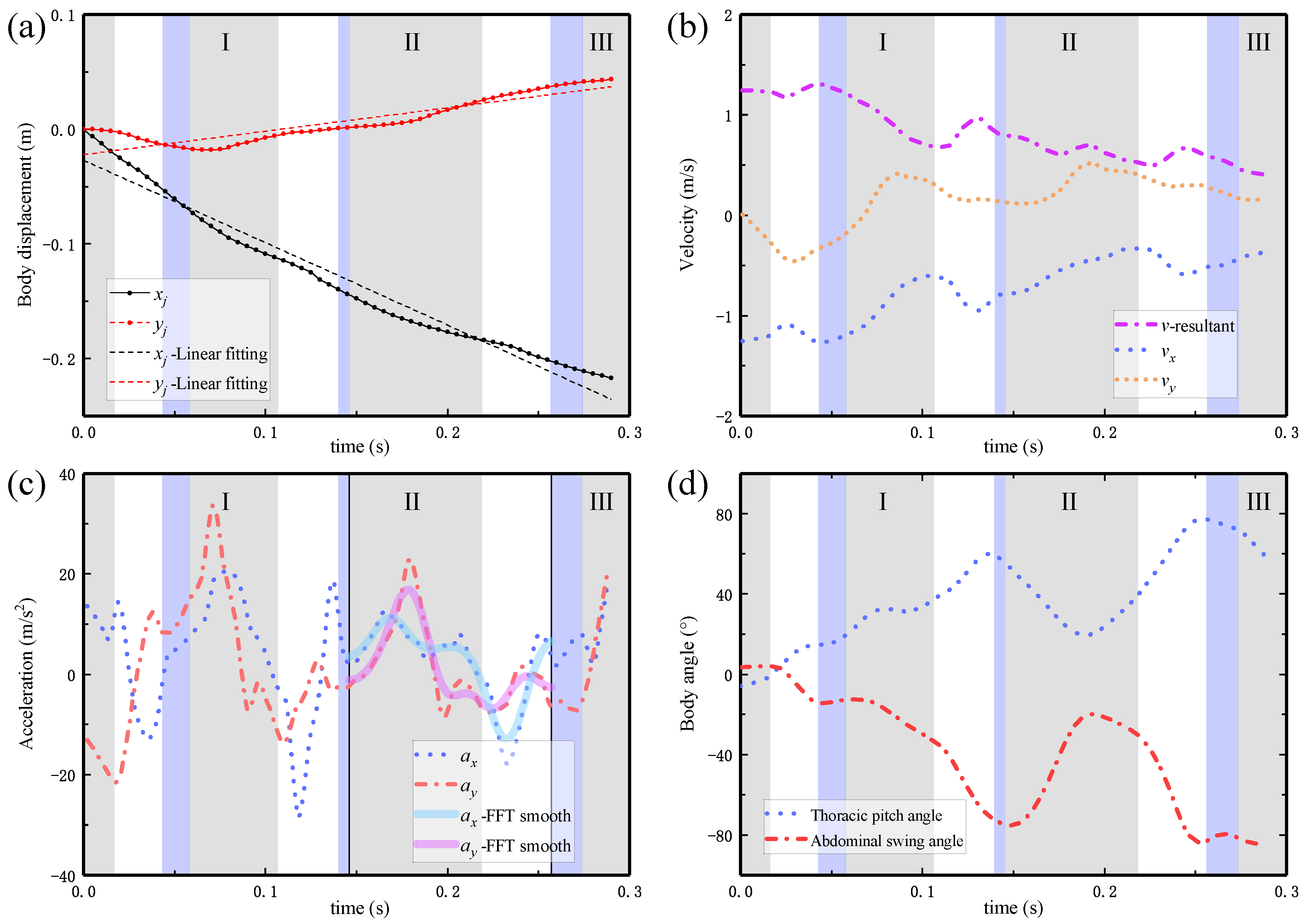
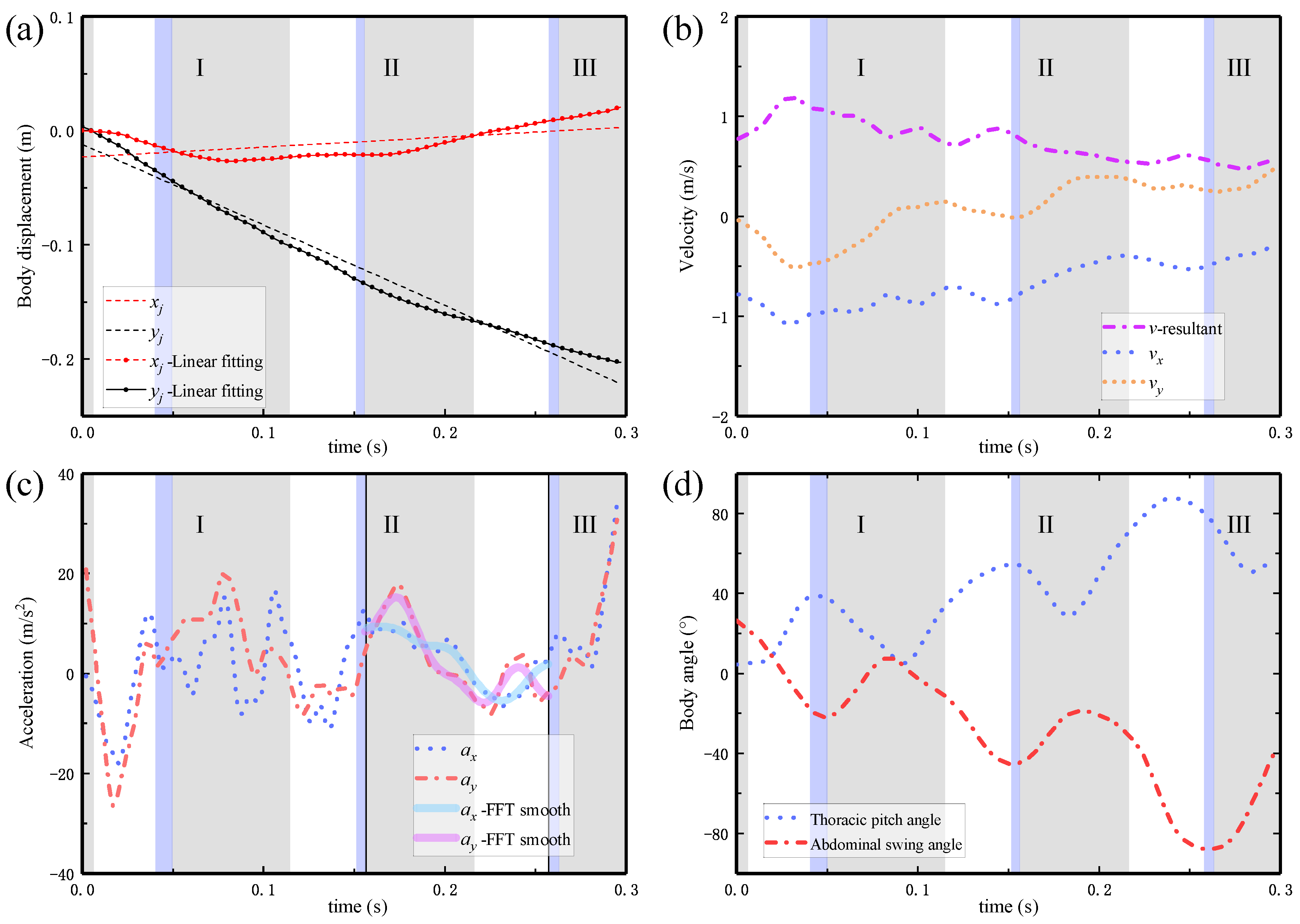
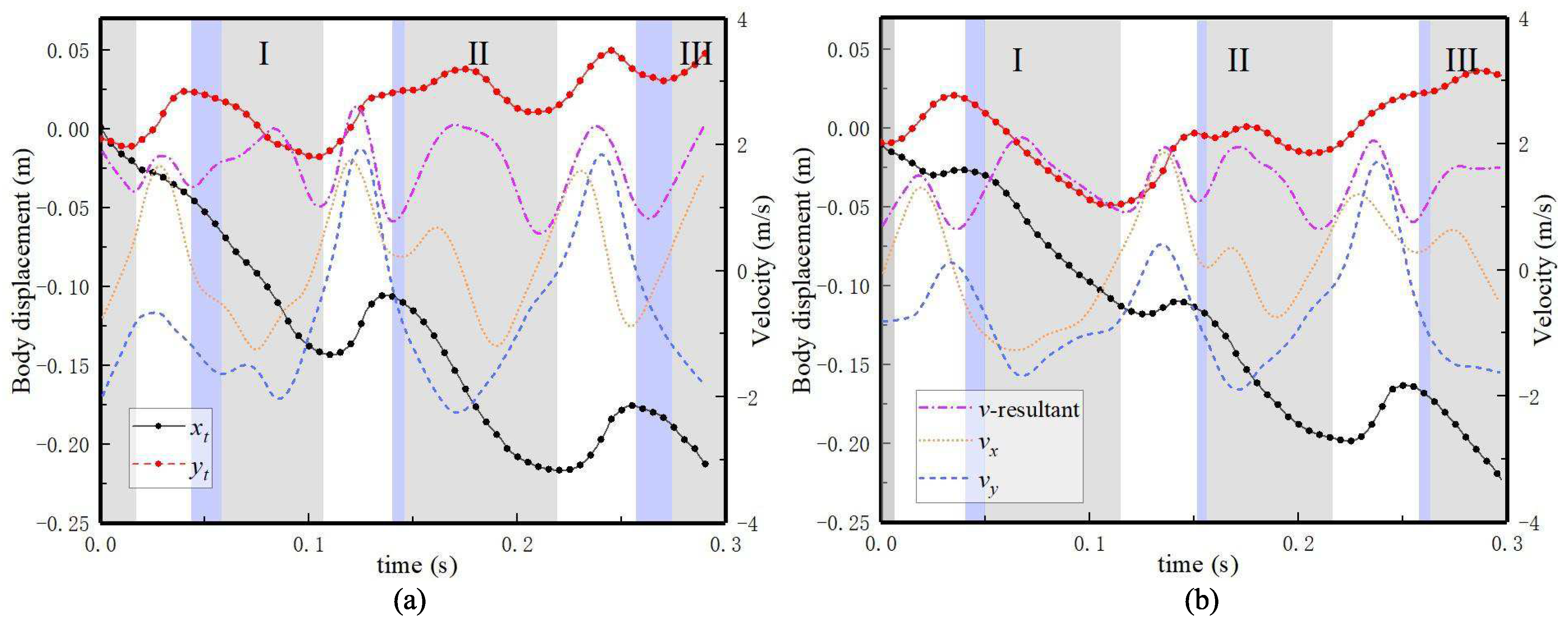
3.1. Wing and Body Kinematics of Butterfly Forward Flight

Our aim in this paper is to present the clearest forward flight and reveal the special flying skills of the butterfly (Chilasa clytia). Ten videos of the butterfly free flying about 300 ms long were filmed. Two of them were selected as the two cases (denoted as VC1 and VC2) of forward flight because the displacement of the butterfly centroid in the X-axis and Y-axis directions satisfied d y / d x < 0.15.
For the two cases, the analyzed kinematics results of the butterfly are shown in Table 4, including the total time of forward flight ( t total ) , the average stroke amplitude ( A ¯ f ) , the average flapping frequency ( f ¯ ) , the average pitch angle ( θ ¯ p ) , the maximum pitch angle ( θ p max ) , the minimum pitch angle ( θ p min ) , the average abdominal swing angle ( θ ¯ a ) , the maximum abdominal swing angle ( θ a max ) , and the minimum abdominal swing angle ( θ a min ) . Two complete flapping cycles were intercepted from the two videos, named Stroke #1 and Stroke #2, which correspond to the subscript numbers, respectively.
For each of the flights, the recordings of 2–3 wing flapping cycles were digitized. Snapshots of a butterfly in forward flight VC1 and VC2 from the front-view camera are shown in Figure 4a,b, respectively. Because the displacement along the Z-axis is very close to zero throughout the entire process of forward flight, only the displacements along the X-axis and Y-axis are plotted. The coordinates at 0 ms are set to (0, 0, 0).
Figure 4c,d shows the trajectory of the butterfly feature points during the forward flight (space trajectory curve and body trajectory curve) recorded using high-speed photography, respectively. It can be seen that the body and wings of the butterfly have obvious oscillations during flight.
After tracking all the feature points based on all recorded frames, the displacements and kinematic curves of the butterfly in the relative coordinate system were obtained from VC1 and VC2 and plotted in Figure 5 and Figure 6, respectively. All the stroke moments were also labeled. Grey shading indicates the DS, while white shading denotes the US. The purple shading indicates the gliding flight from the end of the US to the beginning of the next flapping cycle. After being released from the initial release position, the butterfly first flaps its wings slightly for one or two strokes with a small reduction in flight altitude, and its average flight speed increases accordingly; then, the average pitch angle increases, which is equivalent to an increase in the angle of attack of the body. The butterfly starts to climb, and its average flight speed decreases accordingly.
The vertical acceleration ( a y ) reaches the maximum value at the mid-downstroke of the DS, at which time a lift peak appears, and almost no lift is generated during the US. For almost the entire downstroke, a y is positive because the instantaneous vertical aerodynamic force of the butterfly is lift, while the horizontal acceleration ( a x ) is positive because the instantaneous horizontal aerodynamic force is drag. a x reaches the maximum value at near the mid-upstroke of the US, at which time a peak of the thrust appears. The kinematics analysis result shows that the phase difference between butterfly flapping motion and pitching motion is close to π / 2 . Under different flight conditions, the phase difference between the pitch angle and the swing angle varies greatly, which is about π in our observation.
The observation analysis of wing tip kinematics is shown in Figure 7. The maximum velocity of the wing tip is reached when the wings reach mid-downstroke or mid-upstroke position during flapping downward or upward, respectively. v x w t and v y w t change periodically with flapping motion. The maximum and minimum values of the resultant velocity of the wingtip in VC1 are 2.6 and 0.6 m/s, respectively. The average resultant velocity of the wingtip is 1.6 m/s. Similarly, the average, maximum, and minimum resultant velocity of the wingtip in VC2 are 1.4, 2.1, and 0.6 m/s, respectively.
During the flight, the glide flight mode is used to reduce flight energy consumption. This mode often appears between the end of the upper flap and the beginning of the next flapping cycle. At this time, the wings are almost closed on the back, the projection area in the flight direction is the smallest, and the air resistance is also small. Therefore, the main body has a certain height drop during the gliding process due to its own inertia, and the flight velocity will increase accordingly. Due to the unstable flight of the butterfly, it is difficult to capture the state of the butterfly’s continuous forward flight under free flight conditions. In this experiment, the butterfly is released from a fixed position to guarantee that the butterfly’s head faces the X direction of the space.
For VC1 and VC2, the flying behaviors of the experimental butterfly are similar. After the butterfly is released, it accelerates to fly forward in the initial stage, and the velocity and flight trajectory have fluctuation characteristics with the same frequency as the flapping motion. When the flight speed increases, the amplitude of the abdominal swing and the average swing angle increase, with the increase of the average pitch angle of the body. Obviously, the upper and lower limit angles of the pitch movement both increase, as shown in Figure 5d and Figure 6d. At the end of the videos, the butterfly has completed the efficient climb flight. In summary, the flight of a real butterfly is complex and unstable, and detailed measurement and analysis of its kinematic parameters under different flight conditions are very meaningful. In the following, the CFD method is used to quantitatively analyze several key kinematic parameters that affect butterfly flight performance.

3.2. Effect of Kinematic Parameters and Computational Fluid Dynamics Simulations

In the simulation, the flapping frequency of the butterfly is set to 10 Hz. The aerodynamic force generated by flapping wing at a certain inflow velocity can be obtained through simulation analysis. It displays the overall forces ( F x , F y , F z ) , in global axes, exerted by the fluid on the entire geometry model and the corresponding force coefficients ( C x , C y , C z ) :
C x = F x 0.5 ρ V r e f 2 A r e f C y = F y 0.5 ρ V r e f 2 A r e f C z = F z 0.5 ρ V r e f 2 A r e f .
where F x and F y are the instantaneous horizontal and vertical aerodynamic force in downstroke and upstroke, respectively. When F x is negative, it indicates thrust; when F x is positive, it indicates resistance. F ¯ x and F ¯ y are defined as the average horizontal and vertical aerodynamic force ( F ¯ a e r o = 1 T t t + T F a e r o ( t ) d t ) , respectively. The vertical force is the lift force, while the horizontal aerodynamic force is the the resultant force of thrust and resistance. A r e f is the reference area which equals the projected area of the wing. S w is the area of one wing.
The kinematic parameters in Equation (8) would change regularly to reveal the effect of the kinematics model on butterfly flight. Different pitch motions may affect the flying velocity of the butterfly, while the fixed flying velocity is considered here. Based on previous observations and combined with empirical analysis, the initial kinematic simulation model can be obtained as Equation (9). Four kinematic parameters including B 0 , V , γ , and A f with greater influence on butterfly flight were selected as research content. To verify the ideas proposed in the experiment, the following four cases are simulated and analyzed. All simulations start flapping downward from the upper limit position. The four cases of set-ups are shown in Table 5.

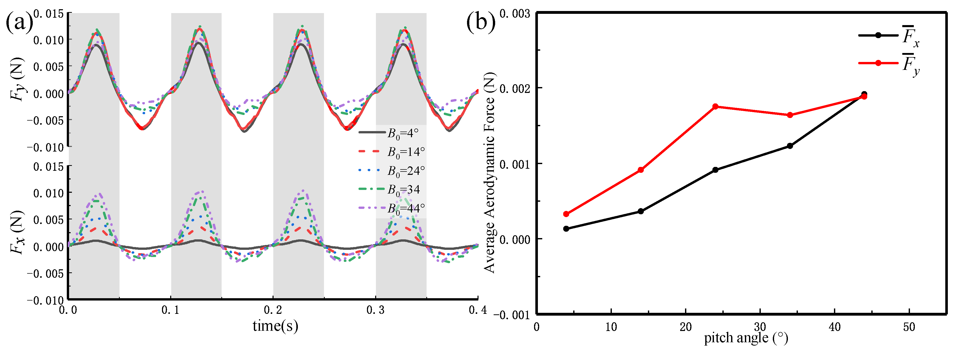
3.2.1. Effects of the Thoracic Pitch Angle (Fixed)

First, Case 1 is simulated as the free flight without rotation. Otherwise, attitude control is assumed to be perfectly achieved and does not affect the translational motion of the body. The incoming flow velocity is set to 1 m/s according to the actual flying velocity of the butterfly in the horizontal direction.
In this case, the thoracic pitch angle is a fixed value ( θ p ( t ) = B 0 ) to verify that body pitch is necessary for the flight. Moreover, this means that the body of the model does not rotate in the pitching direction and the yawing and rolling directions. B 0 is taken as 4°, 14°, 24°, 34°, 44°. The simulation results are as follows (Figure 8).
Under the condition that the pitch angle value is small ( θ p = 4°, 14°), the positive and negative peak values of the lift generated by flapping are basically equal in magnitude, and the drag is relatively small. As the pitch angle increases within a certain range, both the positive peak value and the mean value of the lift increase. In comparison, the resistance increases during this period because of the increase in the average windward projection area of the butterfly. In summary, the case with a fixed pitch angle (without wings rotation) shows that the maximum average lift of the butterfly is less than 60% of the butterfly’s gravity. Thus, the pitching motion of the body is extremely necessary for butterfly flight.

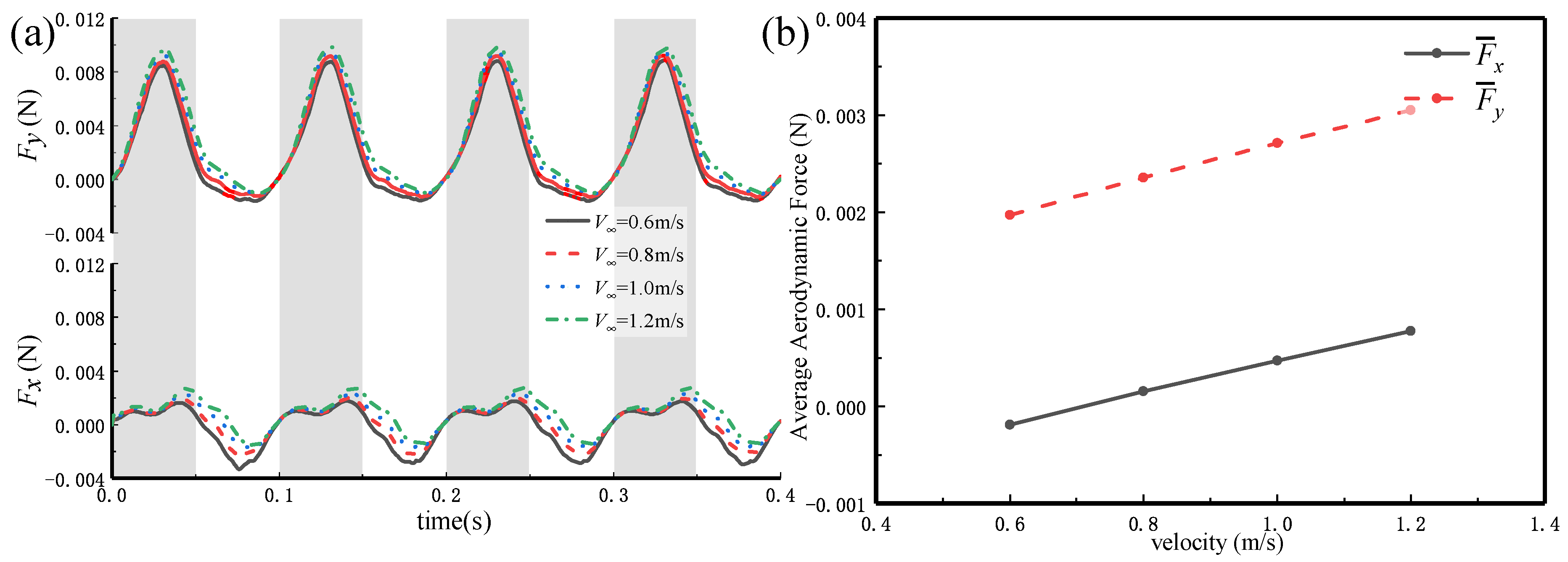
3.2.2. Effect of the Flight Velocity in Forward Free Flight

This simulation aims to investigate the effect of kinematics parameters of the model with rotation in addition to the translational motion. In Case 2, V is taken as 0.6, 0.8, 1.0, and 1.2 m/s. A kinematic parametric study on flight velocity is presented to explore its influence on aerodynamic performance. We simulate free flights of the butterfly model with rotation (body pitch motion). The kinematics of thoracic motion is simplified to a time-varying cosine function. The initial position and amplitude of the thoracic pitch angle are certain values. The simulation model of the body can rotate in the longitudinal direction, while it does not rotate in the yawing and rolling directions. The simulation results are shown in Figure 9.
As the velocity increases, the lift and drag generated by flapping wing increase synchronously, and their instantaneous peaks increase accordingly. F ¯ x and F ¯ y of the butterfly at the velocity of 1.0 m/s are 4.7 × 10 4 and 2.7 × 10 3 N (approximately 80% of butterfly gravity), respectively. The lift reaches the instantaneous maximum 9.5 × 10 3 N at the mid-downstroke of the DS (approximately 0.025–0.03 s). The thrust reaches the instantaneous maximum 1.7 × 10 3 N at the mid-downstroke of the DS (approximately 0.075–0.08 s). The effect of flight velocity on lift and drag is relatively linear within the test velocity range. According to previous kinematic observations, the butterfly has fluctuations in the Y-axis direction, and the velocity in the X-axis direction is also time-varying. v x and v y will be set as a periodic change function in further research.

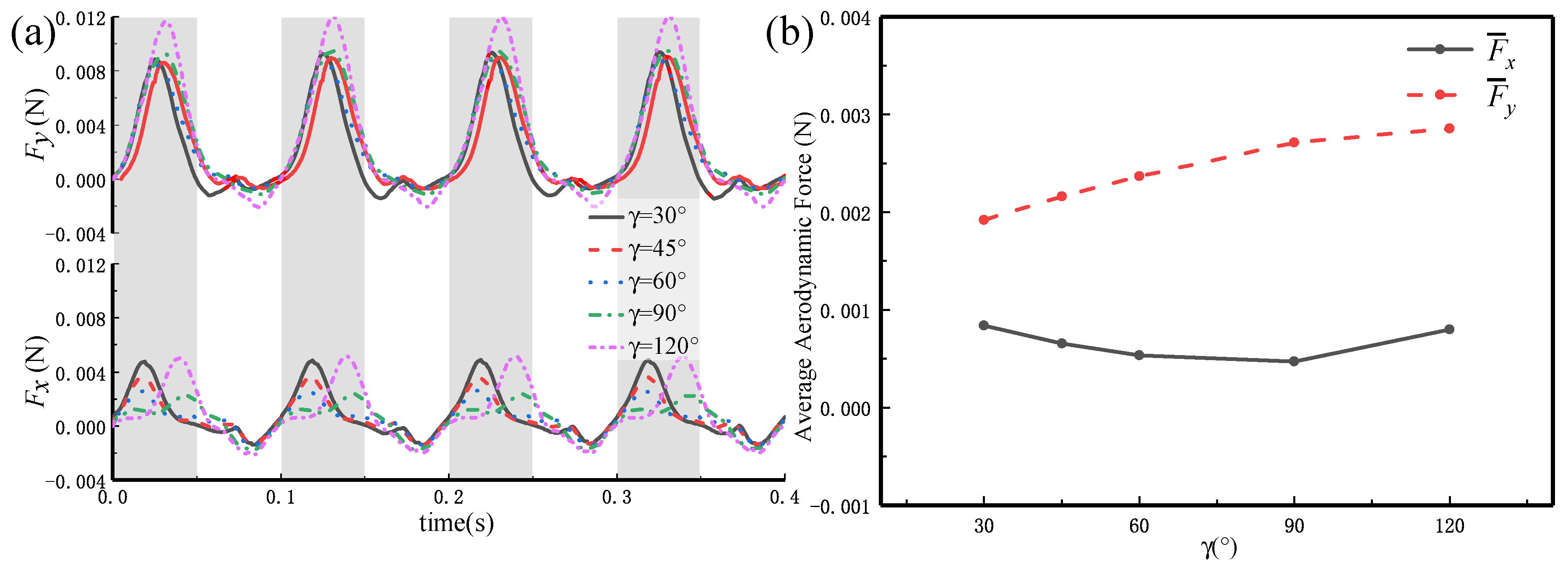
3.2.3. Effect of the Phase Difference between Flapping and Thoracic Pitch Motion

The coupling of the butterfly body and wings is considered in Case 3. γ is taken as π / 6 , π / 4 , π / 3 , π / 2 , and 2 π / 3 . The simulation results in Figure 10 show that the lift generated by flapping wing always increases, but the drag decreases first and then increases as γ increases. when γ π / 2 , the generation of the drag peak is postponed backward, and the generation time is shifted by about 0.02 s compared to the smaller γ . F ¯ x and F ¯ y of the butterfly ( γ = 2 π / 3 ) are 8.0 × 10 4 and 2.9 × 10 3 N, respectively. The lift reaches the instantaneous maximum 1.2 × 10 2 N near the mid-downstroke of the DS (approximately 0.03–0.035 s). The thrust reaches the instantaneous maximum 2.1 × 10 3 N near the mid-upstroke of the US (approximately 0.08–0.085 s).
To achieve forward flight, the butterfly needs to have a certain thrust (low resistance) to get sufficient lift. That is, it is necessary to choose a suitable kinematic parameter γ .

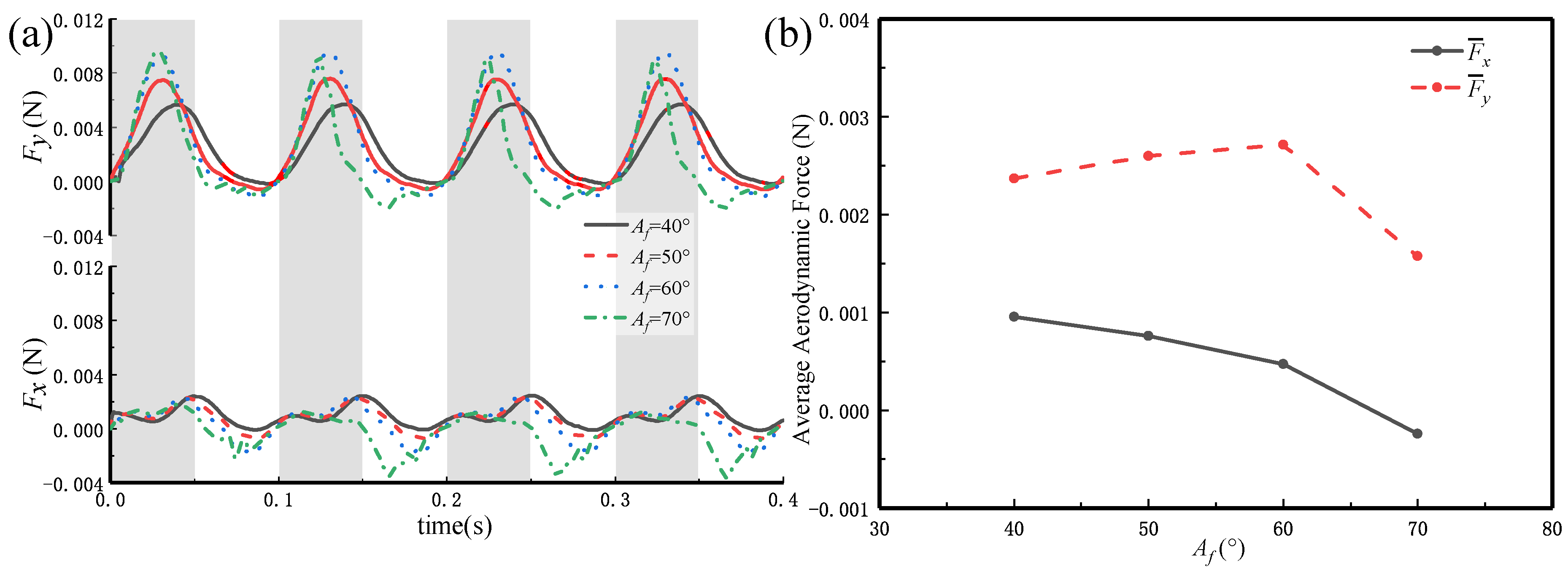
3.2.4. Effect of the Flapping Angle in Forward Free Flight

In Case 4, different wing-flapping motion amplitudes are shown: the flapping balance position is determined, while the upper limit and the lower limit positions during flapping are different. The incoming flow velocity, in this case, is set to 1 m/s. The kinematics rules are set by ADAMS.
Figure 11 shows that the appearance of the peak of the lift and thrust is advanced in time, and F ¯ x of the butterfly gradually decreases as the flapping angle increases. That is, the resistance decreases, and thrust increases. It is worth mentioning that the lift force increases with the increase of the A f within a small amplitude range, but, when it is increased to larger than a certain angle ( A f = 60°, in this study), the lift force suddenly decreases to less than 50% of gravity. Thus, it is not that the larger is the A f , the greater is the average lift. The result reveals that the butterfly has a relatively large average lift (close to the butterfly’s gravity) when A f is 60°, consistent with the observation results. The butterfly needs to determine the amplitude of each flapping according to the different lift requirements.

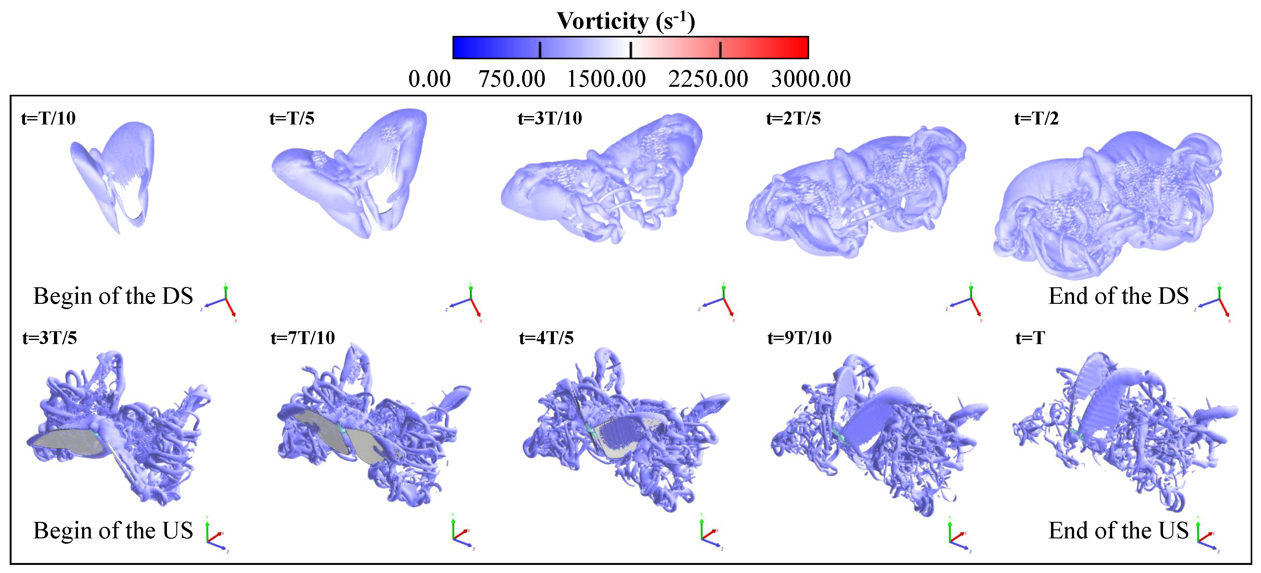
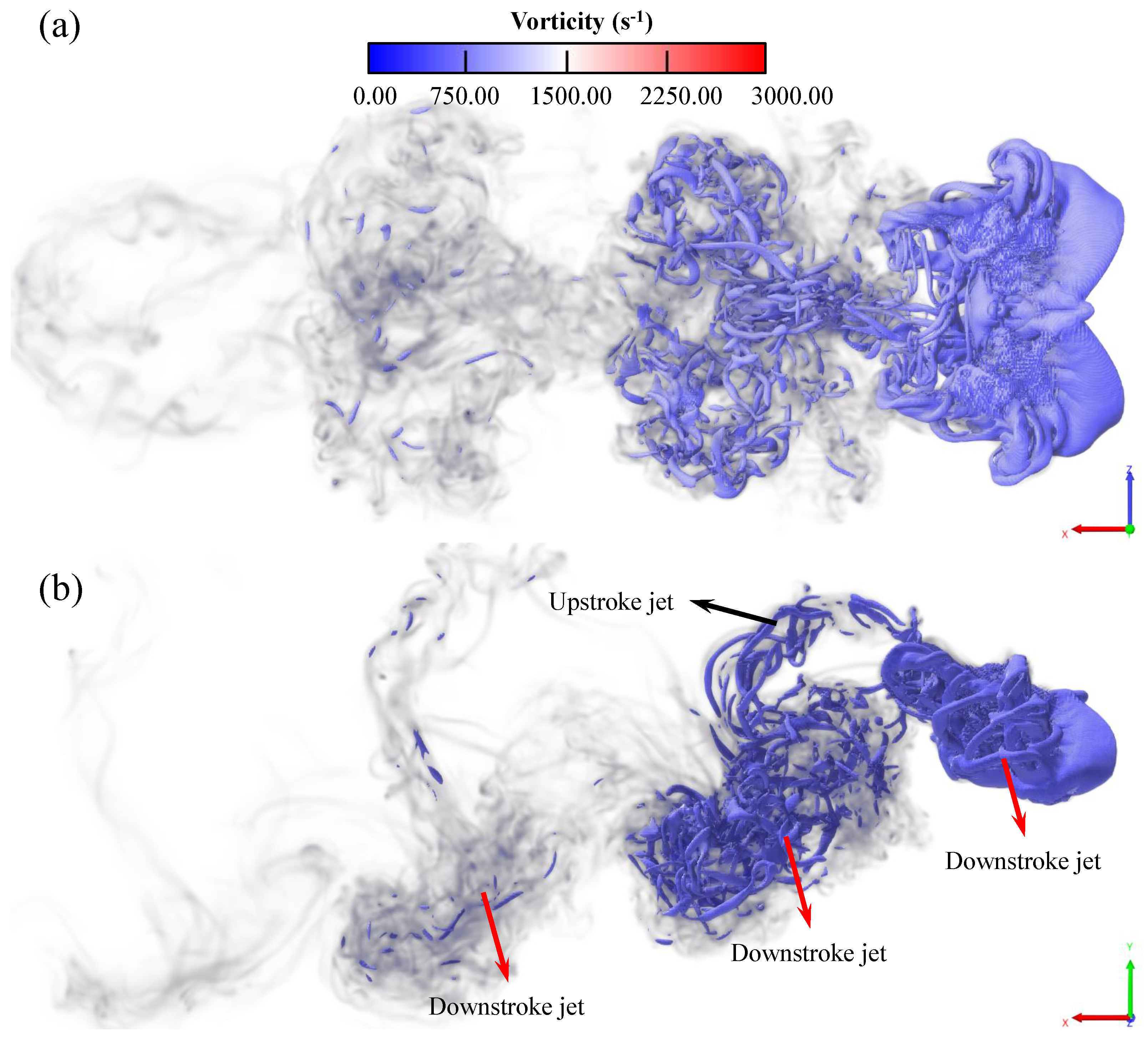
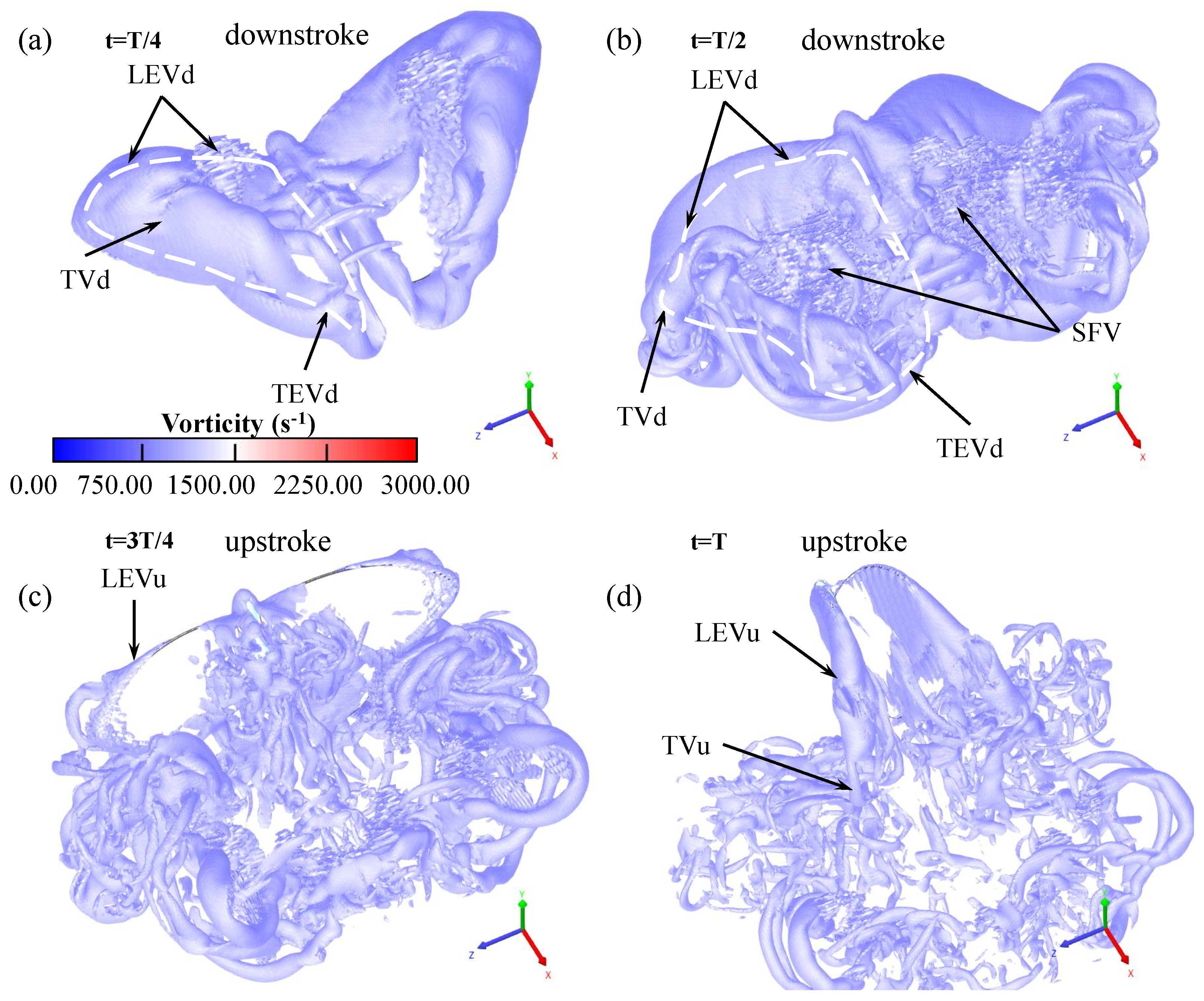
3.3. Vortical Structure during Forward Flight

3.3.1. Vortex Formation and Development

The butterfly uses the chest muscles to drive the wings to stir in the viscous air. The air around the wings generates vortices, which in turn generate enough lift to overcome its own gravity. When the wings flap downward, the body floats upward. When the wings flap upward, it mainly generates thrust to fly forward. The formation and development of 3D vortex structures in one flapping cycle of forward flight are presented in Figure 12. Leading-edge vortex (LEV) and wing-tip vortex (WTV) appear on the dorsal side of the wings, and they are connected at the corner of the wings. The trailing edge vortex (TEV) is also clear during the downstroke. The two kinds of LEVs are reported in hawk moth’s hovering flight [37]. As a real butterfly, WTV and LEV are a major cause of the lift and thrust generation of the model. During the DS, the airflow flows upward from the leading edge to the dorsal side of the wings, forming a tube-type vortex over the entire leading edge of the wings (from the wing root to the wing tip) [38]. This vortex is a conical spiral along the direction of the leading edge. This spiral vortex is small at the wing root but larger at the wingtip.
Figure 13 shows the detailed butterfly vortex structures overlapping the vorticity volumetric field during free forward flight under the kinematic parameter K (10 Hz, 60°, 30°, 20°, 20°, 34°, −35°, π / 2 , and 1 m/s) in four flapping cycles. Large-scale zigzag structures of the tracer density caused by the upstrokes and downstrokes are observed both by the numerical simulation and in the experiment. This is mutually supported by the results in [39], as shown in Figure 13b. During the DS, the wings of the butterfly will produce a slanting downward jet. The reactive force of the jet against the butterfly can overcome the butterfly’s own gravity. The wake formed by every flapping stroke is mushroom-shaped from the top view (Figure 13a).
At the same time, during the DS, the entire vortex remains parallel to the leading edge of the wings, and is close to the leading edge without detaching (Vortex shedding). From the wing root to the wing tip, the Leading-edge vortex during the DS (LEVd) gradually weakens, disappears, and then is replaced by another newly generated vortex named wing-tip vortex during the DS (WTVd). After the vortex moves to the tip of the wing, it is twisted with the airflow at the wing tip from the ventral surface of the wing and then extends to the tail of the butterfly, so that the cyclones generated by the flapping motion of the two wings form a vortex ring.
Every time the butterfly flaps its wings downward, a vortex ring forms at the leading edge of the wings, and then it rushes out of the cyclone during the US. The separation on the leading edges makes complex secondary flow vortices named secondary flow vortex (SFV) below the LEVd [39]. At the start of the US, the small vortices form and attach near the thorax and wing root. At the end of the upstroke, a relatively small vortex ring forms on the ventral side of the butterfly wings near the leading edge and the wing tip, and the thrust peak appears simultaneously. Figure 14 shows the exquisite 3D vortex structures in the butterfly forward flight. Each DS, a strong oblique downstroke jet is generated, indicating the generation of the lift. A relatively weak oblique upstroke jet will be generated when it flaps the wings upward, and this indicates the generation of the thrust, as shown in Figure 13b. The aerodynamic simulation results of the free flight of the butterfly (Kallima inachus) in [40] support the research of this article.
Flight experiments have proven that this vortex created a low-pressure area over the wings of the insect, such as cicada in [41]. Under the impetus of the surrounding high pressure, the wings in the center of the low-pressure area will be attracted to rise. Each low-pressure area will be held up by the surrounding high-pressure area so that insects in the low-pressure area will get a lift.
Previously, aerodynamicists suspected that leading-edge vortices generated by insects’ vibrating wings could get enough rising power because they did not see the details of the vortices and were conservative. The researchers believe that the significance of this discovery is that, for the first time, the vortices at the leading edge of the insect’s wings have been spiraled, conically advancing from the wing root to the wing tip. This movement keeps the entire cyclone stable, delays the separation of the vortices from the wings, and enables the vortices to provide insects with ascending thrust for as long as possible.

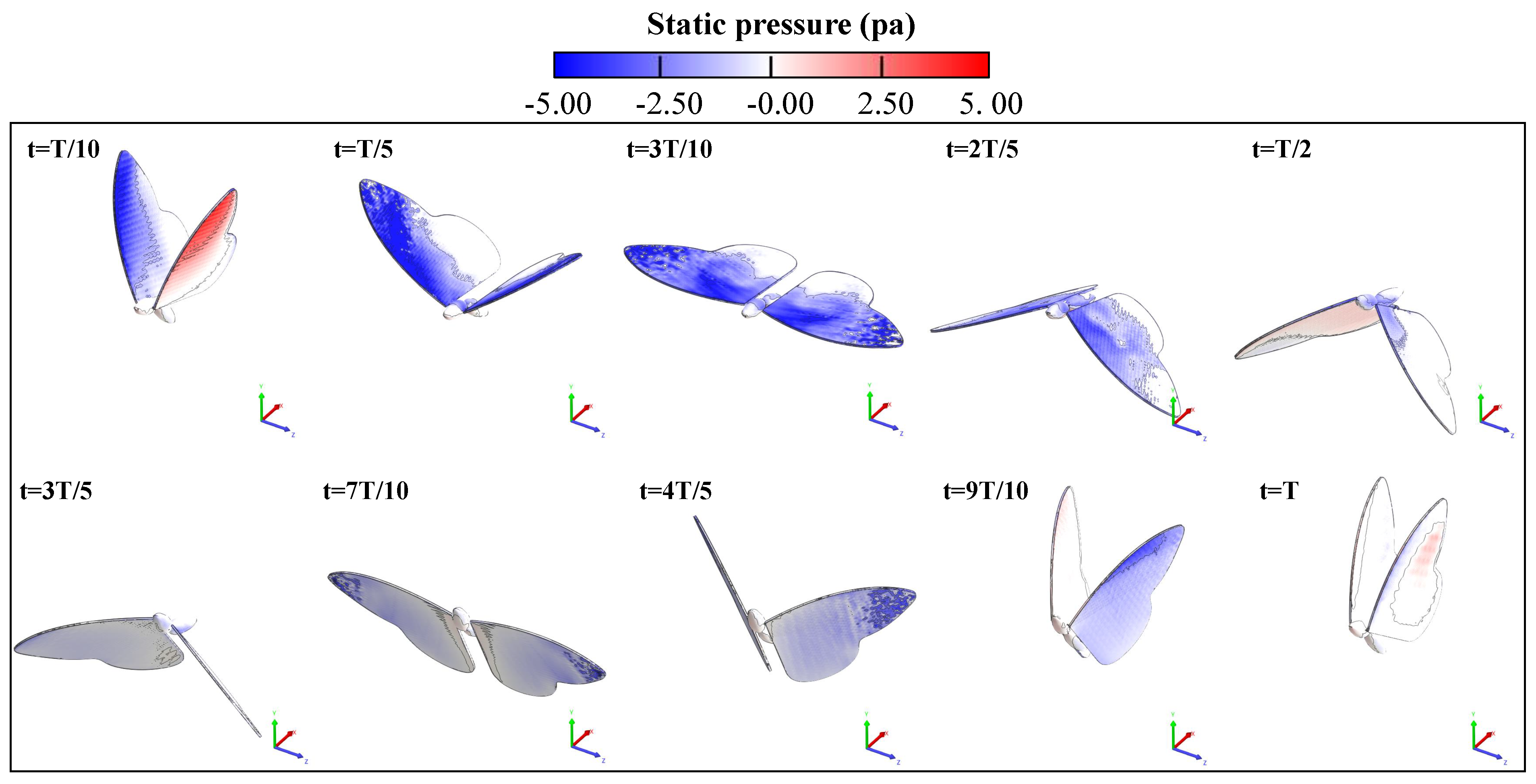
3.3.2. Surface Pressure Distribution

Figure 15 shows that the low-pressure regions appear on the dorsal side of the wing, whereas the high-pressure regions appear on the ventral side in the DS. Due to this pressure distribution, the lift force has a large positive value currently. This pressure distribution can be caused by the vortices (WTV and LEV) on the dorsal surface of the wing and the increase in the pressure of the air on the ventral side. The low-pressure region is attached near the leading edge on the dorsal surface of the wings and gradually comes off as it gets closer to the wing tip. It is likely to be created by the LEV. The low-pressure region appears near the wing tip on the dorsal surface of the wing. It seems to be induced by the WTV. On the other hand, the high-pressure region appears on the ventral side of the wing for all cross sections because the downward velocity of the wings is the maximum around this time, and it is likely to be larger than the downward velocity of the ambient air. Therefore, the air in the ventral side is pressed by the wings, and, consequently, the pressure increases in this region. The pressure difference between the upper and lower surfaces of the hind wing relative to the front wing during the entire flight is small, so the contribution of the hind wing to lift and thrust is limited. During the entire flapping process, the pressure difference of the hind wings is always small due to the lower motion velocity of the hind wings relative to the air and the less influence of the leading-edge vortex. Therefore, the fore wings contribute mainly to the generation of lift and thrust, and the hind wings may play a positive role in flight stability.

4. Discussion

To reveal the unsteady aerodynamics of the butterfly in free flight, kinematic parameters under different flight conditions were obtained through biological observations, and corresponding kinematic curves were fitted. Based on these, the influence of butterfly kinematics parameters on flight performance was studied. The simulation analysis clarifies that the pitching motion of the body is extremely necessary for butterfly flight, and the balanced position of the pitching motion needs to be an appropriate value, which is about 34°. The effect of flight velocity on aerodynamic forces is relatively linear within the test velocity range. The average lift and drag generated by flapping wing increase synchronously with flight velocity, and the peak values of the instantaneous aerodynamic forces increase accordingly. Besides, as it increases, the lift always increases, but the drag decreases first and then increases. It is necessary to choose an appropriate kinematic parameter to ensure that the lift and thrust are sufficient for flight.
The amplitude of the flapping angle is not as large as possible. The simulation of this research indicates that the butterfly has a large average lift (close to the butterfly’s own gravity) and produces a certain thrust when it is 60°, which is consistent with the observation results. The butterfly needs to adjust the related parameters in real-time in cooperation with the body pitch movement according to different lift requirements for achieving the best kinematic performance.
A detailed computational fluid dynamics simulation analysis was performed by the Lattice Boltzmann method to obtain the kinematic parameters which influence the generation and change of lift and thrust. The optimal kinematic parameters of the butterfly under the determined flight velocity were found. Visualization of 3D vortex structures of the flow field around the model was applied, and 3D structures of LEV, WTV, and TEV were analyzed in this study. The formation and development of the vortices were observed further to explain the high-lift mechanism during the free forward flight. A pair of conical leading-edge vortices is attached to the leading edges of the left and right wings throughout the downstroke. Pressure distribution on butterfly wings and body surface reveal unsteady aerodynamics. The simulation results of the instantaneous aerodynamic curve can confirm the generation mechanism of the corresponding aerodynamic force.
Although the experimental cases are not rich enough, the qualitative analysis of the kinematic parameters of the butterfly forward flight is obtained, and the variation trend of the kinematic parameters affecting the flight mechanism is clarified. More experiments and simulation work of butterfly free flight will be carried out in the future.

5. Conclusions

Observations by the high-speed camera system show that the kinematics of the butterfly is particularly different from other small insects or very small insects: the AR of the butterflies is lower (even less than 2), the flapping frequency is lower (about 10 Hz), and the wings are not flipped during flapping. The butterfly’s body moves up and down with the obvious pitch motion. The high coupling of the body and the wing motion is the key to the lift generation and attitude adjustment during forward flight. Although the body pitch caused by unpredictable disturbances in the air can be compensated by the complex motions of wings such as forward sweep, backward sweep, and torsion, the stability of the longitudinal flight of the butterfly is still reduced when the abdomen is fixed relative to the thorax. Besides, the butterfly glides forward at a smaller open angle with wings close on its back before the DS. Although the glide time is short, it is considered a clever flight strategy to reduce energy consumption.
Through the co-simulation of ADAMS and XFlow, the numerical simulation calculation of the aerodynamic force of the butterfly in the vertical and horizontal directions is realized. Based on the simulation analysis of four key kinematic parameters, the influence of each kinematic parameter on the flying performance of butterflies was obtained. Furthermore, an optimized multi-rigid body flight kinematics model of the butterfly was established. Simultaneously, Lattice Boltzmann method was used to show the vortices structure generated by the butterfly during forward flight. By analyzing the formation and development of vortices, the characteristics of butterfly flight were revealed.
In the future, a flapping wing air vehicle inspired by the flight mechanism of the butterfly will be designed and developed to refer to the similar kinematics equation in this study so that the controllable longitudinal stability of the robot will be achieved.

Author Contributions

Y.Z. and S.W. conceived this paper. Y.Z. and X.W. planned the experiments. Y.Z., W.H. and Q.W. conducted the experiments and simulations. The results were analyzed by all authors. The manuscript was written by Y.Z. and reviewed by all authors. All authors have read and agreed to the published version of the manuscript.

Funding

This research was funded by the National Natural Science Foundation of China (Nos. 51675019, 51620105010, and 51575019) and National Science and Technology Major Project (Nos. 2017-V-0010-0060 and 2017-V-0010-0062).

Informed Consent Statement

Not applicable.

Acknowledgments

The authors thank Longfei Zhao for his help with the numerical method proposed and simulations conducted.

Conflicts of Interest

The authors declare no conflict of interest.

Abbreviations

The following abbreviations are used in this manuscript:
CFDComputational fluid dynamics
FWForewing
HWHindwing
COGCenter of gravity
COMCenter of mass
DOFDegree of freedom
ARAspect ratio
LBMLattice Boltzmann method
DSDownstroke
USUpstroke
LEVLeading-edge vortex
WTVWing-tip vortex
TEVTrailing edge vortex
SFVSecondary flow vortex

References

  1. Brodsky, A.K. The Evolution of Insect Flight; Oxford University Press: Oxford, UK, 1994. [Google Scholar]
  2. Mao, S. Aerodynamics of insect flight. Adv. Mech. 2015, 45, 1–28. [Google Scholar]
  3. Wootton, R.J. Functional morphology of insect wings. Annu. Rev. Entomol. 1992, 37, 113–140. [Google Scholar] [CrossRef]
  4. Tanaka, H.; Shimoyama, I. Forward flight of swallowtail butterfly with simple flapping motion. Bioinspir. Biomim. 2010, 5, 026003. [Google Scholar] [CrossRef]
  5. Wootton, R.; Herbert, R.; Young, P.; Evans, K. Approaches to the structural modelling of insect wings. Philos. Trans. R. Soc. Lond. Ser. B Biol. Sci. 2003, 358, 1577–1587. [Google Scholar] [CrossRef] [Green Version]
  6. Bode-Oke, A.T.; Zeyghami, S.; Dong, H. Optimized Body Deformation in Dragonfly Maneuvers. arXiv 2017, arXiv:1707.07704. [Google Scholar]
  7. Ellington, C. The aerodynamics of hovering insect flight. III. Kinematics. Philos. Trans. R. Soc. Lond. Ser. B Biol. Sci. 1984, 305, 41–78. [Google Scholar]
  8. Dickinson, M.H.; Götz, K.G. The wake dynamics and flight forces of the fruit fly Drosophila melanogaster. J. Exp. Biol. 1996, 199, 2085–2104. [Google Scholar]
  9. Dickinson, M.H.; Lehmann, F.O.; Sane, S.P. Wing rotation and the aerodynamic basis of insect flight. Science 1999, 284, 1954–1960. [Google Scholar] [CrossRef]
  10. Dudley, R.; Srygley, R. Flight physiology of neotropical butterflies: allometry of airspeeds during natural free flight. J. Exp. Biol. 1994, 191, 125–139. [Google Scholar]
  11. Willmott, A.P.; Ellington, C.P. The mechanics of flight in the hawkmoth Manduca sexta. I. Kinematics of hovering and forward flight. J. Exp. Biol. 1997, 200, 2705–2722. [Google Scholar]
  12. Ellington, C.P. The aerodynamics of hovering insect flight. I. The quasi-steady analysis. Philos. Trans. R. Soc. Lond. Ser. B Biol. Sci. 1984, 305, 1–15. [Google Scholar]
  13. Ellington, C.P. The aerodynamics of hovering insect flight. II. Morphological parameters. Philos. Trans. R. Soc. Lond. Ser. B Biol. Sci. 1984, 305, 17–40. [Google Scholar]
  14. Ellington, C.P. The aerodynamics of hovering insect flight. VI. Lift and power requirements. Philos. Trans. R. Soc. Lond. Ser. B Biol. Sci. 1984, 305, 145–181. [Google Scholar]
  15. Cheng, X.; Sun, M. Wing-kinematics measurement and aerodynamics in a small insect in hovering flight. Sci. Rep. 2016, 6, 1–12. [Google Scholar] [CrossRef] [Green Version]
  16. Dao, T.T.; Loan Au, T.K.; Park, S.H.; Park, H.C. Effect of Wing Corrugation on the Aerodynamic Efficiency of Two-Dimensional Flapping Wings. Appl. Sci. 2020, 10, 7375. [Google Scholar] [CrossRef]
  17. Sane, S.P.; Dickinson, M.H. The aerodynamic effects of wing rotation and a revised quasi-steady model of flapping flight. J. Exp. Biol. 2002, 205, 1087–1096. [Google Scholar]
  18. Ellington, C. Unsteady aerodynamics of insect flight. Symp. Soc. Exp. Biol. 1995, 49, 109–129. [Google Scholar]
  19. Miller, L.A.; Peskin, C.S. Flexible clap and fling in tiny insect flight. J. Exp. Biol. 2009, 212, 3076–3090. [Google Scholar] [CrossRef] [Green Version]
  20. Sunada, S.; Kawachi, K.; Watanabe, I.; Azuma, A. Performance of a butterfly in take-off flight. J. Exp. Biol. 1993, 183, 249–277. [Google Scholar]
  21. Imura, T.; Fuchiwaki, M.; Tanaka, K. Dynamic Behaviors of Butterfly Wing and Their Application to Micro Flight Robot. In Proceedings of the Fluids Engineering Division Summer Meeting, Vail, CO, USA, 2–6 August 2009; Volume 43727, pp. 1687–1694. [Google Scholar]
  22. Jayakumar, J.; Senda, K.; Yokoyama, N. Control of Pitch Attitude by Abdomen during Forward Flight of Two-Dimensional Butterfly. J. Aircr. 2018, 55, 2327–2337. [Google Scholar] [CrossRef]
  23. Senda, K.; Obara, T.; Kitamura, M.; Nishikata, T.; Hirai, N.; Iima, M.; Yokoyama, N. Modeling and emergence of flapping flight of butterfly based on experimental measurements. Robot. Auton. Syst. 2012, 60, 670–678. [Google Scholar] [CrossRef] [Green Version]
  24. Srygley, R.; Thomas, A. Unconventional lift-generating mechanisms in free-flying butterflies. Nature 2002, 420, 660–664. [Google Scholar] [CrossRef]
  25. Okamoto, M.; Sunada, S.; Tokutake, H. Stability analysis of gliding flight of a swallowtail butterfly Papilio xuthus. J. Theor. Biol. 2009, 257, 191–202. [Google Scholar] [CrossRef]
  26. Bomphrey, R.J.; Taylor, G.K.; Thomas, A.L. Smoke visualization of free-flying bumblebees indicates independent leading-edge vortices on each wing pair. Exp. Fluids 2009, 46, 191–202. [Google Scholar] [CrossRef]
  27. Ke, X.; Zhang, W. Wing geometry and kinematic parameters optimization of flapping wing hovering flight. Appl. Sci. 2016, 6, 390. [Google Scholar] [CrossRef] [Green Version]
  28. Sridhar, M.; Kang, C.K.; Landrum, D.B. Beneficial Effect of the Coupled Wing-Body Dynamics on Power Consumption in Butterflies. In Proceedings of the AIAA Scitech 2019 Forum, San Diego, CA, USA, 7–11 January 2019; p. 0566. [Google Scholar]
  29. Senda, K.; Sawamoto, M.; Shibahara, T.; Tanaka, T. Study on flapping-of-wings flight of butterfly with experimental measurement. In Proceedings of the AIAA Atmospheric Flight Mechanics Conference and Exhibit, Providence, RI, USA, 16–19 August 2004; p. 5368. [Google Scholar]
  30. Sridhar, M.; Kang, C.K.; Landrum, D.B. Instantaneous lift and motion characteristics of butterflies in free flight. In Proceedings of the 46th AIAA Fluid Dynamics Conference, Washington, DC, USA, 13–17 June 2016; p. 3252. [Google Scholar]
  31. Tang, H.; Lei, Y.; Li, X.; Fu, Y. Numerical Investigation of the Aerodynamic Characteristics and Attitude Stability of a Bio-Inspired Corrugated Airfoil for MAV or UAV Applications. Energies 2019, 12, 4021. [Google Scholar] [CrossRef] [Green Version]
  32. Triantafyllou, M.S.; Triantafyllou, G.S. An efficient swimming machine. Sci. Am. 1995, 272, 64–70. [Google Scholar] [CrossRef]
  33. Suzuki, K.; Minami, K.; Inamuro, T. Lift and thrust generation by a butterfly-like flapping wing–body model: Immersed boundary–lattice Boltzmann simulations. J. Fluid Mech. 2015, 767, 659–695. [Google Scholar] [CrossRef] [Green Version]
  34. Holman, D.M.; Brionnaud, R.; Martinez, F.; De Mier, M. Advanced aerodynamic analysis of the NASA high-lift trap wing with a moving flap configuration. In Proceedings of the 30th AIAA Applied Aerodynamics Conference, New Orleans, LA, USA, 25–28 June 2012; p. 2923. [Google Scholar]
  35. Povitsky, A. Modeling of Pitching and Plunging Airfoils in Proximity for Thrust Generation. In Proceedings of the 46th AIAA Fluid Dynamics Conference, Washington, DC, USA, 13–17 June 2016; p. 4340. [Google Scholar]
  36. Jiao, Z.; Zhao, L.; Shang, Y.; Sun, X. Generic analytical thrust-force model for flapping wings. AIAA J. 2018, 56, 581–593. [Google Scholar] [CrossRef]
  37. Liu, H.; Kawachi, K. A numerical study of insect flight. J. Comput. Phys. 1998, 146, 124–156. [Google Scholar] [CrossRef]
  38. Fuchiwaki, M.; Kuroki, T.; Tanaka, K.; Tababa, T. Dynamic behavior of the vortex ring formed on a butterfly wing. Exp. Fluids 2013, 54, 1–12. [Google Scholar] [CrossRef] [Green Version]
  39. Yokoyama, N.; Senda, K.; Iima, M.; Hirai, N. Aerodynamic forces and vortical structures in flapping butterfly’s forward flight. Phys. Fluids 2013, 25, 021902. [Google Scholar] [CrossRef] [Green Version]
  40. Fei, Y.H.J.; Yang, J.T. Importance of body rotation during the flight of a butterfly. Phys. Rev. E 2016, 93, 033124. [Google Scholar] [CrossRef] [PubMed]
  41. Wan, H.; Dong, H.; Gai, K. Computational investigation of cicada aerodynamics in forward flight. J. R. Soc. Interface 2015, 12, 20141116. [Google Scholar] [CrossRef] [Green Version]
Figure 1. Observation experiment for butterfly flight based on high-speed camera: (a) geometry of a Chilasa clytia and the computational model with mesh, butterfly body mesh model; (b) live butterfly with the forewing (FW) and hindwing (HW) in natural environment; (c) schematic diagram of butterfly observation feature points and body kinematic parameters; (d) experiment system; and (e) three coordinate systems to describe the motion of a butterfly, namely the inertial coordinate system ( X , Y , Z ) , the body-fixed coordinate system ( X b , Y b , Z b ) and wing-fixed coordinate system ( X w , Y w , Z w ) .
Applsci 11 02620 g001
Figure 2. Computational fluid simulation set-up and resolution-independent study: (a) fluid computational domain for flight simulation of the butterfly multi-body model; (b) domain structure with lattice mesh on the middle symmetry plane of the butterfly; (c) the aerodynamic forces of the butterfly under three-resolution set-ups ( F x , horizontal force; F y , vertical force); and (d) the average aerodynamic forces under three-resolution set-ups.
Applsci 11 02620 g002
Figure 3. The real motion (top) and prescribed motion (bottom) of the butterfly during a stroke: (a,e) start of downstroke; (b,f) mid-downstroke; (c,g) start of upstroke; and (d,h) mid-upstroke.
Applsci 11 02620 g003
Figure 4. Snapshots from the front-view camera of a butterfly in forward flight: VC1 (a); and VC2 (b). Trajectories of the butterfly feature points in the upward direction (along the Y-axis) and the forward direction (along the X-axis) during forward flight: VC1 (c); and VC2 (d).
Applsci 11 02620 g004
Figure 5. Time variations of body kinematics of VC1: (a) displacement of the joint point during forward flight; (b) velocity of the butterfly centroid (joint point); (c) acceleration of the butterfly centroid and FFT smoothing for the second flapping cycle; and (d) oscillation of thoracic pitch angle ( θ p ) and abdominal swing angle ( θ a ) . Grey shading indicates the DS, purple shading denotes the gliding moment, and white shading denotes the US.
Applsci 11 02620 g005
Figure 6. Time variations of body kinematics of VC2: (a) displacement of the joint point during forward flight; (b) velocity of the butterfly centroid (joint point); (c) acceleration of the butterfly centroid and FFT smoothing for the second flapping cycle; and (d) oscillation of thoracic pitch angle ( θ p ) and abdominal swing angle ( θ a ) . Grey shading indicates the DS, purple shading denotes the gliding moment, and white shading denotes the US.
Applsci 11 02620 g006
Figure 7. Time variations of wing tip kinematics of: VC1 (a); and VC2 (b).
Applsci 11 02620 g007
Figure 8. (a) The instantaneous aerodynamic forces of the butterfly accompanied by the change of B 0 in four flapping cycles; and (b) the average aerodynamic forces at different fixed pitch angles.
Applsci 11 02620 g008
Figure 9. (a) The instantaneous aerodynamic forces of the butterfly accompanied by the change of V in four flapping cycles; and (b) the average aerodynamic forces at different incoming flow velocity.
Applsci 11 02620 g009
Figure 10. (a) The instantaneous aerodynamic forces of the butterfly accompanied by the change of γ in four flapping cycles; and (b) the average aerodynamic forces at different phase differences.
Applsci 11 02620 g010
Figure 11. (a) The instantaneous aerodynamic forces of the butterfly accompanied by the change of A f in four flapping cycles; and (b) the average aerodynamic forces at different amplitude of flapping angles.
Applsci 11 02620 g011
Figure 12. 3D vortex structures in the flow for the butterfly in one flapping cycle at t ^ = 0.1, 0.2, 0.3, 0.4,0.5, 0.6, 0.7, 0.8, 0.9, and 1.0 The iso-surface of the vorticity ( ω = 7 × 10 2 s 1 ).
Applsci 11 02620 g012
Figure 13. Vortical structures visualized by the vorticity. The iso-surface of ω = 6 × 10 2 s 1 is drawn: (a) top view; and (b) side view at t ^ = 3.5.
Applsci 11 02620 g013
Figure 14. High-resolution visualization of 3D vortex structures in forward flight. The iso-surface of the vorticity ( ω = 7 × 10 2 s 1 ) at t ^ = 0.25 (a), 0.5 (b), 0.75 (c), and 1 (d), respectively.
Applsci 11 02620 g014
Figure 15. Surface pressure distribution of one butterfly flapping cycle. The top row represents snapshots during the DS at t ^ = 0.1, 0.2, 0.3, 0.4, and 0.5, respectively. The bottom row represents snapshots during the DS at t ^ = 0.6, 0.7, 0.8, 0.9, and 1.0, respectively.
Applsci 11 02620 g015
Table 1. Morphological parameters of the butterfly (Chilasa clytia).
ParametersValue
m (kg)3.5 × 10 4
m t (kg)1.02 × 10 4
m a (kg)1.12 × 10 4
L t (m)9.1 × 10 3
w t (m)4.4 × 10 3
L a (m)1.3 × 10 2
w a (m)4.3 × 10 3
m w (kg)5.2 × 10 5
L t i p (m)8.29 × 10 2
2 S w (m 2 )2.57 × 10 3
m g / ( 2 S w ) (N/m 2 )1.36
c (m)3.55 × 10 2
Table 2. Parameters defining the simulation model of the butterfly.
ParametersDescriptionValue
S (m)Wingspan8.5 × 10 2
Δ l (m)Wing-root offset1.5 × 10 3
c (m)Chord length3.6 × 10 2
L t (m)Thoracic length1.0 × 10 2
L a (m)Abdominal length1.5 × 10 2
h w (m)Wing thickness2.0 × 10 4
Table 3. Resolutions set-ups for the resolution-dependency study.
Parameterss (Coarse)s/2 (Medium)s/4 (Fine)
Near wall (m)1.25 × 10 3 6.25 × 10 4 3.125 × 10 4
Far field (m)1.0 × 10 2 5.0 × 10 3 2.5 × 10 3
Elements at t = 0.1 s223,8621,475,11110,915,276
Table 4. Kinematics parameters of the butterfly obtained by experimental observation.
ID θ 1 p max θ 1 p min θ ¯ 1 p θ 1 a max θ 1 a min θ ¯ 1 a θ 2 p max θ 2 p min θ ¯ 2 p θ 2 a max θ 2 a min θ ¯ 2 a t total A ¯ f f ¯
VC162.719.238.5−11.9−72.8−33.779.315.242.2−17.8−89.4−47.729012010.6
VC259.1−0.129.213.3−46.9−13.889.723.560.8−17.3−88.6−42.22971359.9
Table 5. Kinematic parameters K set-ups of four cases.
ParametersCase 1Case 2Case 3Case 4
f (Hz)10101010
A f (deg.)606060variable
A p (deg.)0303030
A 0 (deg.)20202020
B 0 (deg.)variable343434
C 0 (deg.)−35−35−35−35
γ (rad) π / 2 π / 2 variable π / 2
V (m/s)1variable11
Publisher’s Note: MDPI stays neutral with regard to jurisdictional claims in published maps and institutional affiliations.

