1. Introduction
Agriculture and forestry applications are associated with different tasks, where it is necessary to deploy a significant amount of physical effort to carry them out. Very often, these tasks are performed under adverse climatic conditions [
1]. In order to diminish the associated effort to agricultural and forestry work, a variety of farm machinery has been developed, such as the tractor, with some advantages, but also increasing the number of fatal accidents [
2].
One of the higher causes of deceases in the farming sector is the overturn of tractors not equipped with a rollover protection system (ROPS) [
3]. However, a ROPS alone or combined with additional mechanic energy absorbers, may dissipate a large amount of rollover energy [
4]. As a consequence, the combination of this type of protection systems, in combination with the use of a safety belt can increase, significantly, the safety of an agricultural, forestry, or industrial vehicle, in the event of overturn [
5].
There is a large number of tractors without an appropriate structure to protect the operator in case of rollover in different countries of the European Union [
6]. In the USA, farm tractor overturn is the main cause of death in agriculture: 1412 operators died, from 1992 to 2005, due to this cause [
7].
This fact can be extrapolated to the sector of quad bikes (QBs), where a majority of them lack an installed ROPS. All-terrain vehicles (ATVs) are considered as unstable vehicles, due to their low distance between axles and tread, as well as their high center of gravity (CG), which increases the probability of overturn accidents in steep, rough or irregular ground that are common in farms [
8,
9]. In the year 2010 in Australia, around 80% of the 270,000 ATVs categorized as QBs were sold for the farming sector, which is significantly different to the distribution of ATVs in the USA [
10].
The rollover tendency of an ATV is determined by its stability, both static and dynamic, as well as its operating conditions. Stability in side or longitudinal overturning is conditioned by three parameters: tread (distance between the center of the wheels), distance between axles and height of the CG, specifically the quotient between the height of the CG and half the tread, as well as the distance between axles [
11]. This fact means that the larger the tread and the distance between axles, and the smaller the height of the CG, the vehicle is more statically stable against overturn. The stability of an ATV is influenced by their operating conditions, such as speed, turning radius, slope, as well as the condition of the ground [
12].
Reference [
13] described a vehicle accelerator allowing the acceleration of the ATV in a given direction and orientation, able to provide enough kinetic energy to initiate side or inverse rollover. In this device, the ATV lays on a sled, which is placed on a sloping ramp, where the controlled variables are the sled sliding distance and the tilt angle.
Delta-V experts in Australia [
14] reported the results of a computer simulation study from 2013. The authors created a model of an ATV to simulate forces in parts of the body of the driver, using the commercial software, PC-Crash. They validated the rollover tests of the ATV model with data from a study of Snook for two different safety configurations of the ATV: with and without a crush protection device (CPD). Rollover simulations with drivers without restrictions were compared to four real cases (100 simulations for each case and configuration), in order to assess the injuries caused by the impact and crushing of the driver of the ATV.
Based on simulations of an ATV without protection and an ATV equipped with a quad bar, the authors concluded that the driver could suffocate mechanically 32 and 17 times, respectively; hence, the quad bar reduced the risk by 57%. The authors deduced that, due to ATV overturn, a risk of grave and fatal injuries existed, and that the installation of a CPD should be considered to mitigate the possibility that the driver could get trapped or crushed, as a result of vehicle rollover. Moreover, the authors concluded that in the case that the ATV was equipped with a CPD, the driver could have saved his life in the event of vehicle overturn.
Reference [
15] developed a research project with the purpose of improving ATV safety. The original objective was testing ATVs alone, however, later on, the scope of the project was increased to include tests of side by side vehicles (SSVs). In that project, tests focused on side, forward, and backward vehicle rollover.
There are not many reports about the development of rollover tests for vehicles of the type ATV-Quad. One relevant study was developed by [
16]. Its main objective was to improve the safety of QBs by the critic assessment, research and the development of tests, in order to identify the engineering and design characteristics, required to improve the static stability, dynamic response, and rollover resistance, including protection devices for the operator.
The planning of rollover resistance tests included 65 QB tests, SSV tests, as well as inspections of SSVs focused in four different areas, related to the rollover resistance features of a vehicle, such as the measurement of contact loads to the ground, inspections of occupants’ retention in the SSV, dynamic rollover tests, and tests of structural loads on rollover protection systems (ROPS) installed in SSVs.
This research work presents the design, manufacturing, and validation process for the design of the structure, electronics, and control of an ATV rollover test bench. In order to achieve this objective, several rollover test benches, described in the literature, have been analyzed. The new bench, which has been developed and reported in this manuscript, significantly improves the functionality of the bench for performing rollover tests on it. Moreover, the validation process has allowed one to prove its functionality and ability to perform a wide range of rollover tests with different models of QBs.
The main contributions of the presented rollover are the versatility of possible rollover tests (frontal, rear and lateral rollover) that can be carried out, the possibility of varying the turning speed of the platform, the possibility of conducting non-destructive rollover tests, as well as the “real-time” acquisition of data (rollover angle, rollover instant) have been highlighted. In addition, through this test bench the pathologies of the dummy can be studied after impact due to rollover.
The present paper is organized as follows:
Section 2 describes the design process developed to manufacture a novel ATV rollover test bench, including the design of the mechanical structure, implementation of the instrumentation, electronics and control. The validation of the bench operation and the results of the tests have been addressed in
Section 3, while the following section discusses the results. Conclusions are presented in
Section 4.
2. Materials and Methods
2.1. Design Requirement
The aim of the present research project is to develop a rollover test bench for vehicles of the type ATV-Quad. In order to achieve this objective, the stages of the design, manufacturing and validation of a test project were carried out. It presented the following main characteristics:
The development of the rollover tests reported in this manuscript was carried out using this newly conceived test bench, which was designed and developed specifically for the mentioned research rising of the wheels in the rollover test.
The tilting speed of the structure is at least 1°/s.
The data acquisition is performed at a minimal sampling rate of 100 Hz.
The video recording system is placed at 45°, referred to the front view.
The inclinable structure presents a single plane and adjustable tilt angle, in a range from 0° to 80°, measured with respect to a horizontal ground reference.
It presents a flat and rigid surface and large enough to contain the four wheels of the tested ATV.
The electronic system for the measurement of the tilt angle presents a measurement range from 0° to 180° and a resolution of at least 0.1°.
The surface holds a load cell under every one of the wheels of the vehicle. Each cell presents a measurement range up to 700 kg and a resolution of at least 0.5 kg.
High friction surface in the upper part of the load cells, to prevent slippage of the wheel.
The vehicle is fastened to the bench by using belts, loose enough to allow a total decompression of the suspension and a minimal bench in the Public University of Navarre, were completed. This project was carried out, starting from the project reported by [
16] and following their main results.
The design of the test bench is composed by three differentiated stages: (i) structural design, (ii) electronic system design, and (iii) control algorithm design. The requirements of the structural design stage are the following:
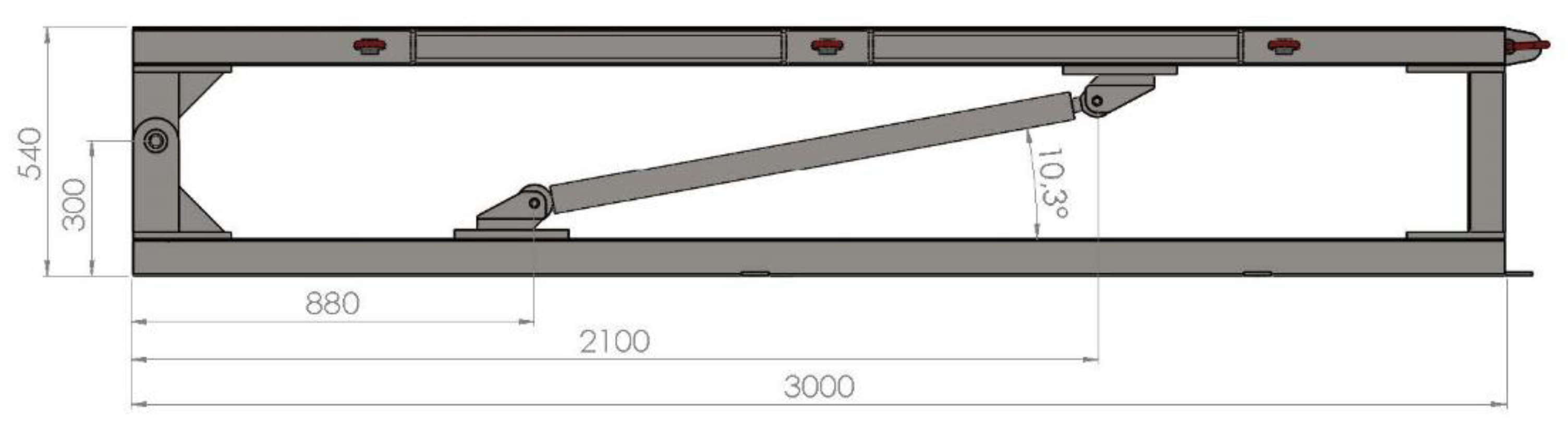
The test bench is composed by two squared platforms: a fixed one and a mobile one. Their dimensions are 3000 × 3000 mm2. The mobile platform is able to rotate with respect to the fixed one by means of a pair of hydraulic cylinders. They can simulate a vehicle rollover and a tilt angle of 75°, referred to the ground, can be reached.
It presents four mobile connections where the load cells have been installed, to allow the development of rollover tests at different directions. A function of the load cells is to determine the time, when the overturn of the vehicle is produced.
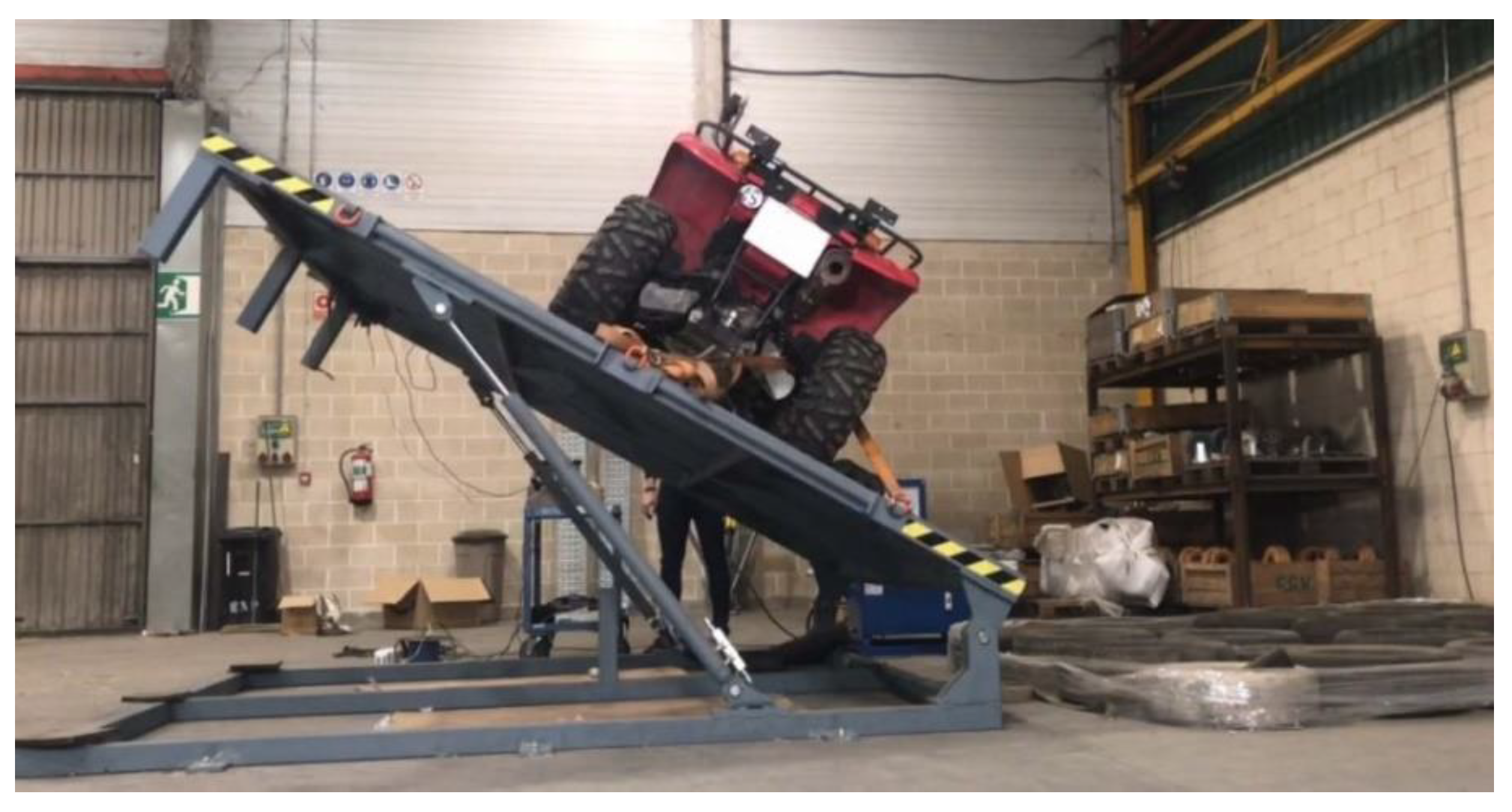
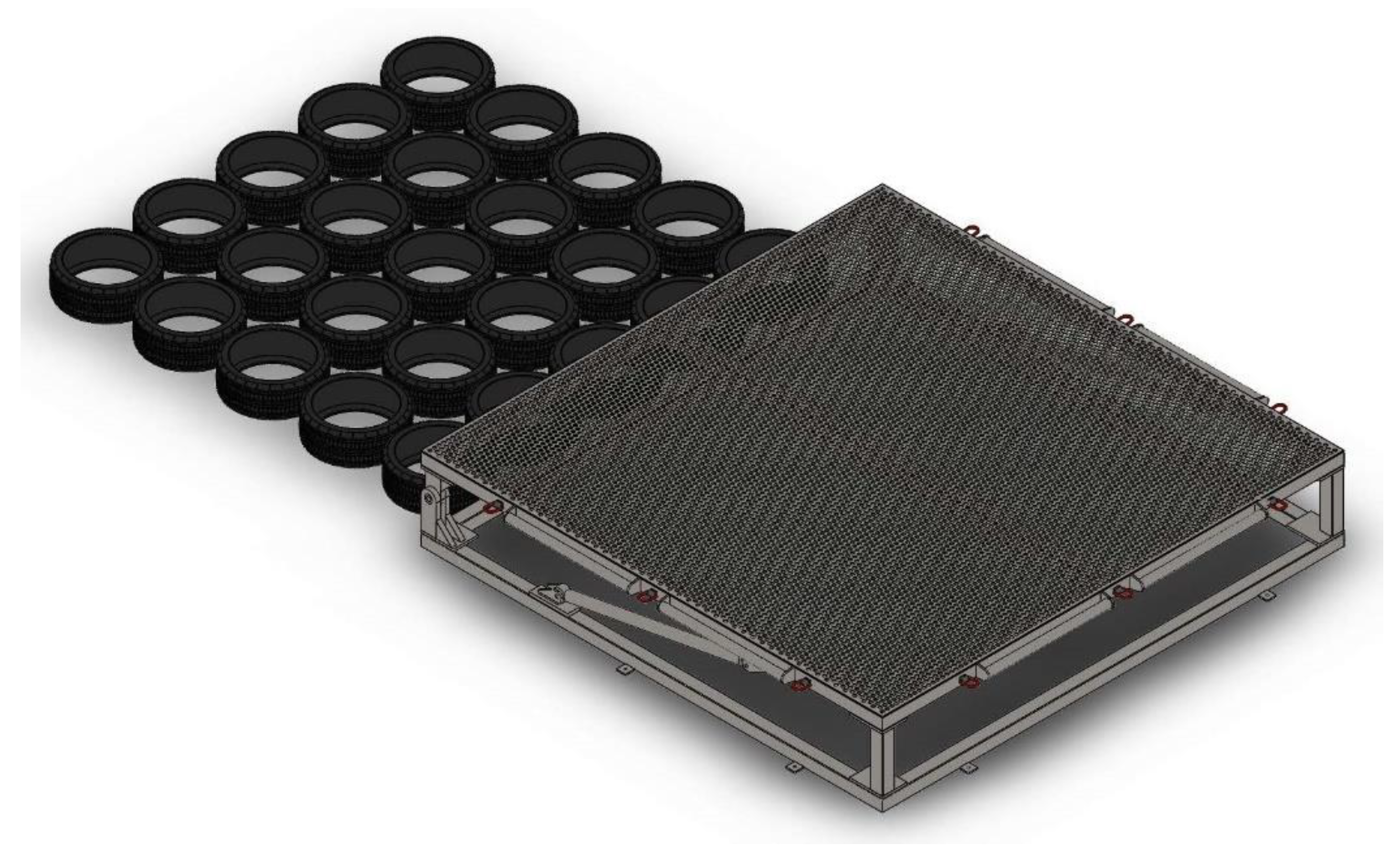
According to the rollover tests protocol, it is necessary to take into account that some of the tests are non-destructive ones; hence, some anchor points are installed in the sides of the bench in order to fix the vehicle, preventing its collision to the ground. Moreover, a bed of tires has been prepared, directly on the ground, in the impact area of the vehicle after the rollover test, for the non-destructive tests.
The angular velocity control of the test bench can be set up by means of a console panel. The preset values are 4°/s for a fast rotation, and 0.2°/s for a reduced angular velocity.
On the other hand, the requirements for the design stage of the electronic system are as follows:
The test bench counts in a subsystem to measure the tilt angle of the mobile platform. Thanks to this subsystem, it is possible to measure the rollover angle of the tested ATV-Quad. The measurement range of the system is 0°–90°, that is to say, from a horizontal position of the mobile platform to a perpendicular direction, referred to the ground. A display shows the tilt angle measurement, at every instant, which is also recorded.
Another subsystem determines the precise instant of time, where the rollover is produced, as well as the rollover angle. This instant is calculated by means of the measurements of the four load cells placed under the wheels of the ATV.
Finally, below are listed the requirements for the stage of the control algorithm design:
The control of the electronic system and the test bench is performed by an algorithm stored in a microprocessor. This system is in charge of processing all the signals of the different sensors, in order to obtain the value of the rollover tilt angle.
The rotation of the test bench is developed by means of a button console, able to configure different speeds for rising and descending the mobile platform. For safety reasons, the button console counts with a system of instant interruption of the rotation by means of an emergency stop.
2.2. Structure Design: Test Bench Components
The design of the components of the test bench was performed using the software SolidWorks
® version 2018 (SolidWorks Corp., Waltham, MA, USA).
Figure 1 and
Figure 2 show the structure of the test bench as a result of the design stage.
The fixed and mobile platforms, included in the test bench, was built up from steel square hollow structural section profiles. A pair of hinges allowed the relative rotation between the mobile and the fixed platforms. Additionally, another pair of hinges were installed in each hydraulic cylinder, in a way that the extension of the cylinders produced the rotation of the mobile platform.
A perforated sheet was placed on the mobile platform, in order to support the load cells and to reduce the weight of the device, which supports the ATV-Quad in the development of the rollover tests. Moreover, some rings were installed, following the safety and health standard defined in the directive 2006/42/CE, for fastening the vehicle in the non-destructive tests. Additionally, these rings can be used as a part of a fastening system, through the external perimeter, for placing ramps in the operation of rising the ATV-Quad onto the test bench.
Some steel platens were installed in the fixed platform and screwed to the ground in order to keep fixed the complete structure. All the connections were reinforced by means of steel stiffeners.
2.3. Finite Element Analysis Tests
Before building the test bench, some requisites were verified by means of finite element analysis (FEM) tests. In particular, it was verified that the platform meets the minimal requisites of resistance. It was proven that the structure and the hydraulic actuators were over-dimensioned.
The structure should withstand around 300 kg, including a standard ATV-Quad and a dummy of 100 kg. In fact, the structure is able to successfully resist a weight up to 600 kg.
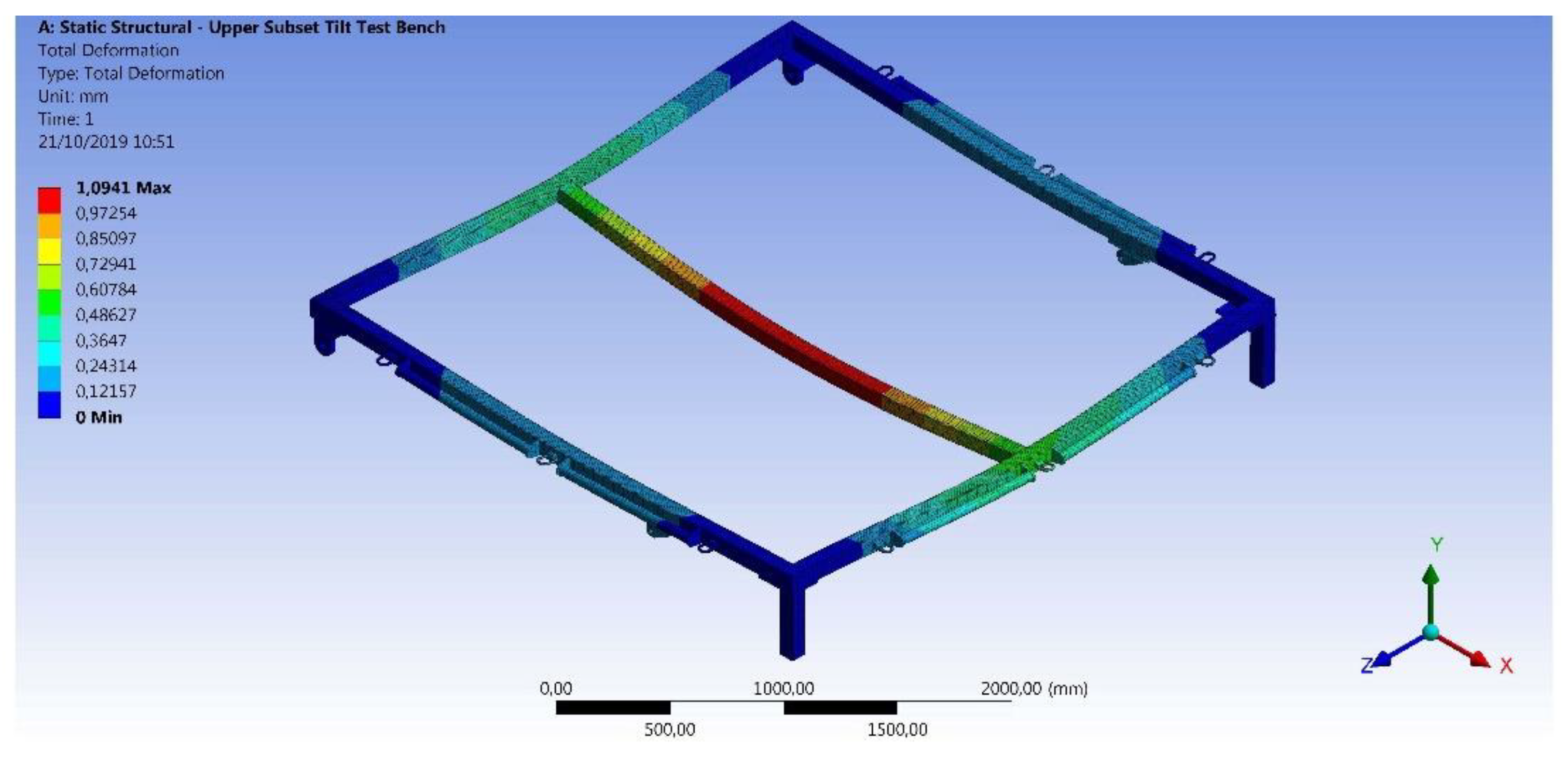
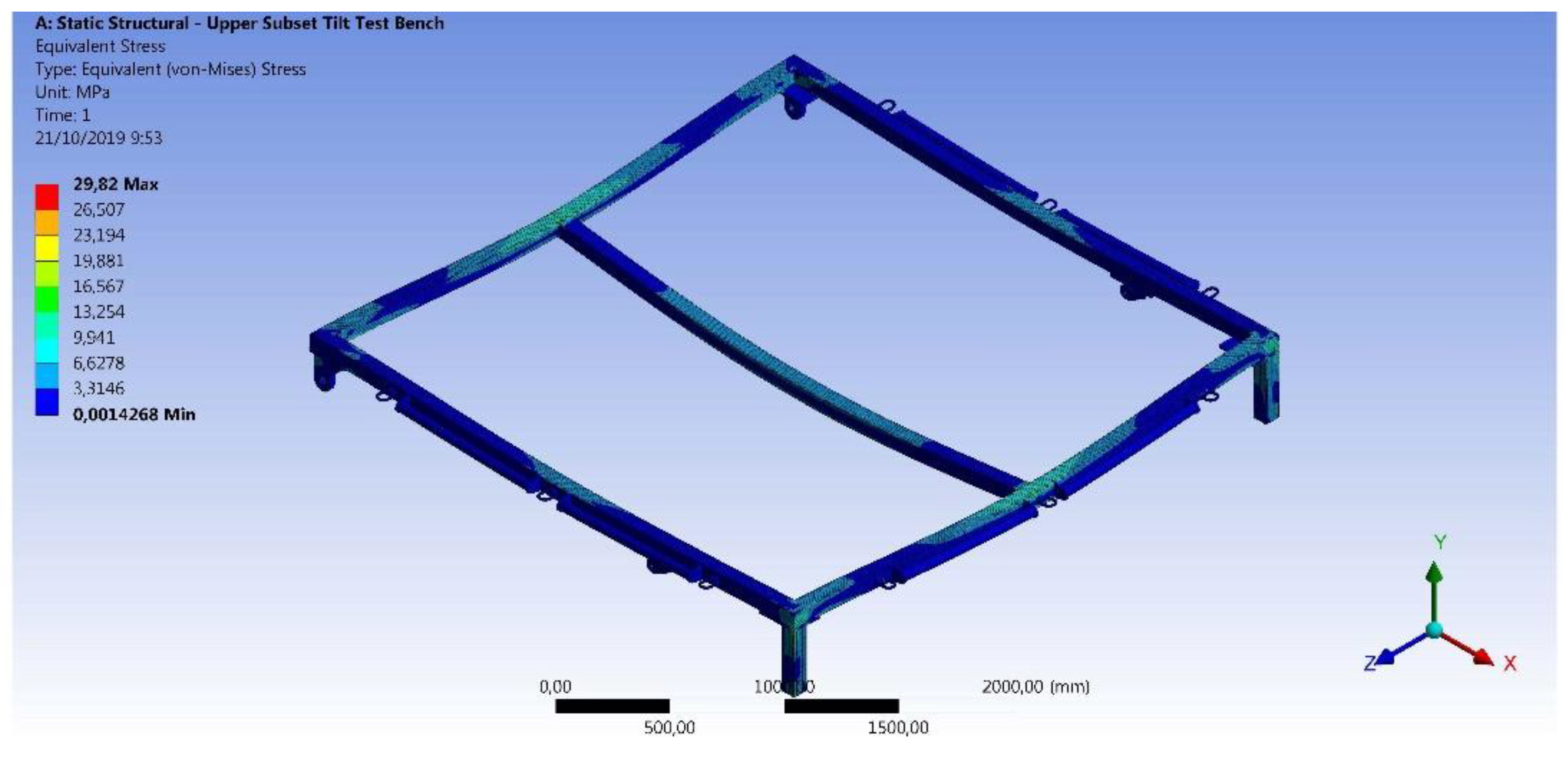
The verification of the resistance of the structure was performed by means of FEM analysis implemented in the software Marc Mentat ® v. 2016 (MSC Software Corp., Los Angeles, USA). In particular, the upper part of the test platform was analyzed, since it is the most critical part of the structure, as it directly supports both the ATV and the dummy. The FEM analysis was developed with standard steel as the material, with a density ρsteel = 7850 kg/m3 and a yield strength σy,steel = 275 MPa. The boundary conditions imposed fixed displacement in axis X, Y, and Z, in the inner surfaces of the holes of the hinges, around which the mobile platform rotates, as well as the lower surfaces of the mechanical elements that stand on the fixed surface. A distributed load of 2940 N was applied to all the profiles composing the mobile platform, since it corresponds to the static force applied by a quad, weighing 200 kg and a driver of 100 kg.
The obtained results showed that the maximal displacement took place in the inner square profile, with a value of
dmax = 1.0941 mm, as it can be seen in
Figure 3. On the other hand,
Figure 4 shows the maximal value of the equivalent von Mises stress, whose value is
σVM,max = 29.82 MPa. This value is reached in the inner corner of the mechanical element that stands on the fixed platform and is closer to the profile that withstand all the weight of the vehicle and its driver.
From the results that have been obtained in the FEM analysis, it can be stated that the test bench is appropriately designed for withstanding the weight and inertial forces that are originated during the vehicle rollover tests. This conclusion has been obtained from the fact that the yield strength of the steel, used as the building material of the bench, has not been reached at any position of the structure. In fact, the safety factor is:
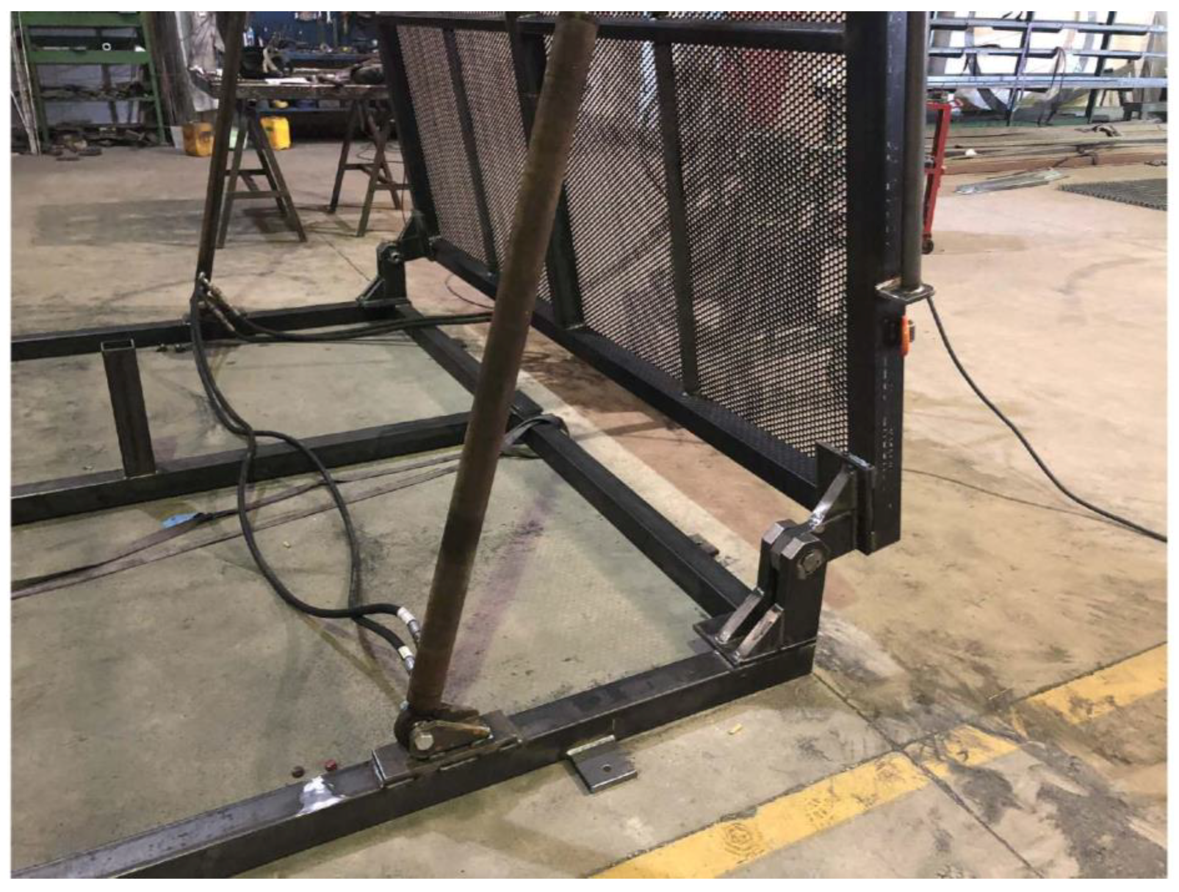
2.4. Structure Design: Hydraulic Pressure Group
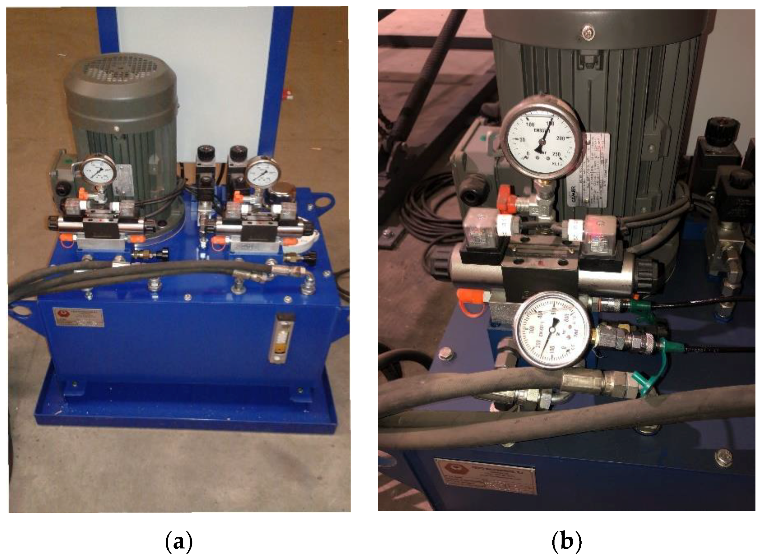
A hydraulic system pumps oil to the hydraulic cylinders of the bench. In contains two gear pumps, with a nominal working pressure of 140 bar, and a maximal pressure of 180 bar. This hydraulic system allows a variation in the rotation speed of the mobile platform of the testing bench. The hydraulic system has been depicted in
Figure 5a.
The hydraulic cylinders that have been installed, model DGN250, present a rod diameter of 30 mm, a piston diameter of 50 mm, and a stroke length of 1000 mm. They have been installed with an angle of 10.3°. These cylinders provide a net force of 27,480 N each, with a working pressure of 140 bar. The motion speed of the piston can be modified. The correct operation of the hydraulic system has been verified by a standard procedure. A picture of the hydraulic system checking is shown in
Figure 5b.
The thrust force (
Ft) and the traction pressure (
Pt) of each one of the hydraulic cylinders have been calculated as follows:
Both hydraulic cylinders produce a thrust force of 2.75 × 2 = 5.5
tn, which is enough to support the loads of the own weight of the upper platform, ATV-Quad and dummy (estimated at around 250–350 kg). A study of moments has been carried out for the validation of hydraulic cylinders.
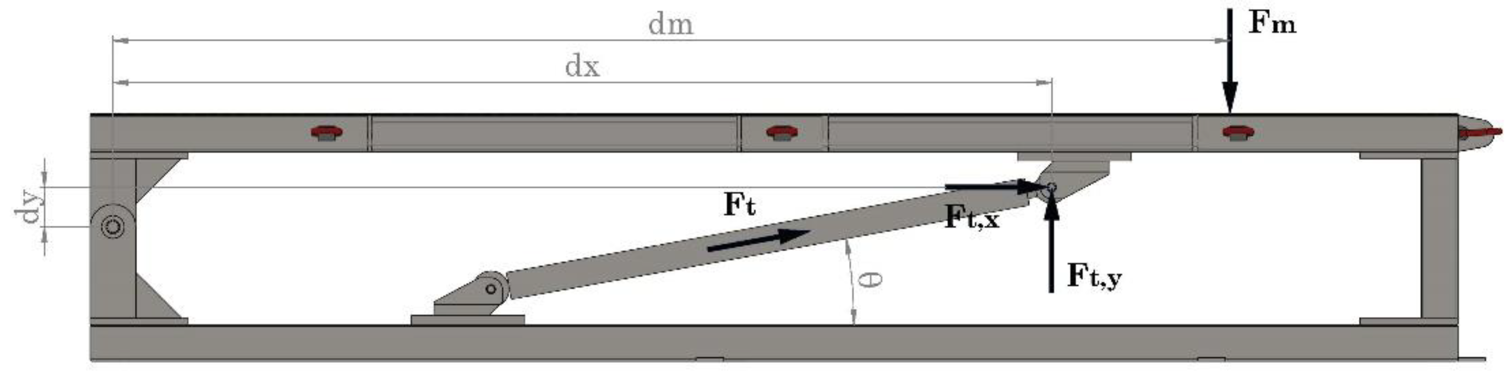
Figure 6 shows the acting forces and their point of application.
Notice that
Fm is the force applied by the ATV-Quad with the dummy mass,
Ft is the thrust force exerted by the hydraulic cylinder, and
Ft,x and
Ft,y and their horizontal and vertical components, respectively. The variables
dm,
dx and
dy are the distances from the point of application of the forces to the pivot point of the platform. All these parameters have been depicted in
Figure 6.
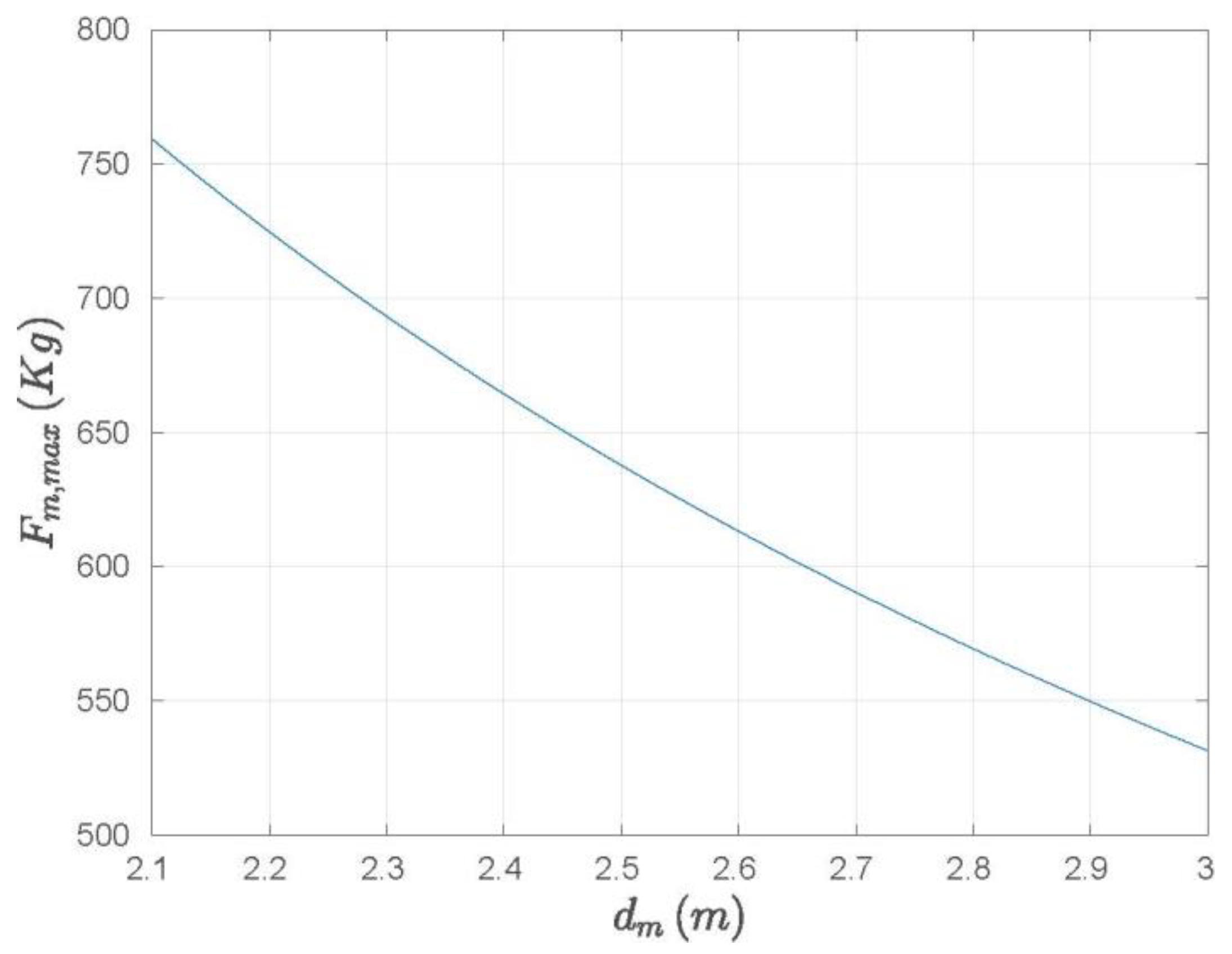
Performing the balance of moments at the pivot point, it has been obtained
Figure 7, where it can be observed that if the ATV-Quad (together with the dummy) is located at a distance
dm = 2100 mm, the maximum mass that the latter could have it is 760 kg, and if it were located at the end of the platform (worst case), that is,
dm = 3000 mm, the maximum mass of the ATV-Quad and dummy set could be up to 530 kg.
As the maximum mass of an ATV-Quad with the dummy and the upper platform is within the range of 530–760 kg, much more than the mass of ATV-Quad+dummy system, the hydraulic cylinders for this application are validated.
2.5. Structure Design: Distribution Panel
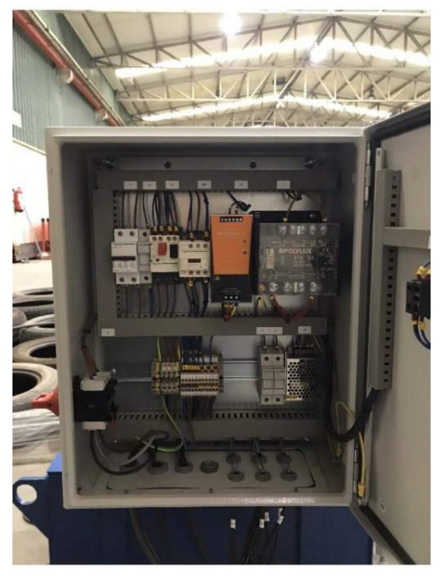
An electrical cabinet, represented in
Figure 8, includes the components that provide power to the hydraulic system by a three-phase electric connection at a voltage of 400 V and nominal power of 4.4 kW. It also contains a residual current circuit breaker to protect the system against short circuit and circuit breakers to limit the effects of an overload.
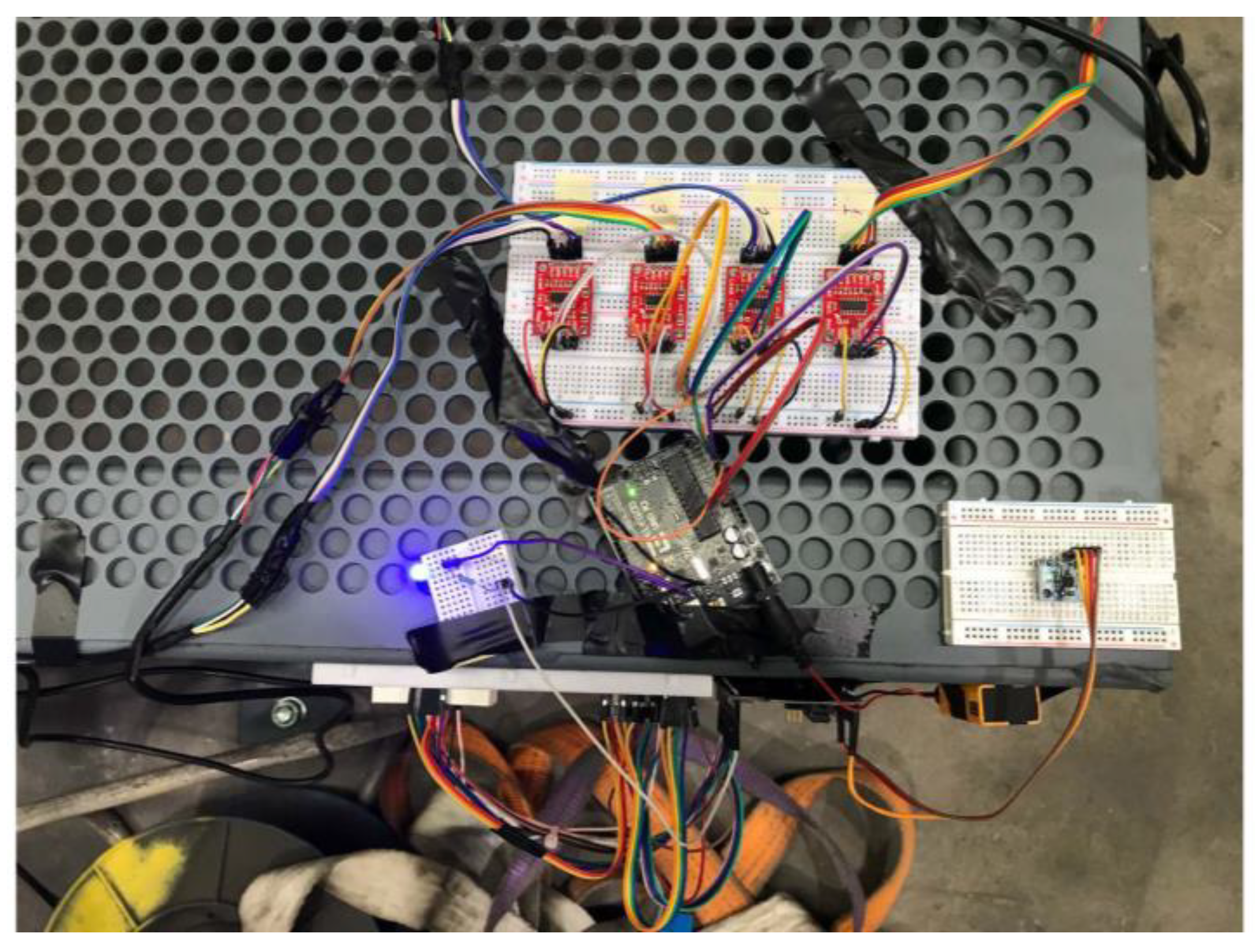
2.6. Electronic Systems Design
The measurement of the rollover angle of the ATV-Quad is performed thanks to two electronic subsystems designed for this project. These subsystems measure the tilt angle of the mobile platform of the test bench and determine the beginning of the vehicle overturn by using the load cells placed under the wheels of the ATV. In addition, another independent electronic subsystem has been designed for the purpose of measuring the damage suffered by the dummy.
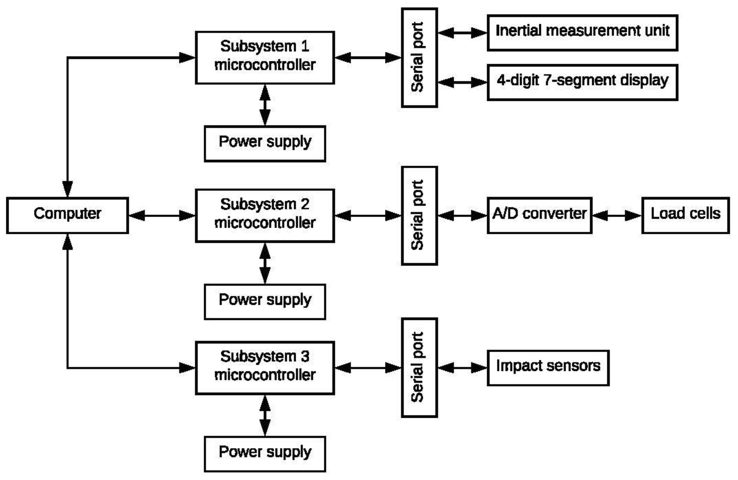
The structure of the complete electronic system has been represented in
Figure 9, where the connections between different components are shown.
The mentioned three electronic subsystems are described in the following.
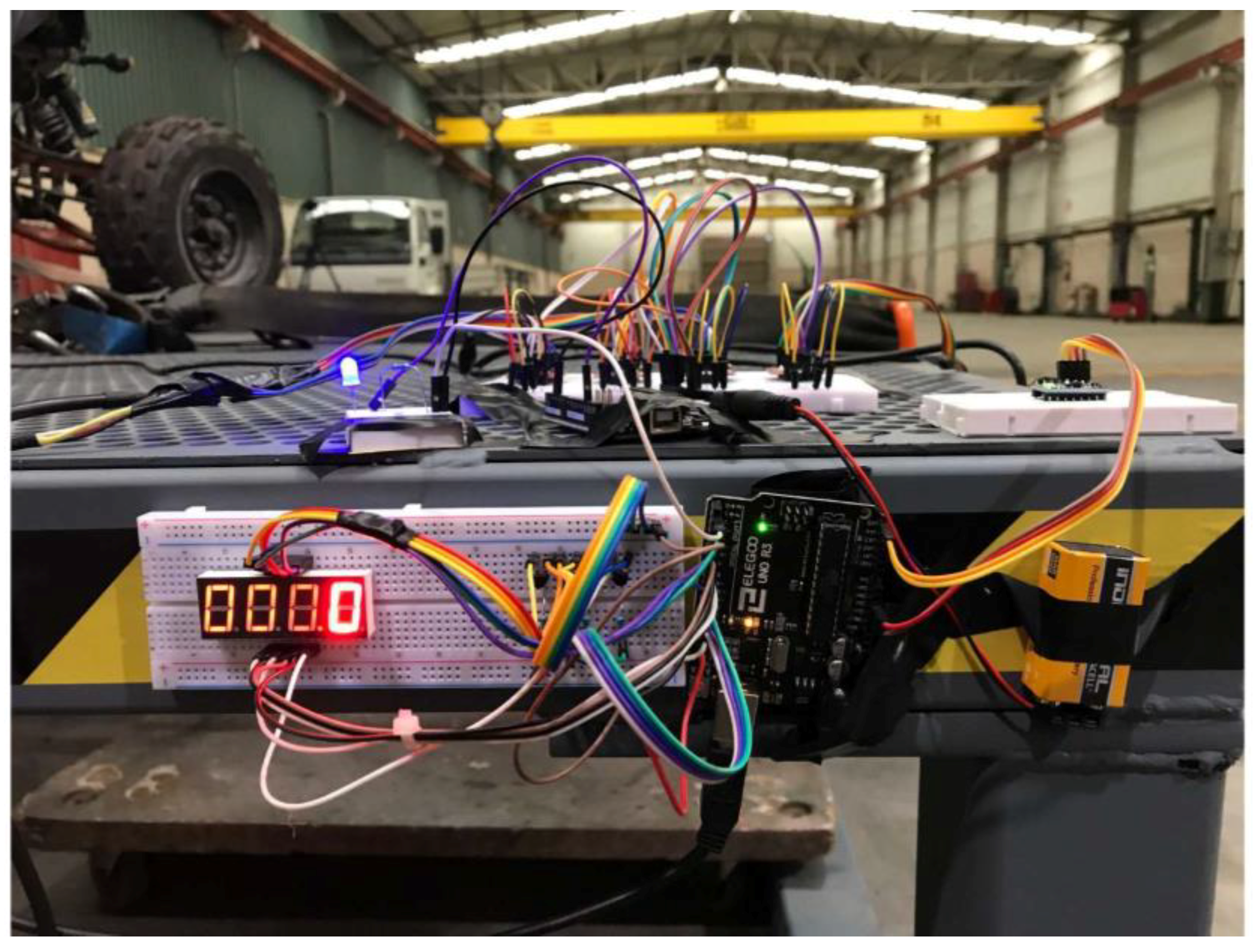
2.6.1. Tilt Angle Measurement
The electronic subsystem that is responsible for the measurement of the tilt angle is based in a microcontroller board.
Figure 9 shows the layout of the system, while
Figure 10 represents its electrical schematic. The components included in this subsystem are described below:
Microcontroller. An Arduino UNO device (Arduino LLC, Boston, MA, USA) has been included, with Input/Output (I/O) ports for the connection of additional electronic components in a modular way. The programming language that has been used is C.
Inertial Measurement Unit (IMU). A MPU6050 has been chosen for this function, since it contains an accelerometer and a gyroscope. This device can sense static and dynamic accelerations and is in charge of measuring the tilt angle. A complementary filter (CF), based in a Kalman filter, has been implemented to filter the noise in the measurement of both the accelerometer and the gyroscope, according to [
17]. The measurement of the tilt angle,
θm,n, with respect to the rotation axis of the mobile platform of the test bench, that corresponds to the instant of time n, has been calculated from Equation (4):
where
βaccel and
agyro are obtained from the measurement of the accelerometer and the gyroscope, respectively. Parameters A and B are weighted coefficients for the application of the CF, where
On the other hand, θm,n−1 is the previous tilt angle calculation to the instant of time, when the present measurement is performed.
4-digit 7-segment display. A display, model 5461AS, has been chosen for showing the tilt angle that has been calculated from the measurements of the IMU. The values of the tilt angle are represented in real time, with a precision of a tenth of a degree, using an algorithm specifically developed for this project.
2.6.2. Rollover Angle Calculation
The rollover test bench has been designed to calculate the rollover angle of vehicles with the characteristics of quads. The calculation of the rollover angle is required to determine the instant of time when the vehicle overturn begins. This second electronic subsystem, whose electrical schematic has been depicted in
Figure 11, has been designed for the purpose of performing the calculations required to solve these problems. The components that have been chosen to configure this subsystem are described in the following paragraphs:
Microcontroller. The board Arduino UNO has been chosen, similarly to the previous electronic subsystem, where the I/O ports have also been used to connect the additional electronic components in a modular way. The programming language has also been C.
Load cells. Four button load cells, model RB-Phi 205, with a load limit of 1000 kg, have been connected to the electronic board. They have been installed on the mobile platform of the test bench (see
Figure 12) in the areas, where the wheels of the tested ATV are placed. In this way, as a test is being performed and the mobile platform rotates, it is possible to determine the instant of time when the pair of wheels that are more distant to the axis of rotation leave the contact with their respective sensors.
A/D converter. The electric signal obtained as output of the load cells is an analog signal; hence, a 24-bit A/D converter, model HX711, has been installed and serially connected to the microcontroller board, using pins clock and data.
2.6.3. Measurement of Damage in a Dummy
This third and last electronic subsystem has been designed to measure the damage suffered by a dummy in a rollover test of an ATV-Quad. The electronic components included in this subsystem are mentioned in the following:
Microcontroller. An Arduino MEGA 2560 board has been chosen for this electronic subsystem. Its I/O ports have been used to connect the sensors in a modular way. In a similar way to the rest of the electronic subsystems, C is the chosen programming language.
Impact sensor. The impact sensors connected to this board, model KY-031, were distributed to areas of the dummy that represent critical points of a human being, such as the head, neck and trunk.
2.7. Control Algorithm Design
Three independent algorithms were developed for the control of the electronic subsystems that are integrated in the test bench. The first of the algorithms is in charge of measuring, calculating, and showing the tilt angle of the mobile platform that supports the tested ATV-Quad. The CF was implemented, following Equation (4), to obtain a measurement less distorted by electronic noise. Additionally, an appropriate refresh frequency of the display was configured to make a real-time representation of the tilt angle possible.
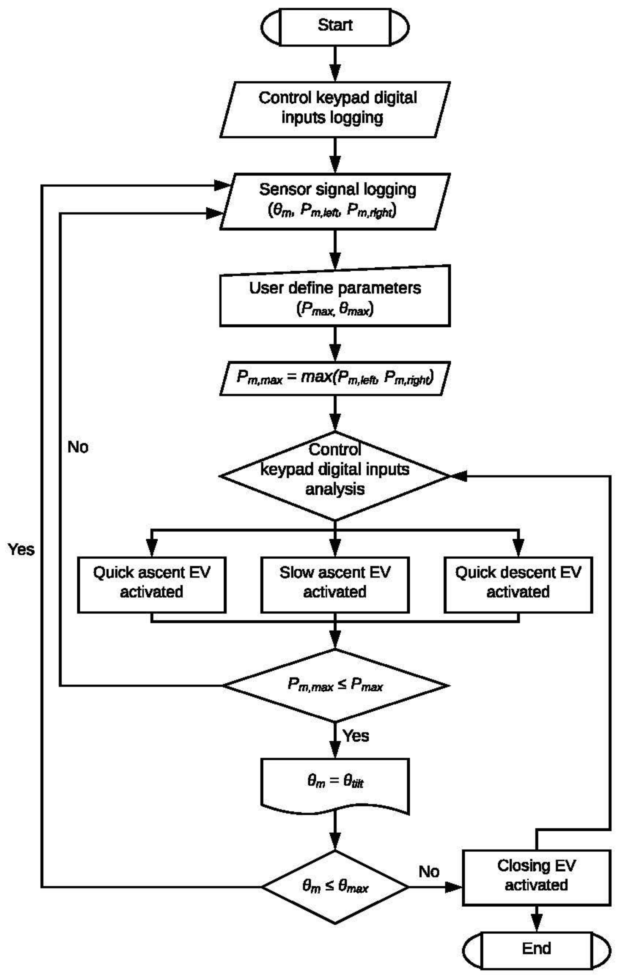
The second of the developed algorithms determines the rollover angle of the vehicle.
Figure 13 shows the flowchart of this algorithm, implemented in an Arduino microcontroller. There are four different stages in the flow control of the algorithm: (i) checking if the signal of the load cells (
Pm,left, Pm,right) is higher than a preset value, given by the user of the bench (
Pmax), meaning that the four wheels of the vehicle stand on the platform; (ii) checking if the signal of the load cells more distant to the axis of rotation of the mobile platform is lower than a preset value, meaning that the wheels over the mentioned cells do not keep contact anymore with their respective cells; hence, the overturn has started; (iii) recording the value of the rollover angle
θtilt, (iv) the mobile platform continues rotating until the maximal value of the tilt angle (
θmax), preset by the user, is reached.
The third and last algorithm developed in this project performs the measurement of the damage suffered by the dummy. A scale of damage was defined to check the values of the acceleration that provide the sensors installed on the dummy. This scale allows one to determine if the damage suffered by the dummy in a rollover test correspond to mild effects or serious, or even fatal, injuries.
2.8. Description of ATV-Quad Rollover Tests
This section addresses the development and execution of a schedule of rollover tests for QBs and AVTs.
In the case of four-wheeled vehicles, the protective elements used for vehicle overturn (at any direction) are a ROPS, and safety belts for the retention of occupants, including the prevention of their partial or complete ejection. The SSVs are designed to provide a ROPS and safety belts with diverse retention degrees. Nevertheless, the QBs, which are active vehicles for the driver, with seats shaped as a saddle, presents a design that does not allow an easy accommodation of a ROPS, safety belt, and retention systems, without a deactivation of this “active driving” feature. For this reason, additional protection measures should be considered for QBs, such as operator protection devices (OPDs).
Five tests were performed with the ATV Yamaha Moto 4250 with a tilt angle of 22.5°, with respect to a horizontal reference on the ground, and a sled length of 3m. The main conclusions of the tests were that for low speed of the sled (5.9–6.6 km/h), the unprotected ATV finished upside down close to the roll center, where the driver could get trapped under the vehicle. As the speed was increased, (7.7–8.6 km/h) the ATV tended to complete a three quarter turn, and its resting position was the opposite one. In addition, tests at high speed were also performed (8.6 km/h) with an installed quad bar (system composed of a fork-shaped ring mounted on a quad, behind the driver, which acts as a safety device against crushing). In the tests, it could be seen that the vehicle stops on the side adjacent to its roll center.
The tests have been performed following a protocol, defined to compare the results of tests without CPD and with Quad Bar installed in the vehicle. A tilting bench was used in each rollover test with an anthropomorphic test device (ATD,
Table 1) or dummy placed in an ATV. A motorbike ATD was used, equipped with sensors, with the purpose of determining the damages caused by the rollover test. The authors concluded that in the static and dynamic tests, the quad bar was not harmful for the stability or dynamic response of the ATV. The authors deduced, as well, that the operator protection devices (OPDs) can be beneficial in low-speed operations. However, they can be dangerous in collisions. The researchers stated that an OPD would be useful for reducing the damage to the driver of an ATV, in the case of an overturn in the workplace. In fact, the quad bar provides enough survival volume in the case of vehicle overturn and provides protection against injuries from crushing and, specially, suffocation due to thoracic compression.
4. Discussion
4.1. ATV-Quad Rollover Tests
In order to verify the successful operation of the complete test bench, some preliminary rollover tests with ATV were performed. Rollover tests with different configurations were developed, such as diverse directions for the overturn, as well as a variety of ATV models from the list in
Table 2.
Once all the electronic, hydraulic, and mechanical systems had been successfully set up and verified, a rollover test schedule was developed. This schedule was defined to include a large number of configurations, such as the mentioned below:
- (a)
Rollover tests were performed in each one of the four possible overturn directions.
- (b)
Two dummies with different anthropometric characteristics were used.
- (c)
The possibility for the ATV to include an empty or full fuel tank was also considered.
- (d)
Additionally, some tests were developed where the dummy was fastened with a safety belt and without it.
- (e)
The safety device automatically deployable ROPS (AIR-ROPS) was installed in the ATV for some of the tests, and set up using diverse configurations, such as folded and inactive, unfolded and inactive, as well as folded and active.
As a result of all the tests, and the subsequent analysis of the obtained data, it was possible to find a significant variation in the rollover angle for different vehicles, with diverse characteristics, and a variety of overturn conditions.
Moreover, it has been proven that the test bench that has been designed, manufactured, and set up in this project, which allows one to perform rollover tests in any of the four feasible orientations, as well as using a variety of ATV models, since the position of the load cells, which support the wheels of the vehicle, can be adjusted to the particular tread and distance between axles of a given ATV.
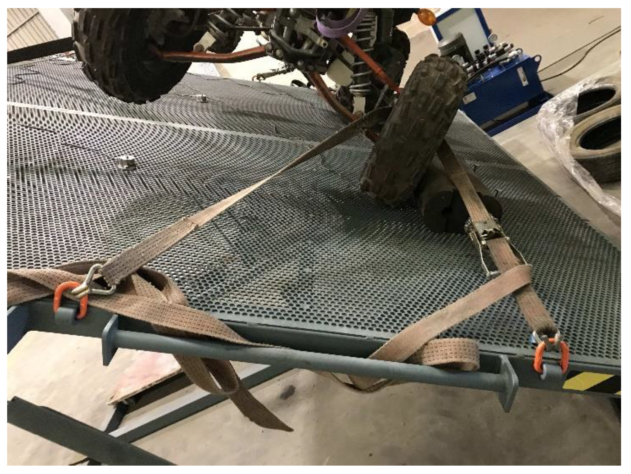
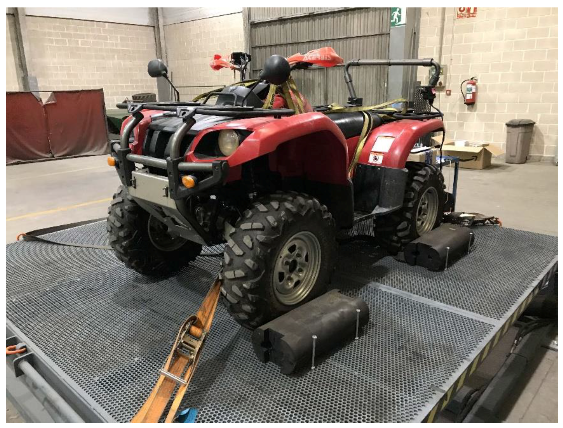
Furthermore, the perimeter fastening system of the platform was able to keep the vehicle on the bench during the non-destructive tests, as it can be seen in
Figure 17.
As a conclusion, it could be stated that the developed bench was validated for the development of rollover tests of the ATV-Quad in different configurations.
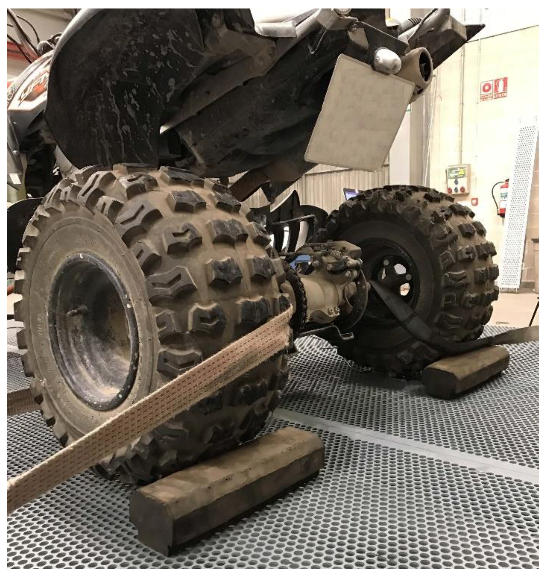
The test bench required the addition of a mechanical element to avoid slippage of the vehicle, as the tilt angle increased in the development of the rollover tests. The friction coefficient between the tires and the perforated sheet on the mobile platform of the bench was not enough to prevent slippage of the vehicle at certain values of the tilt angle. This fact made it impossible to determine the rollover angle in these conditions.
The solution to this problem, as it can be seen in
Figure 18, consisted of two rubber blocks, 10 cm high, beside the wheels of the ATV that are closer to the axis of rotation of the mobile platform. These blocks were anchored to the perforated sheet. Shorter blocks, such as the ones shown in
Figure 19, could not prevent the vehicle from moving over them, once a certain tilt angle was reached during the rollover tests; hence, in these conditions, the rollover angle could not be properly calculated.
4.2. Discussion of the Results of the ATV-Quad Rollover Tests without ROPS
The development of the ATV-Quad rollover tests has resulted in the following data:
- (a)
Test 1a. Rollover angle measurement of an empty ATV-Quad without any dummy.
The ATV-Quad chosen for these tests was a YAMAHA YFM 700R model as produced from the manufacturing facility.
Figure 20 represents the moment when vehicle overturn would be produced in a right side rollover test.
The results, which appear in
Table 3, show a clear difference in the rollover angle between the left side and the right side rollover.
Test 1b. Rollover angle measurement of a full ATV-Quad without any dummy.
In this test, the same ATV-Quad, a YAMAHA YFM 700R model, whose tank had been filled with petrol was used.
As it can be seen from
Table 4, a full ATV-Quad is slightly more unstable than an empty one.
Test 1c. Rollover angle measurement of a full ATV-Quad equipped with a dummy.
In this test, an ATV-Quad YAMAHA YFM 700R, whose tank had been filled with petrol, included a dummy of 78 kg with some accessories.
The tests produced the data represented in
Table 5, showing that the presence of a driver produces a significant variation of the rollover angle at any direction.
Test 1d. Rollover angle measurement of a full ATV-Quad equipped with a bigger dummy.
The dummy used in previous tests was replaced in these tests by a bigger dummy with a mass of 100 kg. The tank was full of petrol.
The values of this test, shown in
Table 6, allow one to deduce that a higher mass of the driver significantly reduces the rollover angle. One consequence is that the amount of clothes and accessories used by the driver could have an influence in the rollover angle.
4.3. Discussion of the Results of the ATV-Quad Rollover Tests with ROPS
A second series of tests were performed to calculate the rollover angle of an ATV-Quad equipped with ROPS. From all the commercial ROPS, an AIR_ROPS was chosen, which remains folded in a normal situation, but it is able to unfold in less than 300 ms in the case of a rollover. In this series of tests, an ATV-Quad YAMAHA GRIZZLY 660 was used.
Test 2a. Rollover angle measurement of an ATV-Quad without a ROPS.
In test 2a, the driver did not use a safety belt.
As it was shown in previous tests, following
Table 7, it can be seen that the presence and dimensions of the driver significantly influences the rollover angle.
Test 2b. Rollover angle measurement of an ATV-Quad without dummy.
The results of the test 2b, which can be seen in
Table 8, show that the presence of a ROPS may slightly influence the angle of rollover.
Test 2c. Rollover angle measurement of an ATV-Quad equipped with a dummy of 100 kg.
In these tests, the driver used a safety belt only if the ATV-Quad was equipped with a ROPS.
The results of the tests 2c, represented in
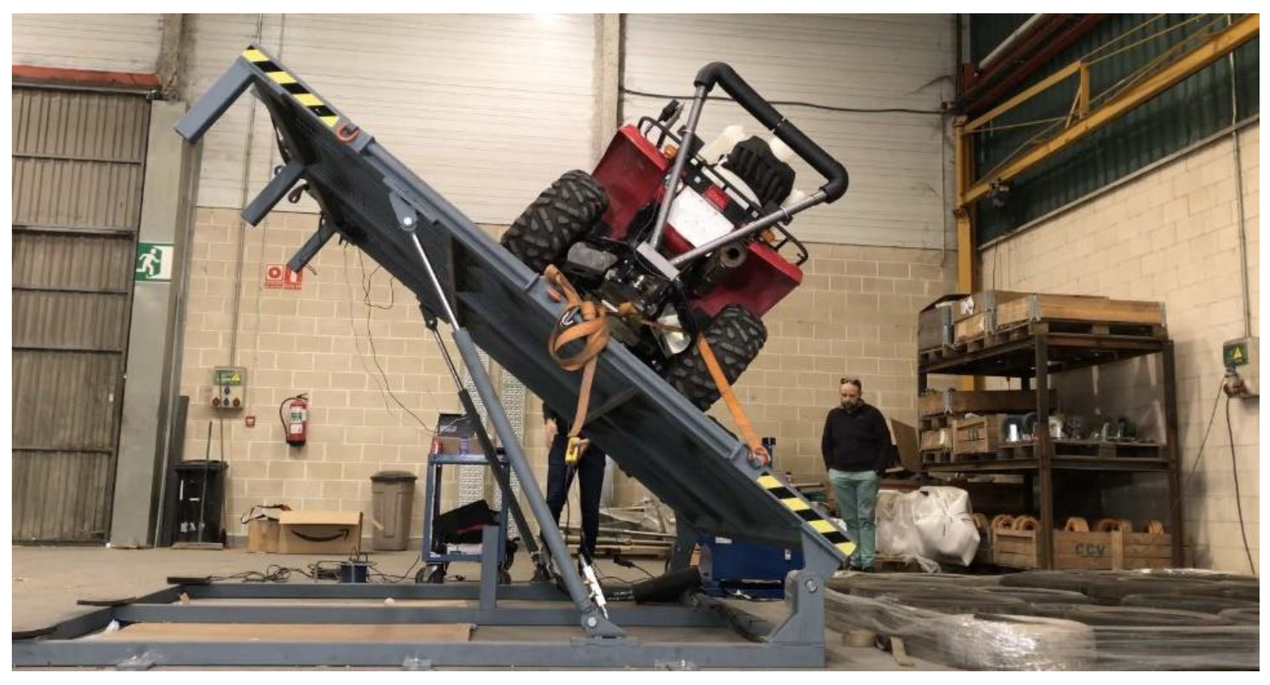
Table 9, show that unfolding the AIR-ROPS decreases the rollover angle, as well as removing it, since the absence of a safety belt produces the slipping of the dummy. A picture of the rollover angle in a right side test of the ATV-Quad can be seen in
Figure 21.
As a result of this second series of tests, it can be concluded that a ROPS in combination with the use of a safety belt may reduce the potential injuries of the driver, as well as increase the rollover angle.
Additionally, the use of an AIR-ROPS increases the rollover angle when compared with the behavior of an ATV-Quad with a conventional ROPS.
5. Conclusions
A rollover test bench was designed, manufactured, and validated for analyzing ATV-Quad overturn in different configurations.
The test bench can reach a speed of tilt angle variation of the tested vehicles from 0.2°/s to 4°/s by the use of hydraulic actuators. It is possible to simulate a static as well as dynamic overturn of an ATV-Quad. Additionally, the test bench allows for the development of tests of vehicle rollover in different directions, since the movable load cells can detect the loose of contact of the wheels of the vehicle with the bench mobile platform at any direction of the overturn.
The performance of the test bench was successful, since it allowed for the development of several ATVs, equipped with a dummy, in a variety of configurations. In particular, it was possible to assess the effectivity of the automatically deployed ROPS (AD-ROPS) system, regarding the protection of the driver of the vehicle.
As a future research line regarding the rollover test bench presented in this manuscript, a study of the rollover of hospital stretchers and wheelchairs that are transported in ambulances will be carried out. Another advantage offered by the test bench is its low cost, relatively low weight and therefore the possibility of being able to transport it easily.


 ,
, 


