Featured Application
A simplified graphical method is proposed to represent the generic connections among the mechanical units of the hybrid systems with the continuously variable units. An example with wider ratio coverage and higher torque capacity is provided.
Abstract
To increase the energy efficiency of road vehicles, an ideal transmission system should have a wide ratio coverage, a high torque capacity, and a high mechanical efficiency. Continuously variable units (CVUs) have been successfully implemented due to the smooth ratio variation, sufficient torque capacity, and ratio coverage. Hence, it will be beneficial to develop a hybrid powertrain comprising a CVU. In this paper, a design method called the “basic path diagram” (BPD) is proposed. It provides a simplified schematic of the system and represents the generic connections among the mechanical components. The system configurations synthesized by the BPD can be sorted according to three characteristics: Direction of power flows through the CVU, coupling pattern of the power inputs, and number of transmission paths parallel to the CVU. The first characteristic determines the number of times the CVU ratio coverage can be exploited, the second characteristic determines whether the torque of the power inputs can be independently controlled, and the third characteristic can help reduce the torque loading of the CVU. With the aid of a BPD, one of the possible system configurations is provided as an example. The result shows that the system can exploit twice the ratio coverage of the CVU and reduce the torque and power transmitted by the CVU in combination with planetary gearsets.
1. Introduction
One of the development goals for modern road vehicles is to enhance energy efficiency and reduce emissions. The powertrains usually combine multiple power inputs, such as internal combustion engines (ICEs) and electric motors/generators (M/Gs), to improve fuel economy. The role of the transmission system is to match the varying road resistance with the torque and the power characteristics of different power sources. Therefore, an ideal transmission should have a wide ratio coverage, a high torque capacity, and a smooth ratio variation to fulfill the requirements of efficiency and shifting quality.
The V-belt continuously variable unit (CVU) has been widely applied in both on-road and off-road vehicles due to its light weight, mechanical simplicity, and seamless ratio variation. [1,2,3,4] The variator of the V-belt CVU comprises a metal or rubber V-belt and two pulleys. The torque is transmitted by the traction between the V-belt and the two sheaves of the pulleys. Its ratio coverage and torque capacity have been proven sufficient for various road vehicles, which range from sport scooters and all-terrain vehicles (ATVs) with rubber V-belts to full-size sedans and sport utility vehicles (SUVs) with metal V-belts. Therefore, it is beneficial to develop a hybrid system based on the V-belt CVU.
In this paper, 28 hybrid systems with V-belt or hydrostatic CVU [5,6,7,8,9,10,11,12,13,14,15,16,17,18,19,20,21,22,23,24,25,26,27,28,29,30,31] have been studied. Their application cases vary from scooters, passenger cars, to buses and unmanned aerial vehicles. Among the majority of them [5,6,7,9,10,14,19,20,23,24,25,26,27,31], the second power input is connected to the driveline directly or via clutches. The CVUs of four systems [15,29,30] are connected after the electric variable transmissions (EVTs or e-CVTs) formed by two power inputs connected together via a planetary gearset(s). The CVUs of six systems [5,8,13,16,21,22] are coupled with planetary gearsets, and the arrangement forms a power-split device which can reduce the torque load of the CVU [32,33,34]. Three systems [10,11,12,17,18] can exploit twice the ratio coverage of the CVU by transmitting the power through the CVU in opposite directions in different driving modes with the aid of clutches and gearsets. To efficiently analyze the topological structures and the characteristics of the hybrid systems with CVUs, there is a need for a simple and generic graphic method.
In the three systems mentioned in [10,11,12,17,18], although the total ratio coverages are increased by the dual-way manipulated CVUs, the power is transmitted solely by the CVUs during the continuously variable ratio modes. Their torque capacities are still limited by the maximum allowable torque of their CVUs. In the researches done by Beachley [32,33] and Hsieh [34], the CVU can be combined with a planetary gearset, forming a power-split mechanism with a constant ratio path parallel to the CVU. The torque loading of the CVU can be shared by the constant ratio path, so the torque capacity of the system is higher than that of the CVU. However, as a trade-off, the overall ratio coverage of the system is less than that of the CVU [32]. Therefore, if the dual-way manipulated CVU and the power-split feature can be combined together, a hybrid system can have both a wider ratio coverage and higher torque capacity. Hence, a systematic process is required to synthesize the complex layout of the system.
In this paper, a graphical method called the BPD is proposed to display and synthesize the topological layout of powertrain systems. The key characteristics of the system and their required conditions in the BPD are then identified. With the aid of BPD and the identified characteristics, the previous 28 hybrid systems are classified. With the BPD method, a new system suitable for heavier-duty application will be synthesized, with the features which the previous 28 systems cannot achieve.
2. Basic Path Diagram (BPD)
Due to the complexity of the mechanism, developing the structure of the system with a simplified topological diagram is easier and more efficient than using a complete mechanical schematic. The graphical method, BPD, in this paper applies blocks and lines to represent the connection among the units of the system. The procedure for developing the BPD will be described in this chapter.
2.1. Function Power Graph (FPG)
The FPG is a graphical method developed by Chen [35] that represents the connection of clutches, brakes, and gearsets between power sources and outputs. The units are linked by connection lines, and multiple connection lines are joined by coupling points. For hybrid powertrains with multiple drive modes, the transmission path of power flow under different modes can be clearly described by the FPG.
The FPG must show the complete connection of powertrain units with multiple types of gearsets, clutches, and brakes. Some of these units and transmission paths may only be activated when the vehicle is reversing and are always idle when the vehicle is not in the reverse gear. Some of these units and transmission paths may only allow the power to flow within the system, such as starting the ICE with the M/G or driving the M/G with the ICE to recharge the battery. Therefore, the graph will become too complicated to assess all of the possible power paths of an existing system. This complexity limits the ability of the designer to enhance the overall energy efficiency of the system by further developing additional drive modes.
2.2. BPD
To provide a systematic method to simplify the FPG, another graphical method called the BPD is proposed in this paper. There are only seven kinds of powertrain elements, named “basic units”, as listed in Table 1. Other elements that are represented in the FPG will be ignored or combined with basic elements during the process of conversion from FPG to BPD.

Table 1.
List of basic units in the basic path diagram (BPD).
The main purpose of the BPD is to represent the available power flow paths of a powertrain system and to exclude unrelated units present in the FPG. The conversion from FPG to BPD can be achieved by performing the following steps:
- Rename the power input unit in the FPG as IN1, IN2, IN3…, etc., in sequence of their maximum power output if there are multiple power sources.
- Ignore the independent subsystems that have no connection with other transmission paths and are driven by a single power source. For example, the rear wheels of a vehicle are independently driven by an e-Axle module. This e-Axle module is purely powered by electric motor(s) and has no connection with other powertrain units such as the engine and the transmission. Hence, this e-Axle module needs to be completely ignored in this step.
- Ignore the auxiliary power input units that have no mechanical connection to the wheel or are unable to drive the wheel directly. Examples include electric motors that accelerate the flywheel to recharge its kinetic energy and superchargers that are driven by electric motors.
- Ignore all of the clutches, brakes, couplings, and torque converters.
- Ignore transmission units that have constant ratios or have step-variable ratios. These include gear trains, chain drives, belt drives, manual transmissions (MTs), automatic transmissions (ATs), and dual-clutch transmissions (DCTs).
- If there are gearsets with multiple DOFs, such as planetary gearsets, differentials, and Ravigneaux gearsets, replace them with 2DOF-3E, 2DOF-4E, and MDOF.
- Locate the transmission paths that are only used for reversing and combine them with the transmission paths for low-gear forward drive.
- Combine the coupling points into adjacent basic units, such as IN, OUT, and CVU.
- Combine the remaining coupling points with adjacent ones.
- Adjust the orientation of the basic units, and avoid overlap and intersection of the connection lines that are parallel in the original FPG.
Here, the hybrid system proposed by Eindhoven University of Technology (Technische Universiteit Eindhoven, TU/e) [11,12] is given as an example of the BPD. A schematic diagram of the mechanism is shown in Figure 1. According to [35], the FPG for this system is shown in Figure 2a. There are seven gear drive units and six clutches, including a sliding gear mechanism for reverse that is considered as one of the clutches. The BPD for this system is shown in Figure 2b, with the transmission path for the reverse drive (Cr and Gr) merging with that for the low-speed forward drive (Cep, Ge, and Gfp2).
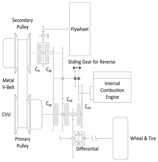
Figure 1.
Schematic diagram of the hybrid system proposed by TU/e [11,12].
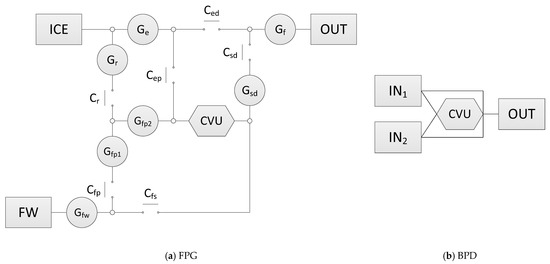
Figure 2.
FPG and BPD of the TU/e system.
3. Classification of Systems
A hybrid system is formed by combining two or more power input units with different power and torque characteristics with respect to the rotational speed. To match the varying road resistance, the system needs to be manipulated in different driving modes so that each power input can work in its high-efficiency region. Different driving modes usually have diverse power flow patterns through the mechanical units of a system. Thus, by analyzing the layout of the BPD for this system, the power flow patterns and characteristics of the system can be specified.
To systematically specify the power flows of the synthesized BPD, the system can be sorted by the following three properties: Direction of power flows through the CVU, coupling pattern of the power inputs, and number of power transmission paths parallel to the CVU.
3.1. Direction of Power Flows through the CVU
CVUs are transmission units with seamlessly variable ratios and two shafts for power input and output. During normal driving situations, the power from the input(s) passes forward through the CVU. During either engine braking or regenerative braking, the power from the wheel(s) passes backward through the CVU to the input(s) within a limited time interval. In this paper, when analyzing the direction of power flows through the CVU, only normal driving situations are taken into account since the power passing through the CVU is continuous rather than intermittent. Additionally, the situations in which the power only transfers within the system, such as when the M/G starts the ICE through the CVU or when the ICE drives the M/G through the CVU for recharging, are ignored. In every driving mode, the power passing through the CVU to the wheels is unidirectional. The system is called a one-way manipulated system.
Alternatively, if the input shaft and output shaft of the CVU can be interchanged in different driving modes, this kind of system is called a dual-way manipulated system, as the power passing through the CVU to the wheels is bidirectional. As shown in Figure 3, the power flows through the CVU from node A to node B in mode 1 and then from node B to node A in mode 2. Since the ratio coverage of the CVU is exploited twice, this feature can help increase the overall ratio coverage of the system by combining other transmission units such as clutches and gearsets.
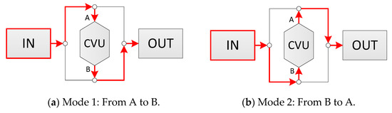
Figure 3.
Power flow for a dual-way manipulated system in different modes.
In the BPD of a dual-way manipulated system, the CVU is at the center of a bidirectional bridge structure, as shown in Figure 4. This structure is required so that the two ends of the CVU can be connected to both the output and the input unit through connection lines. For hybrid systems with multiple input units, the two ends of the CVU can be connected to all of the inputs or to only one of them. Figure 5 shows a few examples of bidirectional bridge structures in different systems.
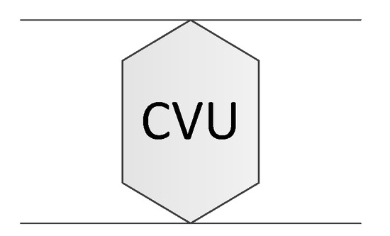
Figure 4.
Bidirectional bridge structure in a BPD.
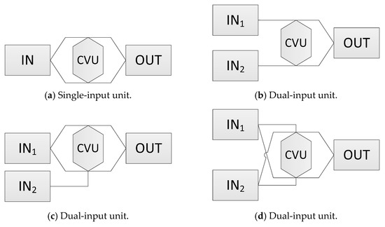
Figure 5.
Examples of systems with bidirectional bridge structures.
3.2. Coupling Pattern of Power Inputs
If the power flows from two input units are coupled together on a shaft, a clutch, a brake, or any one-DOF mechanism, the system is called a direct-coupled system, as shown in Figure 6. At the coupling point, the rotational speeds of the two power flows are equal, and the output torque is the summation of the two. Therefore, the system is a torque coupler. The speeds of the inputs have a constant relationship caused by the mechanical parameters of the system, and the input torques can be independently controlled.
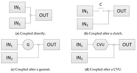
Figure 6.
Examples of direct-coupled systems with two input units.
If the two power flows are merged together on the two elements of a multi-degree-of-freedom (MDOF) mechanism, such as a planetary gearset or a differential, the system is called a planetary gear-coupled system. In the BPD, the input units are connected directly to the different nodes of an MDOF unit, as shown in the examples in Figure 7. The rotational speed and torque of the output are determined by the gear ratio of the planetary gearset. The system is a speed coupler, due to the fact that the speeds of the power inputs can be independently controlled. On the other hand, the steady-state torque distribution among the inputs and the output is constant, and is constrained by the parameters of the system. For a planetary gear-coupled system with two power inputs, if only one input is powering the system, the other idle input needs to be locked-up by a brake or the powering input will result in driving the idle input rather than the system output(s).
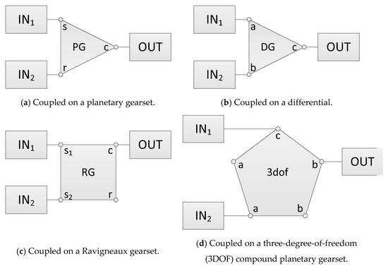
Figure 7.
Examples of planetary gear-coupled systems.
3.3. Number of Power Transmission Paths Parallel to the CVU
If every input unit in the hybrid system has a unique transmission path with no transmission path parallel to the CVU, the system is called a single-path system. Figure 8 shows four examples of single-path systems with different coupling patterns and transmission units. Since there is no transmission unit parallel to the CVU, the ratio coverage of the system is equivalent to that of the CVU if there is no other transmission unit with a variable ratio.
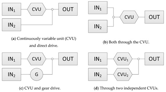
Figure 8.
Examples of single-path systems.
Most of the studied hybrid systems [5,6,7,8,9,10,11,12,13,14,15,16,17,18,19,20,21,22,23,24,25,26,27,28,29,30,31] have no transmission mechanism parallel to the variator. This means that the power flow from the power source(s) must pass through the CVU. Therefore, the maximum allowable torque and power of the system are also confined by the CVU. If at least one transmission path is parallel to the CVU and at least one input unit can drive the wheel(s) through both of them, the system is called a dual-path system. However, if the above parallel transmission path allows the power to transfer only within the system, such as starting the ICE with the M/G or driving the M/G by the ICE for recharging, the system will not be considered a dual-path system.
3.3.1. Power-Split-Type Dual-Path Systems
According to the combination pattern of the CVU and the constant ratio path, a dual-path system can still be sorted into two subtypes: Power-split-type dual-path system and bypass-type dual-path system. For a power-split-type dual-path system, the power is transmitted through the CVU and the constant ratio path simultaneously with the aid of a 2DOF mechanism. Therefore, the input torque is shared by the CVU and the constant ratio path, and the maximum allowable torque of the system can be higher than that of the CVU. If the power is split off at the 2DOF mechanism and coupled directly after the CVU, the system is called an output-coupled system, as shown in Figure 9b. On the other hand, if the power is split off directly after the input and coupled together at the 2DOF mechanism, the system is called an input-coupled system, as shown in Figure 9a.
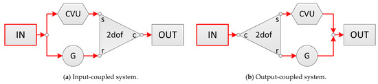
Figure 9.
Power flows in power-split-type dual-path systems.
In the BPD, power-split-type dual-path systems have a loop structure comprising connection lines, a CVU, and a MDOF unit, such as 2DOF-3E in Figure 10. The actual ratio range of the system can then be set by combining other transmission units, such as gearsets, which are ignored in the BPD.
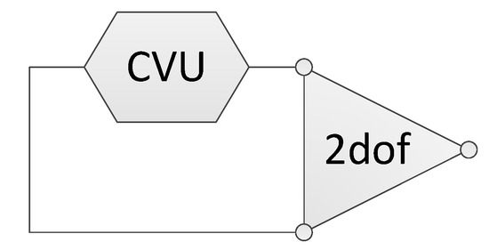
Figure 10.
Example of a loop structure for power-split-type dual-path systems in the BPD.
3.3.2. Bypass-Type Dual-Path Systems
For a bypass-type dual-path system, the power is transmitted by either the CVU or the constant ratio path. The power cannot be transmitted through both simultaneously unless the ratios of the CVU and the constant ratio path are exactly the same. As shown in Figure 11a, the power is transmitted through the constant ratio path (gear drive) with higher efficiency and higher torque capacity. In Figure 11b, the power flows through the CVU with a seamlessly variable ratio. This kind of system does not need an MDOF mechanism to split or merge the input power but requires clutching or braking to direct the power through the CVU or through the constant ratio path. Therefore, during the CVU drive mode, the maximum allowable torque of the system is still confined by the CVU. The system ratio coverage is the same as that of the CVU if the ratio of the constant ratio path does not exceed that of the CVU.
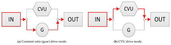
Figure 11.
Power flow in a bypass-type dual-path system under different drive modes.
In the BPD, bypass-type dual-path systems have a loop structure comprising only connection lines and a CVU, as shown in Figure 12. In this configuration, there is another transmission path parallel to the CVU, and they are joined together directly. The actual ratio of the system can be set by combining clutches, brakes or gearsets, which are ignored in the BPD.
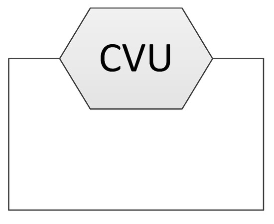
Figure 12.
Example of loop structures for bypass-type dual-path systems in the BPD.
3.4. Summary of System Classification
Among the three properties of the system, the first property, the direction of power flows through the CVU, determines the ability of the system to exploit the ratio coverage of the CVU. The third property, the number of power transmission paths parallel to the CVU, determines whether the system can share the torque load passing through the CVU with other transmission paths. The above two properties of the system can be identified by the connection pattern of the connection lines around the CVU: A bidirectional bridge structure for dual-way manipulated systems and a loop structure for dual-path systems. Therefore, the existence of the bidirectional bridge structure and the loop structure is the required condition for the system to exploit twice the ratio coverage of the CVU and reduce the torque load of the CVU with other mechanisms. Proper clutch and gearset arrangements are still required to provide the two features.
The required structures for dual-way manipulated systems and the two types of dual-path systems are listed in Table 2. When synthesizing the BPD of a desired system, the required structures need to be selected first and then combined with other basic units, which are linked by connection lines. The complete layout of the system in the FPG can then be formed by adding clutches and gearsets into the BPD. In the example shown in Table 3, the BPD of a one-way manipulated, direct-coupled, and bypass-type dual-path system is synthesized in the beginning. The complete layout of the system is presented by the FPG after adding other units, such as coupling points, clutches, and a gearset, into the BPD.
Table 2.
Required structures of dual-way manipulated systems and dual-path systems.
Table 3.
Example of synthesizing a system with a BPD.
4. Analysis of Hybrid Systems with CVUs
For simplicity, the above three system characteristics can be expressed by three letters, as shown in Table 4. The first letter denotes the direction of CVU manipulation: “O” for one-way manipulated systems and “D” for dual-way manipulated systems. The second letter denotes the power coupling pattern: “D” for direct-coupled systems and “P” for planetary gear-coupled systems. The third letter denotes the number of transmission paths parallel to the CVU: “S” for single-path systems and “D” for dual-path systems. For example, a “D-D-D” system has a dual-way manipulated CVU and directly coupled power input units and is a dual-path system.
Table 4.
Syntax of system categories.
By combining the above three characteristics, the structures of the 28 studied hybrid systems [5,6,7,8,9,10,11,12,13,14,15,16,17,18,19,20,21,22,23,24,25,26,27,28,29,30,31] can be classified into eight different categories, as shown in Table 5. Most of the current systems are O-D-S systems, whereas D-P-S and D-P-D are both null sets. There are only three dual-way manipulated systems: D-D-S and D-D-D systems.
Table 5.
List of hybrid systems with CVUs.
The BPDs of the three dual-way manipulated systems are shown in Figure 13. The three systems all have bidirectional bridge structures, which are highlighted in red. Therefore, the power flow can be transmitted through the CVU in opposite directions under different driving modes. The system proposed by General Motors (GM) and TU/e has two loop structures, whereas the TUM system has only one loop. Although the GM system is a single-path system (D-D-S), the existence of the loop structure shows the possibility of it being redesigned as a dual-path system under proper clutch and gearset arrangement. The other two D-D-D systems, which were proposed by TU/e and TUM, are both bypass-type dual-path systems due to the absence of MDOF units in their loops. The torque is transmitted solely by the CVU during the seamlessly variable ratio modes. Therefore, the transmitted torque of the system cannot exceed the maximum allowable torque of the CVU or it will cause damage to the CVU, such as belt slippage for a V-belt CVU or transmission fluid leakage for a hydrostatic CVU.

Figure 13.
BPDs of the three dual-way manipulated systems, wherein the bidirectional bridge structures are highlighted in red. (a) General Motors two-mode concept (1986) [10]. (b) TU/e (1987) [11,12]. (c) Technical University of Munich (2006) [17,18].
5. System Synthesis and Example
To fulfill the need for both greater ratio coverage and torque capacity, a hybrid system will be designed with the aid of a BPD. To provide wider overall ratio coverage than the CVU, the new system is designed to be dual-way manipulated. To allow a higher torque capacity than the CVU during all continuously variable ratio modes, it is set to be a power-split-type dual-path system. The coupling pattern of the two input units can be either direct coupled or planetary gear coupled. Therefore, the category of the new system will be D-D-D or D-P-D.
Section 3.1 showed that a bidirectional bridge structure is a requirement of a dual-way manipulated system, as shown in Figure 4. For a power-split-type dual-path system explained in Section 3.3.1, a loop structure comprising a CVU and an MDOF unit is required, as shown in Figure 10. To reduce the mechanical complexity, only 2DOF-3E and 2DOF-4E are taken into account in this paper. In Figure 14, four possible basic structures are formed by combining a bidirectional bridge and a loop structure. Among them, those shown in (a–d) are single-loop structures, whereas those in (e–h) are double-loop structures.
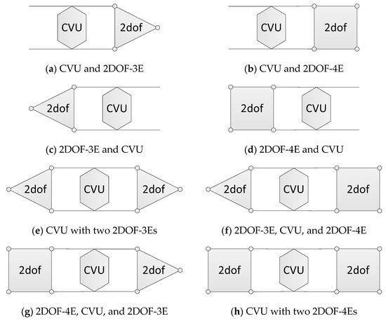
Figure 14.
Possible basic structures of the system.
The hybrid system has two inputs and one output. Therefore, by adding them to the structures shown in Figure 14, the complete BPD of the target system can be formed. To attain the goal of wider ratio coverage, higher torque capacity, and a continuously variable ratio, the system design follows the three principles below:
- The system has at least two driving modes, and each of them is driven by one of the two inputs.
- In every driving mode, the power is transmitted by the power-split mechanism formed by the loop structure comprising the CVU and the 2DOF unit to have a higher torque capacity than the CVU.
- The transition between the two driving modes should be seamless. At the mode switching point, the CVU ratios in the two modes need to be the same. Therefore, the ratio range of the two modes should be joined together or have a small overlap region.
To fulfill requirement (3), the system requires two loop structures, and each of them is used to transmit power in the two driving modes. As a result, only the four double-loop structures in Figure 14 e–h can be considered. In combination with different connection patterns among gearsets, inputs and output, various possible results can be generated. To demonstrate the effect of the synthesized system in a more understandable way, the BPD in Figure 15 is chosen as an example. The layout is based on the double-loop structure in Figure 14e, and its possible power flow patterns are shown in Table 6.
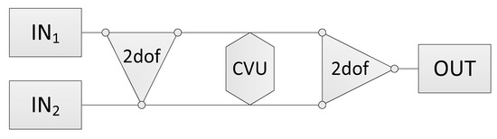
Figure 15.
BPD of the synthesized system.
Table 6.
Possible power flow patterns of the synthesized system.
To direct the power through the designed paths and adjust the ratio spans of different driving modes, the next step is to determine the position of the clutches and gearsets and the ratio of the gearsets. The result can be found through a global search method. One of the feasible solutions is shown in Figure 16. A M/G is used as IN1 for low- to medium-speed driving, whereas an ICE is used as IN2 for medium- to high-speed driving. The parameters of the example are shown in Table 7.

Figure 16.
FPG of the synthesized system developed by a BPD.
Table 7.
Parameters of the synthesized system.
The synthesized system has two main driving modes: Electric mode and engine mode, as shown in Figure 17 and Figure 18 respectively. In the electric mode, the input power of the M/G is split into two by planetary gearset PG1. The two power flows are transferred by the CVU and gearset G1 simultaneously and then merged before entering gearset G2 and locked-up planetary gearset PG2. The ratio of the torque entering the CVU, Tr1, and the torque entering gearset G1, Ts1, can be determined by the ratio of planetary gearset PG1.
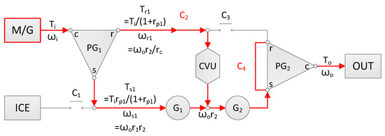
Figure 17.
Relation of torque and speed under the electric mode.
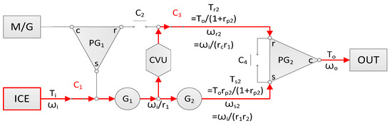
Figure 18.
Relation of torque and speed in the engine mode.
Therefore, only 74% of the torque load is carried by the CVU regardless of the ratio of the CVU. The fraction of input power passing through the CVU is expressed as follows:
The system ratio under the electric mode is expressed as follows:
In the engine mode, the input power of the ICE is split into two after gearset G1. The two power flows are transferred by the CVU and gearset G2 and then merged together on planetary gearset PG2. The ratio of the torque passing through the CVU, Tr2, and the torque passing through gearset G2, Ts2, can be determined by the ratio of planetary gearset PG2.
For the electric mode, only 74% of the torque load is carried by the CVU regardless of the CVUs ratio. The fraction of the input power passing through the CVU is expressed as follows:
The system ratio under the engine mode is expressed as follows:
Based on the above two driving modes, there are six available modes in total, including the electric mode with engine starting, the engine mode with recharging, and two hybrid modes. The driving modes that the system can achieve and their power flow patterns are listed in Figure 19.
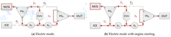
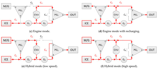
Figure 19.
Power flows of the synthesized system under different modes.
6. Results
With the aid of BPD, a dual-way manipulated, direct-coupled, and power-split dual-pathed system is synthesized. The three features do not exist simultaneously in the 28 studied systems [5,6,7,8,9,10,11,12,13,14,15,16,17,18,19,20,21,22,23,24,25,26,27,28,29,30,31]. In the two planetary gearsets (PG1 and PG2) of the system, the tooth ratios of the ring gears to the sun gears (rp1 and rp2) are both 0.35. According to Equations (1) and (4), the CVU always transfers 74% of the torque load due to the absence of the varying CVU ratio, rc, in the two equations. Hence, the torque capacity of the system is greater than the maximum allowable torque of the CVU. In Figure 20, the overall ratio coverage of the system is 10.38, whereas the ratio coverage of the CVU is only 4.0. Mode switching is performed when the system ratio is 1.0 in both modes. Therefore, the ratio coverage of the system is increased by 159.5%, and the ratio variation remains continuous. Moreover, the ratio of the power passing through the CVU and the total input power varies from 74% to 92% according to the ratio of the CVU, as shown in Figure 21. The synthesized system with wider ratio coverage and higher torque capacity can help increase the energy efficiency of road vehicles.
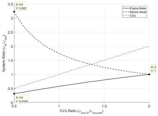
Figure 20.
Ratio variation of the electric mode, the engine mode, and the CVU.
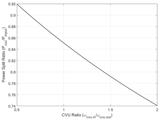
Figure 21.
Power split ratio of the synthesized system.
7. Conclusions
Properly arranging the transmission paths and units allows the system to provide a wider ratio coverage and higher torque capacity than a CVU, while still possessing continuous ratio variation.
To develop the complex mechanical structure of the system, a graphical method called the BPD is first proposed. The method is based on the FPG [35]. After simplifying the system elements and the transmission paths, there are only seven basic elements involved in the BPD, and the generic connection among different elements is shown. The system synthesized by the BPD can be sorted into eight categories based on the following three properties concerning the connections among the power sources, the CVU, and the MDOF units.
- Direction of power flows through the CVU: One-way manipulated and dual-way manipulated systems. A bidirectional bridge structure comprising the CVU is required in the BPD for a dual-way manipulated system, which can exploit twice the ratio coverage of the CVU.
- Coupling pattern of the power inputs: Direct-coupled and planetary gear-coupled systems. The power sources of a planetary gear-coupled system are connected to different elements of an MDOF unit.
- Number of power transmission paths parallel to the CVU: Single-path, bypass-type dual-path, and power-split-type dual-path systems. In the BPD, a loop structure comprising only the CVU is required for a bypass-type dual-path system. For a power-split-type dual-path system, the loop structure should comprise a CVU and an MDOF unit.
With the aid of the BPD, a hybrid CVT system with dual-way manipulation and power-split-type dual-path features is developed. The required structure of a dual-way manipulated system is a bidirectional bridge structure comprising the CVU. A power-split-type dual-path system must have at least one loop structure comprising a CVU and an MDOF unit. The possible combinations are first listed, and one of them is selected as an example. With proper parameters, the synthesized system can provide a wider ratio coverage by exploiting twice the ratio coverage of the CVU. During all continuously variable ratio modes, the torque transmitted through the CVU is reduced due to the power-splitting principle.
In the given example, the overall ratio coverage of the synthesized system is 159.5% higher than that of the CVU. The CVU transmits only 74% to 92% of the input power and 74% of the torque load. The ratio variation of the system also remains continuous during mode switching. Therefore, a system with a wider ratio coverage and a higher torque capacity can help increase the energy efficiency of road vehicles.
Author Contributions
Conceptualization, H.-Y.K.; Methodology, H.-Y.K.; Project administration, T.L.; Supervision, T.L.; Writing–original draft, H.-Y.K. All authors have read and agreed to the published version of the manuscript.
Funding
This research received no external funding.
Data Availability Statement
No new data were created or analyzed in this study. Data sharing is not applicable to this article.
Acknowledgments
This study has been supported by Giant Lion Know-How Co., Ltd., which is gratefully acknowledged by the authors.
Conflicts of Interest
The authors declare no conflict of interest.
References
- Global Automotive Transmission Type Market Share between 2015 and 2025. Available online: https://www.statista.com/statistics/204123/transmission-type-market-share-in-automobile-production-worldwide/ (accessed on 25 February 2021).
- Automotive Transmission Market Size Worth $281.3 Bn by 2026. Available online: https://www.gminsights.com/pressrelease/automotive-transmission-market (accessed on 25 February 2021).
- Automotive Automatic Transmission Market—Growth, Trends, COVID-19 Impact, and Forecasts (2021–2026). Available online: https://www.mordorintelligence.com/industry-reports/automotive-automatic-transmission-market (accessed on 25 February 2021).
- Automotive Transmission Market, Size, Share, Opportunities and Forecast, 2020–2027. Available online: https://www.datamintelligence.com/research-report/automotive-transmission-market (accessed on 25 February 2021).
- Dugger, G.L.; Brandt, A.; George, J.F.; Perini, L.L. Flywheel and flywheel/heat engine hybrid propulsion systems for low-emission vehicles. In Proceedings of the Intersociety Energy Conversion Engineering Conference, Boston, MA, USA, 3–5 August 1971. [Google Scholar]
- Frank, A.; Beachley, N. Improved fuel economy in automobiles by use of a flywheel energy management system. In Proceedings of the 1975 Flywheel Technology Symposium, Berkeley, CA, USA, 10–12 November 1975; Available online: https://apps.dtic.mil/sti/pdfs/ADA301672.pdf#page=83 (accessed on 11 January 2021).
- Loscutoff, W.V. Flywheel/Heat Engine Power for an Energy-Economic Personal Vehicle; Battelle Pacific Northwest Labs.: Richland, WA, USA, 1976. [Google Scholar] [CrossRef]
- Hagin, F.; Merker, P. Drive systems with brake-energy recovery. In Proceedings of the First International Automotive Fuel Economy Research Conference, Washington, DC, USA, 31 October–2 November 1979; pp. 416–423. Available online: https://trid.trb.org/view/184357 (accessed on 11 January 2021).
- Greenwood, C.J. Integration of a Commercial Vehicle Regenerative Braking Driveline, C191/86, IMechE 86; Leyland Vehicles: Leyland, UK; Preston, UK; Lancashire, UK, 1986. [Google Scholar]
- Schilke, N.A.; DeHart, A.O.; Hewko, L.O.; Matthews, C.C.; Pozniak, D.J.; Rohde, S.M. The Design of an Engine-Flywheel Hybrid Drive System for a Passenger Car. Proc. Inst. Mech. Eng. Part D Transp. Eng. 1986, 200, 231–248. [Google Scholar] [CrossRef]
- van der Graaf, R. An ic engine-flywheel hybrid drive for road vehicles. In Proceedings of the International Conference on New Developments in Power Train and Chassis Engineering, Strasbourg, France, 3–5 June 1987; EAEC Paper 87031. pp. 150–167. [Google Scholar]
- Spijker, E. Steering and Control of a CVT Based Hybrid Transmission for a Passenger Car. Ph.D. Thesis, Technische Universiteit Eindhoven, Eindhoven, The Netherlands, 1994. [Google Scholar] [CrossRef]
- Kok, D.B. Design Optimisation of a Flywheel Hybrid Vehicle. Ph.D. Thesis, Technische Universiteit Eindhoven, Eindhoven, The Netherlands, 1999. [Google Scholar] [CrossRef]
- Hofman, T.; van Druten, R.; Serrarens, A.; van Baalen, J. A fundamental case study on the Prius and IMA drivetrain concepts. In Proceedings of the 21st International Battery, Hybrid and Fuel Cell Electric Vehicle Symposium & Exposition (EVS 21), Monaco, 2–6 April 2005; Available online: http://mate.tue.nl/mate/pdfs/4996.pdf (accessed on 11 January 2021).
- Oba, H.; Yamanaka, A.; Katsuta, H.; Kamichi, K. Development of a Hybrid Powertrain System Using CVT in a Minivan; SAE Technical Paper 2002-01-0991; SAE International: Warrendale, PA, USA, 2002. [Google Scholar] [CrossRef]
- Gomez, M.; Mucino, V.; Clark, N.; Smith, J. A Configuration for a Continuously Variable Power-Split Transmission in Hybrid-Electric Vehicle Applications; SAE Technical Paper 2004-01-0571; SAE International: Warrendale, PA, USA, 2004. [Google Scholar] [CrossRef]
- Höhn, B.; Pflaum, H.; Tomic, D. Fuel Consumption and Energy Balance of ‘Optimized CVT-Hybrid-Driveline’; SAE Technical Paper 2006-01-3259; SAE International: Warrendale, PA, USA, 2006. [Google Scholar] [CrossRef]
- Höhn, B.R.; Pinnekamp, B. The Autarc Hybrid: A Universal Power Train Concept for Passenger Cars. In Proceedings of the 1994 International Gearing Conference, Newcastle Upon Tyne, UK, 7–9 September 1994. [Google Scholar]
- Sheu, K.B.; Hsu, T.H.; Hsu, Y.Y. A Novel Parallel Hybrid Motorcycle Transmission. Mater. Sci. Forum 2006, 505–507, 1021–1026. [Google Scholar] [CrossRef]
- Ceraolo, M.; Caleo, A.; Capozzella, P.; Marcacci, M.; Carmignani, L. Operation and Performance of a Small Scooter with a Parallel-Hybrid Drive-train; SAE Technical Paper 2004-32-0077; SAE International: Warrendale, PA, USA, 2004. [Google Scholar] [CrossRef]
- He, L.; Wu, G.; Meng, X.; Sun, X. A novel continuously variable transmission flywheel hybrid electric powertrain. In Proceedings of the IEEE Vehicle Power and Propulsion Conference, Harbin, China, 3–5 September 2008. [Google Scholar] [CrossRef]
- Diego-Ayala, U.; Martinez-Gonzalez, P.; McGlashan, N.; Pullen, K.R. The mechanical hybrid vehicle: An investigation of a flywheel-based vehicular regenerative energy capture system. Proc. Inst. Mech. Eng. Part D J. Autom. Eng. 2008, 222, 2087–2101. [Google Scholar] [CrossRef]
- Brockbank, C.; Greenwood, C. Full-Toroidal Variable Drive Transmission Systems in Mechanical Hybrid Systems–From Formula 1 to Road Vehicles. 2009. Available online: https://www.semanticscholar.org/paper/Full-Toroidal-Variable-Drive-Transmission-Systems-%E2%80%93-Brockbank-Greenwood/e8f87fb57863b0827f52e0a62aa44a24a86e2c5a (accessed on 11 January 2021).
- Debal, P.; Faid, S.; Tricoche, L.; Bervoets, S. CVT-Based Full Hybrid Powertrain Offering High Efficiency at Lower Cost; SAE Technical Paper 2010-01-1313; SAE International: Warrendale, PA, USA, 2010. [Google Scholar] [CrossRef]
- Yanagisawa, T.; Yamanishi, T.; Utsugi, K.; Nagatsuyu, T. Development of Idling Stop System for 125 cm3 Scooters with Fuel Injection; SAE Technical Paper 2010-32-0121; SAE International: Warrendale, PA, USA, 2010. [Google Scholar] [CrossRef]
- Trivić, I. Comparative Analysis of Alternative Hybrid Systems for Automotive Applications. Ph.D. Thesis, University of Bologna, Bologna, Italy, 2012. [Google Scholar] [CrossRef]
- Osone, T.; Seiji, T.; Yamamoto, T.; Konagaya, F. Development of Jatco CVT8 Hybrid for Infiniti JX and Nissan Pathfinder; SAE Technical Paper 2014-01-1788; SAE International: Warrendale, PA, USA, 2014. [Google Scholar] [CrossRef]
- Götz, A.; Lauinger, C.; Walter, B.; Finsterbusch, M. Efficient CVT for Plug-in Hybrid Vehicles. ATZ Worldw. Novemb. 2016 2016, 118, 26–31. [Google Scholar] [CrossRef]
- Hu, J.; Mei, B.; Peng, H.; Jiang, X. Optimization Design and Analysis for a Single Motor Hybrid Powertrain Configuration with Dual Planetary Gears. Appl. Sci. 2019, 9, 707. [Google Scholar] [CrossRef]
- Bongermino, E.; Tomaselli, M.; Monopoli, V.G.; Rizzello, G.; Cupertino, F.; Naso, D. Hybrid Aeronautical Propulsion: Control and Energy Management. IFAC-PapersOnLine 2017, 50, 169–174. [Google Scholar] [CrossRef]
- Dedicated Hybrid Transmission. Available online: http://schaeffler-events.com/symposium/lecture/h6/index.html (accessed on 11 January 2021).
- Beachley, N.H.; Frank, A.A. Continuously Variable Transmissions: Theory and Practice; Lawrence Livermore National Lab.: Livermore, CA, USA, 1979. [Google Scholar] [CrossRef]
- Beachley, N.H.; Anscomb, C.; Burrows, C.R. Evaluation of split-path extended range continuously-variable transmissions for automotive applications. J. Frankl. Inst. 1984, 317, 235–262. [Google Scholar] [CrossRef]
- Hsieh, L.C.; Yan, H.S. On the mechanical efficiency of continuously variable transmissions with planetary gear trains. Int. J. Veh. Des. 1990, 11, 176–187. Available online: https://www.inderscience.com/info/inarticle.php?artid=61615 (accessed on 11 January 2021). [CrossRef]
- Chen, I.M.; Yang, T.H.; Liu, T. Function Power Graph—A Novel Methodology for Powertrain and Hybrid System Conceptual Design and Analysis. In Proceedings of the 2015 IFToMM World Congress, Taipei, Taiwan, 25–30 October 2015. [Google Scholar] [CrossRef]


Publisher’s Note: MDPI stays neutral with regard to jurisdictional claims in published maps and institutional affiliations. |
© 2021 by the authors. Licensee MDPI, Basel, Switzerland. This article is an open access article distributed under the terms and conditions of the Creative Commons Attribution (CC BY) license (http://creativecommons.org/licenses/by/4.0/).