Article

Compressive Behavior of Pieces of Wood Reinforced with Fabrics Composed of Carbon Fiber and Basalt Fiber

by
Pilar de la Rosa
1,
María de las Nieves González
1,
María Isabel Prieto
1,* and
Enrique Gómez
2
1
Escuela Técnica Superior de Edificación, Universidad Politécnica de Madrid, 28040 Madrid, Spain
2
ISOVER, Avenida del Vidrio s/n, Azuqueca de Henares, 19200 Guadalajara, Spain
*
Author to whom correspondence should be addressed.
Appl. Sci. 2021, 11(6), 2460; https://doi.org/10.3390/app11062460
Submission received: 22 February 2021 / Revised: 4 March 2021 / Accepted: 8 March 2021 / Published: 10 March 2021
(This article belongs to the Special Issue Recent Advances in Carbon-Fiber Reinforced Composites)

Abstract

:
Given the importance of wood as a building material for hundreds of years, it is often necessary to increase the resilience of existing wood elements. Due to their notable adaptability and high mechanical capacities, materials composed of polymers that have been reinforced with fibers represent a good alternative to traditional reinforcement systems. This study looks at the compressive behavior of prismatic wild pinewood test pieces confined with three types of fabric—one of carbon fiber reinforced polymer (CFRP) and two of basalt fiber reinforced polymer (BFRP) featuring two very different grammages. The reinforced pieces attain at least 96% greater resistance than the unreinforced pieces (FC300), reaching as much as 133% more resistance in the case of the pieces reinforced with FB600; however, the ductility of the reinforced pieces is much lower than that of the unreinforced, by approximately one-sixth and one-quarter, respectively. The study also allowed us to conclude that there is no relationship between the mechanical capacity of the reinforcement and the ultimate strength of the test piece tested, but there is a strong relationship between the rigidity of the reinforcement and modulus of elasticity and the ultimate strain of the reinforced pieces.

1. Introduction

Wood has been the main construction material used by mankind for hundreds of years. In Europe, it was used on a massive scale until the appearance of steel and concrete at the beginning of the 20th century. It is currently used as a structural element in a large number of building projects [1].
Its internal structure consists of longitudinal cellulose fibers and a lignin and hemicellulose matrix that surrounds them, transfers the strain between them, keeps them bonded, and protects them. It is, as such, an anisotropic material, with different mechanical properties depending on the three main directions—longitudinal, radial, and tangential. Furthermore, it displays very different mechanical behavior when subjected to tensile and compressive stresses [2] depending on the direction that is contemplated. It exhibits an excellent weight–strength ratio and offers good compressive and tensile strength parallel to the fiber [3], which often represents an advantage compared to other materials such as concrete [4].
Compressive behavior can be approximately mapped by means of an initial linear phase that is followed by non-linear behavior before the maximum load is reached and subsequently a plastification area prior to breakage [5,6].
Wooden structures are subjected to damage due to earthquakes and environmental factors such as humidity, temperature changes, and biological attacks [7,8]. On other occasions, it is necessary to increase their load capacity due to changes in the use of buildings with severe overburdening, or structural interventions that are required in order to adapt old buildings to new uses [9]. When it is necessary to reinforce wooden structures for one of the aforementioned reasons, the usual approach has been to replace the existing elements or reinforce them with metallic or concrete elements [10]. However, this way of proceeding is used less often due to the existence of an international trend amongst governmental administrations focusing on heritage conservation, which gives priority to reinforcing these structures using interventions that are as non-aggressive as possible for the original structure [11].
In the case of wooden elements subjected to compression, the traditional technique of adding metal profiles parallel to the wooden pillar by way of casing represents a significant volumetric increase to the final solution and a large increase in the rigidity of the reinforced element, which is not always compatible with the rigidity of the rest of the elements in the structure. On these occasions, in terms of reinforcement material, the use of fabrics composed of high-performance fibers attached to the exterior using epoxy resins (FRP), thus confining the original element, becomes of particular interest [12,13,14].
The use of FRP as a structural renovation technique has become widespread in recent years both at an experimental level and in practical applications [15]. Its use began at the end of the Second World War in applications such as aeronautics [16] and at the end of the 1980s, its use reached the construction and infrastructures sector [17]. The main advantages that justify the prevalence of this kind of system include their durability, extremely high strength–weight ratio, low maintenance costs, and the ease and speed with which the work can be implemented, barely interfering with the structure’s operation [18,19].
Carbon fibers (CFRP) are often used, although in recent decades the use of basalt fibers (BFRP) is increasing due to their high mechanical strength together with their lower cost and better environmental performance compared to carbon fiber [20,21,22].
The use of FRPs enables significant increases in strength to be achieved, without substantially increasing rigidity in relation to the rigidity of the original element. Their use has increased exponentially due to their characteristics and a greater knowledge of their performance, acquired through the large number of publications that have been written in the fields of engineering and architecture and during the development of related regulations [18,19,23,24,25,26,27].
They have basically been used to reinforce elements subjected to flexural loading in which additional mechanical capacity is required in the area in tension. In these cases, the high tensile strength of FRPs in relation to their low weight makes them a highly advantageous material. In the case of wooden elements, numerous research projects have been carried out relating to the behavior of wooden beams reinforced with FRPs, producing highly encouraging results with regard to the increased strength obtained [28,29,30,31,32,33,34,35,36,37].
Their use in reinforcing elements subjected to compression is basically through the confinement of the compressed elements, inhibiting the transversal deformation of these elements and resulting in a subsequent increase in their compressive strength. Extensive research exists concerning the confinement of concrete pillars [38,39], studying the performance of concretes confined with carbon, glass, and aramid fibers subjected to the central application of compressive force [40,41,42,43,44,45,46] or eccentric loads [47,48]. The performance of confined high-strength concretes has also been evaluated [49,50,51,52,53,54], as has that of concretes subjected to cyclic loading [55,56,57,58,59,60] and of confined concrete elements with significant defects in their implementation [61].
However, in the case of wooden pillars, fewer studies have been carried out than those concerning concrete. It is possible to reinforce wooden elements subjected to compression by inserting FRPs parallel to the wooden pillar. In these cases, the FRP works under compression, achieving increases in strength of up to 100% [62]. There are few projects documented in the literature concerning the behavior of wooden elements confined with FRPs. The confinement of elements with a square section of pinewood using FRPs has succeeded in increasing their strength by values of between 14.7% and 50%, depending on the volumetric amount of the confinement [63]. Similar values have been obtained for circular elements of poplar wood confined with CFRP [64]. Research into wooden elements with a very low bearing capacity due to aging has proven that their strength can be significantly increased when they are confined with FRPs and that this increase in strength is only 15–35% lower than that which would be obtained in unaged elements [65]. The effectiveness of this procedure has also been proven in another type of material, i.e., “hollow sandwich columns with GFRP skins and a paulownia wood core” [66].
This paper studies the compressive behavior of prismatic pieces of wild pinewood confined with carbon fiber and basalt fiber fabrics. The results are compared with those obtained using benchmark pieces, which remain unreinforced.

2. Experimental Procedure

A total of 24 pieces of wood have been compression tested to breaking point. Of those pieces, 18 were reinforced through confinement using three kinds of FRP fabric attached to the exterior using epoxy resins. Carbon fiber fabric and two basalt fiber fabrics featuring the same mechanical characteristics but with very different grammage were used. Six pieces were tested without reinforcement in order to serve as a benchmark. To able to identify the pieces of wood, a PABβγδ type code was used, where P remains constant in all of the test pieces; AB indicates the reinforcement status and type, WR is used for test pieces without reinforcement, FB is used for test pieces reinforced with basalt fiber, and FC is used for test pieces reinforced with carbon fiber; and βγδ is, in the reinforced test pieces, the grammage of the fabric in g/m2.
In order to carry out the tests, wild pinewood was used from Valsaín, in the Sierra de Guadarrama region (Spain). This type of wood was used in many of the pillars in existing buildings in Spain constructed up to the beginning of the 20th century.
Before reinforcing and testing the wooden elements, a visual classification was performed in line with regulation UNE 56544 [67] so as to have prior knowledge of the individual characteristics of each of the pieces and check that the sample composed of the 24 pieces was homogeneous. In order to carry out this classification, and as specified in the regulation, the following characteristics were observed and measured: density, size of the knots and the cracks, and angle of inclination of the fibers. All of the pieces feature knots on one of their faces, and they have thick cracks and contain the pith. None of the pieces feature ring shakes, resin ducts, ingrown bark, gems, or biological changes of any kind.
Three types of fabric were used to reinforce the pieces—two composed of basalt fiber and the third composed of carbon fiber. The grammage of the carbon fiber fabric is 300 gr/m2, while the basalt fiber fabrics have two different grammages, 280 gr/m2 and 600 gr/m2. All of the fabrics are unidirectional with the fibers pointing in a longitudinal direction.
In order to join the fabrics to the pieces of wood, epoxy resin was used, having previously applied a primer so as to improve the adhesion between the reinforcement and the surface of the wood. Table 1 shows the geometrical and mechanical characteristics of the different fabrics used, where G is the grammage, t is the thickness, σf is the ultimate tensile strength of the fibers, Ef their modulus of elasticity, Ff the breaking strength that the fabric is capable of reaching per unit of length, and Kf the rigidity of the fabric per unit of length.
Overall, 24 wooden pieces with a cross section measuring 158 mm × 158 mm and a height of 300 mm were tested to compression until breaking point. Prior to being tested, the pieces were kept in laboratory conditions (a temperature of 21 °C and relative humidity of 55%) until a constant weight was obtained in the test pieces, with the pieces reaching an average humidity content of 19% at that point.
Tests were performed on six unreinforced pieces (PWR), six pieces reinforced with 600 g/m2 basalt fiber (PFB600), six pieces reinforced with 280 g/m2 basalt fiber (PFB280), and six pieces reinforced with carbon fiber (PFC300).
Prior to implementing the reinforcement, the pieces were cleaned, leaving the bonding surface free of dust and irregularities. Then, a layer of primer was applied to the surface of the wood in order to improve the adhesion between the wood and the epoxy resin. Once the primer was dry, an initial layer of epoxy resin was applied, the basalt or carbon fiber fabric was subsequently attached as appropriate, and finally, another layer of resin was applied so as to protect the fibers of the fabric. The fabric was positioned as a bandage, wrapped around the pieces, using strips of fabric that were 25 cm wide, leaving a 2.5 cm space at the upper edge and another 2.5 cm at the lower edge, to prevent the reinforcement from being loaded in the direction parallel to the applied force. A 15-cm overlap was used to avoid breakage of the piece due to delamination of the overlap.
The process of reinforcing the pieces can be seen in Figure 1.
The tests were performed at the Universidad Politécnica de Madrid (UPM) using a universal press (Ibertest, IBM4-1500, Madrid, Spain), and recording the load and displacement data up until breakage. The tests were carried out using a displacement control speed of 1 mm/min. The displacements were recorded using a linear variable differential transducer (LVDT). Figure 2 shows an image from the testing of one of the unreinforced pieces of wood.

3. Results and Discussion

3.1. Visual Classification and Density

The results of the visual classification show that only two pieces were classified as a Reject, due in both cases to the presence of drying cracks that were larger than those permitted by the regulation. The remaining pieces, which were visually accepted, achieved the MEG quality level according to UNE 56.544 [67], which refers to strength class C22 according to regulation EN 1912 [68], the values for which were set out in EN 338 [69]. The average densities of each group of specimens, depending on the type of reinforcement applied, are very similar (Table 2). The information above allows us to conclude that it is a homogeneous sample.
The average density of all of the pieces obtained experimentally with an average humidity content of 19% is 532.36 kg/m3, above the minimum value indicated by regulation EN 338 [69], which establishes a minimum density of 410.00 kg/m3 in order to consider a piece of wood as belonging to strength class C22.

3.2. Compression Tests

Table 2 shows the average values, depending on the type of reinforcement, for the results obtained in compression testing up to breaking point for all of the pieces tested along with their density (ρ). The table sets out the breaking strain (σmax), the average strain for this strength value (εmax), the longitudinal modulus of elasticity obtained in the range of between 0.15 times and 0.35 times the maximum test load (E), and the ultimate strain obtained in the test (εu). The ductility of the pieces was calculated, taking into consideration the strain and the strain energy density reached in the tests. The ratio between the ultimate strain and the strain under maximum load is a measurement of ductility, which appears as Dε in the table. The ratio between the total area enclosed by the strength–strain graph (Au) and the area enclosed by the graph up until the value of the maximum strength (Ae) is an indicator of the ductility in terms of strain energy density (DA).
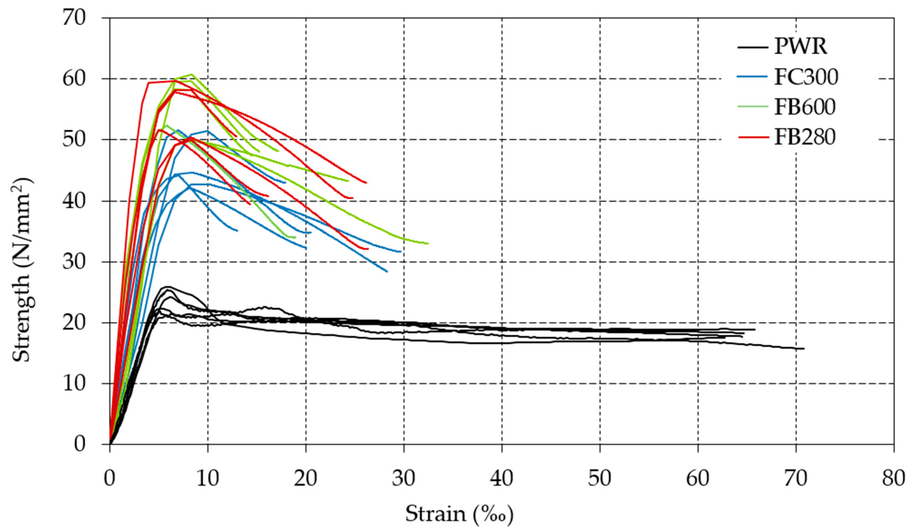
Figure 3 shows all of the strength–strain graphs obtained in the tests.
The results obtained in the compression tests (Table 2 and Figure 3) show that all of the reinforced pieces share very similar behavior. Furthermore, there are highly significant differences between the reinforced and unreinforced pieces, both in terms of the shape of the graphs and the values attained.

3.2.1. Unreinforced Pieces

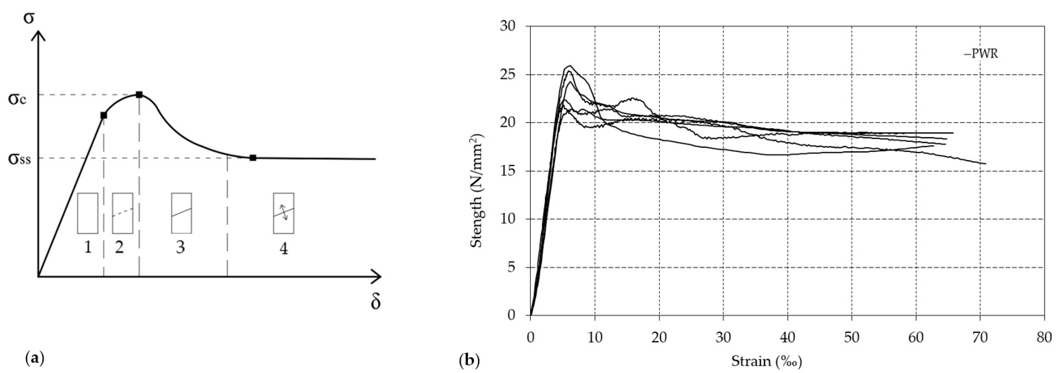
Figure 4a shows an idealized strength–strain graph of sawn wood elements subjected to compression testing [70,71,72]. In this graph, four phases can be clearly differentiated between the start of testing and breakage. Phase (1) is associated with an elastic and linear phase in which the modulus of elasticity of all of the pieces is very similar. Phase (2) is associated with a non-linear phase triggered by the formation of an incipient cutting plane of the fiber until the maximum test strength is reached (σmax). In phase (3), the cutting plane of the fibers experiences a significant rapid drop in strength levels. In phase (4), the development of the cutting plane is now stable and the strength levels remain at the same value until breakage occurs.
Figure 4b shows the strength–strain graphs for the unreinforced pieces of wood subjected to compression testing. It can be concluded that all of the pieces tested demonstrate very similar behavior and perfectly reflect the idealized graph of Figure 4a. The two specimens classified as Rejects in the visual classification, due to drying cracks, show no significant variation compared to those classified as C-22, which indicates that the drying cracks do not represent a defect that determines the behavior of the wood on compression [73].
Usually, the term ductility refers to the ability of a material to undergo plastic deformation before breaking. For all materials in general, and for wood in particular, there is no single definition for this term [74,75]. However, all of the technical and scientific literature is in agreement with regard to the beneficial effects of ductility on structures. Basically, all of the definitions of ductility can be grouped as one of two types—those based on the strains achieved up to breaking point and those based on strain energy densities [76]. Both of these types of ductility measurements have been used in this study, using for this purpose the values associated with breakage and the maximum load. Almost identical results were obtained for both procedures, very close to 12, which indicates the extraordinary ductility of these pieces when they are subjected to compression testing.

3.2.2. Reinforced Pieces

The strength–strain graphs for the reinforced pieces (Figure 3) show a very similar type of behavior for the three reinforcement types used—following an initial linear phase, the graph loses its linearity and reaches the maximum load after which the strength reduces in value until a strain is reached that provokes the breakage. However, there are significant variations in the value of the mechanical properties inferred in the graphs (Table 2). The value of the maximum strength reached is very similar with both basalt reinforcements and significantly higher, by between 18% and 20%, than the maximum strength of the test pieces reinforced with carbon fiber. The strain reached for the maximum strength value is also very similar in both basalt fabrics and lower, by between 25% and 29%, than that reached with carbon fiber reinforcements. The modulus of elasticity of the test pieces reinforced with carbon fiber is higher by between 8% and 15% than that for the test pieces reinforced with basalt fibers. For the ultimate strain values, it can be concluded that higher values are achieved in the test pieces featuring basalt fibers, by between 9% and 28%, than those containing carbon fibers.
Figure 5 shows a representation of the maximum strengths reached with the three types of reinforcement (Table 2) compared to the maximum force per unit of length that each type of reinforcement can offer (Table 1).
It can be concluded that even though fabrics FC300 and FB600 have practically the same mechanical capacity, they result in very different breaking strengths in the reinforced elements. Consequently, it may be said that there is no relationship between the mechanical capacity of the reinforcement and the ultimate strength of the test piece tested. This conclusion is also reached when wooden elements undergoing an accelerated aging process are reinforced with fiberglass fabrics [65].
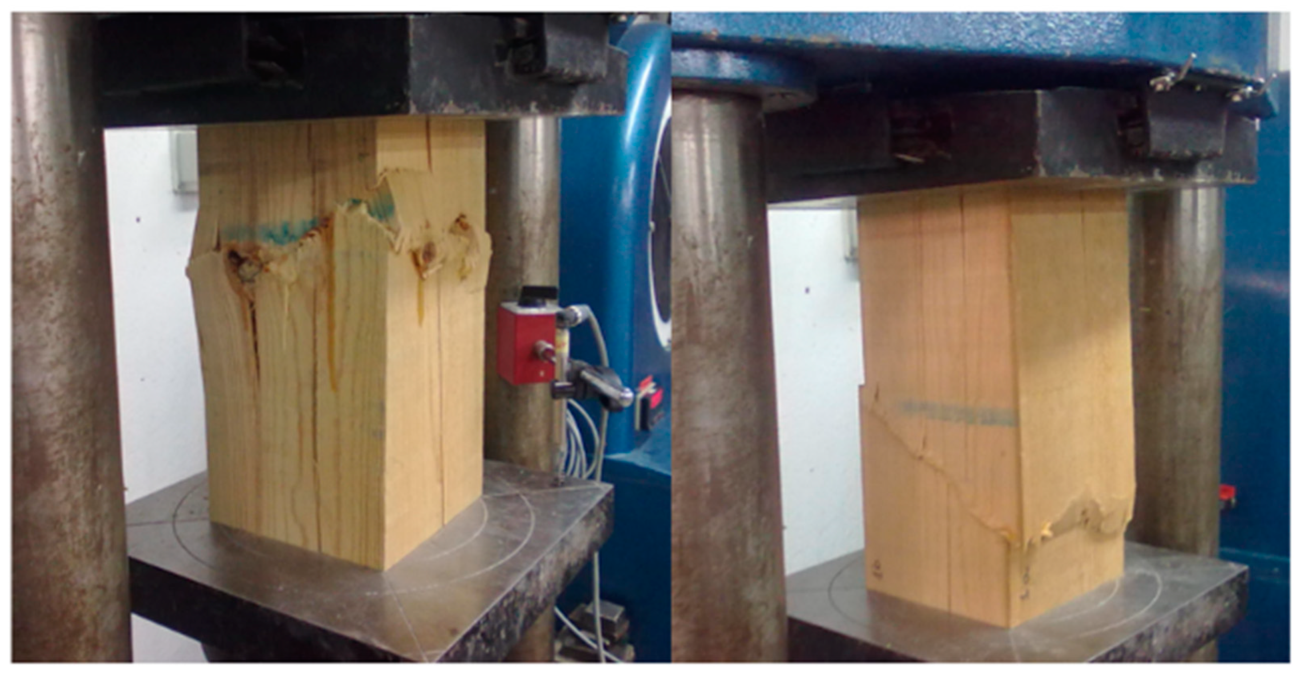
Reinforcement results in the lateral confinement of the wood fibers, preventing their displacement in a transverse direction. When a slip plane occurs in the wood, as in Figure 4a, the fabric comes apart, causing the piece to collapse. As such, the ultimate load of the piece is influenced more by local defects, such as knots in the wood, which cause it to break, than by the mechanical capacity of the reinforcement fabric. Figure 6 shows the breakage of the pieces of wood reinforced with each type of fabric and the slip plane created in the wood.
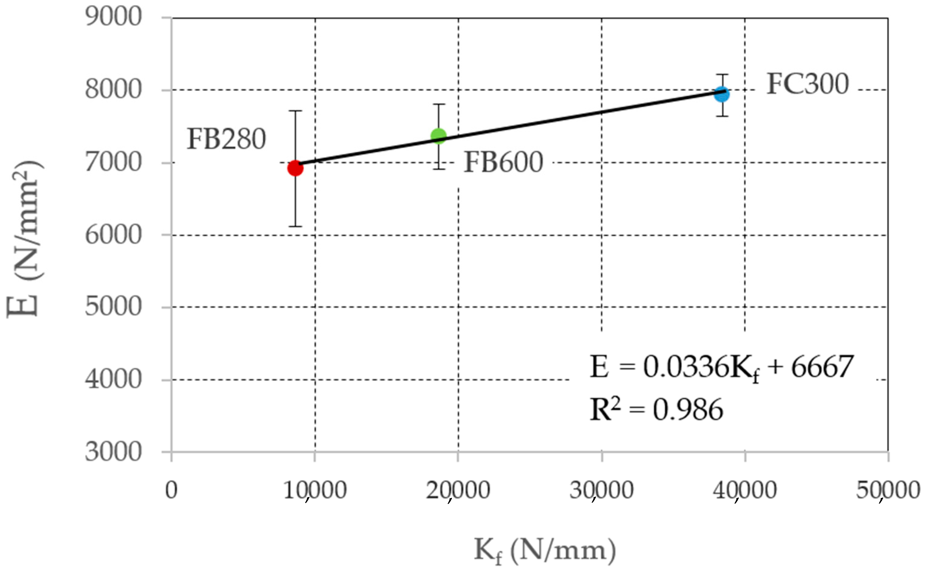
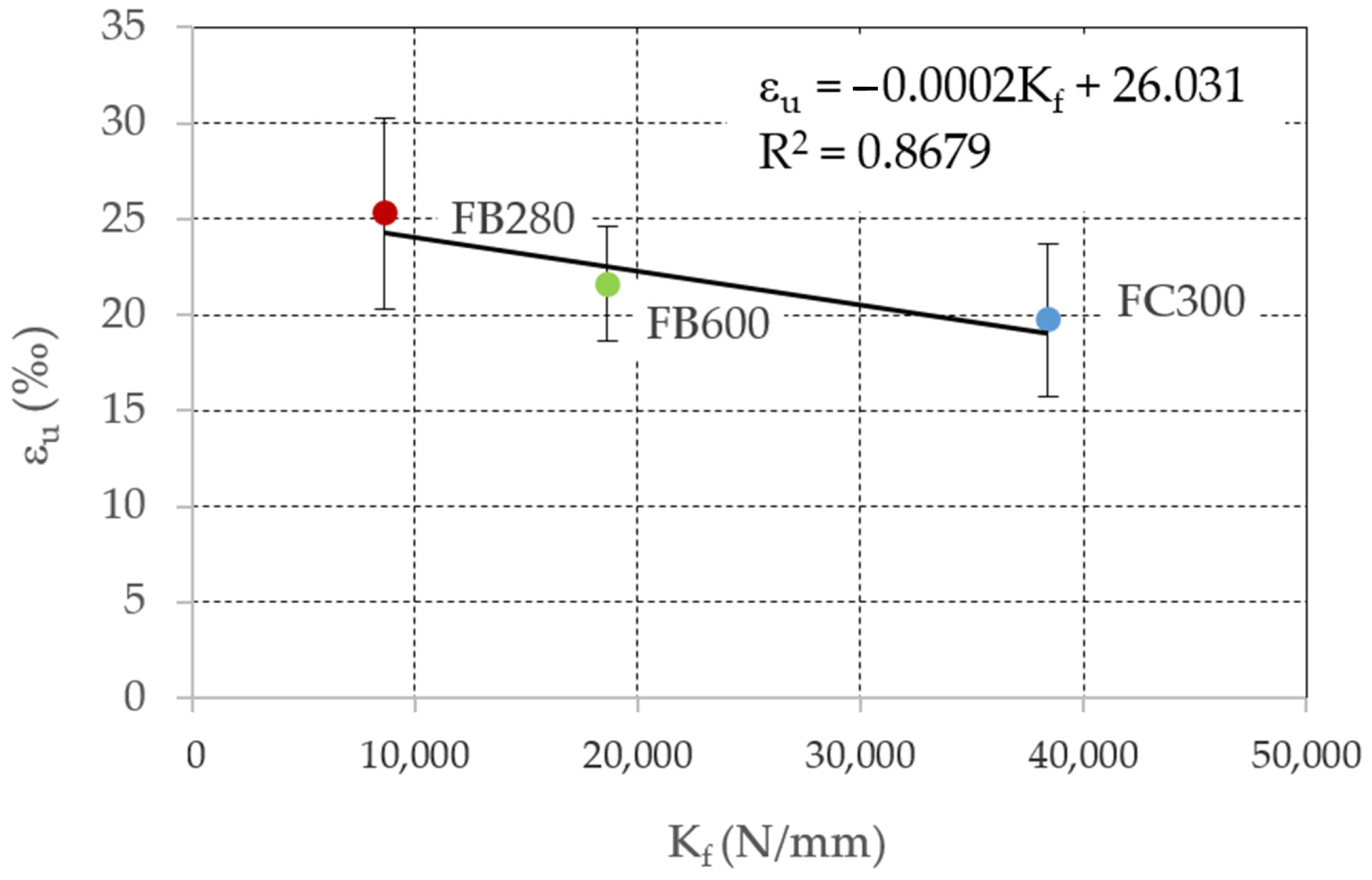
Figure 7 and Figure 8 show that there is a strong relationship between the rigidity of the reinforcement and the modulus of elasticity and the ultimate strain of the reinforced test piece.
The more rigid the reinforcement, the less transversal strain the section of the test piece will allow; this also translates into fewer longitudinal deformations and an increased modulus of elasticity. A virtually linear relationship was obtained (Figure 7) between the modulus of elasticity of the test piece and the rigidity of the reinforcement (R2 = 0.986).
The greater ultimate strains obtained with the FB280 reinforcements mean that, when ductility is measured as a function of the strains, the ductility obtained with this kind of reinforcement is somewhat higher than that for the other types.
Greater reinforcement rigidity means that when the test piece reaches the maximum test load due to fiber slippage, the greater rigidity of the rest of the test piece that has not broken prevents the deformation of the whole. As such, the deformation is concentrated in the area of the breakage with the resulting decrease in the value of the ultimate strain of the test piece. A good linear relationship was obtained (Figure 8) between the ultimate strain and the reinforcement rigidity (R2 = 0.868).
When ductility is measured as a function of the ultimate strain, the higher ultimate strain values obtained with the FB280 reinforcement mean that the ductility of the pieces reinforced with this kind of fabric is somewhat higher than the others (Table 2). When ductility is measured in terms of strain energy, more variables are involved and the results attained by the three kinds of reinforcement are very similar.
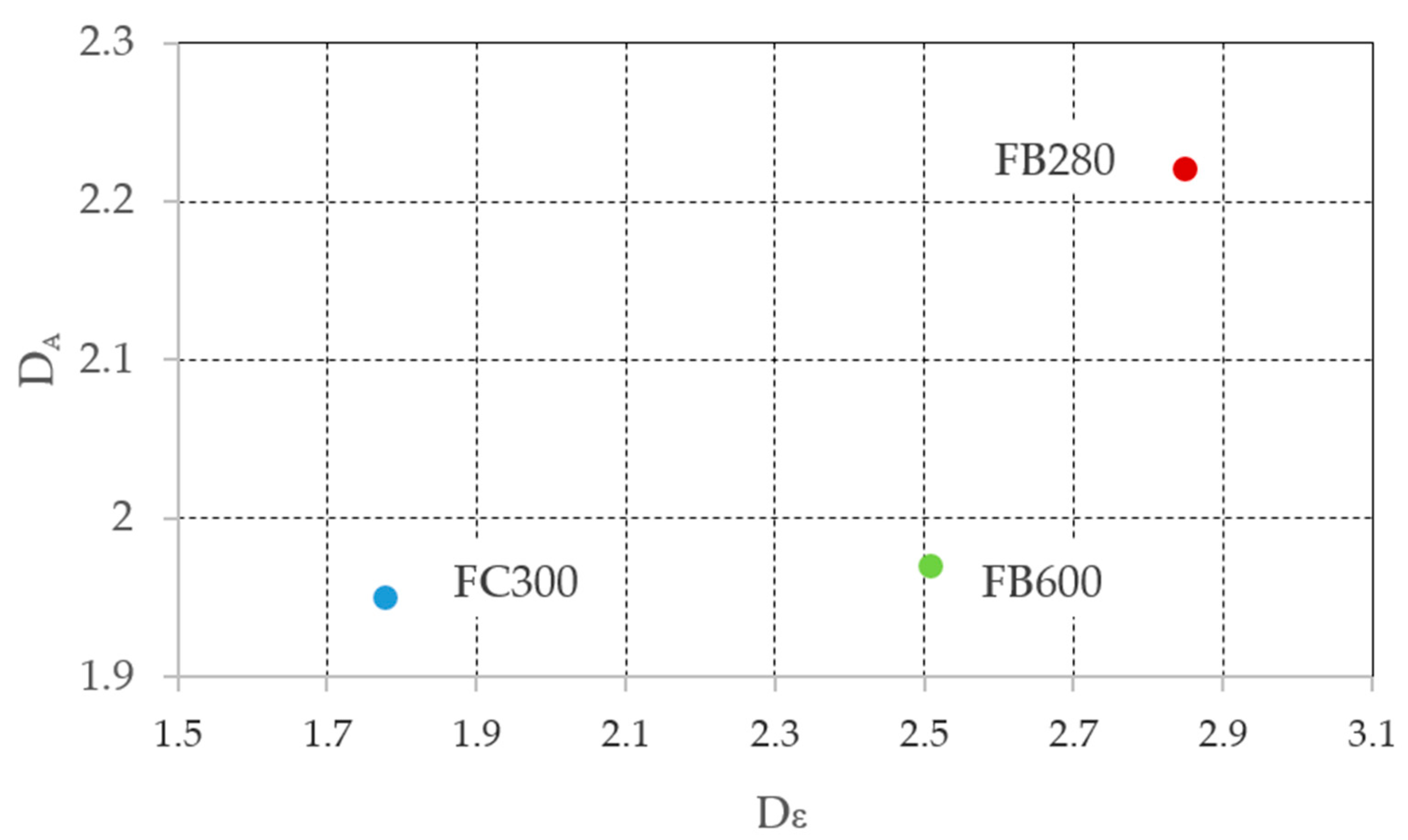
Figure 9 shows the relationship between the ductility measured using both types of procedures for the three reinforcement types.
On analysis of Figure 9, it appears that there is not a good relationship between the ductilities measured using the two procedures mentioned above. While it is true that the ductility of the FB280 reinforcement is always greater than that of the FB600 reinforcement, and the ductility of the latter is greater than that of the FC300 reinforcement, in the case of the ductilities measured in terms of strain energy, the differences are considerable between the three types of reinforcement. However, in the case of the ductility measured in terms of strain energy density, the values obtained for FC300 and FB600 are very similar and are far from those reached by FB280. As such, it may be said that it is not equivalent to measure the ductility of this kind of reinforcements using both procedures and a choice should be made to use the most appropriate procedure depending on the analysis that is to be carried out.

3.2.3. Comparison between Reinforced and Unreinforced Pieces

Based on the analysis of Figure 3, it is possible to deduce the different behavior of reinforced and unreinforced pieces. The shape of the strength–strain graphs is dramatically different. In reinforced pieces, the four phases of strength–strain behavior that we see in unreinforced pieces do not occur (Figure 4). Once the maximum test load is reached, a decrease in the strength values occurs until breakage, which takes place with ultimate strain values that are much lower than for unreinforced pieces.
FRP reinforcement results in the lateral confinement of the wood fibers, preventing their transversal displacement. At the moment when the reinforcement fabric breaks, due to being fragile when placed under stress, the piece may experience lateral deformation, such that the resilience of the lignin and hemicellulose in the wood is exceeded, resulting in the rapid and explosive breakage of the piece of wood due to the separation of the fibers. This behavior explains why, once the maximum test load has been reached, the subsequent phase of the strength–strain graph is shorter, breakage occurring more suddenly and dramatically.
There is a significant increase in the load capacity of the reinforced pieces compared to the unreinforced pieces. The reinforced pieces attain at least 96% greater resistance than the unreinforced pieces (FC300), reaching as much as 133% more resistance in the case of the pieces reinforced with FB600. The application of the reinforcement also resulted in an increased modulus of elasticity in the pieces and an increase in the strain occurring at the point of maximum strength (Table 2). However, the confinement of the pieces caused a highly significant decrease in the ultimate strain values, which also meant that the ductility of the reinforced pieces was much lower than that of the unreinforced pieces, by approximately a quarter or a sixth.

4. Conclusions

A total of 24 prismatic wild pinewood pieces were tested to compression until breaking point. Of those, 18 pieces were confined with three different FRP fabrics, while the rest were tested non-confined, as a benchmark. The following conclusions may be drawn from the results obtained:
  • The appearance of the strength–strain graph for all of the reinforced pieces is very similar, despite the huge difference between the three types of reinforcement;
  • There are highly significant differences between the reinforced and unreinforced pieces, both in terms of the shape of the graphs and the values attained;
  • All of the reinforced pieces exhibit a significant decrease in breaking strain, compared to the unreinforced pieces. Although the modulus of elasticity and the maximum strengths increases, the density of deformation energy of the reinforced pieces decreases;
  • There is no relationship between the mechanical capacity of the reinforcement and the ultimate strength of the test piece tested;
  • There is a strong relationship between the rigidity of the reinforcement and modulus of elasticity and the ultimate strain of the reinforced test piece. The greater the rigidity of the reinforcement, the greater the modulus of elasticity and the lower the ultimate strain;
  • There is not a strong relationship between the ductilities measured using terms of deformation and strain energy density;
  • As a final conclusion, it can be indicated that the three types of reinforcement have very similar strength–strain diagrams in the pieces tested, with important increases in maximum strength and a very significant decrease in ultimate strain. This means that in projects of wooden structures reinforced by these procedures, it is necessary to take into account the decrease in ductility that occurs in the reinforced elements.

Author Contributions

Conceptualization, P.d.l.R. and E.G.; methodology, M.d.l.N.G.; software, M.I.P.; validation, P.d.l.R. and M.d.l.N.G.; formal analysis, M.I.P.; investigation, E.G.; resources, E.G.; data curation, M.I.P.; writing—original draft preparation, P.d.l.R.; writing—review and editing, M.d.l.N.G.; visualization, E.G.; supervision, M.d.l.N.G. and P.d.l.R.; project administration, M.I.P.; funding acquisition, E.G. All authors have read and agreed to the published version of the manuscript.

Funding

This research received no external funding.

Institutional Review Board Statement

We exclude this statement because the study did not involve humans or animals.

Informed Consent Statement

We exclude this statement because the study did not involve humans.

Data Availability Statement

The raw data required to reproduce these findings cannot be shared at this time as the data also form part of an ongoing study. The processed data required to reproduce these findings cannot be shared at this time as the data also form part of an ongoing study.

Acknowledgments

The authors thank the School of Building Engineering of the Universidad Politécnica de Madrid. In addition, the support of Drizoro Construction Products, S.A.U. is gratefully acknowledged.

Conflicts of Interest

The authors declare no conflict of interest.

References

  1. Walberg, D. Solid and timber construction in residential buildings/Massiv-und Holzbau bei Wohngebäuden. Mauerwerk 2016, 20, 16–31. [Google Scholar] [CrossRef]
  2. Conners, T.E. Segmented models for stress-strain diagrams. Wood Sci. Technol. 1989, 23, 65–73. [Google Scholar] [CrossRef]
  3. Handbook, W. Edition Wood Handbook-Wood as an Engineering Material; General Technical Report FPL-GTR-190; US Department of Agriculture, Forest Service, Forest Products Laboratory: Madison, WI, USA, 2010. [Google Scholar]
  4. Cabrero, J.M.; Heiduschke, A.; Haller, P. Analytical assessment of the load-carrying capacity of axially loaded wooden reinforced tubes. Compos. Struct. 2010, 92, 2955–2965. [Google Scholar] [CrossRef] [Green Version]
  5. Buchanan, A.H. Bending Strength of Lumber. J. Struct. Eng. 1990, 116, 1213–1229. [Google Scholar] [CrossRef]
  6. Benabou, L. Predictions of compressive strength and kink band orientation for wood species. Mech. Mater. 2010, 42, 335–343. [Google Scholar] [CrossRef]
  7. Zhang, W.; Song, X.; Gu, X.; Tang, H. Compressive Behavior of Longitudinally Cracked Timber Columns Retrofitted Using FRP Sheets. J. Struct. Eng. 2012, 138, 90–98. [Google Scholar] [CrossRef]
  8. Custódio, J.; Broughton, J.; Cruz, H. A review of factors influencing the durability of structural bonded timber joints. Int. J. Adhes. Adhes. 2009, 29, 173–185. [Google Scholar] [CrossRef]
  9. Beckmann, P.; Bowles, R. Structural Aspects of Building Conservation; Routledge: London, UK, 2012. [Google Scholar] [CrossRef]
  10. Li, Y.-F.; Xie, Y.-M.; Tsai, M.-J. Enhancement of the flexural performance of retrofitted wood beams using CFRP composite sheets. Constr. Build. Mater. 2009, 23, 411–422. [Google Scholar] [CrossRef]
  11. Dehn, F.; Gebhardt, M.; Pollnow, E. Rehabilitation and strengthening of foundation components. Bautechnik 2008, 85, 120–132. [Google Scholar] [CrossRef]
  12. Johns, K.C.; Lacroix, S. Composite reinforcement of timber in bending. Can. J. Civ. Eng. 2000, 27, 899–906. [Google Scholar] [CrossRef]
  13. Plevris, N.; Triantafillou, T.C. FRP-Reinforced Wood as Structural Material. J. Mater. Civ. Eng. 1992, 4, 300–317. [Google Scholar] [CrossRef]
  14. Triantafillou, T.C.; Deskovic, N. Prestressed FRP Sheets as External Reinforcement of Wood Members. J. Struct. Eng. 1992, 118, 1270–1284. [Google Scholar] [CrossRef]
  15. Bank, L.C. Composites for Construction: Structural Design with FRP Materials; Wiley: Hoboken, NJ, USA, 2006; ISBN 978-0-471-68126-7. [Google Scholar]
  16. Machida, A. State-of-the-art report on continuous fiber reinforcing materials. In Second Research Committee on CFRM, Japan Society of Civil Engineers: Concrete Engineering Series; Japan Society of Civil Engineers: Tokyo, Japan, 1993. [Google Scholar]
  17. Pendhari, S.S.; Kant, T.; Desai, Y.M. Application of polymer composites in civil construction: A general review. Compos. Struct. 2008, 84, 114–124. [Google Scholar] [CrossRef]
  18. Neale, K.W. Advanced Composite Materials in Bridges and Structures: 1st International Conference, Sheerbrooke, Québec, Canada, 1992; Canadian Society for Civil Engineering: Montreal, QC, Canada, 1992. [Google Scholar]
  19. Nanni, A.; Di Tommaso, A.; Cheng, J.; Arduini, M. International Research on Advanced Composites in Construction (IRACC-96); Final Report to US National Science Foundation; National Science Foundation: Alexandria, VA, USA, 1996.
  20. Lopresto, V.; Leone, C.; De Iorio, I. Mechanical characterisation of basalt fibre reinforced plastic. Compos. Part B Eng. 2011, 42, 717–723. [Google Scholar] [CrossRef]
  21. Wang, X.; Wu, Z.; Wu, G.; Zhu, H.; Zen, F. Enhancement of basalt FRP by hybridization for long-span cable-stayed bridge. Compos. Part B Eng. 2013, 44, 184–192. [Google Scholar] [CrossRef]
  22. Larrinaga, P.; Chastre, C.; Biscaia, H.C.; San-José, J.T. Experimental and numerical modeling of basalt textile reinforced mortar behavior under uniaxial tensile stress. Mater. Des. 2014, 55, 66–74. [Google Scholar] [CrossRef]
  23. Alam, P.; Ansell, M.P.; Smedley, D. Mechanical repair of timber beams fractured in flexure using bonded-in reinforcements. Compos. Part B Eng. 2009, 40, 95–106. [Google Scholar] [CrossRef]
  24. Ogawa, H. Architectural application of carbon fibers. Carbon 2000, 38, 211–226. [Google Scholar] [CrossRef]
  25. Ahmad, S.; Shah, A.; Nawaz, A.; Salimullah, K. Refuerzo a cortante de ménsulas con polímeros reforzados con fibra de car-bono (CFRP). Mater. Constr. 2010, 299, 79–97. [Google Scholar] [CrossRef] [Green Version]
  26. Parra, C.; Martínez-Conesa, E.; Valcuende, M.; Garrido, A. Análisis de métodos para evaluar el refuerzo a esfuerzo cortante con CFRP en vigas de hormigón armado. Inf. Constr. 2012, 64, 197–206. [Google Scholar] [CrossRef] [Green Version]
  27. Subagia, I.A.; Kim, Y.; Tijing, L.D.; Kim, C.S.; Shon, H.K. Effect of stacking sequence on the flexural properties of hybrid composites reinforced with carbon and basalt fibers. Compos. Part B Eng. 2014, 58, 251–258. [Google Scholar] [CrossRef]
  28. Karbhari, V.M.; Chin, J.W.; Hunston, D.; Benmokrane, B.; Juska, T.; Morgan, R.; Lesko, J.J.; Sorathia, U.; Reynaud, D. Durability Gap Analysis for Fiber-Reinforced Polymer Composites in Civil Infrastructure. J. Compos. Constr. 2003, 7, 238–247. [Google Scholar] [CrossRef] [Green Version]
  29. Zhou, J.; Lucas, J.P. Hygrothermal effects of epoxy resin. Part II: Variations of glass transition temperature. Polymers 1999, 40, 5513–5522. [Google Scholar] [CrossRef]
  30. DT202, C. Guidelines for the Design and Construction of Externally Bonded FRP Systems for Strengthening Existing Structures; National Research Council, Advisory Committee on Technical Regulations for Constructions: Rome, Italy, 2005. [Google Scholar]
  31. FIB. FRP reinforcement in RC structures. In Desing and Use of Fibre Reinforced Polymer Reinforcement (FRP) in Reinforced Con-Crete Structures; FIB bulletin Nº. 40 September 2007; International Federation for Structural Concrete: Lausanne, Switzerland, 2007; ISBN 978-2-88394-080-2. [Google Scholar]
  32. Li, Y.-F.; Tsai, M.-J.; Wei, T.-F.; Wang, W.-C. A study on wood beams strengthened by FRP composite materials. Constr. Build. Mater. 2014, 62, 118–125. [Google Scholar] [CrossRef]
  33. Rescalvo, F.J.; Valverde-Palacios, I.; Suarez, E.; Gallego, A. Experimental and analytical analysis for bending load capacity of old timber beams with defects when reinforced with carbon fiber strips. Compos. Struct. 2018, 186, 29–38. [Google Scholar] [CrossRef]
  34. Gómez, E.; Cobo, A.; González, M. Reinforcement and repair of small sawn Pinus Sylvestris beams with carbon fiber. Compos. Part B Eng. 2016, 101, 147–154. [Google Scholar] [CrossRef] [Green Version]
  35. de la Rosa, P.; Cobo, A.; González, M. Analysis of the flexural stiffness of timber beams reinforced with carbon and basalt composite materials. Compos. Part B Eng. 2016, 86, 152–159. [Google Scholar] [CrossRef]
  36. de la Rosa, P.; Cobo, A.; González, M. Bending reinforcement of timber beams with composite carbon fiber and basalt fiber materials. Compos. Part B Eng. 2013, 55, 528–536. [Google Scholar] [CrossRef] [Green Version]
  37. Gómez, E.; González, M.; Hosokawa, K.; Cobo, A. Experimental study of the flexural behavior of timber beams reinforced with different kinds of FRP and metallic fibers. Compos. Struct. 2019, 213, 308–316. [Google Scholar] [CrossRef]
  38. Turgay, T.; Polat, Z.; Koksal, H.; Doran, B.; Karakoç, C. Compressive behavior of large-scale square reinforced concrete columns confined with carbon fiber reinforced polymer jackets. Mater. Des. 2010, 31, 357–364. [Google Scholar] [CrossRef]
  39. Feng, P.; Cheng, S.; Bai, Y.; Ye, L. Mechanical behavior of concrete-filled square steel tube with FRP-confined concrete core subjected to axial compression. Compos. Struct. 2015, 123, 312–324. [Google Scholar] [CrossRef]
  40. Toutanji, H. Stress-Strain Characteristics of Concrete Columns Externally Confined with Advanced Fiber Composite Sheets. ACI Mater. J. 1999, 96, 397–404. [Google Scholar] [CrossRef]
  41. Nanni, A.; Norris, M.; Bradford, N. Lateral confinement of concrete using FRP reinforcement. Spec. Publ. 1993, 138, 193–210. [Google Scholar]
  42. Hooton, R.; Larralde, J. Compressive Strength of Small Concrete Specimens Confined with Fiberglass Laminates. Cem. Concr. Aggreg. 1997, 19, 17. [Google Scholar] [CrossRef]
  43. Saafi, M.; Toutanji, H.; Li, Z. Behavior of Concrete Columns Confined with Fiber Reinforced Polymer Tubes. ACI Mater. J. 1999, 96, 500–509. [Google Scholar] [CrossRef]
  44. Csuka, B.; Kollár, L.P. Analysis of FRP confined columns under eccentric loading. Compos. Struct. 2012, 94, 1106–1116. [Google Scholar] [CrossRef] [Green Version]
  45. Aire, C.; Gettu, R.; Casas, J.R.; Marques, S.; Marqués, D. Estudio experimental y modelo teórico del hormigón confinado lateralmente con polímeros reforzados con fibras (FRP). Mater. Constr. 2010, 60, 19–31. [Google Scholar] [CrossRef] [Green Version]
  46. De Diego, A.; Arteaga, A.; Fernández, J.; Perera, R.; Cisneros, D. Behaviour of FRP confined concrete in square columns. Mater. Constr. 2015, 65, 069. [Google Scholar] [CrossRef] [Green Version]
  47. El Maaddawy, T. Strengthening of Eccentrically Loaded Reinforced Concrete Columns with Fiber-Reinforced Polymer Wrapping System: Experimental Investigation and Analytical Modeling. J. Compos. Constr. 2009, 13, 13–24. [Google Scholar] [CrossRef]
  48. Daugevičius, M.; Valivonis, J.; Beinaravičius, A.; Skuturna, T.; Budvytis, M. Experimental Investigation of the Load Carrying Capacity of Eccentrically Loaded Reinforced Concrete Elements Strengthened with CFRP. Procedia Eng. 2013, 57, 232–237. [Google Scholar] [CrossRef] [Green Version]
  49. Harmon, T.G.; Ramakrishnan, S.; Wang, E.H. Confined Concrete Subjected to Uniaxial Monotonic Loading. J. Eng. Mech. 1998, 124, 1303–1309. [Google Scholar] [CrossRef]
  50. Li, Q.; Ansari, F. High-Strength Concrete in Triaxial Compression by Different Sizes of Specimens. ACI Mater. J. 2000, 97, 684–689. [Google Scholar] [CrossRef]
  51. Xie, J.; Elwi, A.; MacGregor, J. Mechanical Properties of Three High-Strength Concretes Containing Silica Fume. ACI Mater. J. 1995, 92, 135–145. [Google Scholar] [CrossRef]
  52. Almusallam, T.H. Behavior of normal and high-strength concrete cylinders confined with E-glass/epoxy composite laminates. Compos. Part B Eng. 2007, 38, 629–639. [Google Scholar] [CrossRef]
  53. Micelli, F.; Modarelli, R. Experimental and analytical study on properties affecting the behaviour of FRP-confined concrete. Compos. Part B Eng. 2013, 45, 1420–1431. [Google Scholar] [CrossRef]
  54. Vincent, T.; Ozbakkaloglu, T. Influence of concrete strength and confinement method on axial compressive behavior of FRP confined high- and ultra high-strength concrete. Compos. Part B Eng. 2013, 50, 413–428. [Google Scholar] [CrossRef] [Green Version]
  55. Lam, L.; Teng, J. Stress–strain model for FRP-confined concrete under cyclic axial compression. Eng. Struct. 2009, 31, 308–321. [Google Scholar] [CrossRef]
  56. Abbasnia, R.; Ziaadiny, H. Behavior of concrete prisms confined with FRP composites under axial cyclic compression. Eng. Struct. 2010, 32, 648–655. [Google Scholar] [CrossRef]
  57. Abbasnia, R.; Hosseinpour, F.; Rostamian, M.; Ziaadiny, H. Cyclic and monotonic behavior of FRP confined concrete rectangular prisms with different aspect ratios. Constr. Build. Mater. 2013, 40, 118–125. [Google Scholar] [CrossRef]
  58. Faustino, P.; Frade, P.; Chastre, C. Lateral Cyclic Behaviour of RC Columns Confined With Carbon Fibres. Structures 2016, 5, 196–206. [Google Scholar] [CrossRef]
  59. Bouchelaghem, H.; Bezazi, A.; Scarpa, F. Compressive behaviour of concrete cylindrical FRP-confined columns subjected to a new sequential loading technique. Compos. Part B Eng. 2011, 42, 1987–1993. [Google Scholar] [CrossRef]
  60. Li, P.; Wu, Y.-F. Stress–strain model of FRP confined concrete under cyclic loading. Compos. Struct. 2015, 134, 60–71. [Google Scholar] [CrossRef]
  61. Fernández-Cánovas, M.; González-García, M.N.; Piñero, J.Á.; Cobo, A. Compressive strength behaviour of low- and medium-strength concrete specimens confined with carbon fibres in defective implementation conditions: An experimental study. Mater. Constr. 2016, 66, 103. [Google Scholar] [CrossRef] [Green Version]
  62. André, A.; Kliger, R.; Olsson, R. Compression failure mechanism in small-scale wood specimens reinforced with CFRP: An experimental study. Constr. Build. Mater. 2013, 41, 790–800. [Google Scholar] [CrossRef]
  63. Gezer, H.; Aydemir, B. The effect of the wrapped carbon fiber reinforced polymer material on fir and pine woods. Mater. Des. 2010, 31, 3564–3567. [Google Scholar] [CrossRef]
  64. Najm, H.; Secaras, J.; Balaguru, P. Compression Tests of Circular Timber Column Confined with Carbon Fibers Using Inorganic Matrix. J. Mater. Civ. Eng. 2007, 19, 198–204. [Google Scholar] [CrossRef]
  65. Kim, K.-H.E.; Andrawes, B. Compression behavior of FRP strengthened bridge timber piles subjected to accelerated aging. Constr. Build. Mater. 2016, 124, 177–185. [Google Scholar] [CrossRef]
  66. Wang, L.; Liu, W.; Hui, D. Compression strength of hollow sandwich columns with GFRP skins and a paulownia wood core. Compos. Part B Eng. 2014, 60, 495–506. [Google Scholar] [CrossRef]
  67. Asociación Española de Normalización. Visual Grading for Structural Sawn Timber. Coniferous Timber (UNE 56544). 2011. Available online: https://www.aenor.com/normas-y-libros/buscador-de-normas/une/?c=N0048310 (accessed on 14 December 2020).
  68. Asociación Española de Normalización. Structural Timber—Strength Classes—Assignment of Visual Grades and Species (UNE-EN 1912). 2012. Available online: https://www.une.org/encuentra-tu-norma/busca-tu-norma/norma?c=N0049485 (accessed on 10 December 2020).
  69. Asociación Española de Normalización. Structural Timber—Strength Classes (UNE-EN 338). 2016. Available online: https://www.aenor.com/normas-y-libros/buscador-de-normas/une/c=N0057443 (accessed on 7 January 2021).
  70. Argon, A. Fracture of Composites. Treatise Mater. Sci. Technol. 1972, 1, 79–114. [Google Scholar] [CrossRef]
  71. Budiansky, B. Micromechanics. Comput. Struct. 1983, 16, 3–12. [Google Scholar] [CrossRef]
  72. André, A.; Kliger, R.; Asp, L. Compression failure mechanism in small scale timber specimens. Constr. Build. Mater. 2014, 50, 130–139. [Google Scholar] [CrossRef]
  73. Esteban, M.; Arriaga, F.; Íñiguez, G.; Bobadilla, I.; Mateo, R.; Iñiguez-Gonzalez, G.; Maldonado, I.B. Influencia de las fendas en la resistencia de la madera estructural. Mater. Constr. 2010, 60, 115–132. [Google Scholar] [CrossRef] [Green Version]
  74. Stehn, L.; Björnfot, A. Comparison of different ductility measures for a nailed steel-to-timber connection. In Proceedings of the World Conference on Timber Engineering, Shah Alam, Malaysia, 12–15 August 2002; Volume 2, pp. 155–162. [Google Scholar]
  75. Jorissen, A.; Fragiacomo, M. General notes on ductility in timber structures. Eng. Struct. 2011, 33, 2987–2997. [Google Scholar] [CrossRef]
  76. Malo, K.; Siem, J.; Ellingsbø, P. Quantifying ductility in timber structures. Eng. Struct. 2011, 33, 2998–3006. [Google Scholar] [CrossRef]
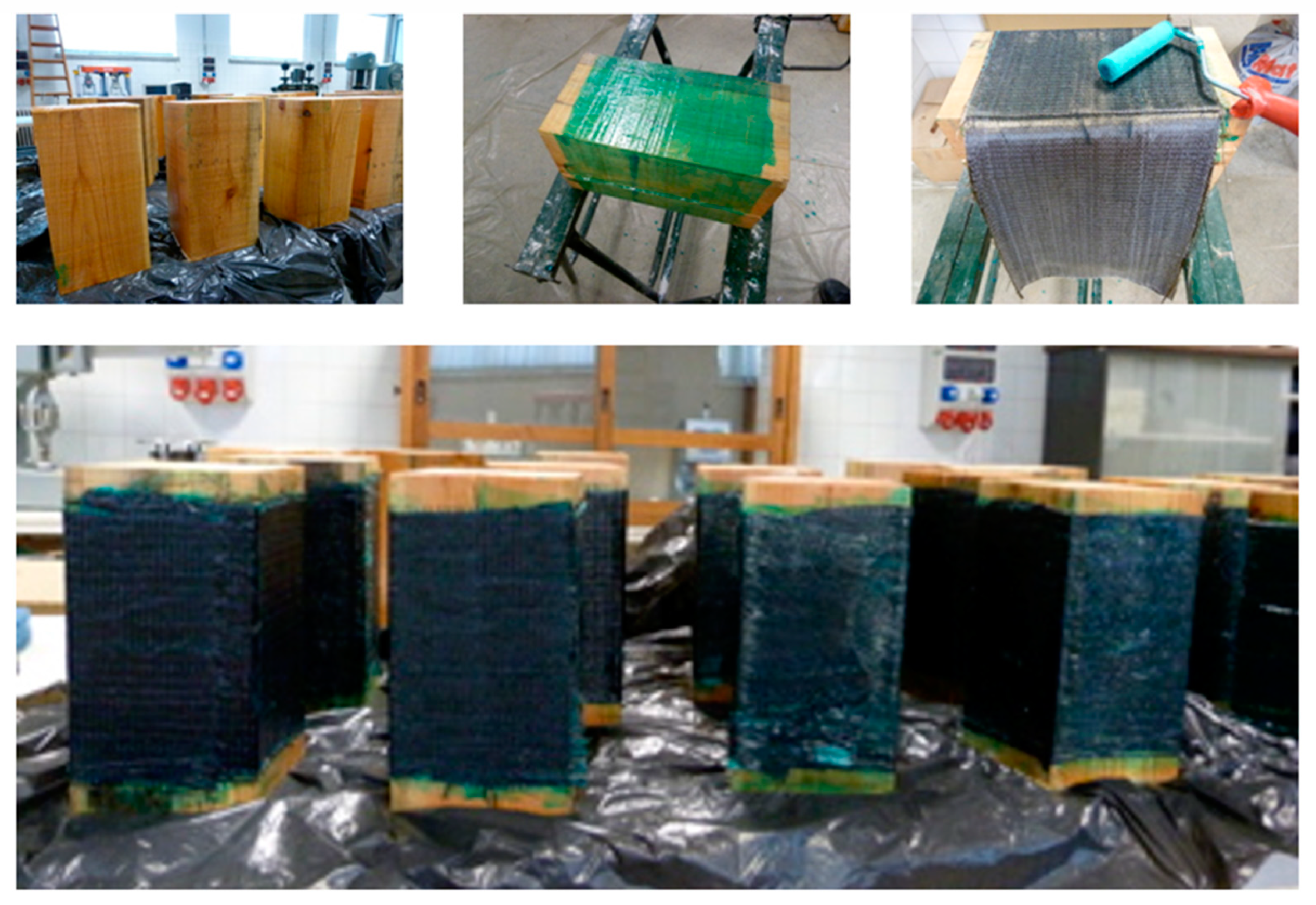
Figure 1. Process of reinforcing wooden pieces with carbon and basalt fibers.
Applsci 11 02460 g001
Figure 2. Image of the compression testing of an unreinforced piece of wood.
Applsci 11 02460 g002
Figure 3. Strength–strain graphs for all of the pieces subjected to compression testing.
Applsci 11 02460 g003
Figure 4. Strength–strain graphs for pieces of wood subjected to compression testing. (a) Idealized graph, (b) Real graphs.
Applsci 11 02460 g004
Figure 5. Relationship between the maximum strengths reached and the mechanical capacity of the reinforcements.
Applsci 11 02460 g005
Figure 6. Breakage of reinforced pieces. (a) FC300, (b) FB280, and (c) FB600.
Applsci 11 02460 g006
Figure 7. Relationship between the modulus of elasticity of the reinforced test pieces and the rigidity of the reinforcements.
Applsci 11 02460 g007
Figure 8. Relationship between the ultimate strain of the reinforced test pieces and the rigidity of the reinforcements.
Applsci 11 02460 g008
Figure 9. Relationship between the ductility measured by strain and by strain energy density for the three reinforcement types.
Applsci 11 02460 g009
Table 1. Geometrical and mechanical characteristics of the fabrics used.
G (g/m2)t (mm)σf (N/mm2)Ef (GPa)Ff (N/mm)Kf (N/mm)
FC3003000.167490023081838,410
FB2802800.1034000844128652
FB6006000.22240008488818,648
Table 2. Average density and results obtained in compression tests up to breaking point.
σmax *
(N/mm2)
E (N/mm2)εmax *
(‰)
εu *
(‰)
WR23.70/1.5255325.84/0.3467.25/2.78
FC30046.14/3.89793411.11/0.7219.74/3.95
FB28054.64/4.0069128.88/0.7825.30/4.95
FB60055.16/4.4973628.61/0.1521.62/3.37
Ae
(N/mm2)
Au
(N/mm2)
DεDAρ
(kg/m3)
WR92.041115.6011.5112.12554.31
FC300307.32599.831.781.95527.68
FB280276.35612.592.852.22513.19
FB600310.57611.902.511.97534.27
* Average value/Standard deviation.
Publisher’s Note: MDPI stays neutral with regard to jurisdictional claims in published maps and institutional affiliations.