1. Introduction
Augmented reality (AR) is a technology that can accurately and reproducibly superimpose to the real-world environment. An AR system fulfills 3 features: A combination of real and virtual objects, real-time interaction, and accurate 3 dimensions of space registration of virtual and real objects. The first AR device was developed by Ivan Sutherland in 1968. He set up a head-mounted 3-dimensional display, and the observer could see a cube in the view [
1].
The development of AR is attributed to Boeing in 1990. Before AR technology, Boeing’s workers were required to continuously discuss a laptop screen to ensure that the numerous wires were correctly connected. The process was exhausting and time consuming. Boeing’s engineers developed AR headsets, which helped the workers see the information projected in front of their eyes, which improved their wire construction efficiency and lowered errors [
2,
3]. Gradually, AR expanded to various fields, including gaming, service, factory assembly, and medical industries. In the field of oral medicine, AR is also used in oral maxillofacial surgeries, dental implant [
4,
5], and oral education [
6]. In addition, AR can promote the development of orthodontics [
3].
The problem of accurate orthodontic bracket positioning is being discussed for many decades now. In 1972, Andrews devised the straight wire (preadjusted) appliance, which the technique reduces a part of wire bending [
7,
8,
9]. The concept of straight wire appliance is each bracket has built-in specific torque, tip, in/out, and proper offset to achieve proper alignment of the center of the slot and to allow teeth to properly settle in the ideal final positions. The most important thing when using the straight wire appliance is bracket positions.
However, inaccurate bracket positions can affect occlusal function and dental aesthetics, causing articulation disorders and grooved marginal ridges between teeth; inaccurate bracket positions can also increase the likelihood of food becoming lodged between teeth, which can inflame the gingiva, damage the alveolar bone, and lead to periodontal disease [
10]. The problem of inaccurate bracket positions does not only occur because of orthodontics being performed by different clinical dentists. Even when the treatment is performed by the same dentist, bracket deviation of teeth in different quadrants is likely. Various factors can affect bracket positioning, including the clinical crown height, tooth morphology, abnormal incisor line, and occlusal interference. Therefore, making accurate orthodontic decisions is critical for clinical dentists. In the past, dentists could only rely on their experience and adjust the bracket positions until correct positioning was achieved.
Following advances in information and communications technology, digital applications in dentistry have increased, including three-dimensional (3D) intraoral scanning, cone beam computed tomography, computer-aided design and manufacturing, and the production of surgical guides. Digital dentistry has increased the quality and accuracy of dental treatment. The technique of 3D intraoral scanning can digitalize the intraoral structure, facilitating treatment planning and simulation with the aid of 3D software.
To prevent inaccurate bracket positioning and help dentists make appropriate decisions, researchers have proposed the incorporation of customized orthodontics into digital orthodontics. Advances in digital orthodontics allow the use of 3D models in customizing brackets according to the patient’s malocclusion type and individual problems. Studies [
11,
12,
13] have focused on bracket positioning methods, including positioning methods using orthodontic surgical guides, positioning gauges, and 3D-printed guides [
11,
12,
13].
Despite the progress of digital orthodontic techniques in recent years, the use of advanced techniques (e.g., using 3D-printed guides) for bracket positioning can incur heavy costs and thus reduce the generalizability of digital orthodontics. To solve this problem, the present study proposed an AR-assisted bracket navigation system to shift preoperational planning to clinical practice, with the aim of reducing guide production time and cost, enhancing the accuracy of bracket bonding, and achieving customized orthodontics.
To facilitate the accurate localization of bracket positioning, we developed an AR-assisted bracket navigation system. This study analyzed the accuracy of bracket placement between the conventional direct bonding technique with Boone gauge and AR-assisted bracket navigation system by the novice and the expert (
Figure 1).
2. Materials and Methods
2.1. Samples and Operators
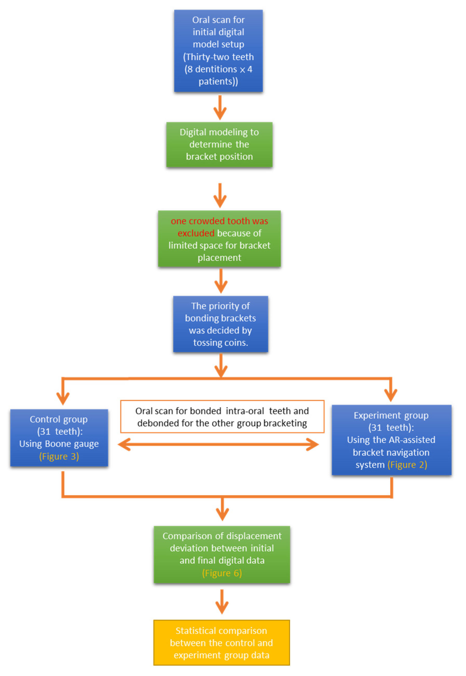
This clinical trial enrolled 4 patients (2 women and 2 men). All patients had intact central and lateral upper and lower incisors, and clinical crown heights of all teeth were available. Thirty-two teeth (8 dentitions × 4 patients) were examined. Incisors with the following conditions were excluded: (1) Limited space for bracket placement, (2) severe defects that could interfere with bracket placement, and (3) teeth with prosthesis that could hinder bracket bonding and tooth morphology. One crowded tooth was excluded because of limited space for bracket placement.
First, 31 brackets were bonded using either the AR-assisted bracket navigation system or Boone gauge and subjected to oral scan; then, the teeth were debonded and were rebonded with the other technique, and then were re-subjected to oral scan.
Bracket bonding was performed in each tooth by 2 operators: One was well trained in the orthodontic program for 3 years, and the other was an intern with only basic orthodontic knowledge and without any clinical orthodontic experience. The study was performed in the department of orthodontics, China Medical University Hospital Medical Center, Taichung, Taiwan. The study was approved by the local research ethics committee (CMUH106-REC3-146), and each participant signed an informed consent form.
2.2. AR and Device Settings
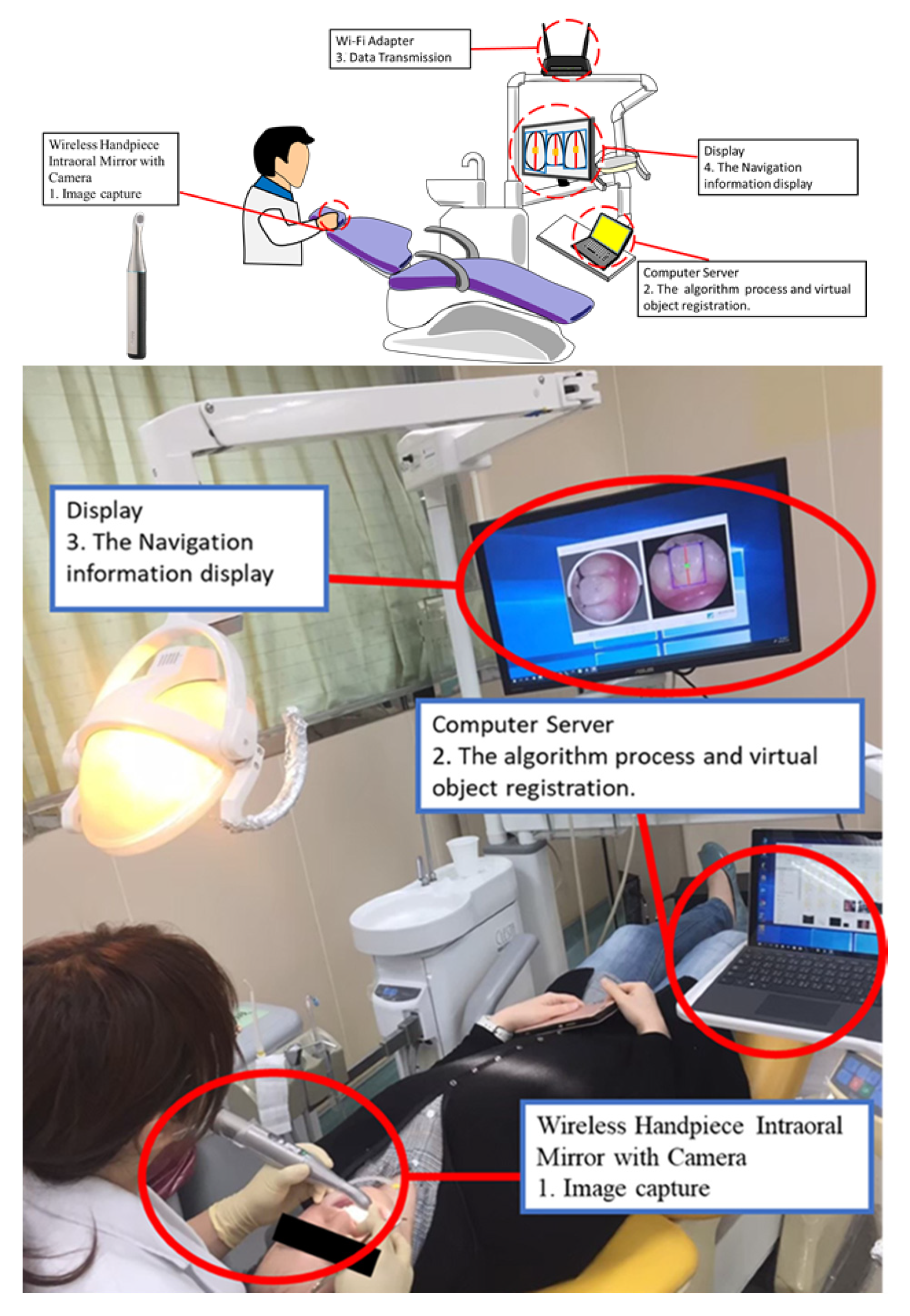
A wireless handpiece intra-oral camera (QOCA
® Q-tube Wi-Fi Teeth Scope Pro, Quanta Computer Inc., Taoyuan City, Taiwan) was used, with the resolution and operation distance set to 640 × 640 pixels and 3–12 mm, respectively. The operator can visualize the view of the patient’s mouth and augmented information from the screen (
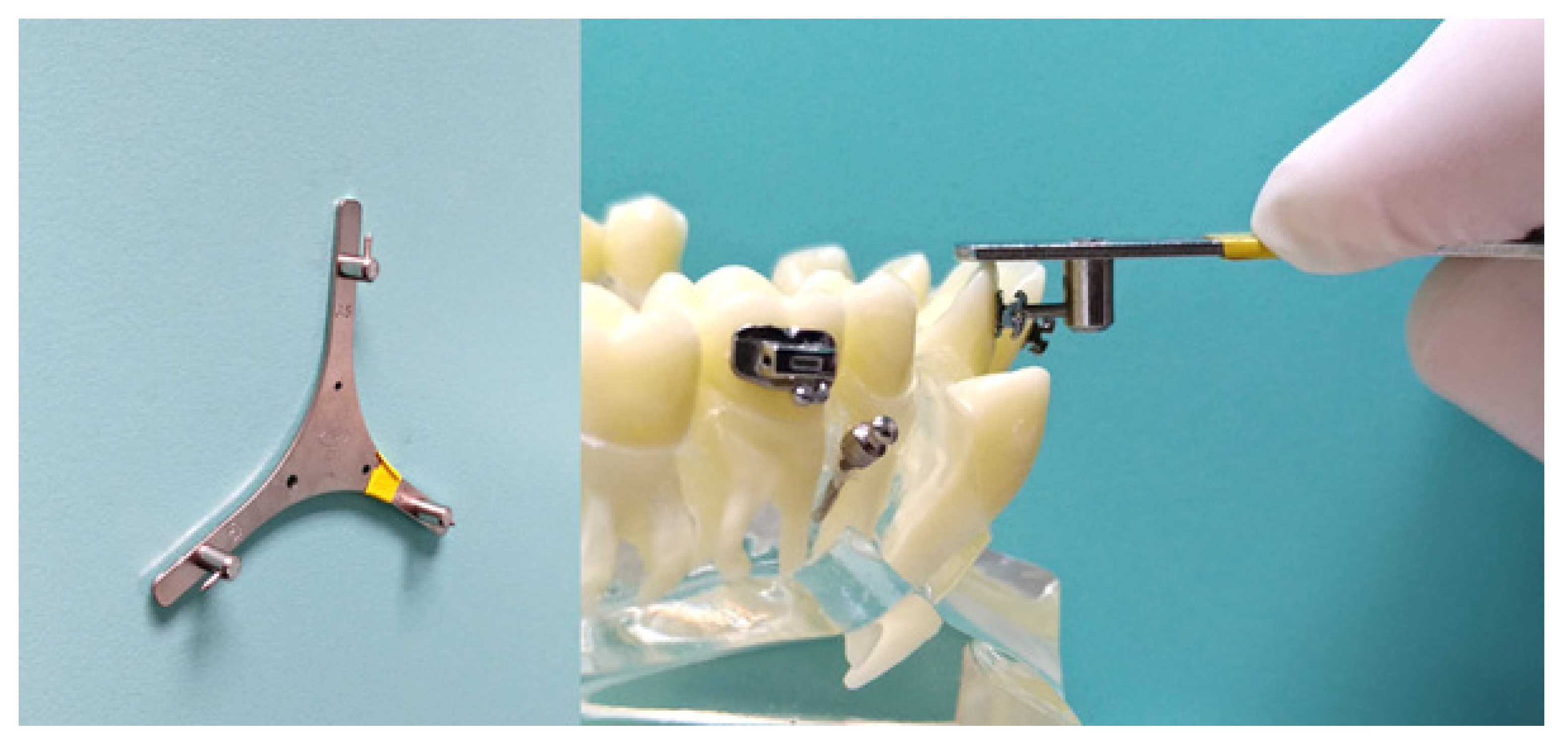
Figure 2). Before starting bracket placement, all teeth were scanned, and the ideal bracket position was analyzed using the intra-oral scanner (TRIOS 3 Basic, 3Shape Dental Systems, Copenhagen, Denmark) and digital modelling software(Ortho Analyzer, 3Shape Dental Systems, Copenhagen, Denmark). Pre-adjusted edgewise plastic brackets with an 0.018-inch slot (orthoEsther MB; Tomy) were bonded on the teeth. For bracket height measurement, the Boone gauge (G&H) was used in the control group (
Figure 3). With an interval of 0.5 mm, the ruler allows the measurement of bracket height at 0.35, 0.40, 0.45, and 5.0 mm. The AR-assisted bracket navigation system was adopted in the experimental group. After bracket bonding, all teeth were scanned, and the final bracket position was analyzed.
2.3. Method for Applying the AR-Assisted Bracket Navigation System
The AR-assisted bracket navigation system comprised two technical modules, namely the facial axis of the clinical crown (FACC) detection module and the bracket bonding navigation module. Collecting real-time images captured by the intraoral camera, the FACC module segmented the image of each tooth through computer-vision–based image analysis, thereby generating dental features that included the complete contour and FACC of each tooth. The bracket bonding navigation module overlapped the real-time image with the bracket bonding positions determined during preoperational planning, thereby achieving preoperational planning visualization.
2.3.1. FACC Detection Module
The FACC detection module performed morphological analysis to roughly segment the contour of the entire tooth. To accurately extract the detailed tooth contour, the GrabCut algorithm was adopted to facilitate interactive foreground extraction and fix the contour of each tooth. Specifically, the algorithm, targeting regions of interest in each tooth extracted from the morphological analysis, implemented foreground image segmentation using source and sink nodes, foreground–background separation, graph cuts, and energy function. During image segmentation, pixels were considered nodes, and these nodes comprised two types, namely source nodes and sink nodes. Source nodes represented the foreground image of regions of interest, whereas sink nodes indicated unwanted background image regions. This technique can create a great pixel difference on the edge of the target image, allowing the system to distinguish regional foregrounds from backgrounds, isolate the tooth contour, and achieve tooth segmentation [
14]. After extracting the contour of each tooth using real-time imaging, we extracted the bounding box of the closed contour formulated by each tooth to detect the anatomical FACC. For example, when segmenting the maxillary teeth, the tooth zenith can be identified along the upper side of the bounding box, whereas the bottom side denotes the incisor line. By connecting the zenith and incisor line, the FACC can be detected. The FACC, as defined by Andrews (1979), serves as a reference line in straight-wire appliance design. We adopted the FACC because it is highly rediscoverable and reliable as a reference line, susceptible to the surroundings, and unlikely to change in the entire lifetime; moreover, theaxis does not require X-ray imaging in clinical practice, and can be seen by the naked eye, thereby allowing direct observation during treatments [
15].
2.3.2. Bracket Bonding Navigation Module
In a limited space, the bracket bonding navigation module mapped the bracket position data (planned prior to the operation) to real-time images, during which the tooth contour and FACC information acquired by the FACC model was used, the problem of optical distortion was considered, and scale-ruler–based proportional measurement conversions were performed. The module could avoid operational interference and inconvenience caused by the use of positioning two-dimensional barcode; the module managed to transfer the bracket coordinates from a virtual space to actual space.
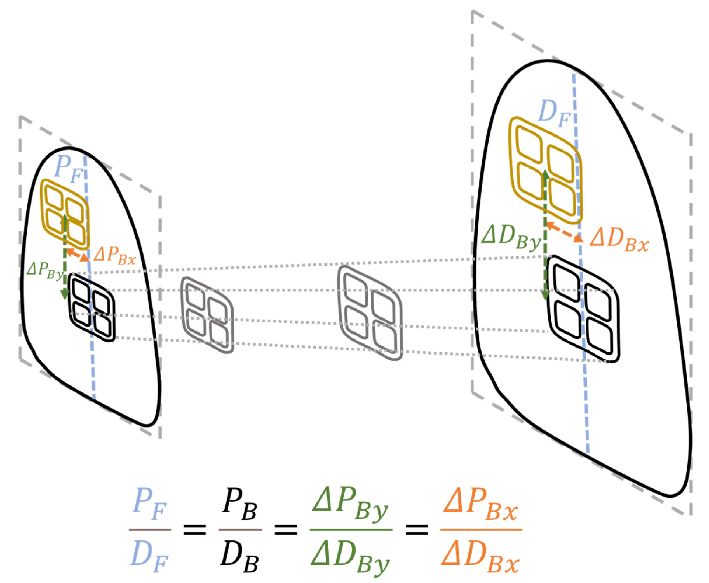
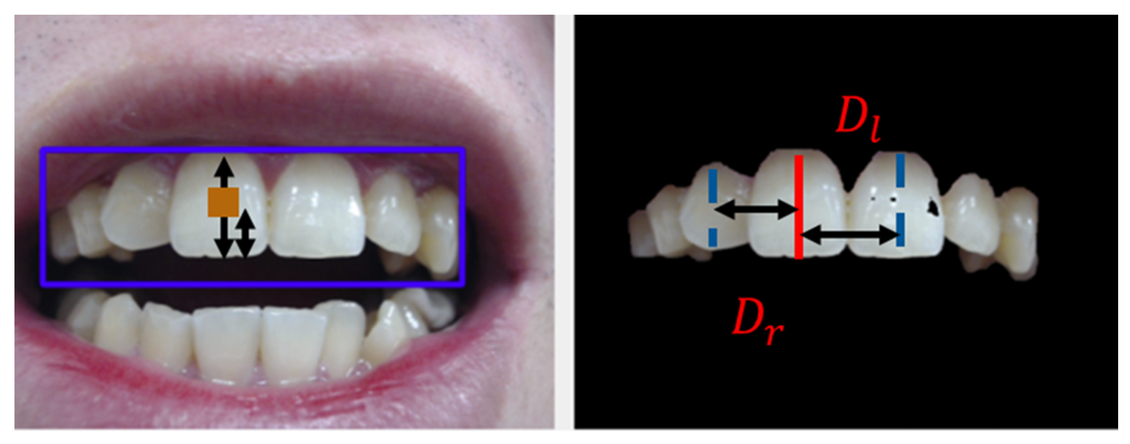
During scale conversion, the researchers had to identify the immovable hard tissues for the system to calculate the ratio of pixel to actual distance (
Figure 4). To do so, they obtained the mean of the left-to-target and right-to-target FACC distances for each tooth (
Figure 5). The present study regarded the FACC of neighboring teeth as the reference points because the FACC distance is less likely to be prone to cumulative errors caused by gingival changes and recession, missing information, and dental crowding. Furthermore, said mean could reduce unilateral measurement errors. Conversion was performed using the following equations:
where
F denotes the FACC,
B the bracket,
D the distance,
P the pixel,
r the right tooth, and
l the left tooth. The distance between the FACC of the target tooth and that of the right tooth is represented by
Pr pixels (
Dr mm), whereas the FACC of the target tooth and that of the left tooth are
Pl pixels (
Dl mm). The distance between the bracket and incisor line is denoted by
PB pixels (
DB mm).
2.4. Intraoral Scanner and Its Operations
An intraoral scanner (TRIOS 3 Basic, 3Shape Dental Systems, Copenhagen, Denmark) was used to record the oral status of participants. Following the manufacturer’s instructions, the scanner was calibrated prior to scanning with the lens preheated. High power suction was used to suck most of the saliva, after which the remaining saliva was dried using compression air. According to the procedures recommended by the scanner software, the scanning began with the occlusal surface from the left mandibular second molar to the right mandibular second molar. Next, the lingual surface was scanned, followed by the buccal surface. Similarly, the occlusal surface was scanned for the maxillary teeth, followed by the buccal surface and the palatal surface. When scanning the occlusal surface, the lens–tooth distance was fixed at 0–5 mm; when scanning the buccal surface and lingual surface, the camera was turned from 45° to 90°, during which the image capturing process was displayed on the monitor, thereby ensuring complete scanning without missing any blind spots. Following maxillary and mandibular teeth scanning, the centric occlusion positions were recorded, which comprised the positions of premolars and molars on both sides.
Data obtained through the aforementioned procedures were used for preoperational modeling and post-operational bracket bonding modeling. The scanner accuracy and consistency were 6.9 ± 0.9 µm and 4.5 ± 0.9 µm, respectively [
16].
2.5. Pretreatment Digital Setup and Planning of Bracket Positions
The intraoral scanner was also adopted to establish intraoral digital models of participants. Specifically, pretreatment digital models were applied for a virtual setup using the digital modeling software Ortho Analyzer (3Shape Dental Systems, Copenhagen, Denmark). A virtual setup, facilitated on software, can separate each tooth and move it to the planned position. According to the software program, unwanted and nonexistent tooth positions were excluded, after which the mesial and distal positions of each tooth were marked. Subsequently, the program semiautomatically marked the gingival margin of each tooth and allowed manual adjustment of unclear margins. After confirmation, the program defined proximal contact points according to the obtained gingival margin and mesiodistal direction. According to the six keys to normal occlusion proposed by Andrews et al. (1976; i.e., molar relationship, mesiodistal crown angulation, labiolingual crown inclination, no rotations, tight contacts, and a flat occlusal plane) [
17], we defined the final occlusion status. To avoid mesiodistal deviation of brackets causing crown rotation during treatment, we overlapped the Y axis with the FACC; the incisor line was regarded as a reference line for calculating the height of each bracket. The vertical positions of each bracket were then aligned with the final occlusion plane, namely Andrews’ plane [
15], to ensure correct bracket position marking as planned. After bracket planning was completed using 3D digital setup software, we obtained the absolute coordinates of each bracket on the tooth crown. The teeth and brackets could then be bounded using the developed AR-assisted bracket navigation system.
2.6. Clinical Procedure
Place the retractor in the patient’s mouth.
Clean the tooth surface with a low-speed brush and a polishing paste.
Dry the tooth surface (Do not etch the tooth surface and use the bonding agent).
Apply orthodontic adhesive (Orthomite LC; SunMedical) on the bracket base.
Place the bracket with the Boone gauge (control group)/AR system (experiment group).
Remove excessive adhesive.
Light cure each tooth for 20 s.
2.7. Assessment of Accurate Bracket Positioning
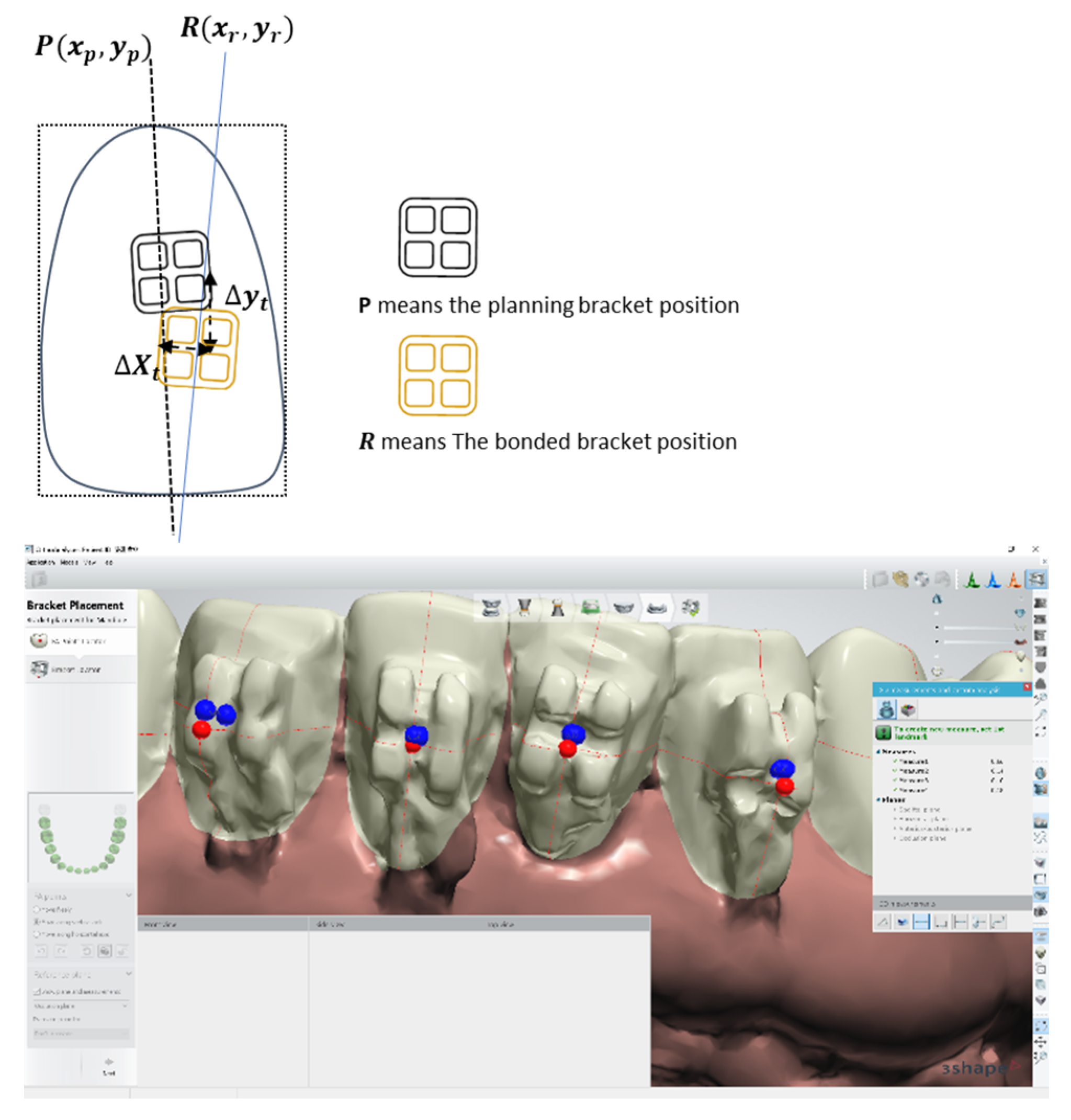
Ortho Analyzer was used to compare the preoperational bracket position plan and bonded bracket model through coordinate system quantification. The measurement parameters required were as follows: (1) The center of the bracket
P(
Xp,
Yp) in preoperational planning, with the preoperational planning position of each tooth as the origin; (2) the position of the bonded bracket
R(
Xr,
Yr); and (3) the horizontal deviation (
ΔXt) and vertical deviation (Δ
Yt) between the actual adherence position and planned position. The X axis denotes the mesiodistal direction, whereas the Y axis denotes the inciogingival direction (
Figure 6). The error of measuring position deviation ranged from—0.01 to 0.01 mm, with a mean (standard deviation [SD]) of 0.01 (0.001) mm.
2.8. The Reliability of AR–Assisted Bracket Navigation System
Next, the reliability of the AR system was verified. The resolution of the intraoral scanner was 640 × 640 pixels. In the preliminary test, when the operating distance was 12 mm, 33–35 pixels were observed every 10 mm, indicating an interval of 0.285–0.30 mm per pixel. When the effective operating distance increased, the number of pixels per unit also increased, creating little interval as well as high accuracy.
2.9. Statistical Analysis
Continuous variables are presented as the medium ± interquartile range (IQR). The Shapiro–Wilk test indicated that the variables were not normally distributed. The Mann–Whitney U-test was used to compare continuous variables between the novice and expert groups. The Wilcoxon sign rank test was used to compare continuous variables between the experiment and control groups. p < 0.05 was considered statistically significant. All statistical analyses were conducted using SPSS for Windows (version 12, SPSS, Chicago, IL, USA). A power analysis for Wilcoxon-Mann-Whitney test (two groups) conducted posteriori using G*Power 3.1.9.7 indicated 95% power to detect a small effect size at a significance level of 0.05.
4. Discussion
The ideal bracket position is vital for efficient orthodontic treatment. Many studies have discussed ideal positioning since 1976. Andrews introduced the bracketing technique of the straight wire concept, which involved placing the bracket up or down until the middle of the bracket slot base is at the same height as the mid-point of the clinical crown. [
7,
8,
9]
In the current study, we used initial digital modelling to predict the final setup to define each volunteer’s bracket position and measure the bracket height before transferring to the AR-assisted bracket navigation system.
Various methods have been proposed for ideal bracket positioning [
2,
12,
13,
18,
19,
20]. They can be divided into direct and indirect bonding techniques. The direct bonding technique uses a gauge to directly measure the ideal bracket positions in oral cavity. This technique has the advantages of no interference with the guiding tray, more acceptable for crowded teeth, and immediately adjustable bracket position. However, the direct bonding technique is influenced by the measure scale of gauge, tooth morphology, and operator’s experience. The indirect bonding technique uses a transfer tray to transfer the brackets into the intra-oral teeth. They are divided into 2 stages: The lab stage, which involves locating the bracket position on the stone model and fabricating a transfer tray to duplicate the bracket position, and the clinical stage, which involves setting the tray with brackets into the patient’s mouth. Therefore, the indirect bonding technique overcomes the limitation of the limited view in the oral cavity. Nevertheless, placement errors may occur depending on the transfer tray material, operator’s finger pressure, and technician skills. Several researchers have designed many types of transfer trays, including polyvinyl siloxane trays, vacuum-formed trays, 3-dimensional-printed stent, and transfer jigs [
11,
13,
18,
21,
22,
23]. AR-assisted bracket navigation system combines the advantage of both bonding techniques and overcomes the disadvantage.
Aichert et al. (2012) used digital volume tomography of a computed tomography scan to overlay the orthodontist bonded procedure video image by using an AR system in vitro, and the average error with their technique was 2.1 mm [
24]. By contrast, the average error in our study with novice and expert orthodontists was 0.51 mm and 0.29 mm, respectively, indicating significantly high accuracy. Our study has clinical significance because the clinically acceptable placement error is 0.5 mm. Furthermore, we used digital modeling with an intra-oral scanner to determine the bracket position, thus avoiding any radiation exposure due to computed tomography, unlike Aichertet al.’s study.
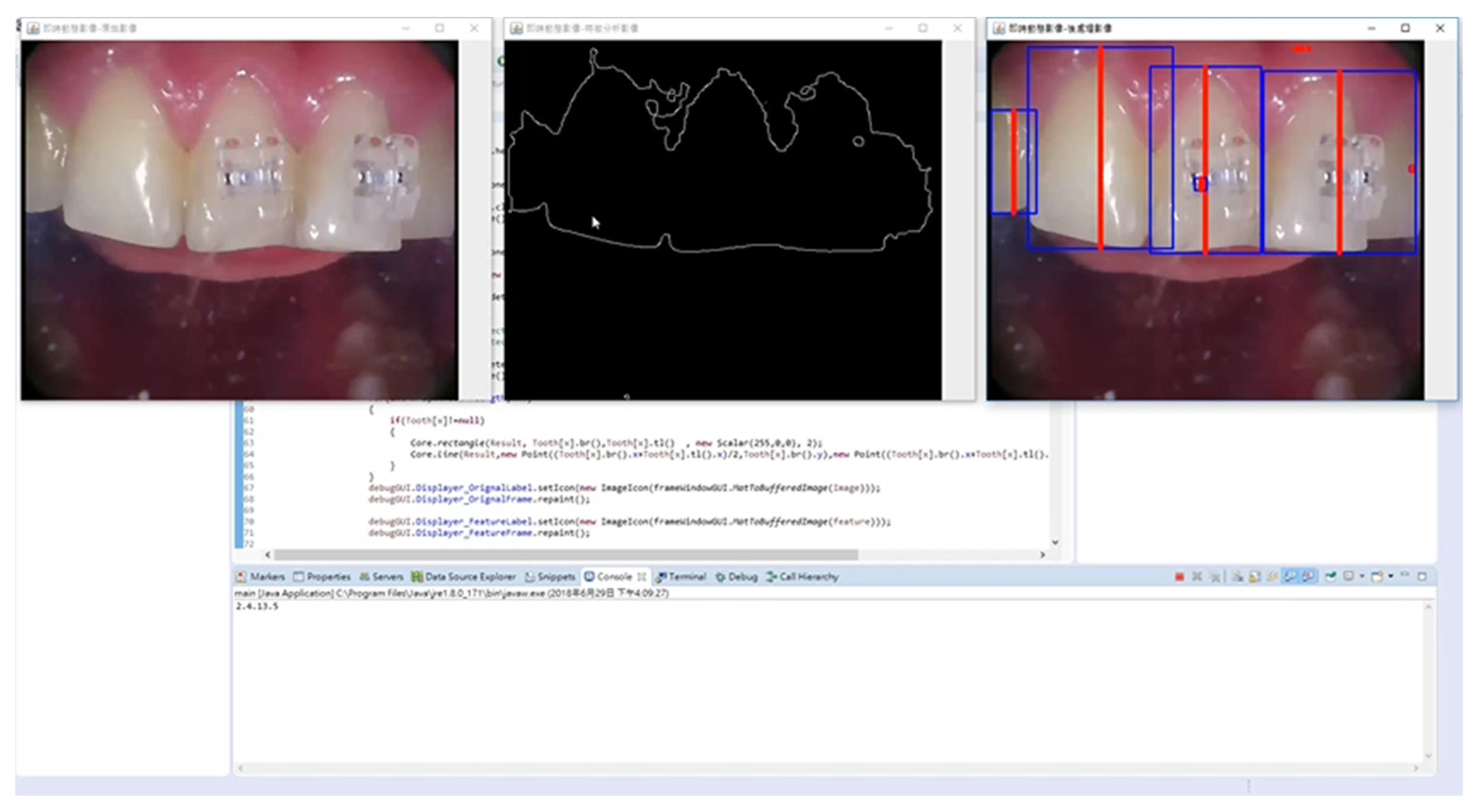
The device used a wireless handheld intra-oral camera to capture oral teeth image and sent it for data processing. The registration method used the real-time natural feature registration to superimpose the ideal bracket position of the virtual object on the tooth surface (
Figure 7).
We used the real-time corner detection algorithm to achieve real-world integrity and high registration accuracy [
3]. The AR-assisted bracket navigation system was displayed on the screen in front of the operator instead of a head-mounted device to reduce the load on the operator’s neck. Under acceptable error rate, the proposed system could provide more fluent user experience because there was no huge number of calculations that needed to be done within the limited time. As a result, deviations in the expert group in the vertical (incisogingival) direction were 0.40 mm and 0.29 mm for the control and AR groups, respectively, and the improvement rate was 28%. Deviations in the novice group were 0.90 mm and 0.51 mm, respectively, and the improvement rate was 43%. Notably, using the AR-assisted bracket navigation system, the accuracy of the novice orthodontist closed that of the expert orthodontist using the Boone gauge. However, no significant differences were observed in the horizontal (mesiodistal) direction regardless of the orthodontist’s experience or the system used.
The results showed no significant difference between the experimental group and the control group, and the possible reason is that the pre-treatment of root parallelism was not taken into consideration. However, the research is still valuable for clinical practice due to the fact that the horizontal deviations of the two methods were less than 0.5 mm.
The standard of 0.5 mm is regarded as the acceptable clinical limitation according to the professional standard of the American Board of Orthodontics Objective Grading System [
25]. This system recommends that the deviation of alignment and marginal ridges should be at the same level or within 0.5 mm [
25]. As reported by Castilla et al. (2014) [
26], who investigated the linear differences between five indirect bonding techniques, the deviation ranged between 0.06 mm and 0.49 mm [
26]. According to an in vivo study by Grünheid et al. (2015) [
13], statistical differences were confirmed under the 0.5 mm deviation limitation. The acceptable deviation in the present study was consistent with those in the two aforementioned studies.
Intraoral camera resolution plays a crucial role in the accuracy of bracket bonding when the AR-assisted bracket navigation system is used. The higher the resolution, the more detailed the information in the unit pixel. We proposed the feature-based facial axis of the clinical crown (FACC) detection algorithm to decrease the error in mapping the augmented information to the real image. We extracted the contour of each tooth from the color image based on the difference in the signal between the hard and soft tissue in the color space. Next, on the basis of the tooth contour, the incisor line and FACC—two crucial reference lines—were detected for each tooth using the proposed algorithm. The positions of the bracket on each tooth depended on these two reference lines. Thus, the system used indirect information to ensure the accuracy of the augmented information during mapping from the virtual world to the real world.
A high accuracy in bracket positioning can reduce the need for the first- and second-order bends, thus reducing treatment time and complexity, as well as reduce the clinical chair time required for bracket rebonding and leveling, thus ensuring efficient and precise treatment. The third-order bends are not discussed in our study because they are easily influenced by the high contour of tooth morphology, adhesive thickness, and position of bracket height.
One limitation of the device was not considering the root information of the facial tooth axis of the clinical crown. Adding the root information in the AR-assisted bracket navigation system might increase the accuracy in the horizontal (mesiodistal) direction. Another limitation was the inadequate fluency and optimization of the system. The system might benefit from hardware and software upgrades, including higher graphics processing unit, high-resolution delicate micro lens, higher internet transfer speed, algorithm optimizing, and intact image extraction technology.
Future studies should combine the AR-assisted bracket navigation system with artificial intelligence models for teeth image extraction [
27,
28,
29] and use a 5G technology for data transfer speed [
30], more efficient graphics processing unit, optimized algorithm, and high-resolution delicate micro lens, thereby increasing the accuracy and reliability. This AR system can have many applications in dentistry, including temporary anchorage devicesnavigation system, root parallel information display, and Bolton analysis [
31]. The present study represents just the beginning of AR application in the orthodontic field [
32]. Many clinical treatments can use the AR system, which will make treatments safer and more efficient.
