
Design and Experimental Evaluation of a Form Trimming Machine for Horticultural Plants


Abstract
1. Introduction
2. Design of the Form Trimming Machine
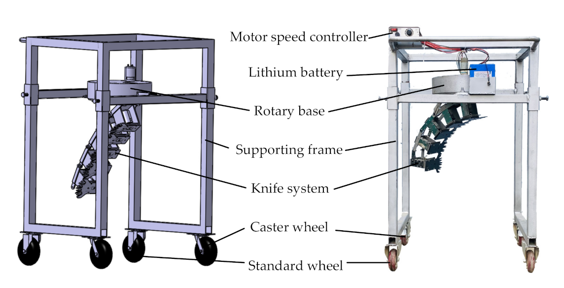
2.1. Oveall Structure and Working Principle
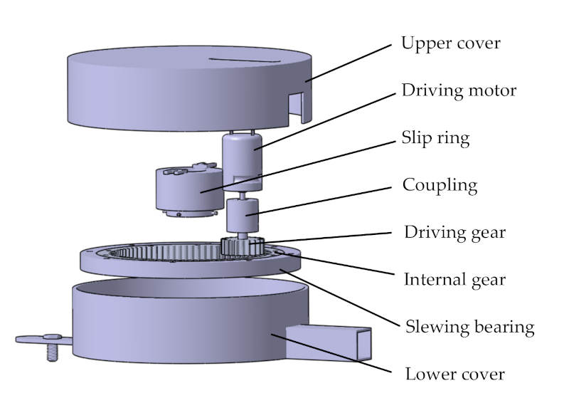
2.2. Rotary Base
2.3. Knife System
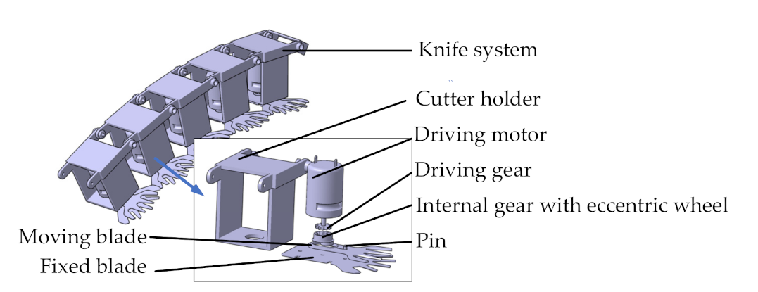
2.3.1. Structure
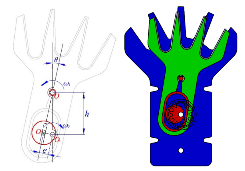
2.3.2. Principle of the Cutting Motion of Blades
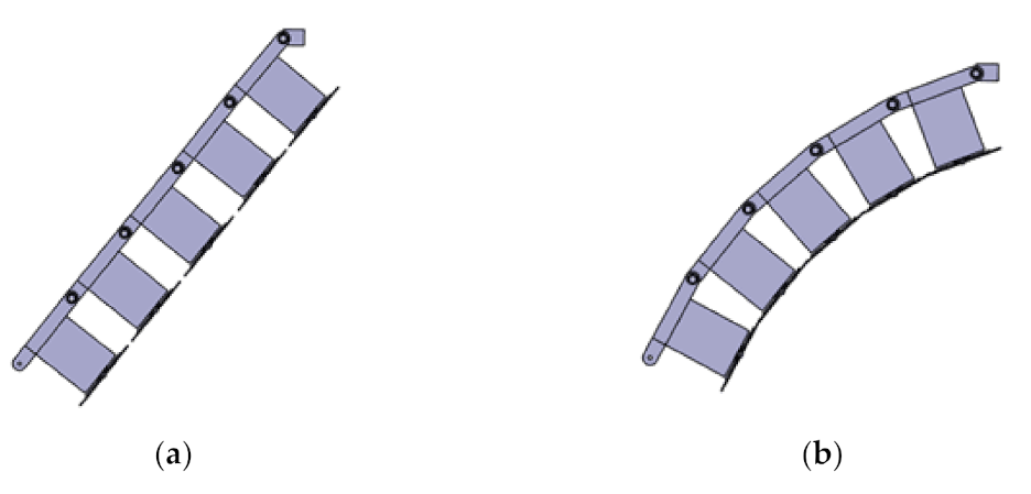
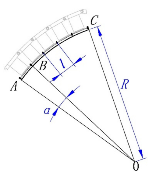
2.3.3. Determination of the Number of Cutter Units
2.3.4. Determination of the Driving Motor Speed
3. Experiments
3.1. Determination of the Cutting Frequency of the Cutter Unit
3.2. Determination of the Rotating Speed of the Rotary Base
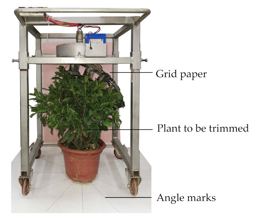
3.3. Adaptability Test
4. Results and Discussion
4.1. Determination of the Cutting Frequency of the Cutter Unit
4.2. Determination of the Rotating Speed of the Rotary Base
4.3. Adaptability Test
5. Conclusions
- (1)
- The two key working parameters, the cutting frequency of the cutter unit and the rotating speed of the rotary base, were determined to be 16.7 Hz and 13.5 r/min respectively. The trimming operation could be completed by two rotations of the knife system with a time consumption of 8.89 s.
- (2)
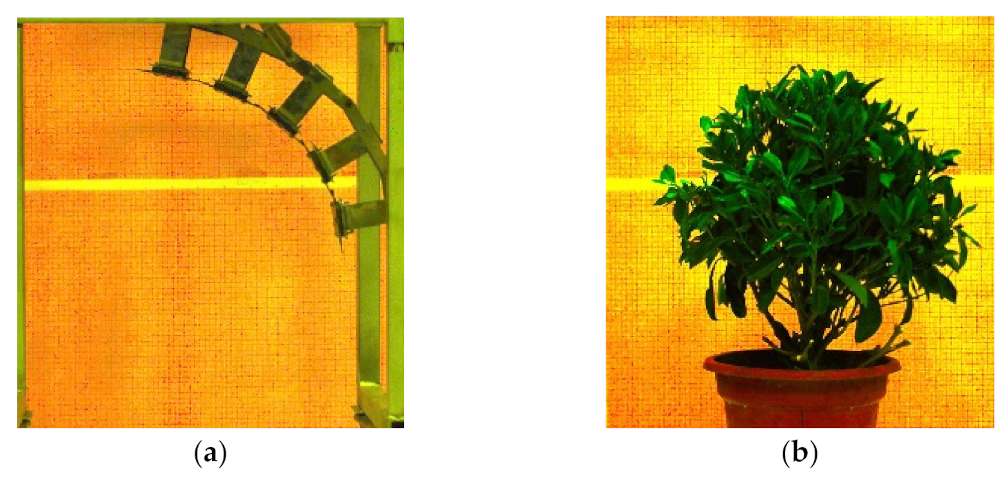
- Through a performance evaluation using a photography system and an imaging processing method, the similarities between the profile of the knife system and the profile of the trimmed plants were calculated. An overall similarity of 96% was obtained when the machine was tested to trim Fagraea ceilanica plants.
- (3)
- Through an adaptability test using five different species of shrub plants, the overall similarity was above 93%, which showed that the designed machine could meet the requirement of trimming various shrub plants with stable performance.
6. Patent
Author Contributions
Funding
Data Availability Statement
Acknowledgments
Conflicts of Interest
References
- Chen, C.; Park, T.; Wang, X.; Piao, S.; Xu, B.; Chaturvedi, R.K.; Fuchs, R.; Brovkin, V.; Ciais, P.; Fensholt, R.; et al. China and India lead in greening of the world through land-use management. Nat. Sustain. 2019, 2, 122–129. [Google Scholar] [CrossRef]
- National Romote Sensing Center of China (NRSCC). Global Urban Land Composite and Expansion in 2000–2020. Available online: http://www.chinageoss.cn/geoarc/en/pdf/2020C_en.zip (accessed on 6 February 2021).
- Gokavi, N.; Mote, K.; Jayakumar, M.; Raghuramulu, Y.; Surendran, U. The effect of modified pruning and planting systems on growth, yield, labour use efficiency and economics of Arabica coffee. Sci. Hortic. 2021, 276, 109764. [Google Scholar] [CrossRef]
- Wei, X.; Chen, D.; Liu, S.; Wang, X.; Gao, Z.; Wang, Y. Effect of trim on jujube transpiration in loess hilly region. Trans. Chin. Soc. Agric. Mach. 2014, 45, 194–202. [Google Scholar]
- Pineda, M.; Yu, B.; Tian, Y.; Morante, N.; Salazar, S.; Hyde, P.T.; Setter, T.L.; Ceballos, H. Effect of pruning young branches on fruit and seed set in cassava. Front. Plant Sci. 2020, 11, 1107. [Google Scholar] [CrossRef] [PubMed]
- Sun, J.; Gao, H.; Tian, J.; Du, C.; Guo, S. Development status and trends of protected horticulture in China. J. Nanjing Agric. Univ. 2019, 42, 594–604. [Google Scholar]
- Reddy, K.A.; Babu, N.M.; Harini, L.; Srikanth, R.; Srinivas, J. Design and analysis of a revised grass trimming device. J. Sci. Ind. Res. 2010, 69, 39–42. [Google Scholar]
- Mallick, Z. Optimization of operating parameters for a back-pack type grass trimmer. Int. J. Ind. Ergon. 2008, 38, 101–110. [Google Scholar] [CrossRef]
- Pandiselvam, R.; Manikantan, M.R.; Subhashree, N.; Mathew, A.C.; Balasubramanian, D.; Shameena Beegum, P.P.; Ramesh, S.V.; Niral, V.; Ranjini, T.N.; Hebbar, K.B. Correlation and principal component analysis of physical properties of tender coconut (Cocos nucifera L.) in relation to the development of trimming machine. J. Food Process Eng. 2019, 42, e13217. [Google Scholar] [CrossRef]
- Sitorus, A.; Fauzi, A.; Ramadhan, G.; Hasan, A.R.; Karyadi, A. Conceptual Design of Harvesters Knife for Chinese Spinach (Ipomoea Reptans Poir.): Cad Approach. 2018 International Conference on Computing, Engineering, and Design (ICCED), Bangkok, Thailand, 6–8 September 2018; pp. 7–12. [Google Scholar] [CrossRef]
- Fujisawa, A.; Chida, Y. Optimization of an installation angle of a root-cutting blade for an automatic spinach harvester. J. Phys. Conf. Ser. 2016, 744, 012135. [Google Scholar] [CrossRef]
- Tuijl, V.B.A.J.; Tielen, A.P.M.; Mencarelli, A.; Hemming, J. Structured design of a novel end-effector for a bush trimming robot. In Proceedings of the European Conference on Agricultural Engineering AgEng2018, Wageningen, The Netherlands, 8–12 July 2018; pp. 188–196. [Google Scholar]
- Kaljaca, D.; Vroegindeweij, B.; Mencarelli, A.; van Henten, E. Coverage trajectory planning for a bush trimming robot arm. J. Field Robot. 2020, 37, 1148. [Google Scholar] [CrossRef]
- Qiu, J.; Wu, M.; Guan, C.; Fang, Y.; Li, X. Design and experiment of chopping device with dynamic fixed knife coaxial for rice straw. Trans. Chin. Soc. Agric. Eng. 2015, 31, 11–19. [Google Scholar]
- Lin, J.; Ma, T.; Lu, Z.; Li, B.; Song, J.; Lv, Q. Design and experiment of the surveying and mapping device for the movement characteristics of corn stubble cutting with disc cutting knife. Agric. Res. Arid Areas 2017, 35, 271–281. [Google Scholar]
- Yang, Y.; Xu, J.; Wang, J.; Zhang, Q.; Liu, Q. Design of a new chopper for corn stalk and wear test of its moving knives. J. Jilin Agric. Univ. 2010, 32, 468–472. [Google Scholar]
- He, L.; Schupp, J. Sensing and automation in pruning of apple trees: A Review. Agronomy 2018, 8, 211. [Google Scholar] [CrossRef]
- Strnad, D.; Kohek, S.; Benes, B.; Kolmanic, S.; Zalik, B. A framework for multi-objective optimization of virtual tree pruning based on growth simulation. Expert Syst. Appl. 2020, 162, 113792. [Google Scholar] [CrossRef]
- Zahid, A.; He, L.; Zeng, L.; Choi, D.; Schupp, J.; Heinemann, P. Development of a robotic end-effector for apple tree pruning. Trans. ASABE 2020, 63, 847–856. [Google Scholar] [CrossRef]
- Souza, V.H.S.; Santos, A.A.R.; Costa, A.L.G.; Santos, F.L.; Magalhaes, R.R. Evaluation of the interaction between a harvester rod and a coffee branch based on finite element analysis. Comput. Electron. Agric. 2018, 150, 476–483. [Google Scholar] [CrossRef]
- Wu, L.; Yang, Z.; Duan, J.; Wang, L.; Wang, W.; Liu, J.; Wang, L. Experiment on influencing factors of cutting force of blades of trim tool for longan branch. Trans. Chin. Soc. Agric. Eng. 2012, 28, 8–14. [Google Scholar]
- Jarimopas, B.; Ruttanadat, N.; Terdwongworakul, A. An automatic trimming machine for young coconut fruit. Biosyst. Eng. 2009, 103, 167–175. [Google Scholar] [CrossRef]
- Chen, C.; Wang, X.; He, Z. Design of header for rape harvesting using grain combine harvester. Trans. Chin. Soc. Agric. Mach. 2003, 34, 54–56. [Google Scholar]
- Li, P.; Liao, Q.; Li, L.; Han, C.; Huang, P.; Li, H. Design and experiment of the main device of 4SY-1.8 modified rape windrower. Trans. Chin. Soc. Agric. Mach. 2014, 45, 53–58. [Google Scholar]
- Liu, W.; Huang, X.; Ma, L.; Zong, W.; Zhu, Y. Design and experiment of special header of oil sunflower combine harvester. Trans. Chin. Soc. Agric. Mach. 2020, 51, 83–88. [Google Scholar]
- Johnson, P.C.; Clementson, C.L.; Mathanker, S.K.; Grift, T.E.; Hansen, A.C. Cutting energy characteristics of Miscanthus x giganteus stems with varying oblique angle and cutting speed. Biosyst. Eng. 2012, 112, 42–48. [Google Scholar] [CrossRef]


| Parameter | Value (Unit) |
|---|---|
| Overall dimensions (length × width × height) | 680 × 725 × 1075 mm |
| Total weight | 53.5 kg |
| Knife system weight | 4.9 kg |
| Adjustable height range | 0~925 mm |
| Maximum plant size | 700 mm |
| Power requirement | 24 VDC |
| Plant | Average Diameter of Branches (mm) | Average Moisture Content of Branches (%) |
|---|---|---|
| Aglaia odorata | 3.61 | 47.07 |
| Murraya paniculate | 3.54 | 50.26 |
| Camellia oleifera | 3.73 | 40.92 |
| Osmanthus fragrans | 3.74 | 39.52 |
| Radermachera sinica | 3.65 | 45.03 |
| Rotating Speed (r/min) | Cutting Frequency (Hz) | Branch Diameter (mm) | ||||
|---|---|---|---|---|---|---|
| 1.2 | 2.5 | 3.4 | 4.5 | 5.4 | ||
| 450 | 7.5 |  Cut off |  Cut off by multiple runs |  No cut off | No cut off | No cut off |
| 650 | 10.8 | Cut off |  Cut off by multiple runs |  No cut off | No cut off | No cut off |
| 850 | 14.2 | Cut off |  Cut off |  Cut off by multiple runs |  No cut off |  No cut off |
| 1000 | 16.7 | Cut off | Cut off |  Cut off |  Cut off |  No cut off |
| Rotating Speed (r/min) | Trimming Circle | Time Consumed (s) | Similarity (%) |
|---|---|---|---|
| 7.5 | 2 | 16 | 96.38 |
| 10.5 | 2 | 11.43 | 96.18 |
| 13.5 | 2 | 8.89 | 96.45 |
| 16.5 | 3 | 10.91 | 96.01 |
| 19.5 | 4 | 12.31 | 97.67 |
| Plant | Aglaia odorata | Murraya exotica | Camellia oleifera | Osmanthus fragrans | Radermachera sinica |
|---|---|---|---|---|---|
| Form before trimming |  |  |  |  |  |
| Form after trimming |  |  |  |  |  |
| Similarity (%) | 94.87 | 93.79 | 94.32 | 94.95 | 95.49 |
Publisher’s Note: MDPI stays neutral with regard to jurisdictional claims in published maps and institutional affiliations. |
© 2021 by the authors. Licensee MDPI, Basel, Switzerland. This article is an open access article distributed under the terms and conditions of the Creative Commons Attribution (CC BY) license (http://creativecommons.org/licenses/by/4.0/).
Share and Cite
Li, M.; Ma, L.; Zong, W.; Luo, C.; Huang, M.; Song, Y. Design and Experimental Evaluation of a Form Trimming Machine for Horticultural Plants. Appl. Sci. 2021, 11, 2230. https://doi.org/10.3390/app11052230
Li M, Ma L, Zong W, Luo C, Huang M, Song Y. Design and Experimental Evaluation of a Form Trimming Machine for Horticultural Plants. Applied Sciences. 2021; 11(5):2230. https://doi.org/10.3390/app11052230
Chicago/Turabian StyleLi, Mao, Lina Ma, Wangyuan Zong, Chengming Luo, Muchang Huang, and Yang Song. 2021. "Design and Experimental Evaluation of a Form Trimming Machine for Horticultural Plants" Applied Sciences 11, no. 5: 2230. https://doi.org/10.3390/app11052230
APA StyleLi, M., Ma, L., Zong, W., Luo, C., Huang, M., & Song, Y. (2021). Design and Experimental Evaluation of a Form Trimming Machine for Horticultural Plants. Applied Sciences, 11(5), 2230. https://doi.org/10.3390/app11052230