1. Introduction
Differing from general vehicles operating on prepared roads, special vehicles equipped with tracked chassis are designed for negotiating harsh terrains. The irregular loads and impacts transmitted from such uneven terrains lead to maneuverability loss and ride performance degradation. Hence, the hydropneumatic suspension is widely used in off-road tracked vehicles, not only because of its good non-linear elastic stiffness and superior damping performance [
1] but also for the high-power density with lightweight. With such good properties, the tracked vehicles can better handle the conflict between the ride comfort and handling stability than ordinary trailing arm suspension [
2,
3].
The characteristics of hydropneumatic suspension have already attracted wide research attention in wheeled vehicles. Yin et al. [
4] studied the hydropneumatic suspension implemented on the front axle of an articulated vehicle by sensitivity analysis and optimization for the design parameters. The results suggested that the hydropneumatic suspension can help preserve directional stability and reduce driving vibration by nearly
. Nieto et al. [
5] presented an analytical model of air spring suspensions and obtained its first-order Taylor series linearized model, both of which are validated with experimental measurements. Gobbi et al. [
6] discussed the hydropneumatic suspension characteristics of a 6 × 6 amphibious vehicle. A mathematical model of the whole vehicle, including thermal transfer of the actuator and the hydraulic circuit, has been realized and experimentally tuned. Martini et al. [
7] presented a highly non-linear hydropneumatic suspension with strong regressive spring stiffness for motorcycles. By connecting the hydropneumatic suspension and the spring in series, the grip can be increased while ensuring that the comfort level is basically unaltered. These publications based on wheeled vehicles provide effective theoretical methods and models for the research of hydropneumatic suspension for tracked vehicles.
Current studies on the hydropneumatic suspension of tracked vehicles mainly focus on heavily armored vehicles. Cho and Lee [
8] investigated the non-linear elastics and the damping characteristics of an in-arm hydropneumatic suspension unit (ISU). The results showed that the desirable vertical displacement could be achieved by adjusting both the orifice diameter and pre-displacement of disc springs. Solomon and Padmanabhan [
9] validated the mathematical model of a hydro-gas suspension with experimental data. This model was incorporated in an in-plane model and the influence of suspension parameters were studied for different sinusoidal inputs. Although different hydropneumatic suspension designs and configurations have been proposed, their ride performance analysis methods still rely on the traditional analysis methods served for wheeled vehicles.
The systematic dynamics research for the ride performance analysis on various road surfaces of tracked vehicles started in the 1990s. Wong [
10,
11] and McCullough and Huang [
12] systematically derived tracked vehicle dynamics models which considered the mobility over soft terrains, ride dynamics over rough surfaces and maneuverability. They also studied the ride quality of tracked vehicle over deformable terrains. Dhir and Shankar et al. [
13,
14] developed a ride dynamic simulation model of a typical tracked vehicle assuming constant vehicle speed and non-deformable terrain surface. The wheel/track-terrain interactions and dynamic track loads were also taken into consideration. Ata et al. [
15] conducted a theoretical investigation into the effect of suspension configurations on a tracked vehicle performance over bump terrains. The suspension configurations, especially the numbers and locations of suspension dampers, were found to have a significant effect on vehicle mobility. Thanks to the rapid development of advanced computational tools, such as LMS Motion, Adams ATV and Recurdyn, multi-body dynamics (MBD) simulations have been widely used to rapidly predict the dynamic response of tracked vehicles in distinct virtual environments [
16,
17].
Unlike large tracked vehicles with ample design space, small and medium-sized tracked vehicles often adopt simple spring-damper suspension or just rigid chassis [
18,
19]. This paper proposes a novel compact tracked chassis with multi-cylinder hydropneumatic suspension to replace the conventional wheeled chassis of road-rail vehicles. Compared with the chassis driven by rubber wheels, tracked chassis can flexibly cope with the diverse rough terrains along the railway and switch operation modes without terrain restrictions to meet the growing needs of routine inspection and maintenance.
In this paper, a compact tracked chassis with a hydropneumatic suspension system is proposed, modelled, and evaluated. The main contributions are listed as follows:
A novel road-rail vehicle equipped with a tracked chassis is designed with the capability of autonomously switching between two operation modes and adapting to the various rugged and uneven terrains along the railway;
Lugre friction model is integrated with the hydropneumatic suspension model to improve the model accuracy. The suspension model is experimentally verified by the test rig data for a further establishment of the integral vehicle model;
The hydraulic and pneumatic parameters are optimized based on a systematic objective function, which takes into account the heave and pitch motion states for achieving better dynamic performance of the vehicle.
This paper is organized as follows. An overview of the proposed novel road-rail vehicle is presented in
Section 2;
Section 3 elaborates the design principle and the hydropneumatic suspension modelling.
Section 4 and
Section 5 report the model validation process and the ride performance analysis, respectively; Finally,
Section 6 concludes this paper.
2. Overview of the Road-Rail Vehicle
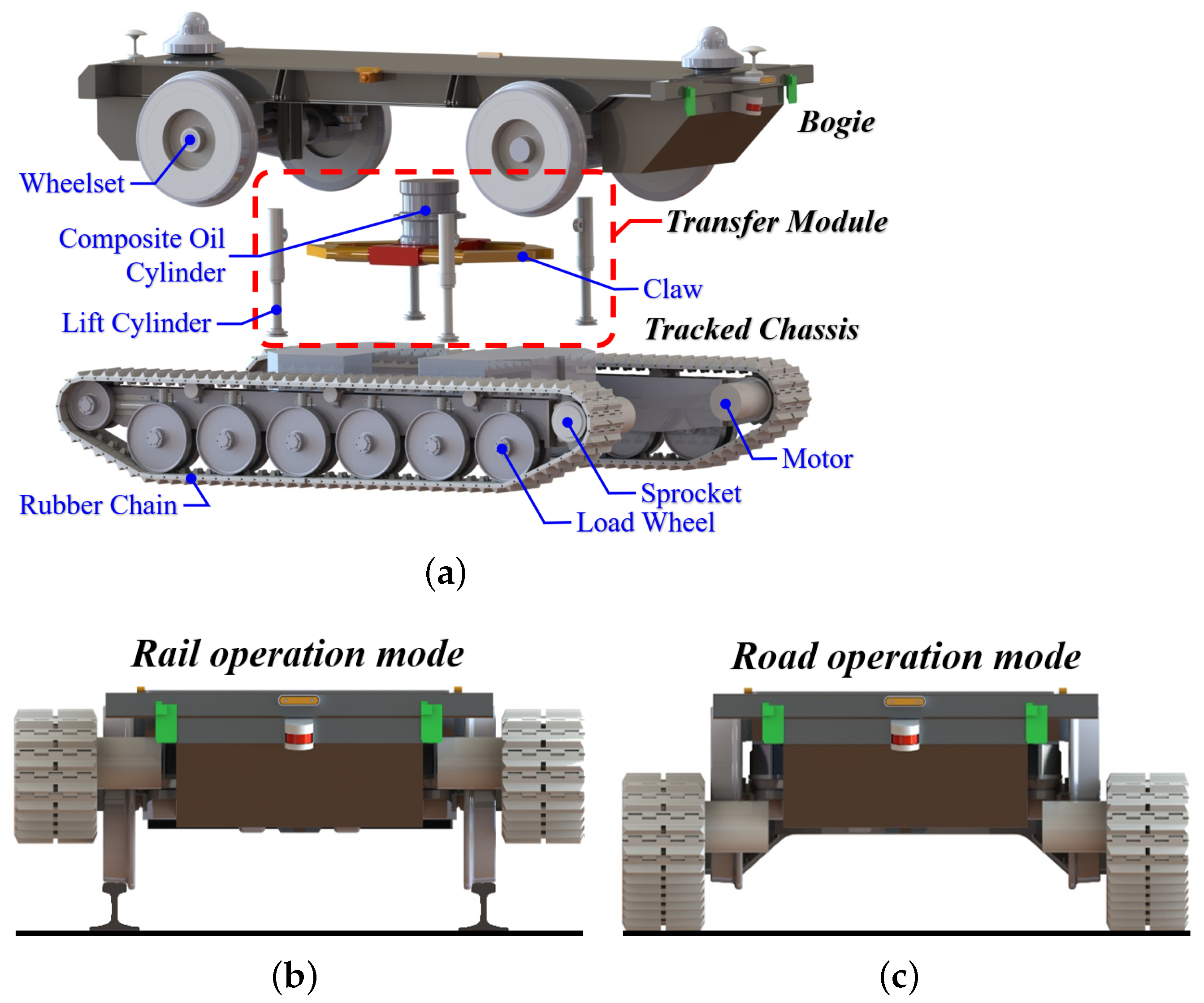
The overall compact design of the novel road-rail vehicle can be seen in
Figure 1a. As shown in
Figure 1a, this proposed vehicle consists of one tracked chassis, one bogie and a transfer module set.
Figure 1b,c illustrate that the bogie and the tracked chassis are applied as the chassis for rail driving and road driving, respectively. The transfer module is responsible for the switching between two operation modes, which comprises one composite oil cylinder, one rotatable claw and four lift cylinders. The composite oil cylinder connected with claw is mounted on the bogie, which can hold up and rotate the whole vehicle. The lower ends of the lift cylinders are mounted on the tracked chassis, and the upper ends are connected to the bogie so that the lifting cylinders can change the distance between the bogie and the tracked chassis.
For the rail operation mode, the wheelsets on the bogie ride on the rails and high-pressure oil will be pumped into the lower chambers of the four lift cylinders to lift the tracked chassis (with load wheels and pedrails) to leave the ground.
For the road operation mode, the left and right sprockets are driven by two motors, respectively. High-pressure oil will be pumped into the upper chambers of the four lift cylinders to raise the bogie and ensure the tracked chassis has sufficient ground clearance.
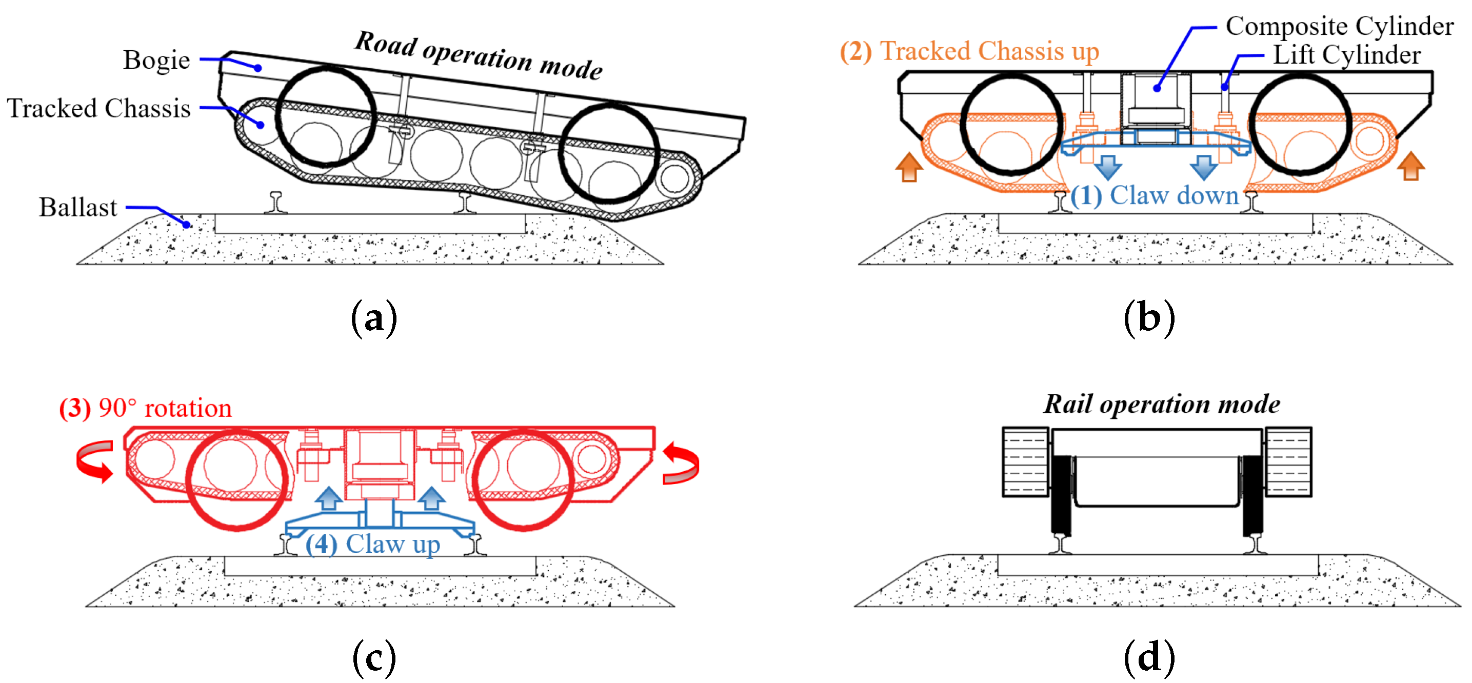
The switching from road operation mode to rail operation mode will be explained in the following.
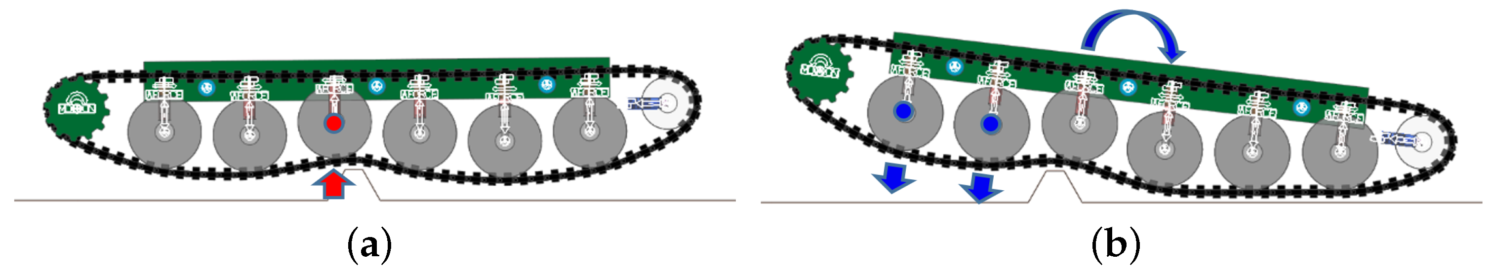
Figure 2a illustrates the body attitude change during the climbing process. The vehicle approaches the rails perpendicularly in road operation mode and moves slowly to reduce the impact. When approaching the railway, the vehicle adjusts its orientation to ensure that both pedrails can touch the rail almost simultaneously. The vehicle continues to move forward after both pedrails contact with the second rail and finally stops when it arrives at the middle of two rails.
Figure 2b,c show the process of operation mode switching. (1) The composite cylinder will lower the claw first. After the claw tightens to the rails, the composite cylinder will raise the whole vehicle. (2) Then four lift cylinders will lift the tracked chassis. The load wheels can be further lifted by the suspension system. (3) After that, the composite cylinder will turn the vehicle by 90 degree to align the vehicle along the rail direction. (4) The claw will be retrieved, and the wheelsets will ride on the rails. The operation mode switching is then completed, as shown in
Figure 2d. Next, the vehicle will be driven by the bogie.
3. Suspension Design and Modelling
This section introduces the design principle and layout of the hydropneumatic suspension system of the tracked chassis. This novel road-rail vehicle has two sets of suspension systems. Since the suspension system of the bogie has been studied in the previous paper [
20], the suspension system mentioned in the following all refers to the hydropneumatic suspension system of the tracked chassis.
3.1. Suspension Design of the Tracked Chassis
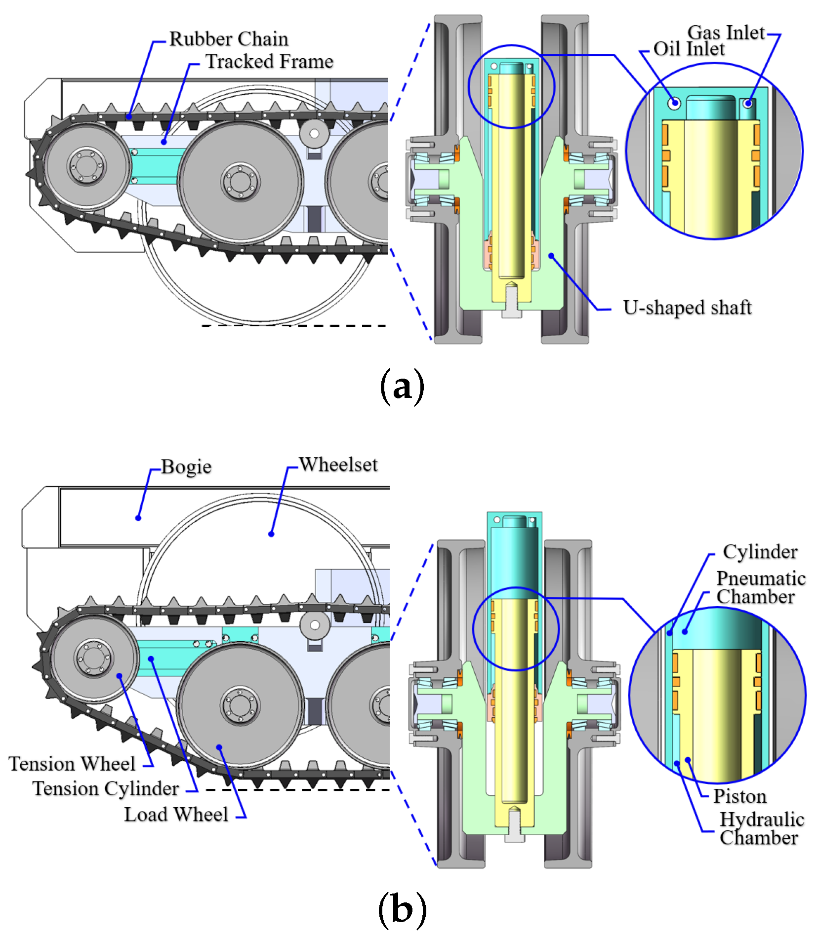
Figure 3 shows the structure of the cylinder-piston assembly and the suspension status in two operation modes. The suspension is mainly composed of an upper pneumatic chamber and a lower hydraulic chamber. The hydropneumatic cylinder-piston assemblies connect the load wheels to the tracked frame. The lower end (piston) is mounted on the U-shaped shaft with a load wheel. The upper end (cylinder) is fixed with the tracked frame. It should be emphasized that the design of the U-shaped shaft increases the total stroke of the suspension compared to the traditional unbent shaft. This design overcomes the height limitation of the tracked chassis and significantly reduces the risk of suspension breakdown.
As shown in
Figure 3a, the whole tracked chassis is wholly suspended during the rail operation mode. The oil is injected into the hydraulic chamber as the filling medium and push the piston to the top of the cylinder so that the load wheel does not produce vertical vibration affecting the driving stability of the vehicle.
During the road operation mode as shown in
Figure 3b, the pneumatic chamber is filled with nitrogen as an elastic medium, which provides a non-linear suspension stiffness. The hydraulic chamber is filled with oil, which provides a suspension damping. When driving on the ballasts or the terrains beside the rail, the bounce displacement of the load wheel is small, the suspension stiffness is low, and the vehicle has good driving stability. When crossing the barriers such as the rail and the ramp, the load wheel’s stroke becomes large, so strong shock absorption capacity and high reliability could be achieved.
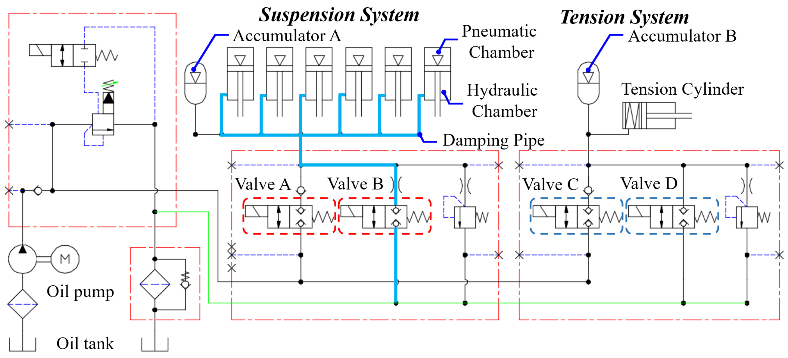
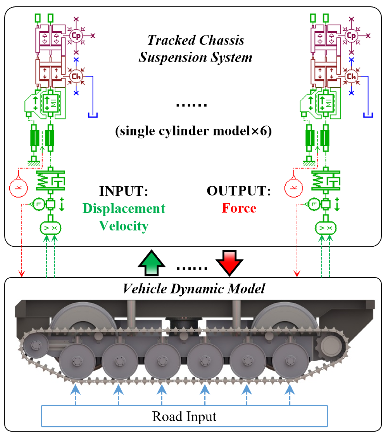
The hydropneumatic suspension system of the in-plane model is illustrated in
Figure 4. When valve B opens and valves A, C, D close, the hydraulic chamber is directly connected to the oil tank and the suspension system is working in road operation mode. When valves A, C open and valves B, D close, the oil pump supplies oil to the hydraulic chamber and the tension cylinder simultaneously. The gas in the pneumatic chamber is compressed and the load wheels are lifted.
When the load wheels reach the limit position, valve A closes. The pressure in accumulator A ensures that the load wheels maintain the limit position; The tension cylinder is stretched to ensure that the pedrails are not slack. When the tension force reaches a limit value, valve C closes and accumulator B will hold the tension pressure.
3.2. Modelling of the Hydropneumatic Suspension
An entire hydropneumatic suspension system, composed of the pneumatic chamber model, the damping pipe model, and the friction model, is established with non-linear features by AMESim. To study the overall dynamics and discuss the ride performance of the tracked chassis, a single-cylinder model needs to be investigated first.
Many scholars [
21,
22,
23] have established mathematical models for the pneumatic chamber model and the oil damping model of the hydropneumatic suspension. However, the friction is either neglected or taken as the simple Coulomb friction, which has a significant deviation on the model precision since friction is one of the primary sources of non-linear characteristics in the hydropneumatic suspension system.
3.2.1. Mathematical Model of the Actuation Cylinder
Assumptions are Made as Follows in the Proposed Model:
All parts of the cylinder have been effectively sealed. No gas dissolved into the oil;
The cylinder components are rigid since the working pressure only varies within a range of 40 bar in the pneumatic chamber;
The oil is incompressible since the oil is just the damping medium in this system;
The mass and the inertia of the oil is negligible.
The exerted force of suspension in this test rig is related to gas pressure
in the pneumatic chamber, oil pressure
in the hydraulic chamber, and seal element friction force
.
where
and
are the sectional areas of the pneumatic and hydraulic chambers, respectively.
3.2.2. Model of the Pneumatic Chamber
The pneumatic chamber of the cylinder is filled up with pressurized nitrogen and can be regarded as a gas spring. The corresponding gas pressure and gas volume are given by the polytropic process equation:
where
n is the polytrophic index,
and
are the pre-charge pressure and volume of the pneumatic chamber,
and
are the actual initial gas pressure and volume, respectively,
is the volume change of gas. It needs to be emphasized that
is determined by the weight of the vehicle, so it is constant in this paper.
If the oil flows quickly with the reciprocating motion of the piston, the polytrophic index
n is
based on the adiabatic thermodynamic process. Inversely, the thermodynamic process is the isothermal process and
. The polytropic exponent
n is set as
based on the practical application [
17].
3.2.3. Model of Damping Pipe
The damping force of the suspension system is mainly derived from the pressure loss generated by sudden changes in the flow cross-section. The pressure loss between the hydraulic chamber and the oil tank is composed of the partial pressure loss and the pressure loss along the pipe.
Hydraulic chamber pressure
can be expressed as:
where
and
are the density and flow velocity of the oil,
Q is the flow rate,
is the sectional area of damping pipe,
and
are the pressure distribution coefficient of oil outflow and inflow,
l and
d are the length and diameter of damping pipe,
v is the velocity of the piston relative to the cylinder.
is the flow restriction coefficient along the pipe:
the Reynolds number is defined as:
and the sign function is given as:
where
is the oil kinematic viscosity. The associated initial values of hydropneumatic variables are listed in
Table 1.
3.2.4. Lugre Friction Model
For the hydropneumatic suspension system, the friction force generated by the seal and guiding elements significantly impacts the vibration calculation. Many researchers have studied Coulomb friction characteristic in cylinders or actuators [
24], but such as Karnopp and LuGre model [
25,
26] have been proved to be more effective on many occasions. Yanada and Sekikawa [
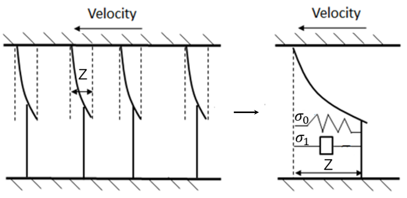
26] studied the dynamic behaviors of friction using a hydraulic cylinder. They proposed a modification to the LuGre model to improve the simulation accuracy. The LuGre friction model takes the surface contact as the bristles’ elastic deformation under the micro-structure as shown in
Figure 5. It can provide a comprehensive description of the static and dynamic characteristics of the friction between the piston and the cylinder. Whether the friction model parameters can be effectively and quickly identified from a large amount of experimental data is of great significance for improving the accuracy of the suspension model. This paper chooses the genetic algorithm (GA) to identify the friction model parameters because it has a comprehensive search range and is easy to obtain the optimal global solution.
The LuGre model is described by:
where
is the stiffness for a spring-like behavior for small displacements,
and
are the damping coefficient that relates to pre-sliding and viscous friction states,
z is the average bristle deflection,
is Stribeck’s curve in the function of sliding velocity,
is the Stribeck velocity,
and
are the static friction force and Coulomb force.
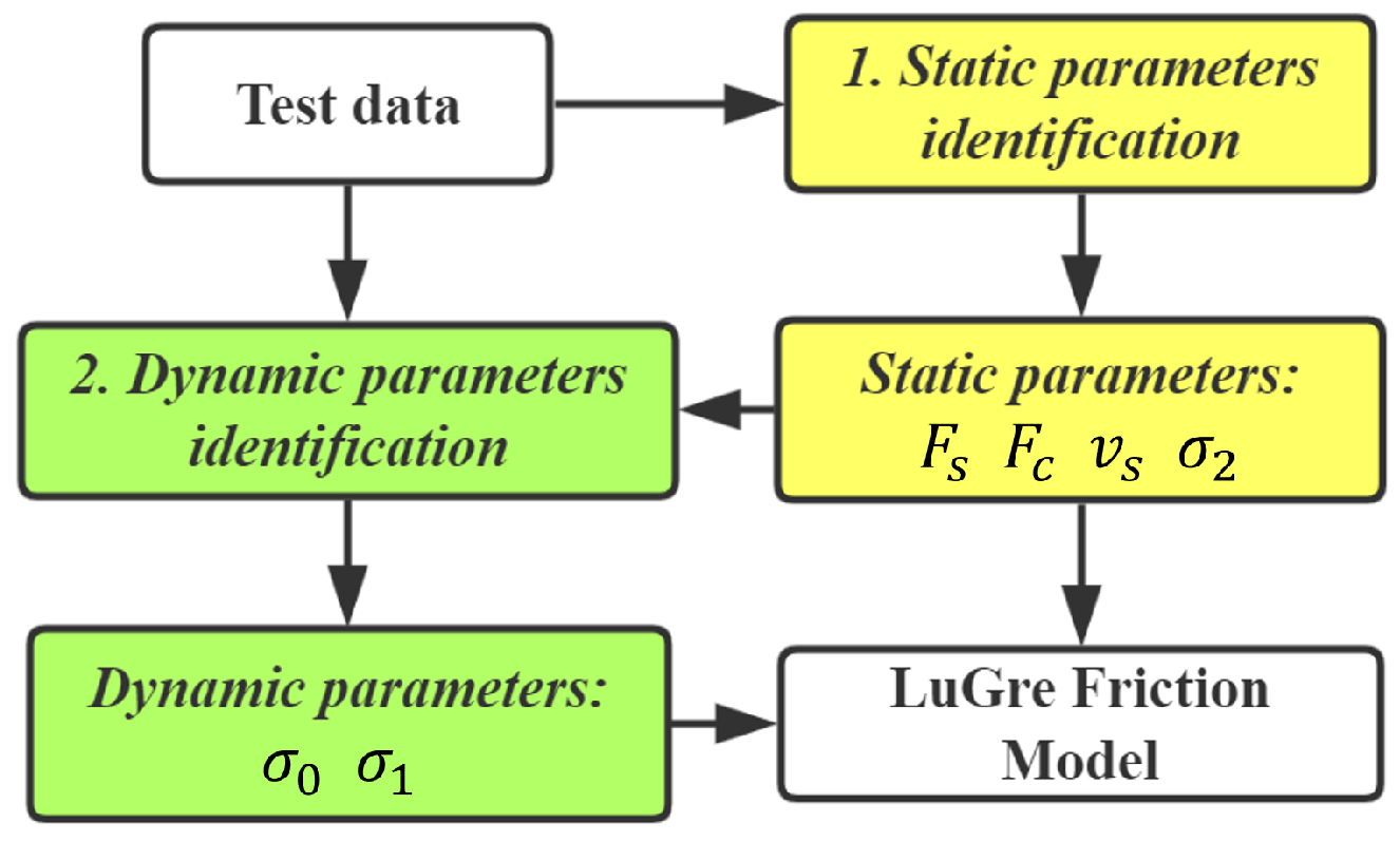
LuGre friction model includes four static parameters and two dynamic parameters. The GA program shown in
Figure 6 indicates the whole process of parameter identification. The first step is to identify the static parameters
,
,
and
. In the static case, it is assumed that the bristles’ deformation has reached the maximum and that is to say the
. In this step, the friction force can be expressed as:
The dynamic parameters identification is based on the static parameters result. Above four identified static parameters are brought into the Lugre friction model, and then the dynamic parameters
and
are also identified by the GA program.
In the Matlab GA program, the maximum generation is 200, the population size is 200, the reproduction ratio is
, and the mutation probability is
. The identified values of these parameters are shown in
Table 2.
4. Experimental Model Verification
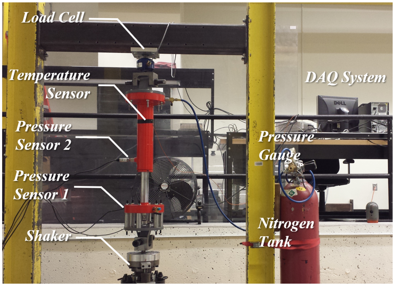
To validate the suspension model, the bench test of a single-cylinder hydropneumatic suspension shown in
Figure 7 is established. The parameters in
Table 1,
Table 2 and
Table 3 are used.
The top of the cylinder is fixed on a beam. Excitation is applied on the bottom of the piston by a shaker. A load cell is installed between the beam and cylinder. The pressure sensor 1 is installed on the bottom of the piston to measure gas pressure in chamber 1. The pressure sensor 2 is installed to measure the oil pressure in the hydraulic chamber. The shaker system has displacement and velocity sensors.
This test rig cannot test the friction force directly. Based on the data of load cell, the pressure in two chambers and displacement-velocity, friction force can be calculated accurately.
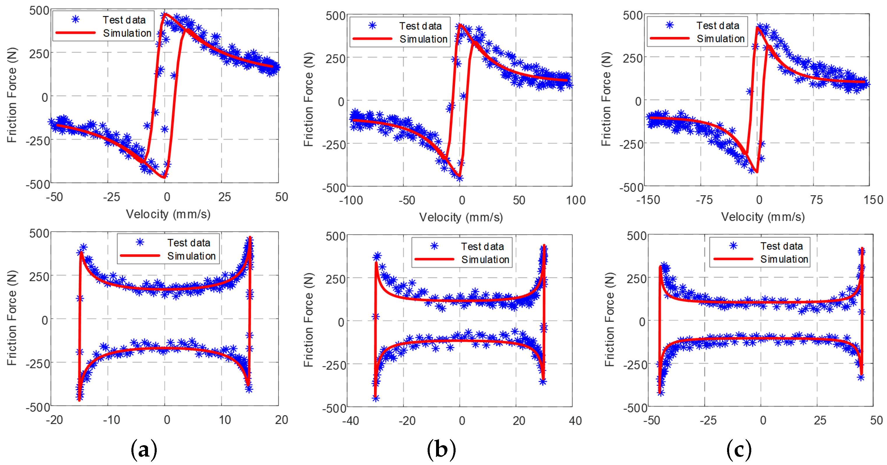
Figure 8 shows the test and model results of the friction force. The experimental data verifies the accuracy of the model of the hydropneumatic suspension.
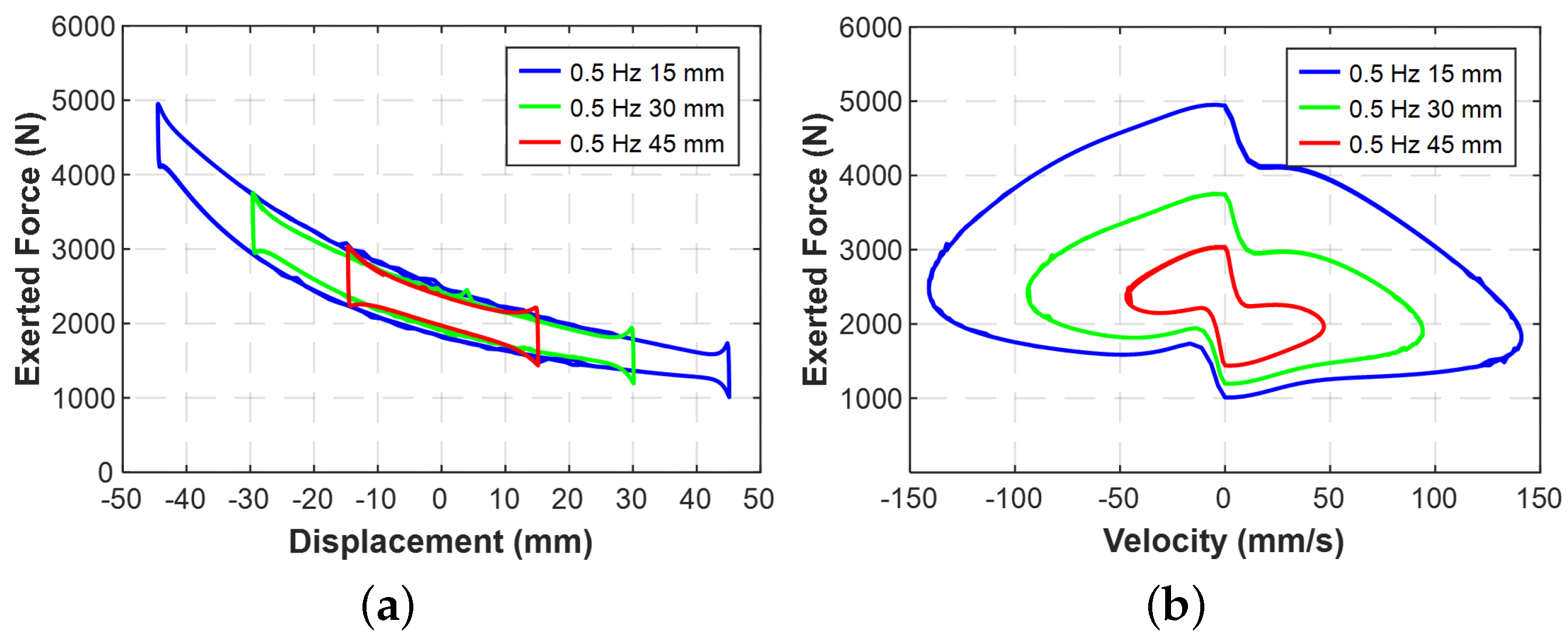
Figure 9 shows the exerted force of the hydropneumatic cylinder at 0.5 Hz with different amplitude harmonic vibration excitation. When the stroke is small, exerted force versus displacement has an approximate linear characteristic in
Figure 9a. However, with the stroke increasing, the exerted force shows power function characteristic. At the ends of each stroke in
Figure 9b, the non-linear characteristic of force discontinuity is caused by friction force direction changing.
6. Conclusions
This paper has introduced a whole set of hydropneumatic suspension system design for the tracked chassis of a road-rail vehicle that has to adapt to rugged and uneven road surface beside the railway. This hydropneumatic suspension system has been modelled and experimentally verified by the test rig data. One in-plane dynamics model integrated with this hydropneumatic suspension system are established. The influences of the diameter and length of the damping pipe and the initial gas volume on the vehicle ride performance have been analyzed with the systematic objective function.
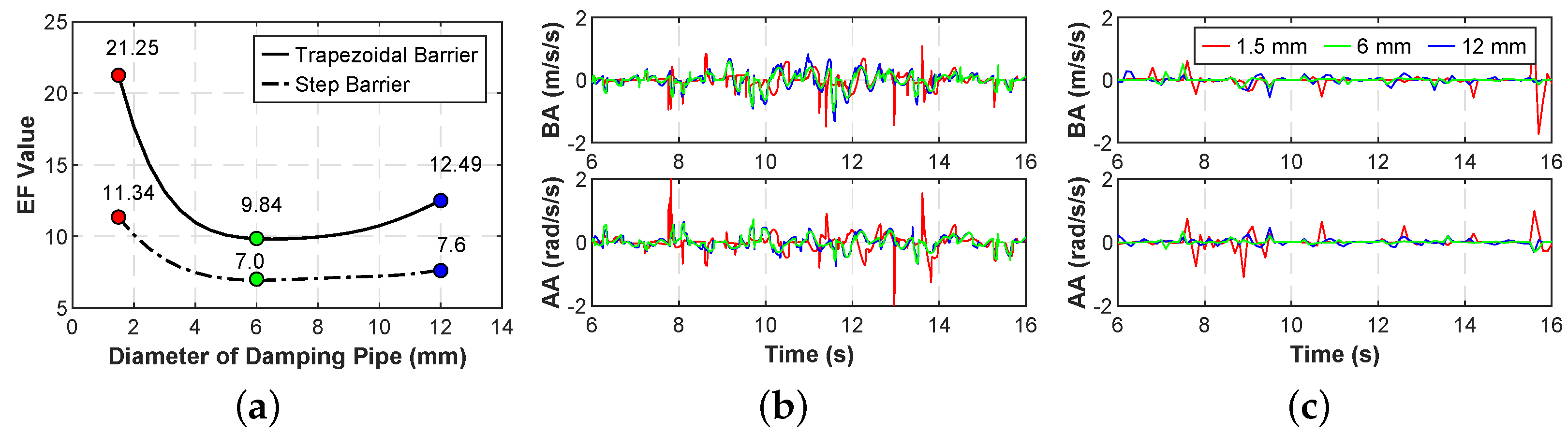
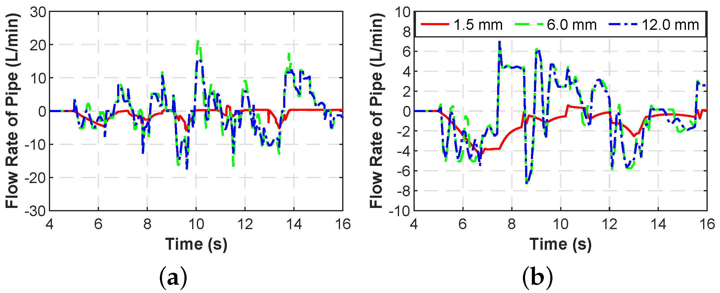
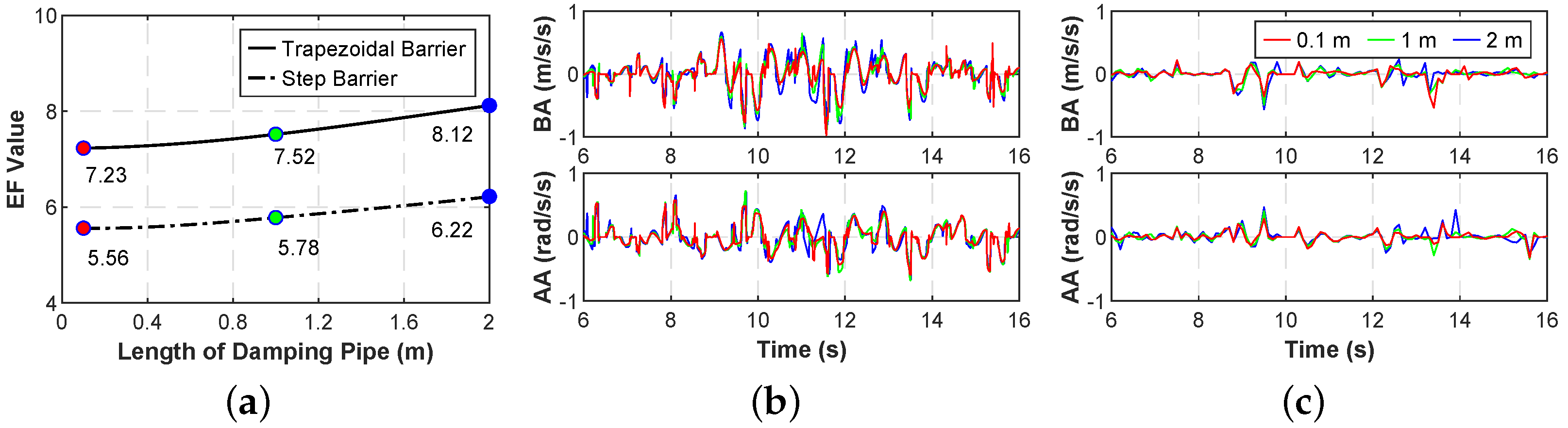
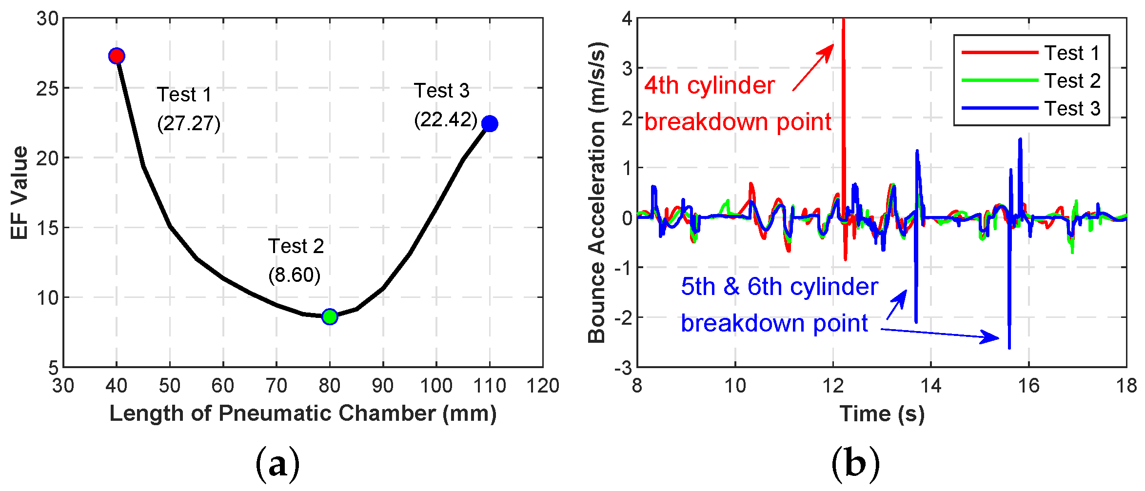
The test results indicate that the vehicle ride performance is remarkably improved by increasing the damping pipe diameter within a specific range. However, a continued increase in the diameter is not beneficial for further vibration attenuation. The damping pipe length has little effect on the ride performance of this vehicle, but there are still some adverse effects. Hence, the pipe length still needs to be minimized as much as possible. The insufficient gas volume will lead to a severe positive breakdown, especially on the central suspension cylinders, which will bear the entire body weight during the trapezoidal barrier traversing. Increasing the initial gas volume within a specific range can decrease the stiffness of the suspension and is conducive to the improvement of ride performance. However, it also brings the risk of negative breakdown at rear cylinders. That is mainly due to the vast compression of the front cylinders that will loosen the track at the rear. Hence, finding the optimal diameter of the damping pipe and the appropriate gas volume of the hydropneumatic cylinder could effectively enhance the ride performance and ensure vehicle stability and on-board equipment safety.
Based on this research, the next step research will focus on the force control of the tension cylinder, which is meaningful for the improvement of riding performance and reduce the possibility of the suspension breakdown phenomenon.


