Article

A Study on Liquid Leak Rates in Packing Seals

by
Abdel-Hakim Bouzid
Mechanical Engineering Department, École de Technologie Supérieure, Montreal, QC H3C 1K3, Canada
Appl. Sci. 2021, 11(4), 1936; https://doi.org/10.3390/app11041936
Submission received: 31 December 2020 / Revised: 17 February 2021 / Accepted: 19 February 2021 / Published: 23 February 2021
(This article belongs to the Section Mechanical Engineering)

Abstract

:
The accurate prediction of liquid leak rates in packing seals is an important step in the design of stuffing boxes, in order to comply with environmental protection laws and health and safety regulations regarding the release of toxic substances or fugitive emissions, such as those implemented by the Environmental Protection Agency (EPA) and the Technische Anleitung zur Reinhaltung der Luft (TA Luft). Most recent studies conducted on seals have concentrated on the prediction of gas flow, with little to no effort put toward predicting liquid flow. As a result, there is a need to simulate liquid flow through sealing materials in order to predict leakage into the outer boundary. Modelling of liquid flow through porous packing materials was addressed in this work. Characterization of their porous structure was determined to be a key parameter in the prediction of liquid flow through packing materials; the relationship between gland stress and leak rate was also acknowledged. The proposed methodology started by conducting experimental leak measurements with helium gas to characterize the number and size of capillaries. Liquid leak tests with water and kerosene were then conducted in order to validate the predictions. This study showed that liquid leak rates in packed stuffing boxes could be predicted with reasonable accuracy for low gland stresses. It was found that internal pressure and compression stress had an effect on leakage, as did the thickness change and the type of fluid. The measured leak rates were in the range of 0.062 to 5.7 mg/s for gases and 0.0013 and 5.5 mg/s for liquids.

1. Introduction

Valves of piping systems that use sealing devices (such as packed stuffing boxes) are prone to leakage failure, which may lead to the release of toxic substances that can cause environmental harm, health hazards, and loss of revenue. Advancements in the field of sealing technology have been overlooked because of the need to continuously develop new machinery to fulfill various demands in different industries. More emphasis has been placed on efforts to avoid catastrophic leak failure; little to no consideration has been given to minimizing leaks and reducing fugitive emissions [1]. From this standpoint, it was unrealistic to study the prediction of leak rates at micro/nano levels at a time when sealing was considered adequate if leakages were neither seen nor heard. Although some improvement has been observed in refineries that have implemented maintenance programs in accordance with revised standards on tightness procedures and tightening sequences (ASME PCC1) [2]—and provisions were made to better train pipe fitters—leakage is still a major issue in pressure vessels and the piping industry. However, with today’s focus on green consciousness and increasingly strict environmental regulations worldwide, achieving adequate tightness has taken on a different meaning [3,4]. In fact, leak rate is becoming a design criterion that has been implemented in standards such as EN and JIS and is under adoption by ASME BPVC. While zero-leak of pressurized equipment is a myth, the challenge for design engineers is to reduce leakage to a minimum. Few standard test procedures have been developed in recent years to certify valves [5,6,7], limit leakage failures, or reduce fugitive emissions [8], but there is a need to better understand fluid flow through sealing materials at the micro and nano levels in order to be able to predict leaks and improve tightness.
Over the past few decades, there has been some progress toward understanding the leakage behavior of packed stuffing boxes and bolted flange gasketed joints through analysis of the fluid flow through porous sealing materials. Analytical models have been developed to predict leaks [9,10,11,12,13]. However, the developed models are not representative of the true porous material behavior over the wide range of compressive loads, and thus have some limitations in their use. Some parameters to consider in any model development might include: the identification of the flow regime as a function of the applied load, the determination of the porosity parameters inherent to the sealing material, their variation in service, and the effect of the fluid type. A limited research work was published on liquid leak rates of porous gasket materials [14,15,16,17]. The difficulty of measuring small quantities of liquid leak (as compared to gas leak) has been scientifically recognized; there is no commercially available instrument that can directly measure liquid flow rates below 0.001 mL/s. Conversely, gas leaks are measured down to 10−8 mL/s with instruments based on spectrometry. For these reasons, most research has concentrated on the study of gas leaks. The researchers in [18,19] conducted tests with different gases to understand the behavior of porous gaskets and packing materials. Others predicted flow through porous media based on sophisticated modelling and simulations using the Monte Carlo method [20], with no practical use for gaskets and packing seals. The various existing analytical models and their experimental validations deal with the mass flowrate of liquids in a single capillary tube of known dimensions at room temperature. In addition, models described in the literature [21,22] treat gaseous flow in a capillary of a specific size and do not consider different-sized capillaries in order to cover macro- and nanoflows. Experimental studies conducted on packing seals with different gases at room temperature are reported in [23,24,25]. The current method used to correlate between different fluids (including liquids) is the simple viscosity ratio method, which is based on leaks conducted with a reference gas (usually helium). There are other more accurate methods that are based on porous structures, difficult to obtain for gaskets and packing seals under different operating conditions. Changes in the size and shape of the porous structure under load and temperature are difficult to measure in a test rig [26,27,28,29]. In addition, the prediction of leakage requires the operating conditions, flow regime and fluid properties to be known. The pressure, temperature, fluid density, dynamic viscosity, surface tension, and multiphase flow are to name a few.
In this study, an analytical model based on experimental determination of the porosity parameters used to accurately predict leak rates in packing seals under different operating conditions was proposed. The analytical model was based on fluid flow in capillaries, using the theory of Navier–Stokes, with the first slip boundary condition. The internal structure of the packing was simulated with rectilinear capillaries of unknown size and number, oriented in the stem axial direction. The objective was to predict liquid leak rates based on leakage measurements conducted on the same batch of packing seals under similar conditions, but with a reference gas (helium), from which the porosity parameters of the set of packing were deduced under isothermal steady-state conditions. In the last part of the study, liquid leaks at room temperature—measured experimentally—were compared to the predictions. A homemade liquid leak measuring device was developed to measure down to 0.0001 mL/s. Water and kerosene were selected for the experiments because they have different viscosities and are easy to manipulate.

2. Theoretical Model

The fluid flow in the packing rings was assumed to be in the stem axial direction. To simulate the flow through the porous material, a model consisting of several straight circular capillaries with a one-dimensional flow in each was considered—due to the axisymmetric flow assumption (as shown in Figure 1) for a packing seal.
The material was assumed to be made of N capillaries of radius R through which the fluid passed. The capillary r dependency of the flow is neglected because of the simplified consideration of the momentum correction factor. Therefore, the only dependency of the flow is the capillary axial z direction.
The correlation between velocity and pressure for a fully developed and isothermal flow in a capillary was obtained by the conservation of momentum equation:
1 r d d r   r d u d r = 1 μ d P d z
The maximum velocity was at the middle of tube such that:
d u ( r ) d r r = 0 = 0
The velocity at the wall, based on a first-order slip model of liquids, was
u ( r , z ) =   L s d u d r r = R
where Ls is the slip length with a liquid in a circular capillary and is given by [30]:
L s = 0.059 × γ 0.485   and   γ = Δ P R 2 μ
Integrating Equation (1) twice and applying the boundary conditions of Equations (2) and (3) gives the liquid velocity profile as a function of the pressure gradient in the z direction:
u ( r , z ) =   1 μ d P d z r 2 4 R 2 4 L s R 2
Integrating the velocity through the area of N capillaries gives the leak rate as:
L = N 0 R ρ 2 π r u r , z   d r
Substituting for u from Equation (5) into Equation (6) gives
L = N R 4 π   8   μ ρ d P d z 1 + 4 L s R
The total leak rate through the packing rings is independent of the length and therefore
0 L d z = P i P o N R 4 π   8   μ ρ 1 + 4 L s R d P
This gives the total liquid leak rate for N capillaries
L = N R 4 π ρ P i P o   8   μ 1 + 4 L s R
The porosity parameters N and R were obtained from a curve fitting of the measured data, obtained experimentally with helium gas. A similar theoretical approach for the flow through capillaries was applied—but for gases. Reference [15] gives the details on how to get the expression of the total leak rate for gas flow in packing rings given hereafter:
L g a s = N R 4 π P O 2 Π 2 1   16 T μ 1 + 2 σ σ 16 K n Π + 1
where Kn is the Knudsen number defined as:
K n = λ 2   R
Π is the pressure ratio given by:
Π =   P i P o
and λ is the mean free path given by:
λ =   16   μ   5   p o T 2   π
The equation of gas leak rate can be linearized in terms of the reciprocal pressure to give:
A = N R 4 1 + B 1 Π + 1
where
A = 16 μ T L g a s π P o 2 Π 2 1
and
B = 16 2 σ σ K n
σ is the tangential momentum accommodation coefficient, and is taken as 1. The porosity parameters N and R can be obtained from the slope A and intercept B from the curve fitted lines of the helium gas leak data as a function of the pressure ratio 1/(Π+1).

3. Experimental Testing

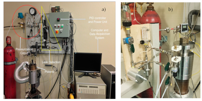
Leak tests with a set of four packing rings were conducted on the universal packing rig shown in Figure 2a. The rig had different modules to test stuffing box packing seals. The equipment was capable of performing gas and liquid tests at room and high temperatures. The test rig had three tubing systems, including a hydraulic tensioner tubing system that allowed the load to be applied to the gland through the stem using a hydraulic tensioner and a hand oil pump. The load on the packing rings was measured by means of a Wheatstone strain gauge bridge bound to the outside surface of the stem. A gas pressurization tubing system supplied pressure to the packed stuffing box using an air operated electronic valve and regulator connected to a 2400 psi gas bottle. Finally, an instrumented leak detection system for gas or liquids was connected to the packing rig leak collecting chamber to measure leaks. The universal packing rig was equipped with instruments to monitor pressure, gland stress, temperature, time, and leak rates, using a data acquisition and control system connected to a PC running a LabView interface program.
The packing test module shown in Figure 2b consisted of a housing, 104.8 mm (4.125 in.) in height, in which up to 7 packing rings of 9.5 mm (3/8 in.) could be inserted in square section. The axial displacement of the packing rings due to compression was measured by two Linear Variable Differential Transducers, LVDTs placed diametrically opposed. The rig was equipped with five different leak measurement systems (based on different techniques) to be used depending on the level of leak rate that needed to be measured. These were: flow meter, pressure decay, pressurized rise, and mass spectrometry, to cover a leak range from 10 to 10−10 mL/s for gases. A liquid leak measurement device that could measure leaks ranging from 1 to 0.00001 mL/s was also included. In this study, only the flowmeter and the pressure rise methods were used to measure helium leak rates and characterize the porous structure. The test module shown in Figure 2b was specially designed to include a central hollow cylinder inserted inside the housing between the packing and the stem. This created a tight chamber, so that the packing rings could be installed in the stuffing box inside a bucket filled with the test liquid to keep air bubbles from getting trapped in the system. The packing dimensions were 57 mm (2.25 in.) in outside diameter and 38 mm (1.5 in.) in inside diameter. The stem was made of SA193 B7 material with a diameter of 28.6 mm (1.125 in.).
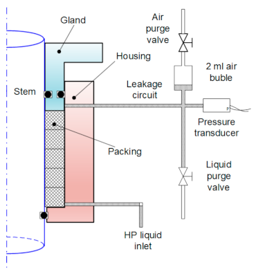
The special liquid leak measuring device shown in Figure 3 was used successfully in [15]—and was used here to measure leaks down to 10−5 mg/s of water. The outside leak collection chamber was also filled with the same liquid, allowing only a 2 mL volume of air to be compressed during leak measurements. Any leak into the collecting chamber compressed the small air volume and increased its pressure. The liquid leak measuring device was composed of a liquid supply and purge system to operate safely and protect the 2 psi pressure transducer.
The gland stresses, ranging from 10.34 to 24.14 MPa, were applied to the set of packing rings through the hydraulic tensioner fixed to the stem. For every level of gland stress, helium gas or liquid pressures ranging from 0.34 to 2.76 MPa were applied in steps, and the leak rate was measured. Additionally, the experimental samples were braided flexible graphite packing and graphite die rings. All tubes of pressurization and the leak detection system were thermally isolated to avoid the influence of temperature variations on pressure and therefore on the leak measurements.

4. Results and Discussion

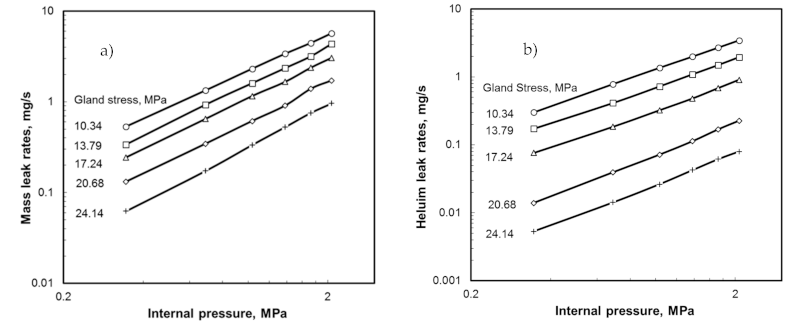
The porosity parameters were determined using tests with a reference gas; in this case, helium. Helium was selected because it is the smallest safe particle, but nitrogen could also have been used. Figure 4a,b shows the results of the gas leak tests for the flexible graphite and die ring seals, respectively. It is to be noted that the relationship between leak and pressure for the different gland stresses was rather linear in a log-log scale, because the laminar flow was predominant under the testing conditions with helium. Indeed, this is confirmed by the first term of Equation (10).
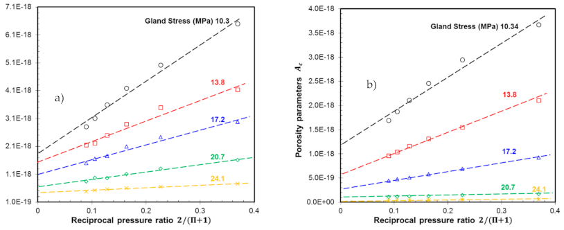
Figure 5a,b shows the relationship between the porosity parameter A, given by Equation (14), and the reciprocal pressure Π for the braided flexible graphite and graphite die rings, respectively. From the linear behavior observed in the curves obtained at the different gland stress levels, the two porosity parameters (the number and diameter of the capillary, N and R) were determined using Equations (15) and (16). The intercept of line A gives NR4, as per Equation (12), whereas the slope gives BNR4, and hence B was obtained. The Knudsen number was then obtained from Equation (16) for σ equal to 1, from which the hydraulic diameter D = 2R was deduced for the specific gas used for the characterization test. Finally, the number of capillaries N was obtained.
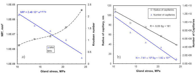
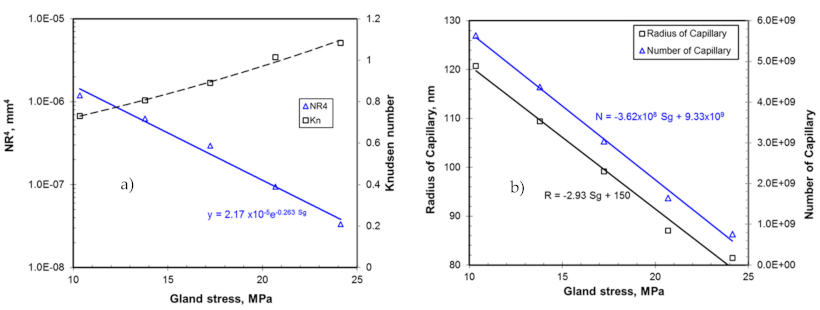
Figure 6a and Figure 7a show the variations of the porosity parameter NR4 and Knudsen number with the gland stress. The porosity parameter was exponentially decaying with stress and the Knudsen number was below 2.5, which indicates a transitional flow regime. Figure 6b and Figure 7b show the variation of the radius and number of capillaries as a function of the gland stress. Using these curves, the capillary size and number under any specific packing stress were obtained, in order to predict the leak rate of the liquid under consideration using Equation (8). While the relationship between NR4 and stress was exponential, the relationship became linear when the two parameters, N and R, were taken individually. The linear relationships were obtained by a curve fit for both materials. It is to be noted that both parameters decreased with a gland stress increase. The graphite die rings had a comparatively lower radius and a lower number of capillaries.
The relationships for the braided flexible graphite packing were:
R = 5.05 × S g + 161 N = 7.61 × 10 8 S g + 1.92 × 10 10
Likewise, for the graphite die rings:
R = 2.93 × S g + 150 N = 3.62 × 10 8 S g + 9.33 × 10 9
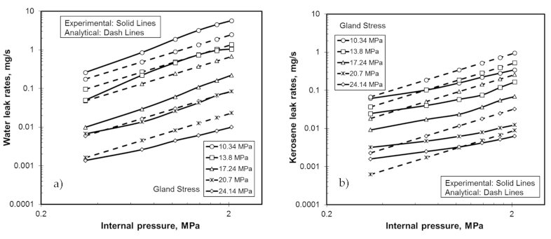
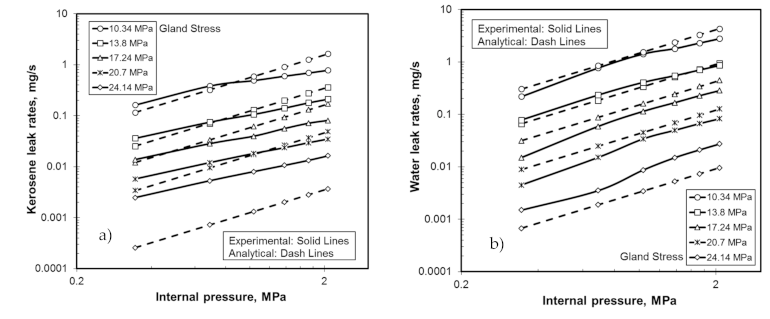
From this relationship, the extrapolated lines gave a radius of 161 nm and 150 nm, respectively, for the braided flexible graphite packing and graphite die rings, at no stress or as received. Capillaries numbered at 1.92 × 10¹⁰ and 9.33 × 10⁹ for these two materials, respectively. Equations (17) and (18) were used—in conjunction with kerosene and water properties and Equation (14)—to predict leak rates through these two materials. Parallel experimental tests were conducted with these two liquids on both materials under the gland stresses and pressures given above. The comparisons are shown in Figure 8 and Figure 9. The predictions for both materials were within acceptable limits at low stress. However, the model was less accurate, showing a considerable difference from the experimental measurements, especially for high gland stresses. The difference depended on the applied liquid pressure and the level of the gland stress. Nevertheless, the predictions were considered acceptable, since the level of liquid leak was small. There are a few factors that could explain the difference in results between the analytical model and the experimental data. First, there are two types of leaks: interfacial and porous leaks. The proportion of interfacial leak to porous leak at low stress is different for gases and liquids. Second, the slip length, taken for reference [26] for gaskets, may not be suitable for packing rings. Indeed, surface tensions present with liquids may be dependent on the material being used. Finally, the material variation between one packing ring and another may have played a role, since the set of packing rings used to characterize the porosity parameters was different every time a fluid was changed. In fact, the gas leak tests (conducted for porosity characterization) and liquid leak tests were conducted with different packing sets.

5. Conclusions

An analytical methodology to predict the leak rates for incompressible fluids was developed. The pseudo experimental-analytical approach was used to determine porosity parameters from experimental tests conducted with helium. This model was then applied to the model-derived formulation to predict liquid leakage. The model was based on a number of straight capillaries of the same diameter, to which the liquid slip flow condition was applied. Although some satisfaction was obtained with the predictions during their comparison with the test data, the water and kerosene results (conducted on braided flexible graphite packing and graphite die rings) showed less accuracy, especially at high stress levels. Surface tension, slip length, interfacial leak paths, and material variability are all suspected causal factors. The leak measuring device could also have played a role in the different data obtained. This homemade device cannot detect leaks below ±0.00001 mg/s. The difference was as high as 100% at high stress levels. Nevertheless, at very small leak detection levels, this difference is to be expected. This work can be extended to include other packing materials and fluid media. The reduction of liquid leak rates due to increased viscosity, surface tension, and temperature is worth investigating.

Author Contributions

Conceptualization, A.-H.B.; methodology, A.-H.B.; formal analysis, A.-H.B.; investigation A.-H.B.; writing—review and editing, A.-H.B. All authors have read and agreed to the published version of the manuscript.

Funding

This research received no external funding.

Institutional Review Board Statement

Not applicable.

Informed Consent Statement

Not applicable.

Acknowledgments

The author is very grateful to Aweimer A.S.O. for the valuable assistance provided in the experimental tests performed for this work.

Conflicts of Interest

The author declare no conflict of interest.

Nomenclature

KLateral pressure coefficient
KnKnudsen number
LLeak rate, kg/s
Total axial length of packing rings, m
LsSlip flow in liquids, µm
NNumber of capillaries
NR4Porosity Parameters for tapered capillary, m4
PPressure, Pa
RPore radius at distance z, m
RRadial direction, m
TTemperature, K
UAxial velocity, m/s
ZCapillary axial direction, m
Greek Letters
λMean free path, m
μDynamic viscosity, Pa s
ρDensity, kg/m³
σTangential momentum accommodation coefficient
ΠInlet to outlet pressure ratio
Specific gas constant, J/kg K
ΔPPressure difference between upstream and downstream, Pa
Subscripts or Superscripts
IInlet or upstream
OOutlet or downstream

References

  1. Chambers, A.K.; Strosher, M.; Wootton, T.; Moncrieff, J.; McCready, P. Direct Measurement of Fugitive Emissions of Hydrocarbons from a Refinery. J. Air Waste Manag. Assoc. 2008, 58, 1047–1056. [Google Scholar] [CrossRef] [PubMed]
  2. ASME PCC1. Guidelines for Pressure Boundary Bolted Flange Joint Assembly; American Society of Mechanical Engineers: New York, NY, USA, 2010. [Google Scholar]
  3. Shabtai, A.; Elovici, Y.; Rokach, L. A Survey of Data Leakage Detection and Prevention Solutions; Springer: New York, NY, USA, 2012. [Google Scholar]
  4. Payne, J.R. PVRC Flanged Joint User Survey. Weld. Res. Counc. 1985, 306, 1–45. [Google Scholar]
  5. American Petroleum Industries. API-622—Type Testing of Process Valve Packing for Fugitive Emissions; API Publishing Services: Washington, DC, USA, 2018. [Google Scholar]
  6. American Petroleum Industries. API-624—Type Testing of Rising Stem Valves Equipped with Flexible Graphite Packing for Fugitive Emissions; API Publishing Services: Washington, DC, USA, 2014. [Google Scholar]
  7. International Standard Organization. ISO-15848—Industrial Valves—Measurement, Test and Qualification Procedures for Fugitive Emissions; ISO: Geneva, Switzerland, 2015. [Google Scholar]
  8. Bayreuther, D. Fugitive Emission Testing and Certification of Valves: What Next? Valve Manufacturers Association of America. 2016. Available online: https://www.valvemagazine.com/web-only/categories/technical-topics/7476-fugitive-emission-testing-and-certification-of-valves-what-next.html (accessed on 12 October 2020).
  9. Ergun, S. Fluid Flow through Packed Columns. Chem. Eng. Prog. 1952, 48, 89–94. [Google Scholar]
  10. Macdonald, I.; El-Sayed, M.; Mow, K.; Dullien, F. Flow through Porous Media—The Ergun Equation Revisited. Ind. Eng. Chem. Fundam. 1979, 18, 199–208. [Google Scholar] [CrossRef]
  11. Masi, V.; Bouzid, A.; Derenne, M. Correlation between Gases and Mass Leak Rate of Gasketing Materials. In Proceedings of the 1998 ASME/JSME Joint Pressure Vessels and Piping Conference, San Diego, CA, USA, 26–30 July 1998; Volume 367, pp. 17–24. [Google Scholar]
  12. Beskok, A.K. Report: A Model for Flows in Channels, Pipes, and Ducts at Micro and Nano Scales. Microscale. Eng. 1999, 3, 43–77. [Google Scholar]
  13. Xue, H.; Fan, Q.; Shu, C. Prediction of Micro-Channel Flows Using Direct Simulation Monte Carlo. Probabilistic Eng. Mech. 2000, 15, 213–219. [Google Scholar] [CrossRef]
  14. Asahina, M. Estimation of Sealability with Compressed Fibers Sheet Gaskets for Liquid and Gas Fluid. In Proceedings of the 1998 ASME/JSME Joint Pressure Vessels and Piping Conference, San Diego, CA, USA, 26–30 July 1998; Volume 367, pp. 25–34. [Google Scholar]
  15. Grine, L.; Bouzid, A. Liquid Leak Predictions in Micro-and Nanoporous Gaskets. ASME J. Press. Vessel. Technol. 2011, 133, 051402-(6). [Google Scholar] [CrossRef]
  16. Hsieh, S.S.; Lin, C.Y.; Huang, C.F.; Tsai, H. Liquid Flow in a Micro-Channel. J. Micromech. Microeng. 2004, 14, 436–446. [Google Scholar] [CrossRef]
  17. Koo, J.; Kleinstreuer, C. Liquid Flow in Microchannels: Experimental Observations and Computational Analyses of Microfluidics Effects. J. Micromech. Microeng. 2003, 13, 568–579. [Google Scholar] [CrossRef]
  18. Marchand, L.; Derenne, M.; Masi, V. Predicting Gasket Leak Rates Using a Laminar-Molecular Flow Model. In Proceedings of the ASME Pressure Vessels and Piping Conference–2005, Denver, CO, USA, 17–21 July 2005; pp. 87–96. [Google Scholar]
  19. Grine, L.; Bouzid, A. Correlation of Gaseous Mass Leak Rates through Micro-and Nanoporous Gaskets. ASME J. Press. Vessel. Technol. 2011, 133, 021402-(6). [Google Scholar] [CrossRef]
  20. Sbragaglia, M.; Succi, S. Analytical Calculation of Slip Flow in Lattice Boltzmann Models with Kinetic Boundary Conditions. Phys. Fluids 2005, 17, 093602. [Google Scholar] [CrossRef]
  21. Dongari, N.; Agrawal, A.; Agrawal, A. Analytical Solution of Gaseous Slip Flow in Long Microchannels. Int. J. Heat Mass Transf. 2007, 50, 3411–3421. [Google Scholar] [CrossRef]
  22. Maurer, J.; Tabeling, P.; Joseph, P.; Willaime, H. Second-Order Slip Laws in Microchannels for Helium and Nitrogen. Phys. Fluids 2003, 15, 2613–2621. [Google Scholar] [CrossRef]
  23. Diany, M.; Bouzid, A.H. An Experimental-Numerical Procedure for Stuffing Box Packing Characterization and Leak Tests. J. Tribol. 2011, 133, 012201-(8). [Google Scholar] [CrossRef]
  24. Kazeminia, M.; Bouzid, A. Leak Prediction through Porous Compressed Packing Rings: A Comparison Study. Int. J. Press. Vessel. Pip. 2018, 166, 1–8. [Google Scholar] [CrossRef]
  25. Aweimer, A.S.O.; Bouzid, A. Evaluation of Interfacial and Permeation Leaks in Gaskets and Compression Packing. J. Nucl. Eng. Radiat. Sci. 2019, 5, 011013-(9). [Google Scholar] [CrossRef]
  26. Diany, M.; Bouzid, A. Analytical Evaluation of Stresses and Displacements of Stuffing-Box Packing Based on a Flexibility Analysis. Tribol. Int. 2009, 42, 980–986. [Google Scholar] [CrossRef]
  27. Ochonski, W. Radial Stress Distribution and Friction Forces in a Soft-Packed Stuffing-Box Seal. Tribol. Int. 1988, 21, 31–38. [Google Scholar] [CrossRef]
  28. Pengyun, S.; Kuangmin, C.; Zongyun, D. Theoretical Analysis of the Lateral Pressure Coefficients in a Soft-Packed Stuffing-Box Seal. Tribol. Int. 1997, 30, 759–765. [Google Scholar] [CrossRef]
  29. Hoa, X.J.; Saulot, A.; Busquet, M.; Berthier, Y.; Torrance, A.A.; Hersant, D. Tribological investigation of packing friction along the stem of a valve. Tribol. Int. 2013, 65, 354–362. [Google Scholar] [CrossRef]
  30. Choi, C.H.; Westin, K.J.A.; Breuer, K.S. Apparent Slip Flows in Hydrophilic and Hydrophobic Microchannels. J. Phys. Fluids 2003, 15, 2897–2902. [Google Scholar] [CrossRef]
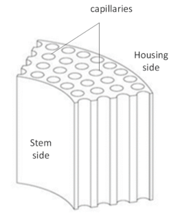
Figure 1. Capillary tubes in a simulated packing seal.
Applsci 11 01936 g001
Figure 2. Universal packing test rig: (a) gas test module and (b) liquid test module.
Applsci 11 01936 g002
Figure 3. Liquid leak measuring device for packing rig.
Applsci 11 01936 g003
Figure 4. Helium leak tests (a) Flexible graphite, (b) die ring.
Applsci 11 01936 g004
Figure 5. Graphs to obtain porosity parameters. (a) Flexible graphite, (b) die ring.
Applsci 11 01936 g005
Figure 6. Variation of porosity parameters and Knudsen number for of Flexible graphite.
Applsci 11 01936 g006
Figure 7. Variation of porosity parameters and Knudsen number for die rings.
Applsci 11 01936 g007
Figure 8. Leak rate predictions in flexible graphite packing (a) water (b) kerosene.
Applsci 11 01936 g008
Figure 9. Leak rate predictions in die rings (a) water (b) kerosene.
Applsci 11 01936 g009
Publisher’s Note: MDPI stays neutral with regard to jurisdictional claims in published maps and institutional affiliations.