Article

Wheeler Method for Evaluation of Antennas Submerged in Lossy Media

Department of Electrical Engineering, Pohang University of Science and Technology, Pohang 37673, Korea
*
Author to whom correspondence should be addressed.
Appl. Sci. 2021, 11(4), 1862; https://doi.org/10.3390/app11041862
Submission received: 18 January 2021 / Revised: 10 February 2021 / Accepted: 18 February 2021 / Published: 20 February 2021

Abstract

:
A Wheeler method for the evaluation of the radiation efficiency of submerged antennas within lossy media is presented and demonstrated for the first time in the literature. Extensive investigations have been devised by empirical and simulation methods. Normal-mode helical antenna (NMHA) was first designed and fabricated to exemplify a real-life application at the UHF band (0.3 to 3 GHz). The antenna under test (AUT) was evaluated within an artificial lossy material using a series of Wheeler caps featuring different radii to study the validity of this method. The error between the experimental and simulation radiation efficiency is below 3% near the theoretical radian length. The presented measurement method of radiation efficiency without any essential measurement facilities or accessories could be a promising candidate for fast and accurate evaluation for any wire-type antenna submerged within lossy media.

1. Introduction

Antenna radiation efficiency is an important parameter for calculating the wireless link budget and optimizing antenna structures. This can be controlled and improved by modifying the antenna topology in the case of the constant antenna volume [1,2,3,4]. Currently, various methods such as pattern integration method, the Wheeler method [5,6,7,8], radiometric method [9], and the Q–factor method [10] have been reported for measuring radiation efficiency in free-space.
For some applications, such as in underwater, underground, and in-body scenarios, wireless signals propagate through lossy media [11,12,13,14,15]. These usually have short-range communication systems due to the high attenuation of electromagnetic (EM) waves in the lossy medium. Meanwhile, the antenna characteristics are significantly different from those in free space. In this respect, antennas submerged in lossy media has been analytically and numerically studied using ideal dipole antennas. These studies include modified parameters such as radiation efficiency, directivity, gain and effective area [16,17], and the effects of the insulation layer of submerged antennas and the equivalent circuit model of uninsulated antenna [18,19].
Since the conventional radiation efficiency [20] is only useful for lossless media, studies of radiation efficiency in lossy media have been in demand. The radiation characteristics of submerged antennas in lossy media have been mostly measured using the gain comparison method which employs standard gain reference antennas [21,22,23,24]. The recently reported measurement technology using a reverberation chamber was conducted to measure the radiation efficiency in consideration of the spurious radiation effect of the feed cable [25]. However, the attenuation area is different depending on the conditions of the lossy medium, such as shape, size, and antenna location [21]. In addition, it is difficult to apply this approach for applications such as establishing a wireless link between implanted devices. To resolve these drawbacks, a modified radiation efficiency is introduced based on the total power of the radiated field through the spherical surface with a radius of propagation distance [16,17,26,27]. However, the modified radiation efficiency method still exhibits an inverse proportion between measurement data accuracy and testing time to obtain total radiated power in all spherical surfaces.
This paper introduces and demonstrates an efficient evaluation method for the radiation efficiency of submerged antennas in lossy media by using the Wheeler method. Without the required measurement facilities or essential accessories to obtain electric field intensity or power density, the presented Wheeler cap method has been devised featuring a short testing time and high accuracy using only the Wheeler metallic cavity. This paper is organized as follows: Section 2 introduces the antenna radiation efficiency for lossy media; in Section 3, the evaluation method of radiation efficiency in media with various dielectric constant and loss tangent has been demonstrated by using the Wheeler method, and the measured efficiency of a wire antenna within the artificial lossy material [28] at the UHF band (0.3 to 3 GHz) is concluded to be in good agreement with the measured efficiencies; Section 4 concludes the paper.

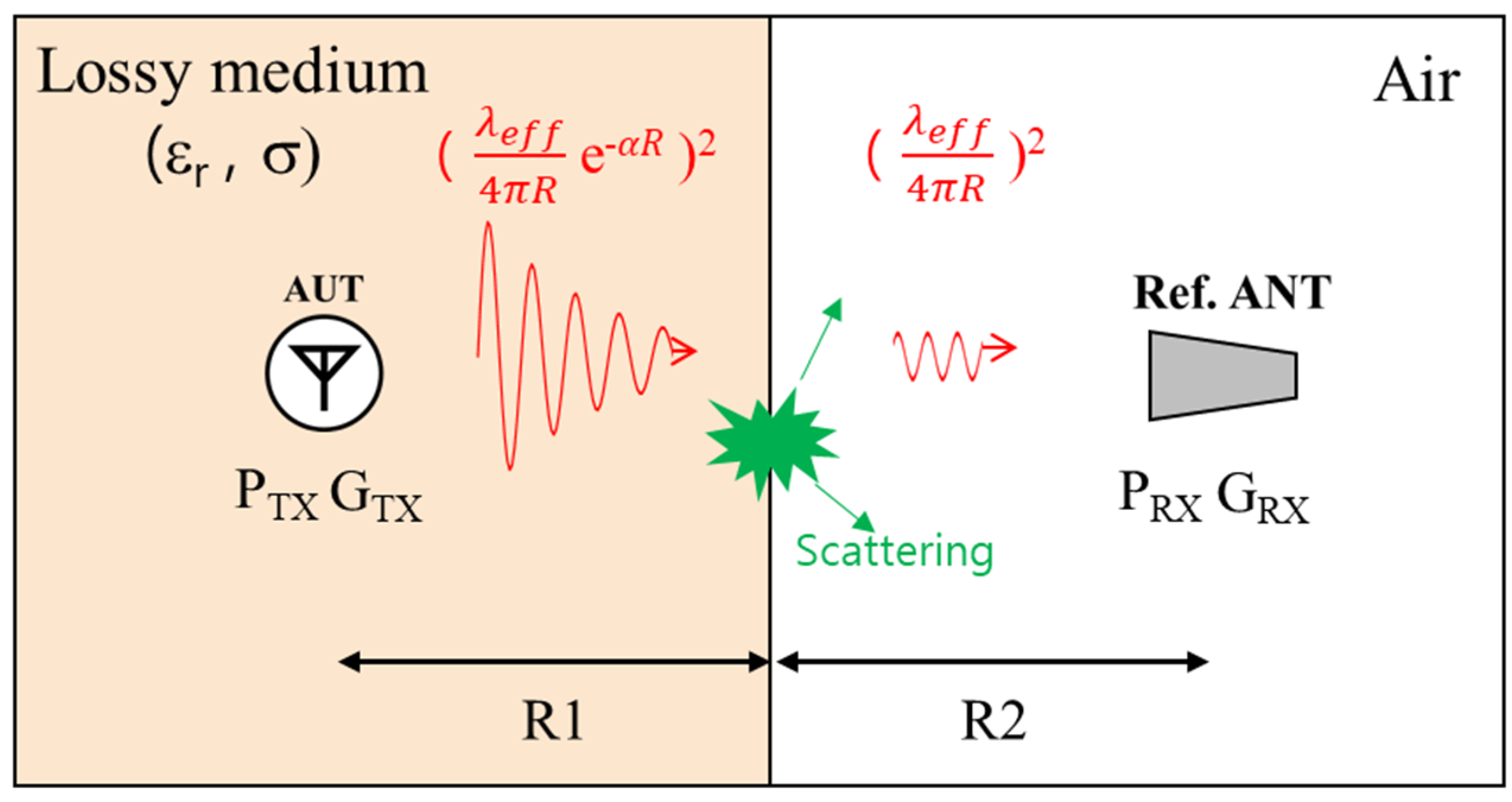
2. Antenna Radiation Efficiency for Lossy Media

Measurement using the gain comparison method in lossy media is presented in Figure 1. The propagation region between Tx and Rx is divided into two physical layers: lossy medium and air. Inevitably, the radiated field is scattered at the boundary. Attenuation region R1 is different depending on the conditions of the lossy medium such as shape, size, and antenna location. In this case, the radiation efficiency based on combining radiated power in all directions cannot be specified [21].
A modified radiation efficiency η M R of the antenna for lossy media is defined as follows:
η M R ( d r ) = P r a d ( d r ) / P a c c = P r a d ( d r ) / ( P i n ( 1 | S 11 | 2 ) ) ,
where P r a d is the total radiated power related to the propagation distance due to the path loss in the lossy media (Figure 2), P i n is the incident power, and P r a d is the power incident to the antenna terminals. It is calculated by integrating the power flow normal to the virtual sphere surface according to the radial distance from the antenna center [4]. However, all previously reported works related to the modified radiation efficiency have been demonstrated and verified without experimental results [16,17,26,27].
The Wheeler method is used to assess the efficiency η M R of the insulated antenna in lossy media (Figure 3a). When d r is equal to the radius of the Wheeler cap, the modified radiation efficiency can be briefly obtained using the Wheeler method. When the metallic cap with a radius of radian length is covered, the radiation resistance can be removed with an equivalent circuit, as shown in Figure 3b. The radiation efficiency η W R is obtained as follows:
η W R = R e { Z i n } R e { Z W C } R e { Z i n } ,
where Z i n is the antenna input impedance, Z W C is the input impedance by enclosing the antenna with a radiation shield [8]. The radius of the radiation shield is equal to the radian length, where the far-field and near-field have the same intensity. The radian length r l in free space is as follows:
r l = λ g   2 π = λ 0 2 π ε r ,
where λ 0 is the wavelength in a vacuum, λ g is the wavelength in the media. In lossy media, the radian length r l can be calculated as follows:
r l = 1 { ( ε μ ω 2 ) 2 + ( ω μ σ ) 2 } 0.25 ,
where ε is the permittivity, μ is the permeability, σ is the conductivity, ω is the angular frequency.

3. Analysis of the Wheeler Cap Method of Antenna Surrounded by the Lossy Media

3.1. Simulation

3.1.1. Simulation Setup

The radiation efficiency evaluation method is validated by stepwise analysis according to the change in the dielectric constant and conductivity of the medium encompassing the antenna. The radiation efficiency analysis using the Wheeler method is conducted through ANSYS HFSS. A normal-mode helical antenna (NMHA) resonating at a frequency of 172 MHz in air and an insulation layer are designed using copper wire and Teflon ( ε r   = 2.1, tan δ   = 0.001), respectively. The detailed dimensions of the antenna are illustrated (Figure 4a). The metallic cavity is designed as a hemisphere consisting of PEC (Figure 4b). The space inside the insulation layer is modeled as air and remained identical across all experiments. The simulation setup is presented in Figure 4c. The size of the lossy medium is 1000 mm × 1000 mm × 500 mm.

3.1.2. Radiation Efficiency in Media with Dielectric Constant

The radiation efficiency is analyzed for a medium with a high dielectric constant in a lossless state. In this scenario, only the dielectric constant of the material is controlled. The results are sampled at a single frequency at which a resonance occurs at each medium. The cavity length r w is expressed as a ratio of length-to-wavelength.
The efficiency η W R calculated according to the metallic cavity radius r w is compared with the efficiency η M R calculated based on the field computation (Figure 2). The radiation resistance can be extracted using a radiation shield with a radius equal to the radian length. The comparison shows that the same radiation efficiency can be obtained when the cavity radius r w is equal to the radian length r l for each medium (Figure 5). This ascertains that the Wheeler method is applicable even for media featuring a dielectric constant other than 1. The radiation efficiency is maintained over the radian length range.

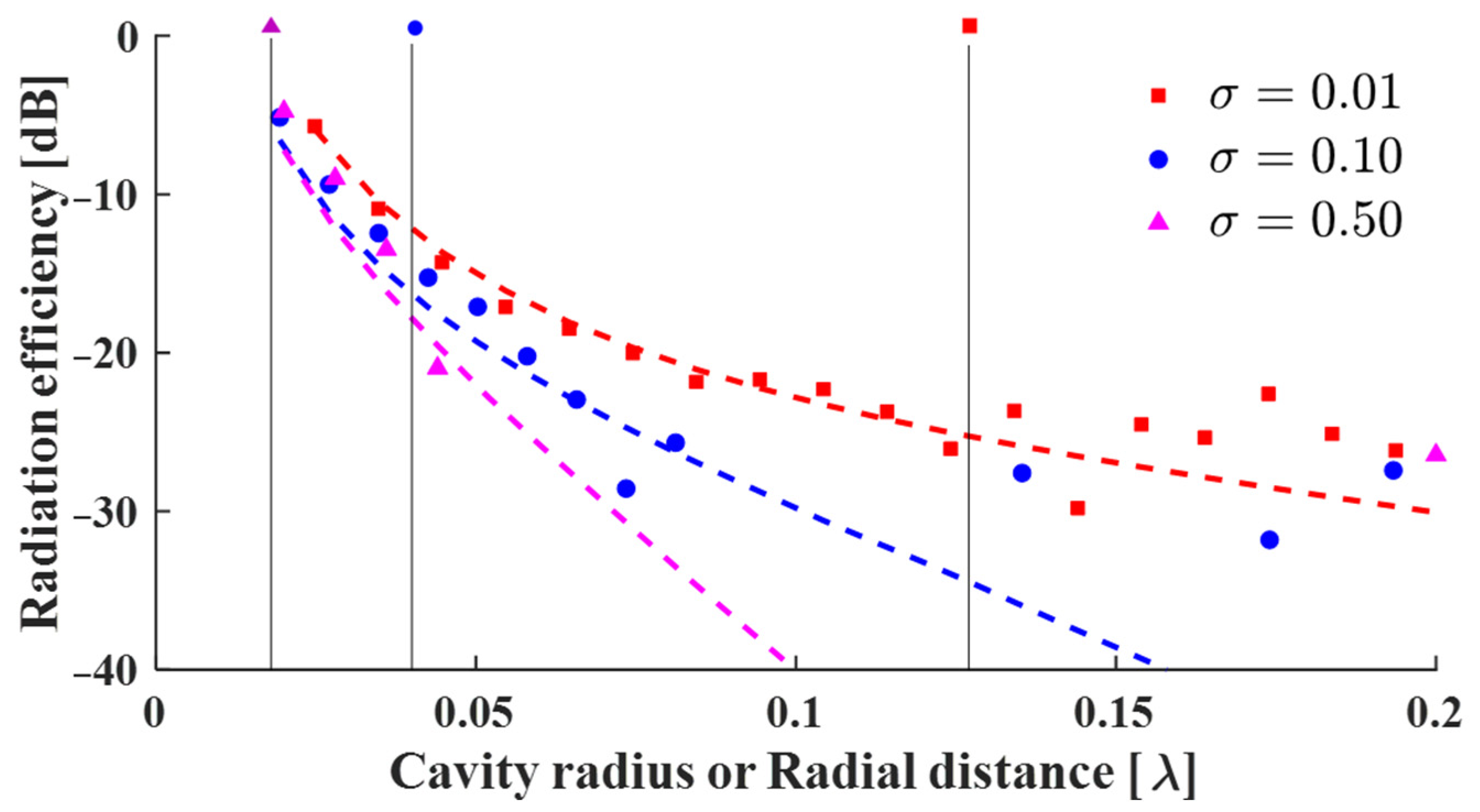
3.1.3. Radiation Efficiency in Lossy Media

The dielectric constant of the material is fixed at 1 and the conductivity is set as a variable. The results are sampled at a single frequency at which resonance occurs at each medium. The efficiency η W R calculated according to the metallic cavity radius r w is compared with the efficiency η M R calculated based on the field computation (Figure 2). As mentioned above, η M R can obtain the uniform radiation efficiency in lossless media (Figure 5), but it cannot be applicable in lossy media. As radial distance d r increases, the propagation loss increases and the radiation efficiency η M R decreases rapidly (Figure 6).
When the conductivity is as low as 0.01 S/m, the efficiency η W R is almost similar to the radiation efficiency η M R calculated by the field calculator (Figure 2) in a short propagation distance range. Additionally, the radiation efficiency of η W R and η M R show good agreement when the cavity radius r w is equal to the radian length r l of each medium. This clearly confirms that the Wheeler method can be applicable to lossy media.
However, when the conductivity is relatively high, the error is significantly increased as r w becomes larger than the radian length r l . The coupling resistance between the antenna and the cavity mode of the radiation shield causes errors in the efficiency measurement [29,30]. When the cavity resonator is filled with lossy material, the quality factor is lowered [31]. Therefore, the increased Z W C due to the cavity mode causes errors over a wide range. A radiation shield should be selected in an appropriate shape.

3.2. Measurement

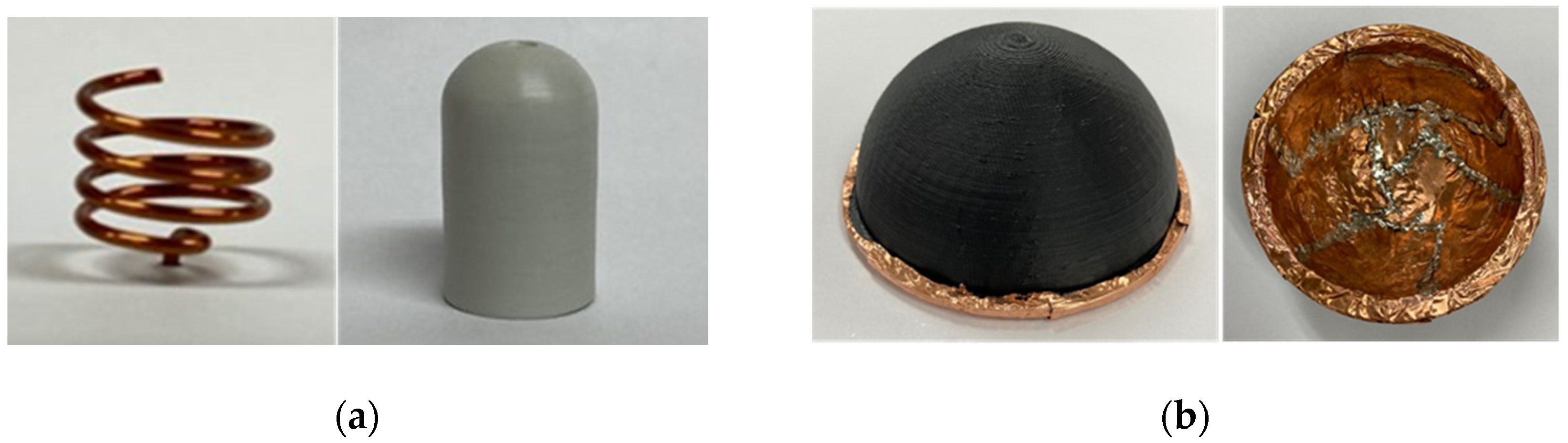
3.2.1. Measurement Setup

A UHF band antenna was devised and the radiation efficiency was measured when the antenna was submerged within an artificial lossy material. The detailed measurement setup is introduced in Figure 7 and Figure 8. The AUT was made of NMHA type and was blocked from the medium by a capsule-shaped polyimide ( ε r   = 3.5, tan δ   = 0.008) insulation layer (Figure 7a). Antenna in the UHF band within the lossy medium are described in Table 1. Radiation shields with three radii (20, 30, 70. Unit: mm) were designed for demonstration. It was fabricated by covering a copper sheet on a hemisphere model using a 3D printing methodology (Figure 7b).
The overall measurement system, including a lossy medium and container, is described in Figure 8. The material with the electrical properties ( ε r   = 58, σ   = 0.82 S/m) at 400 MHz was composed of deionized water (51.16%), sodium chloride (1.49%), sugar (46.78%), bactericide (0.05%), and hydroxyethyl cellulose (0.52%) [28]. The lossy medium filled a 200 mm × 200 mm × 100 mm container. The antenna was placed in the center of the ground.

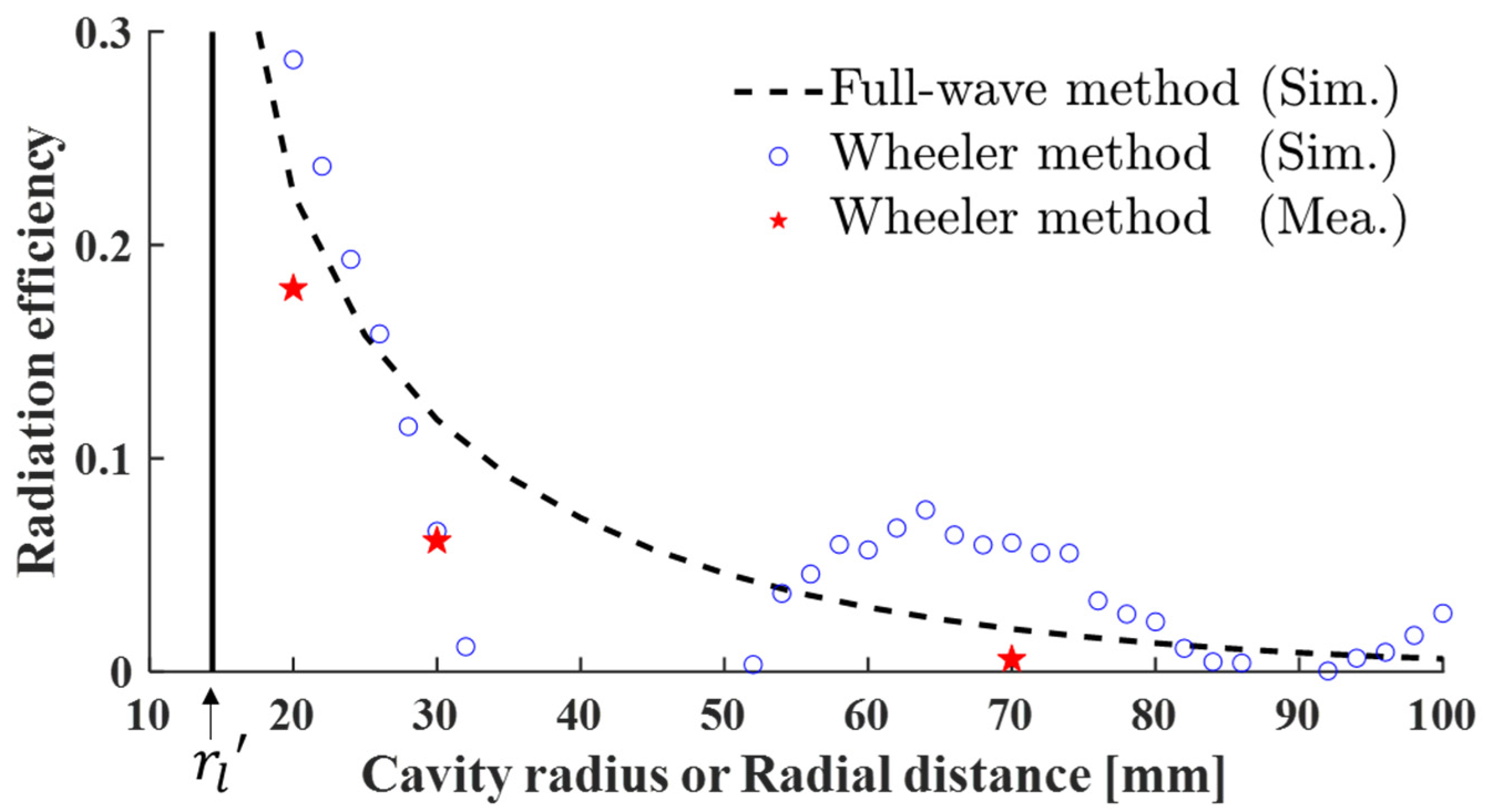
3.2.2. Measurement Result

The reflection characteristics measurement of the antenna was carried out with a vector network analyzer (VNA). The antenna radiation efficiency measurement was conducted using three different radiation shields to measure the resistance of the antenna in each case. The radiation efficiency η W R measured at 400 MHz is compared with the two simulation results in Figure 9. As the cavity radius becomes larger than the radian length, the error due to the cavity mode of the shield itself [30] is similarly confirmed in the measurement and simulation. The measurement results are in good agreement with the simulation results using the Wheeler method.
The efficiency values measured with a radiation shield having a radius (20 mm) close to the radian length r l (14.4 mm) is compared with the simulated values in Figure 10. The calculated error from 300 to 600 MHz is less than 3%.
This study is the first to experimentally validate the Wheeler method for the condition of lossy media. In previous studies of modified radiation efficiency, an ideal dipole or source was used or limited only to numerical analysis. In comparison, we designed and measured a practical UHF band NMHA that is applicable for submerged scenarios using an artificial lossy material. The radiation efficiency measured at the theoretical radian length is in good agreement with that proposed in a previous study [16].
Table 2 summarizes the performance comparisons between the proposed method and the state-of-the-art method. The proposed method uses the change in the resistance characteristic inside the cavity, whereas the principle of the other methods is based on the power of the electromagnetic field. It is noted that the proposed method measured the radiation efficiency only via the Wheeler cap, whereas [32] requires a lot of space and chambers for the measurement, including a shielded room. Therefore, the proposed method measures radiation efficiency in a fast and inexpensive way.

4. Conclusions

We propose the Wheeler method to measure the radiation efficiency of an antenna submerged in lossy media as an alternative to gain comparison methods which are carried out in the far-field. The concept of modified radiation efficiency in lossy media has been studied but is still limited to theory and simulation [16,17,26,27]. This work empirically studies the application method of the Wheeler method to achieve a breakthrough in the limitations of previous studies. Also, the radiation efficiency measured at the theoretical radian length is highly correlated with that proposed in a previous study [16], indicating that this method can be further applied to different frequencies and scenarios in the future.
The proposed method achieves very fast and inexpensive efficiency measurements without the need for other antennas or an expensive chamber. Additionally, the modified radiation efficiency can be used as a new figure of merit for evaluating submerged antennas for applications such as underwater, underground, and in-body communication systems. Furthermore, since the antenna radiation efficiency and propagation loss can be separated using the method presented in [26], it is expected to be useful for calculating the link budget of submerged channel modeling scenarios.

Author Contributions

Research conceptualization and methodology, D.C. and W.H.; Design and simulation, Y.O. and D.C.; Fabrication and measurement, Y.O. and D.C.; Writing-original draft, Y.O. and D.C.; Writing-review and editing, Y.O., J.-Y.L., and W.H. For other cases, all authors have participated. All authors have read and agreed to the published version of the manuscript.

Funding

This work was supported in part by the National Research Foundation of Korea (NRF) grant funded by the Korean Government (MSIT) under Grant 2018R1A4A1025679, in part by the Basic Science Research Program through the NRF of Korea funded by the Ministry of Education under Grant 2018R1A6A3A01013261.

Institutional Review Board Statement

Not applicable.

Informed Consent Statement

Not applicable.

Data Availability Statement

Not applicable.

Acknowledgments

The authors would like to thank ANSYS Korea for their generous support.

Conflicts of Interest

The authors declare no conflict of interest.

References

  1. Wheeler, H. Fundamental limitations of small antennas. Proc. IRE 1947, 35, 1479–1484. [Google Scholar] [CrossRef]
  2. Chu, L.J. Physical limitations of omni-directional antennas. J. Appl. Phys. 1948, 19, 1163–1175. [Google Scholar] [CrossRef] [Green Version]
  3. Gustafsson, M.; Sohl, C.; Kristensson, G. Physical limitations on antennas of arbitrary shape. Proc. R. Soc. A 2007, 463, 2589–2607. [Google Scholar] [CrossRef] [Green Version]
  4. Sievenpiper, D.F.; Dawson, D.C.; Jacob, M.M.; Kanar, T.; Kim, S.; Long, J.; Quarfoth, R.G. Experimental validation of performance limits and design guidelines for small antennas. IEEE Trans. Antennas Propag. 2012, 60, 8–19. [Google Scholar] [CrossRef]
  5. Wheeler, H.A. The radiansphere around a small antenna. Proc. IRE 1959, 47, 1325–1331. [Google Scholar] [CrossRef]
  6. McKinzie, W. A modified Wheeler cap method for measuring antenna efficiency. In Proceedings of the IEEE Antennas and Propagation Society International Symposium 1997. Digest, Montreal, QC, Canada, 13–18 July 1997; Volume 1, pp. 542–545. [Google Scholar] [CrossRef]
  7. Johnston, R.H.; McRory, J.G. An improved small antenna radiation-efficiency measurement method. IEEE Antennas Propag. Mag. 1998, 40, 40–48. [Google Scholar] [CrossRef]
  8. Smith, G. An analysis of the Wheeler method for measuring the radiating efficiency of antennas. IRE Trans. Antennas Propag. 1977, 25, 552–556. [Google Scholar] [CrossRef]
  9. Ashkenazy, J.; Levine, E.; Treves, D. Radiometric measurement of antenna efficiency. Electron. Lett. 1985, 21, 111. [Google Scholar] [CrossRef]
  10. Newman, E.; Bohley, P.; Walter, C. Two methods for the measurement of antenna efficiency. IRE Trans. Antennas Propag. 1975, 23, 457–461. [Google Scholar] [CrossRef]
  11. Tan, H.-P.; Diamant, R.; Seah, W.K.; Waldmeyer, M. A survey of techniques and challenges in underwater localization. Ocean Eng. 2011, 38, 1663–1676. [Google Scholar] [CrossRef] [Green Version]
  12. Chong, C.-Y.; Kumar, S. Sensor networks: Evolution, opportunities, and challenges. Proc. IEEE 2003, 91, 1247–1256. [Google Scholar] [CrossRef] [Green Version]
  13. FitzGerrell, R.; Haidle, L. Design and performance of four buried UHF antennas. IRE Trans. Antennas Propag. 1972, 20, 56–62. [Google Scholar] [CrossRef]
  14. Vuran, M.C.; Silva, A.R. Communication through soil in wireless underground sensor networks—Theory and practice. In Distributed Cooperative Laboratories: Networking, Instrumentation, and Measurements; Springer Science and Business Media LLC: Berlin/Heidelberg, Germany, 2009; pp. 309–347. [Google Scholar]
  15. Abbasi, Q.H.; Qaraqe, K.; Rehman, M.U.; Alomainy, A. Advances in Body-Centric Wireless Communication: Applications and State-of-the-Art; IET: London, UK, 2016. [Google Scholar]
  16. Karlsson, A. Physical limitations of antennas in a lossy medium. IEEE Trans. Antennas Propag. 2004, 52, 2027–2033. [Google Scholar] [CrossRef]
  17. Lee, J.; Nam, S. Effective area of a receiving antenna in a lossy medium. IEEE Trans. Antennas Propag. 2009, 57, 1843–1845. [Google Scholar] [CrossRef]
  18. Merli, F.; Fuchs, B.; Mosig, J.R.; Skrivervik, A.K. The effect of insulating layers on the performance of implanted antennas. IEEE Trans. Antennas Propag. 2011, 59, 21–31. [Google Scholar] [CrossRef]
  19. Liao, Y.; Hubing, T.H.; Su, D. Equivalent circuit for dipole antennas in a lossy medium. IEEE Trans. Antennas Propag. 2012, 60, 3950–3953. [Google Scholar] [CrossRef]
  20. IEEE. IEEE standard for definitions of terms for antennas. In IEEE Std 145-2013 (Revision of IEEE Std 145-1993); IEEE: Piscataway Township, NJ, USA, 2014; pp. 1–50. [Google Scholar]
  21. Miah, S.; Khan, A.N.; Icheln, C.; Haneda, K.; Takizawa, K.-I. Antenna system design for improved wireless capsule endoscope links at 433 MHz. IEEE Trans. Antennas Propag. 2019, 67, 2687–2699. [Google Scholar] [CrossRef] [Green Version]
  22. Bao, Z.; Guo, Y.-X.; Mittra, R. An ultrawideband conformal capsule antenna with stable impedance matching. IEEE Trans. Antennas Propag. 2017, 65, 5086–5094. [Google Scholar] [CrossRef]
  23. Kim, S.; Shin, H. An ultra-wideband conformal meandered loop antenna for wireless capsule endoscopy. J. Electromagn. Eng. Sci. 2019, 19, 101–106. [Google Scholar] [CrossRef] [Green Version]
  24. Kaim, V.; Kanaujia, B.K.; Kumar, S.; Choi, H.C.; Kim, K.W.; Rambabu, K. Ultra-miniature circularly polarized CPW-fed implantable antenna design and its validation for biotelem-etry applications. Sci. Rep. 2020, 10, 6795. [Google Scholar] [CrossRef] [Green Version]
  25. Holloway, C.L.; Shah, H.A.; Pirkl, R.J.; Young, W.F.; Hill, D.A.; Ladbury, J. Reverberation chamber techniques for determining the radiation and total efficiency of antennas. IEEE Trans. Antennas Propag. 2012, 60, 1758–1770. [Google Scholar] [CrossRef]
  26. El-Saboni, Y.; Zelenchuk, D.E.; Conway, G.A.; Scanlon, W.G. Assessing the intrinsic radiation efficiency of tissue-implanted UHF antennas. IEEE Trans. Antennas Propag. 2020, 68, 491–499. [Google Scholar] [CrossRef] [Green Version]
  27. Manteghi, M.; Ibraheem, A.A.Y. On the study of the near-fields of electric and magnetic small antennas in lossy media. IEEE Trans. Antennas Propag. 2014, 62, 6491–6495. [Google Scholar] [CrossRef]
  28. Cheng, X.; Wu, J.; Blank, R.; Senior, D.E.; Yoon, Y.-K. An omnidirectional wrappable compact patch antenna for wireless endoscope applications. IEEE Antennas Wirel. Propag. Lett. 2012, 11, 1667–1670. [Google Scholar] [CrossRef]
  29. Huang, Y.; Narayanan, R.; Kadambi, G. Electromagnetic coupling effects on the cavity measurement of antenna efficiency. IEEE Trans. Antennas Propag. 2003, 51, 3064–3071. [Google Scholar] [CrossRef]
  30. Choo, H.; Rogers, R.; Ling, H. On the Wheeler cap measurement of the efficiency of microstrip antennas. IEEE Trans. Antennas Propag. 2005, 53, 2328–2332. [Google Scholar] [CrossRef]
  31. Groiss, S.; Bardi, I.; Biro, O.; Preis, K.; Richter, K. Parameters of lossy cavity resonators calculated by the finite element method. IEEE Trans. Magn. 1996, 32, 894–897. [Google Scholar] [CrossRef]
  32. Conway, G.A.; Scanlon, W.G.; Orlenius, C.; Walker, C. In situ measurement of UHF wearable antenna radiation efficiency using a reverberation chamber. IEEE Antennas Wirel. Propag. Lett. 2008, 7, 271–274. [Google Scholar] [CrossRef]
Figure 1. Illustration of conventional gain comparison method which evaluates radiation characteristics for antenna in lossy media.
Applsci 11 01862 g001
Figure 2. Simulation setup for calculation of radiated power.
Applsci 11 01862 g002
Figure 3. (a) Structure of the antenna isolated from the lossy medium by the insulating layer and the Wheeler cap. (b) Equivalent circuit model of antenna within the Wheeler cap.
Applsci 11 01862 g003
Figure 4. Geometry of simulation setup: (a) cross-sectional view of NMHA and (b) with metallic cavity, (c) perspective view. ( d a = 20, p a = 3, h a = 6.4, t a = 0.8, r i = 15, h i = 40, t i = 1, r g = 500, t g = 1, t w = 5. Unit: mm.
Applsci 11 01862 g004
Figure 5. The radiation efficiency η W R versus cavity radius r w with changes in the dielectric constant. η M R is marked with a dash for the same color line. The radian length r l is marked with black lines.
Applsci 11 01862 g005
Figure 6. The radiation efficiency η W R versus cavity radius r w with changes in the conductivity and η M R versus radial distance d r is marked with a dash for the same color line. The radian length r l is marked with black lines.
Applsci 11 01862 g006
Figure 7. Illustration of (a) normal-mode helical antenna and capsule-shaped insulation layer, (b) hemisphere-shaped radiation shield.
Applsci 11 01862 g007
Figure 8. Measurement system for evaluating the radiation efficiency of a submerged antenna.
Applsci 11 01862 g008
Figure 9. The measured and simulation radiation efficiency η M R versus cavity radius r w and simulation η M R versus radial distance d r . The radian length r l is marked with black lines.
Applsci 11 01862 g009
Figure 10. The measured and simulated radiation efficiency ( d r = r w   = 20 mm).
Applsci 11 01862 g010
Table 1. Fabricated Antenna Parameter.
Parameter d a p a h a t a r i
Value (mm)9320.85
Parameter h i t i r g t g t w
Value (mm)1311000.070.07
Table 2. Comparison of the proposed method with other works.
Ref.Required Measurement Facilities or Essential AccessoriesAcquisition Method for Radiation EfficiencyError Between Simulation and Measurement
[32]2.4 × 2.4 × 2.4 m (Shield room), reference antennaAverage static power transfer function at different 3 position<4.5%
[26]-Power integral normal to the sphereOnly simulation
This workLossy medium, Wheeler capVariation of the input resistance<3%
Publisher’s Note: MDPI stays neutral with regard to jurisdictional claims in published maps and institutional affiliations.

