Article

Measurement of Amount for Steel Abrasive Material Transported by Special Scraper Conveyor

1
Faculty of Mining, Ecology, Process Control and Geotechnologies of the Technical University of Košice, Park Komenského 14, 040 01 Košice, Slovakia
2
Bulk Solids Centre, ENET Centre, VSB—Technical University of Ostrava, 17. Listopadu 2172/ 1, 708 00 Ostrava-Poruba, Czech Republic
3
Faculty of Mining and Geology, VSB—Technical University of Ostrava, 17. Listopadu 2172/ 15, 708 00 Ostrava-Poruba, Czech Republic
4
Faculty of Manufacturing Technologies, Technical University of Košice with a Seat in Prešov, Bayerova 1, 080 01 Prešov, Slovakia
5
Faculty of Mechanical Engineering, Technical University of Košice, Letná 9, 042 00 Košice, Slovakia
*
Author to whom correspondence should be addressed.
Appl. Sci. 2021, 11(4), 1852; https://doi.org/10.3390/app11041852
Submission received: 21 January 2021 / Revised: 12 February 2021 / Accepted: 16 February 2021 / Published: 19 February 2021
(This article belongs to the Section Mechanical Engineering)

Abstract

:
Results obtained from measuring the required amount of steel abrasive material with various fragmentations, which is transported by a special kind of scraper conveyor, offers information that is useful for operators of the abrasive blast cabinets. The presented article describes an innovative methodology developed for determination of the most relevant operational parameters relating to the above-mentioned situation. The most important parameters in this case are: the optimal amount of the abrasive material, the conveying speed of the scraper conveyor and the feeding of the conveyor with regard to partial or full elimination of instable operational area. Elimination of the instable operational area is possible by means of a simple constructional modification of the given conveying system according to the results obtained from experimental investigation, which was performed using special, originally developed laboratory testing equipment.

1. Introduction

In addition to the very familiar belt conveyor and the scarcely less familiar bucket elevator, there are a number of alternative mechanical techniques that are commonly used to carry, drag or scrape bulk solids from one location to another [1]. Gathering floor conveyors represent such a kind of raw material transport.
The scraper conveyor is mostly used in the mining industry. It is an important part of fully mechanized equipment (Wu et al. [2]). However, the scraper conveyors can also be efficiently applied in other industrial branches—for example, in the building industry, agriculture or metallurgy. Utilization of the gathering floor conveyors is described by Landry et al. [3]. Technical development of these conveyors is not finished yet. Wang [4] has dealt with the new development of longwall mining equipment based on automation and intelligent technology for thin seam coal. Within a proposal of new mining equipment, gathering floor conveyors were considered as a possibility.
Research of problems concerning the gathering floor conveyors is presented in many scientific works [5,6,7,8,9,10,11,12,13,14,15]. Chunzhi and Guoying [5] realized dynamic modeling of a scraper conveyor sprocket transmission system and simulation analysis. The dynamic model includes sprockets, chains, middle troughs, transitional troughs and scrapers. The main characteristics of constructional parameters concern the components. Xia et al. [6] explored the discrete element method, which was combined with the wear model. After validation of the wear simulation, was designed for different intrinsic parameters. Zhao et al. [7] investigated the fault of a scraper conveyor under time-varying load conditions by a diagnosis method intended for gear faults. Pei and Wang [8] performed failure analysis and improvement of a chute of a scraper conveyor. Suitable simulation methods are often used in order to investigate gathering floor conveyors. Finite element analysis of round-link chains of scraper conveyors based on the software ANSYS (R1 2020, Ansys, Inc., Canonsburg, PA, Pennsylvania, 1970) was conducted by Min et al. [9]. Mao et al. [10] conducted numerical simulation studies of a tension automatic control system using a scraper conveyor. Liu et al. [11] determined the horizontal bending angle of the scraper conveyor, which has a great influence on the running resistance, on the current energy consumption and on the coal winning efficiency of the working surface using a simulation model. The results showed that the current energy consumption of the scraper conveyor was reduced by 31% when the horizontal bending angle was 0.66°. Dynamic analysis of a round-link chain for a scraper conveyer under blocked chain conditions was carried out in Xiao-yan [12]. Scraper conveyor dynamic modeling and numerical simulations were performed by Zhang et al. [13]. They created the shape function of the scraper conveyor circuitry. The authors also realized the computer automatic modeling of the example, which was carried with a digital simulation of all working conditions (i.e., starting, freely stopping, abnormal load, chains blocked, the difference of chain’s pitch and the chain wheel polygon effect). Lu et al. [14] presented the simulation method of speed control, which is based on the load characteristic of the permanent magnet direct-driven system determined for mining scraper conveyors using MATLAB/Simulink module. Wang et al. [15] analyzed the particle size and velocity distributions of bulk coal by the discrete element method. They also studied the influence of the transport velocity, coefficient of static friction between particles and mass flow rate. The results showed that the large particles gather at higher positions, whereas small particles gather at lower positions.
The most important task during operation of the gathering floor conveyors is the correct functioning of them, similarly to the case of all other types of conveyors, taking into consideration requirements of continuous transport of bulk solids as well as with regard to correct functioning of the transitional chutes. Chutes are very important on most conveyors. Mikusova et al. [16] used finite element method (FEM) in their examination and in [17] the conveyor overflow was analyzed in terms of applied forces. Wang and Yang [18] improved the design and analysis of the transitional chute of a scraper conveyor. In this work, the experiment and analysis can conclude that the forces, which influence the wear of the transitional chute, are dependent on the transition arc radius but not on the transitional angle.
Another important constructional part of the gathering floor conveyor is the ramp plate. Ren et al. [19] analyzed and calculated the ramp plate, which is the key component of the scraper conveyor. An effective and correct operation of the gathering floor conveyors requires their continuous monitoring. Chen et al. [20] studied automation and intelligent control technologies of scraper conveyors with fully mechanized faces. In their work, new information is presented with an application possibility not only for the gathering floor conveyors, but also for other kinds of conveyors.
Wear failure of the chute is the main form of failure of the scraper conveyor.
The behavior of the transported material is another interesting area concerning the wide spectrum of the conveyors determined for transport of bulk solids. The scientific literature usually offers information about transport of bulk solids, which is realized by means of the belt conveyors. Hastie et al. [21] performed validation of particle flow through a conveyor transfer hood via particle velocity analysis. Similar problems are also resolved in other publications. Hastie and Wypych [22] investigated three discrete element methods (DEMs) in detail that are applicable for granular cohesionless materials. Application of the DEM provided data concerning quantification and prediction of the particle velocity through the transfer hood, which were further processed using MATLAB. Hastie et al. [23] discussed how to adjust the material, interactions and geometrical properties of particle elements so that DEM models provide results appropriate to the actual material used. Grima et al. [24] designed and commissioned the new large scale wall friction tester in order to measure the wall friction angles of dry and wet bulk materials with a wide particle size distribution.
Research and experimental investigations performed in the area of various conveyors—namely, in the area of scraper conveyors—belong among less explored research fields, because realization of such a kinds of investigation is not a simple task. This article introduces the new results obtained thanks to application of a special experimental methodology and offers opportunities for practical utilization of these results.

2. Materials and Methods

It is a well-known fact that transport of bulk solids is considered to be a specific technological process, which is unavoidable within the framework of diverse technological systems operating in many industrial branches. Different transport machines and transport equipment with various design solutions, transport capacities and conveying speeds are usually used. Operators of the transport machines have to dispose of suitable information in order to ensure safe and reliable functioning of the whole transport system. The technological centers with the installed conveying technologies must be precisely calibrated and correctly operated. Information concerning dependence of the amount of transported material on the conveying speed and on charging of the conveying system is necessary for the operator of the given transport system. The above-mentioned dependence is one of the most important pieces of information in the case of many transport systems, especially in the case of conveying systems designed for continual transport of bulk materials. One of such transport machines, which are used for conveying of bulk solids, is the scraper conveyor. A specific constructional modification of the scraper conveyor is for gathering of abrasive material from the floor into the abrasive blast cabinets, because design solutions and dimensions of this conveyor are suitable for installation inside of the blast cabinet area.
The main operational part of this special scraper conveyor is the movable frame equipped with the transversally fixed scraping membranes, which are rotationally fitted to the frame in the pins on both sides of the membranes (Figure 1). The moveable frame moves longitudinally, whereas it oscillates forward and backward on the rolling support installed within the basic static frame. Functioning of this conveyor consists of two specific phases. The first phase encompasses shifting of the moveable frame forwards, together with the scraping membranes, in the material transport direction. The membranes are fixed in vertical positions during this phase and in this way they gather or scrape the material. Thus, this is the conveying stroke of the moveable frame. The second phase is shifting of the moveable frame to scrape membranes backwards, whereas the membranes are released during this reverse motion. For this reason, the material is not transported in this case—i.e., this return stroke is an empty stroke. Repeating of these two phases (two kinds of strokes) creates a closed operational cycle with periodical shifting forwards of the transported material. Propulsive energy is ensured by electric drive of the conveyor.
Realization of various experimental measurements during current operation of the real transport equipment—for example, measuring of actual amount of the transported material—is a very demanding process and as such it is usually almost impossible. Therefore, most of the relevant operational information and data that are obtained from producers of the transport machines (including the conveyors) are based only on the calculations, theoretical analyses or computer simulations using, for example, DEMs.
Taking into consideration the above-mentioned facts, our research team developed special experimental testing equipment within the framework of own research activities. This specific experimental testing equipment enables the simulation of the real operational conditions of the laboratory conditions and, in this way, measuring of the transported amount of bulk material in accordance with the real operation.

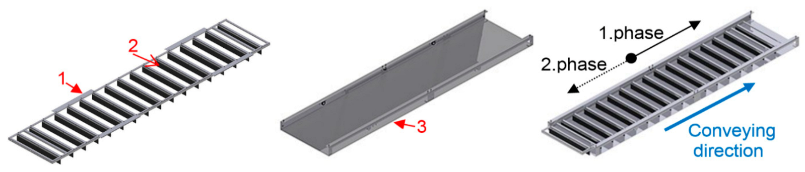
2.1. Experimental Testing Equipment and Measured Parameters

The original experimental testing equipment, together with an innovative measuring methodology, is proposed and developed in order to measure the relevant parameters, which enables us to describe the amount of material samples transported by the laboratory scraper conveyor. The real abrasive material, which is transported in the real abrasive blast cabinet, is simulated by means of these material samples (Figure 2).
The testing stand is equipped with a functional segment of the above-described special scraper conveyor, which consists of the following parts: the basic frame shaped in the form of a trough, the moveable frame with the scraping membranes and the linear driving mechanism. The tension forces and the thrust forces are induced in the linear driving mechanism and they move the frame of the conveyor forwards and backwards cyclically. These forces are measured by means of a strain gauge measuring system, whereas the strain gauge sensor is situated in the connecting point between the driving mechanism and the moveable frame. Weights of the transported steel abrasive material and the material volumetric parameters are sensed by the strain gauge, too. Scheme of the experimental testing equipment, together with the measuring points, is illustrated in Figure 3.

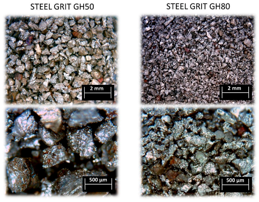
2.2. Specification of the Transported Material

The whole measuring process was performed using the samples of two different steel abrasive materials—namely, STEEL GRIT GH50 and STEEL GRIT GH80. The microscopic photos of these materials are shown in Figure 4. These materials are the product range of the WISTA company, and according to the company standard, the abbreviation GH represents the abrasive hardness in the range of 650–850 HV and the numerical designation complements the information on the grain size of the material, which is (50) 300–850µm and (80) 120–500 µm.

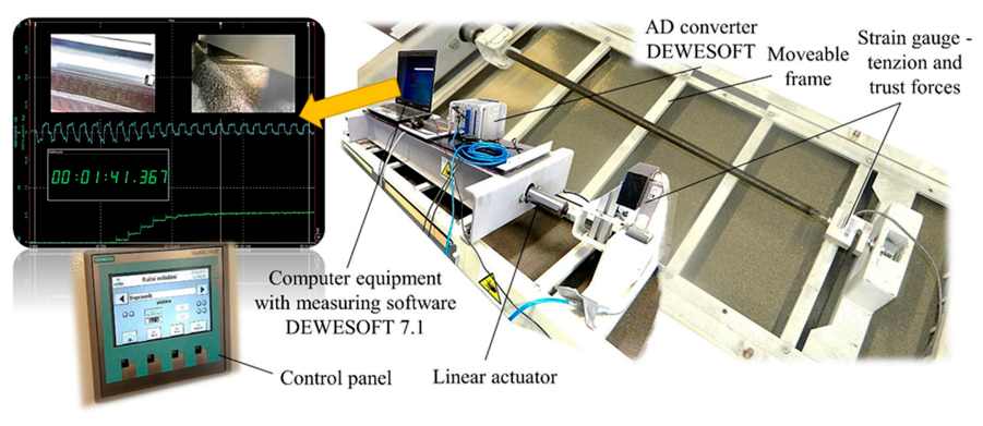
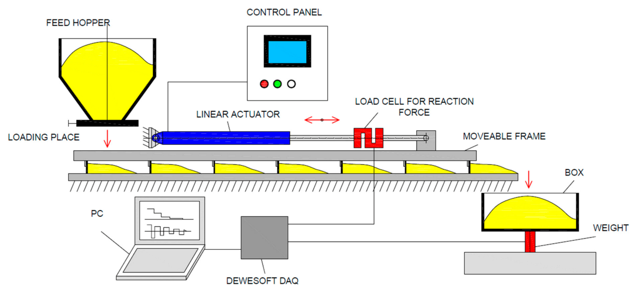
2.3. Measuring System

The applied measuring system DEWESOFT (Version 7.1, DEWEsoft, Trbovlje, Slovenia, 2000) contains the preprepared measuring modules (measuring cards) specified for interconnection of various sensors with the analogous or digital output. The main advantage of this measuring system consists of a possibility to measure and to evaluate all the output parameters simultaneously. The following parameters were measured during the experimental operation of the special scraper conveyor: tension and thrust forces in the linear driving mechanism, the real amount of the transported material (i.e., transport capacity of the conveyor) and duration of the conveying stroke. The scheme of the measuring chain with the measuring system, DEWESOFT 7.1 is shown in Figure 5.

2.4. Measuring Procedure
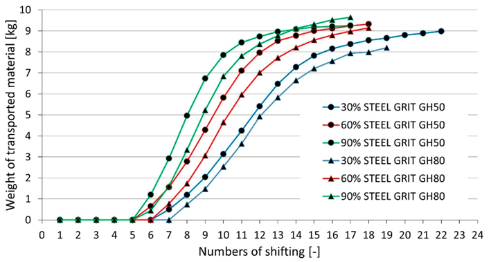
The whole measuring procedure was divided into two phases:
(1) The first phase of the measuring process defines the individual shifting speeds specified for the given material, which is transported in the scraper conveyor. Setting of the individual shifting speed levels was performed in the case of an empty conveyor—i.e., during operation of the conveyor without material—using the industrial PC equipped with the frequency converter, whereas the individual shifting speed values were adjusted to the levels of 30%, 60% and 90%.
(2) The second phase started with feeding of 14 kg of the abrasive materials, STEEL GRIT GH50 and GH80, into the conveyor. This initial amount of the material was spread uniformly on the whole bottom surface of the conveyor, in order to create a durable filling charge (durable layer) of material in the conveyor. The following step ensures a gradual feeding of the precisely weighted individual amounts of the abrasive materials, STEEL GRIT GH50 and GH80 (Figure 6)—namely: 5, 10, 15, 20, 25, 30, 35, 40 and 45 kg. Subsequently, the abrasive material was refilled in the rear part of the conveyor according to the diagram in Figure 3. The measured parameters are: time, which is necessary for transport of the given amount of abrasive material into the collecting box; the actual weight of material in the collecting box; the actual reaction forces arising in the driving mechanism. Two cameras monitored the conveyor in order to record the time behavior of the conveying stroke and amount of the discharged material.

3. Results

Relation (2) was determined for calculation of the amount Q (i.e., the transport capacity of the conveyor) for the transported steel abrasive material STEEL GRIT GH50. The average mass m of the given abrasive material, which is transported during one stroke, is defined by relation (1). It is evident from this relation that the value m depends on the material shifting speed v%. This relation is based on an exponential equation, which is obtained from the measured data according to Figure 13.
y = 0.05757 · e 0.0108 x   = >   m = L · 1 · 1994 · e 0.0108 · v %
Q = 3.6 · L · 1.1994 · e 0.0108 · v % t = 2.159 · L · e 0.011 · v % t   [ t · hod 1 ]
where:
m—average mass of the steel abrasive material, STEEL GRIT GH50, transported during one stroke and depending on the material shifting speed v% [kg];
Q—amount of the transported steel abrasive material, STEEL GRIT GH50 (transport capacity of conveyor) [t·hour−1];
L—width of the conveyor (i.e., length of the scraping membrane) [m];
t—duration of the stroke in the transported direction [s];
v%—shift speed of the transported material [%].
The analogical similar procedure was applied in order to determine the amount of the second kind of the transported steel abrasive material, STEEL GRIT GH80.
The shifting speeds of the transported material, which are calculated as a ratio of the stroke length (which is known) and the measured stroke duration, are shown in Table 1.

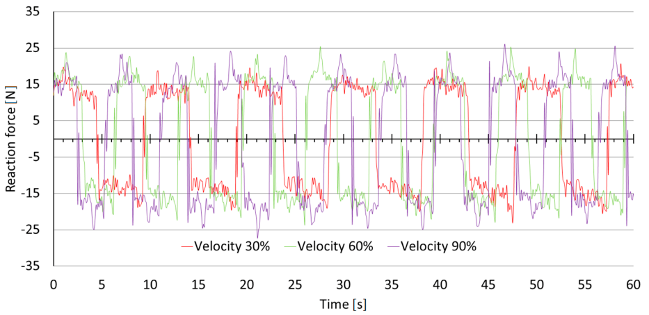
3.1. Measuring of Reaction Forces during Conveyor Operation Without Material

Figure 6 illustrates the results obtained from measuring the reaction forces—i.e., such forces that are acting on the driving mechanism during operation of the scraper conveyor without material. The results of this measuring process are presented in the form of the recorded time behaviors of the reaction forces. These results depend on the material shifting speeds, which were adjusted at the levels of 30%, 60% and 90%. The accurate values of the corresponding stroke times, i.e., duration of the stroke, can be obtained from the given time behaviors of the reaction forces and are in accordance with Table 1.

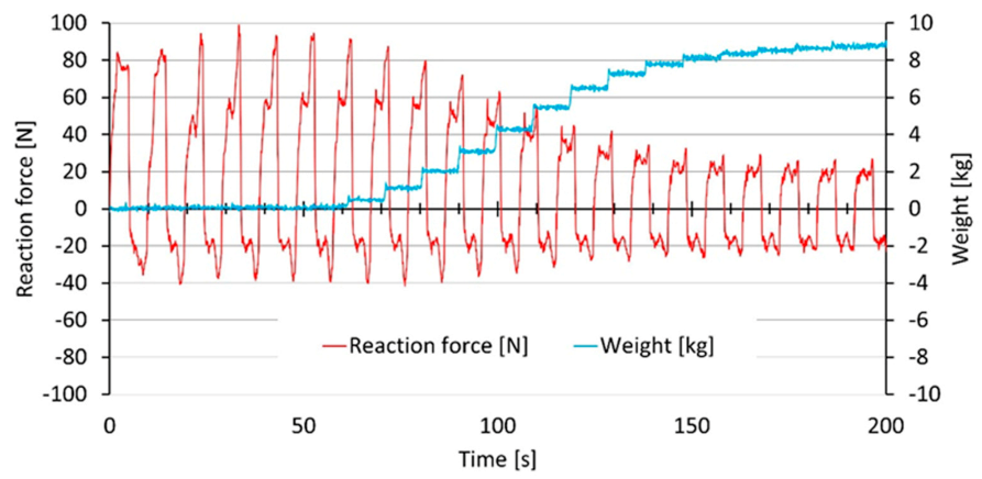
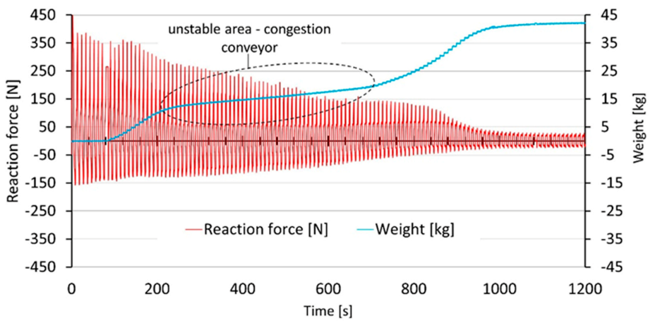
3.2. Measuring of Reaction Forces Acting on the Driving Mechanism during Conveyor Operation with Material

Table 2 summarizes combinations of conditions for all the performed measurements of the reaction forces acting on the driving mechanism.
Figure 7 illustrates the stable results obtained from measuring the reaction force acting on the driving mechanism at the 30% level of shifting speed for the abrasive material, STEEL GRIT GH50, transported in the conveyor. Time behavior of the reaction force depends on feeding of the conveyor with 10 kg of the abrasive material.
Figure 8 illustrates the unstable results obtained from measuring of the reaction force acting on the driving mechanism at the 30% level of shifting speed for the abrasive material, STEEL GRIT GH50, transported in the conveyor. Time behavior of the reaction force depends on feeding of the conveyor with 45 kg of the abrasive material. With this filling, we see that the overcrowded conveyor loses transport efficiency and thus creates an unstable area of operation of the equipment. For this reason, energy consumption and the time required for transport increase. With a one-time filling of 45 kg, we see that the device is able to eliminate this overcrowded state over time and starts working again with greater efficiency. If the material is supplied to the system continuously, the transport system is not able to get out of the overcrowded state and the transport efficiency drops from about 360 to 48 kg per hour.
Figure 9 demonstrates a dependence of real weight of the transported materials, STEEL GRIT GH50 and GH80, on the number of strokes during gradual feeding of the conveyor with 10 kg of this material at the 30%, 60% and 90% levels of the material shifting speed. It is evident from Figure 9 that higher level of the material shifting speed causes increasing of the transport process efficiency and vice-versa.
Figure 10 demonstrates a dependence of real weight of the transported materials, STEEL GRIT GH50 and GH80, on the number of strokes during gradual feeding of the conveyor with 25 kg of this material at the 30%, 60% and 90% levels of the material shifting speed. It can be seen in this graph that at the lowest 30% level of the material shifting speed, an unstable area is created due to the filling of the conveyor, which reduces the transported amount over time. At 60% of the material shifting speed, it can be seen that an unstable area begins to form, and this determines the limit beyond which we must not reach when operating the transport equipment. The highest shifting speed of 90%, even when filling 25 kg, shows stable transport without problems.
Figure 11 demonstrates a dependence of real weight of the transported materials, STEEL GRIT GH50 and GH80, on the number of strokes during gradual feeding of the conveyor with 45 kg of this material at the 30%, 60% and 90% levels of the material shifting speed. It can be seen in the graph that, unlike the previous graph, there is already an unstable area at each shifting speed during material transport. It is clear from this that it is not possible to operate the device during this filling. In this way, a selection was determined in which the device is able to operate in a stable state for all three speeds. It was found to be stable for fillings of up to 15 kg and speeds of 30%, 60% and 90% for STEEL GRIT GH50 and GH80
Taking into consideration one stroke of the conveyor, so there are obtained behaviors on Figure 12, which presents a dependence of weight of the transported steel abrasive materials, STEEL GRIT GH50 and GH80, in the case of one stroke on sequence of the stroke during gradual feeding of the conveyor with 10 kg of this material and at the 30%, 60% and 90% levels of the material shifting speed.
Table 3 summarizes the calculated amounts of the transported steel abrasive materials, STEEL GRIT GH50 and GH80, at the 30%, 60% and 90% levels of the conveyor shifting speed within the stable transport area.
Figure 13 illustrates another relevant dependence—namely, the dependence of the average value for amount of the transported material, STEEL GRIT GH50, on the adjusted shifting speed level according to Table 3. We can observe that up to 50% shifting speed level the function is linear and from 50% it grows exponentially, which shows greater efficiency of the device at these speeds.
Taking into consideration one stroke of the conveyor, Figure 14 describes a dependence of the average value for amount of the transported material, STEEL GRIT GH50, in the case of one stroke on the adjusted shifting speed level according to Table 3.

4. Discussion

The results obtained from evaluation of the performed experimental measurements enabled us to determine the time interval, which is necessary for transport of the given amount of the steel abrasive materials, STEEL GRIT GH50 and GH80, using the above-mentioned and described special scraper conveyor. Due to the abrasive material being conveyed, the conveyor rakes are made of rubber to last as long as possible in this abrasive environment. The elasticity and flexibility of the rubber rake means that if the filling system is improperly filled and set, the transport efficiency of the device may decrease. The amount of transported material depends on the efficiency of the gathering process and on the moving force, which is required in order to compensate all the motional resistances. The graphs containing the measured and evaluated values are useful to specify the transported amount of material in the case of an adjusted shifting speed level. Higher level of the material shifting speed increases efficiency of the transport process and vice versa. This finding is visible in Figure 9. It can also be seen that the STEEL GRIT GH50 and GH80 materials have similar traffic curves, which means a similar traffic amount over time, as evidenced by the outputs according to Table 3. The analogous dependence is valid between the rising values of conveyor feeding and increasing efficiency of the conveying process. However, there is a limitation in this case because the amount of the transported material in the conveyor must not exceed the values in the interval 15–25 kg plus weight of the already mentioned durable filling charge, which is placed on the bottom surface of the conveyor trough. Exceeding this material weight limit causes an instable operational state. Changing of the shifting speed of the scraping membranes allows variable shifting of the instability limit, which is visible in Figure 11, where unstable areas occur at 30% and 60%, but increasing to 90% of the speed stabilizes the transport process. According to Table 3, the highest possible transport quantity is reached at a speed of 90% and a filling of 15 kg for the STEEL GRIT GH80 material—namely, 1.634 tons per hour. Thanks to all these important findings, it can be seen that for this type of transport equipment it is necessary to determine the boundaries where the equipment is still operating stably. Without the use of this knowledge, unnecessary losses can occur in practice due to the system being overwhelmed, which can lead to its malfunction. The results also show that if there is an unintentional congestion of the system, the operator can increase the feed rate to 90%, thus setting traffic curves from an unstable zone to a stable zone, or if the device is more congested, to a slightly unstable zone and after eliminating the problem. When the filling is reduced, the system can return to the original feed rate.

5. Conclusions

This scientific research work presents results concerning the behavior of an innovative collection transport system used for the transport of highly abrasive materials. Due to the high abrasiveness, the construction of the machine is designed so that the active components of the machine wading in the abrasive material are made of materials that are as resistant to the effects of abrasion as possible. The flexible material of the transport rakes has been chosen, which is ideal for an abrasive environment, but this flexibility of the transport component causes uncertainties in the transport system regarding the linearity of the transport function of this system. Although it is possible to eliminate these uncertainties by changing the material of the active components, i.e., by replacing the rubber with a solid material, this solid material does not withstand the abrasive transport process. For this reason, a compromise must be sought with this new transport system. This compromise is to find stable and unstable areas of transport, when the system is still working and when, on the contrary, it is no longer working. Subsequently, the solution is to use only stable areas of the equipment when transporting the abrasive material. For this reason, the system was measured in different filling and speed setting modes. Two grains of a highly abrasive material, STEEL GRIT, were used for this measurement—see Figure 4. With this material, the actual values of transport capacity were measured depending on the speed of movement of wiper membranes and on the conveyor load—see Table 2. Experimental measurements were performed using a special test and measuring equipment that was designed in the Bulk Solids Centre Czech Republic at the Technical University Ostrava. The special test and measuring device consists of a functional segment of a collecting floor conveyor with installed measuring points (Figure 3). This measuring stand has proven to measure the behavior of the transported material along the transport line and has made it possible to measure the following operating characteristics: force required to move the wiper membranes, transport speed of bulk material, speed of wiper membrane movement and conveyor filling. The measurement of forces can be seen in the graph of Figure 6, where it is possible to observe positive forces when moving the rubber rakes of the empty conveyor system forwards and negative forces in the backward direction. The maximum dynamic peaks reach 25 N with this reaction force. If loose material is poured into the system, it resists movement, which can be seen in Figure 7 and Figure 8. In the forward movement, when the abrasive material is pushed in the direction of transport by means of the rake, we can observe an increase in the reaction force to values depending on the filling of the transport system. For a load of 10 kg, these reaction forces are around 100 N and for a load of 45 kg around 370 N. The backward movement also shows an increase in this reaction force, which is caused by the sliding of the bent rubber over the layer of abrasive material, where this layer serves to protect the lower part of the conveyor trough. The reaction forces of the return stroke are in the dynamic peaks at a load of 10 kg around 40 N and at a load of 45 kg around 150 N. It was found that the conveyor system was sufficiently designed, and during the measurements for all filling and speeds, this system was not stopped due to a well-designed drive with a sufficient excess supply of reaction force transmitted to the rakes. Based on other measured data, the areas of stability and instability of traffic were plotted in the graphs—see Figure 10 and Figure 11. From these graphs, we see that if the system is overloaded, the steepness of the transported volume curve decreases sharply. According to the observation of the device, this process is caused by rubber rakes. When moving forward, the rubber rake cannot sink its edge into the material if a state of overfilling occurs. The rake essentially forms the front part of the ski with its shape and thanks to this shape it does not fully fulfill the function of pushing the material in front of it, but on the contrary slides only after this material and pushes only a small amount of material in front of it with its edge. To avoid this situation, it is important to maintain a certain level of material in the device. This means filling the conveyor system so that this effect of twisting the rake does not occur. This limit as already mentioned is 15–25 kg. The width of this area is due to the possibility of using more speeds for transporting equipment, where we can observe from graph 10 that for filling 25 kg, speeds of 30% and 60% of the traffic are no longer stable, but for speeds of 90%, they are. The increased speed gives the rubber rake a higher ability to penetrate the edge into the abrasive material thanks to the increased dynamics of movement. Furthermore, it was observed that the behavior of the rake penetration into the material of a different grain size is similar in the stable range for GH50 and GH80, which have similar characteristics—see Figure 9—and similar transport quantities—see Table 3. This information can be fully applied in industrial practice in construction. Design of such a conveyor works on the principle of cyclic displacement of wiper membranes. For example, we can continue to work on adjusting the geometry and stiffness of the rake so that deformations of the rake do not occur. We can thus increase the filling limit of the system and increase the transport volume of the system, which is now limited due to the flexibility and construction of the rake. Thus, the presented methodology makes it possible to determine the dependence of the transported quantity on the transport speed by means of several measurements concerning the mechanical properties of the transported material. Based on these measurements, critical states can be observed during the transport process, which can then be used to set up the equipment so that they do not occur during transport and serve to find improvements in the transport system. Currently, these measured values are also used as validation parameters in the discrete element method to speed up the design process and the possibility of searching for other innovations in the virtual environment, which are a part of the related issues of Industry 4.0.

Author Contributions

Conceptualization, G.F.; methodology, D.G. and J.N.; investigation, J.Z. and M.T.; data analysis, G.F. and M.T.; writing—original draft preparation, V.M. and J.N.; writing—review and editing, G.F. and V.M. All authors have read and agreed to the published version of the manuscript.

Funding

This work is a part of these projects VEGA 1/0403/18, VEGA 1/0600/20, KEGA 012TUKE-4/2019, KEGA 013TUKE-4/2019, APVV SK-SRB-18-0053 and Innovative and additive manufacturing technology—new technological solutions for 3D printing of metals and composite materials, reg. no. CZ.02.1.01/0.0/0.0/17_049/0008407 financed by Structural Funds of Europe Union. Work is supported by Grant of SGS No. SP2021/55, Faculty of Mining and Geology, VSB—Technical University Ostrava, Czech Republic.

Institutional Review Board Statement

Not applicable.

Informed Consent Statement

Not applicable.

Data Availability Statement

Not applicable.

Conflicts of Interest

The authors declare no conflict of interest.

References

  1. Woodcock, C.R.; Mason, J.S. Bulk Solids Handling; Springer: Dordrecht, The Netherlands, 1988; ISBN 978-94-010-7689-0. [Google Scholar]
  2. Wu, Z.-H.; Zhu, H.; Wang, Y.-H.; Li, G. Mining Scraper Conveyor’s Wear Failure and Countermeasure. Coal Mine Mach. 2005, 7, 28. [Google Scholar]
  3. Landry, H.; Laguë, C.; Roberge, M. Discrete element modeling of machine–manure interactions. Comput. Electron. Agric. 2006, 52, 90–106. [Google Scholar] [CrossRef]
  4. Wang, G. New development of longwall mining equipment based on automation and intelligent technology for thin seam coal. J. Coal Sci. Eng. 2013, 19, 97–103. [Google Scholar] [CrossRef]
  5. Chunzhi, Z.; Guoying, M. Dynamic modeling of scraper conveyor sprocket transmission system and simulation analysis. In Proceedings of the 2011 IEEE International Conference on Mechatronics and Automation, ICMA 2011, Beijing, China, 7–10 August 2011; pp. 1390–1394. [Google Scholar]
  6. Xia, R.; Wang, X.; Li, B.; Wei, X.; Yang, Z. Discrete Element Method-(DEM-) Based Study on the Wear Mechanism and Wear Regularity in Scraper Conveyor Chutes. Math. Probl. Eng. 2019, 2019. [Google Scholar] [CrossRef]
  7. Zhao, S.; Wang, P.; Li, S. Article Study on the fault diagnosis method of scraper conveyor gear under time-varying load condition. Appl. Sci. 2020, 10, 5053. [Google Scholar] [CrossRef]
  8. Pei, Z.; Wang, R. Failure Analysis and Improvement of Chute of Scraper Conveyor. Coal Mine Mach. 2007, 3, 58. [Google Scholar]
  9. Min, X.; Yang, G.; Wu, H.; Xu, K. Finite element analysis for round link chains of scraper conveyor based on ANSYS. Mach. Des. Manuf. 2011, 6, 42. [Google Scholar]
  10. Mao, J.; Zhang, D.; Shi, J. Simulation Research of Tension Automatic Control System of Scraper Conveyor. J. Syst. Simul. 2008, 16, 62. [Google Scholar]
  11. Liu, T.; Tan, C.; Wang, Z.; Xu, J.; Man, Y.; Wang, T. Horizontal bending angle optimization method for scraper conveyor based on improved bat algorithm. Algorithms 2019, 12, 84. [Google Scholar] [CrossRef] [Green Version]
  12. Xiao-yan, G. Dynamic analysis of round-link chain for scraper conveyer under chain blocked. Hoisting Conveying Mach. 2006, 8, 20. [Google Scholar]
  13. Zhang, D.S.; Liu, X.H.; Shi, J.G.; Mao, J.; Li, Z. Scraper Conveyor Dynamic Modeling and Simulation. Adv. Mater. Res. 2011, 217–218, 426–430. [Google Scholar] [CrossRef]
  14. Lu, E.; Li, W.; Yang, X.; Xu, S. Simulation study on speed control of permanent magnet direct-driven system for mining scraper conveyor. Int. J. Eng. Syst. Model. Simul. 2018, 10, 1–11. [Google Scholar] [CrossRef]
  15. Wang, X.; Li, B.; Yang, Z. Analysis of the bulk coal transport state of a scraper conveyor using the discrete element method. J. Mech. Eng. 2018, 64, 37–46. [Google Scholar] [CrossRef] [Green Version]
  16. Mikusova, N.; Stopka, O.; Stopkova, M.; Opettova, E. Use of simulation by modelling of conveyor belt contact forces. Open Eng. 2019, 9, 709–715. [Google Scholar] [CrossRef]
  17. Mikusova, N.; Millo, S. Modelling conveyor belt passage with a driving drum using finite element methods. Adv. Sci. Technol. J. 2017, 11, 239–246. [Google Scholar] [CrossRef] [Green Version]
  18. Wang, S.P.; Yang, Z.J. Improve Design and Analysis on Transitional Chute of Scraper Conveyor. Adv. Mater. Res. 2010, 145, 541–545. [Google Scholar] [CrossRef]
  19. Ren, Z.Q.; Zhang, J.L.; Liang, X. FEA on Ramp Plate of Scraper Conveyor Based on ABAQUS. Adv. Mater. Res. 2014, 1014, 71–75. [Google Scholar] [CrossRef]
  20. Chen, L.-G.; Zhao, J.-H.; Mei, X.-F. Automation and intelligent control technologies of scraper conveyor of fully-mechanized Face. Gongkuang Zidonghua-Ind. Mine Autom. 2011, 37, 24–26. [Google Scholar]
  21. Hastie, D.B.; Grima, A.P.; Wypych, P.W. Validation of particle flow through a conveyor transfer spoon via particle velocity analysis. In Bulk Europe 2008; University Leoben: Leoben, Austria, 2008; pp. 1–5. [Google Scholar]
  22. Hastie, D.B.; Wypych, P.W. Experimental validation of particle flow through conveyor transfer hoods via continuum and discrete element methods. Mech. Mater. 2010, 42, 383–394. [Google Scholar] [CrossRef] [Green Version]
  23. Hastie, D.B.; Wypych, P.W.; Grima, A.P.; LaRoche, R.; Curry, D. Predication of the Behaviour of Bulk Materials in the Design and Operation of Bulk Handling and Processing Plants. Aust. Bulk Handl. Rev. 2012, 17, 76–80. [Google Scholar]
  24. Grima, A.P.; Mills, B.P.; Wypych, P.W. Investigation of Measuring Wall Friction on a Large Scale Wall Friction Tester and the Jenike Direct Shear Tester Investigation of Measuring Wall Friction on a Large Scale Wall Friction. In 3rd International Conference Exhibition BulkSolids Europe 2010; Gerd Kielburger: Wuerzburg, Germany, 2010; pp. 1–14. [Google Scholar]
Figure 1. Special scraper conveyor without electric drive: 1—moveable frame, 2—scraping membranes and 3—basic static frame.
Applsci 11 01852 g001
Figure 2. Testing equipment with control panel.
Applsci 11 01852 g002
Figure 3. Scheme of the experimental testing equipment with the measuring points.
Applsci 11 01852 g003
Figure 4. Microscopic photos of the steel abrasive material STEEL GRIT GH50 and Scheme 80.
Applsci 11 01852 g004
Figure 5. Scheme of the measuring chain with the measuring system, DEWESOFT 7.1.
Applsci 11 01852 g005
Figure 6. Reaction forces acting on the driving mechanism during operation of empty conveyor; the material shifting speeds are adjusted at the levels of 30%, 60% and 90%.
Applsci 11 01852 g006
Figure 7. Reaction force acting on the driving mechanism at the 30% level of shifting speed for the transported abrasive material, STEEL GRIT GH50, and depending on gradual feeding of the conveyor with 10 kg of the abrasive material.
Applsci 11 01852 g007
Figure 8. Reaction force acting on the driving mechanism at the 30% level of shifting speed for the transported abrasive material, STEEL GRIT GH50, and depending on gradual feeding of the conveyor with 45 kg of the abrasive material.
Applsci 11 01852 g008
Figure 9. Dependence of real weight of the transported materials, STEEL GRIT GH50 and GH80, on number of the strokes during gradual feeding with 10 kg of this material at the 30%, 60% and 90% levels of shifting speed.
Applsci 11 01852 g009
Figure 10. Dependence of real weight of the transported materials, STEEL GRIT GH50 and GH80, on number of the strokes during gradual feeding with 25 kg of this material at the 30%, 60% and 90% levels of the shifting speed.
Applsci 11 01852 g010
Figure 11. Dependence of real weight of the transported materials, STEEL GRIT GH50 and GH80, on number of the strokes during gradual feeding with 45 kg of this material at the 30%, 60% and 90% levels of the shifting speed.
Applsci 11 01852 g011
Figure 12. Dependence of weight of the transported steel abrasive materials, STEEL GRIT GH50 and GH80, in the case of one stroke on sequence of the stroke during gradual feeding of the conveyor with 10 kg of this material at the 30%, 60% and 90% levels of shifting speed.
Applsci 11 01852 g012
Figure 13. Dependence of the average value for amount of the transported material, STEEL GRIT GH50, on the adjusted shifting speed level.
Applsci 11 01852 g013
Figure 14. Dependence of the average value for amount of the transported material, STEEL GRIT GH50, in the case of one stroke on the adjusted shifting speed level.
Applsci 11 01852 g014
Table 1. The shifting speeds of the material transported in the conveyor.
Adjusted Shifting Speed Level
[%]
Shifting Speed
[mm.s−1]
Duration of Stroke
[s]
Length of Stroke
[mm]
3055.674.85270
6081.823.3270
9094.412.86270
Table 2. Combinations of conditions for all the performed measurements of the reaction forces acting on the driving mechanism.
Adjusted Shifting Speed Level [%]Kind of the Transported Abrasive Material
STEEL GRIT
Feeding with Abrasive Material
[kg]
30GH50GH8051015202530354045
60GH50GH8051015202530354045
90GH50GH8051015202530354045
Table 3. Transported amounts of the steel abrasive materials, STEEL GRIT GH50 and GH80, for the stable transport area.
Shifting Speed Level [%]306090
Kind of Material STEEL GRITGH50G80GH50G80GH50G80
Weight of Material [kg]Transported Amount [t·hour−1]
50.2160.2730.5430.5581.2471.152
100.3690.4030.7760.7751.4881.177
150.3560.3560.8000.8601.6001.634
Average value [t·hour1]0.3140.3440.7060.7311.4451.321
Publisher’s Note: MDPI stays neutral with regard to jurisdictional claims in published maps and institutional affiliations.

