
Robotic Precisely Oocyte Blind Enucleation Method

Abstract
1. Introduction
2. Materials and Methods
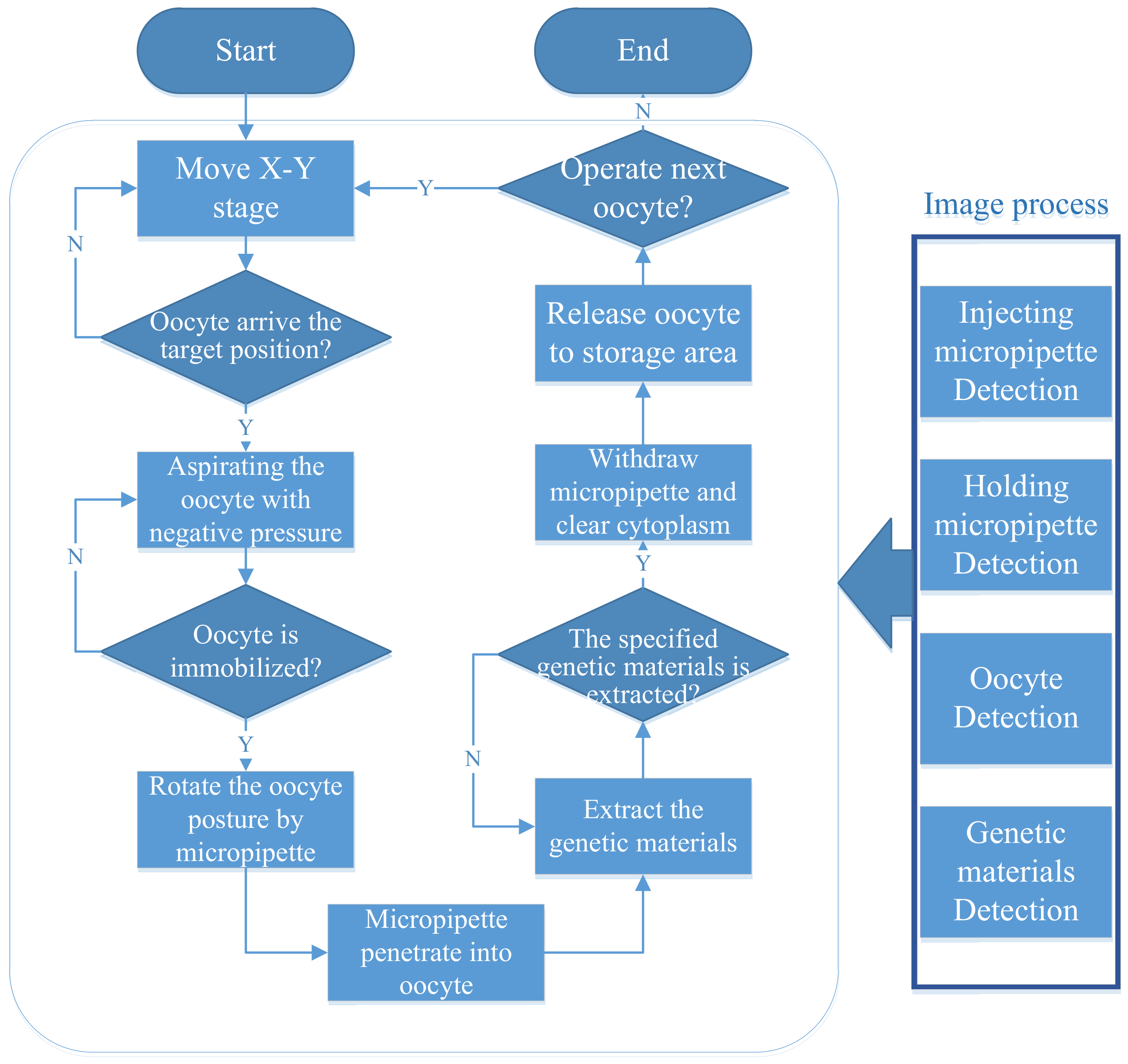
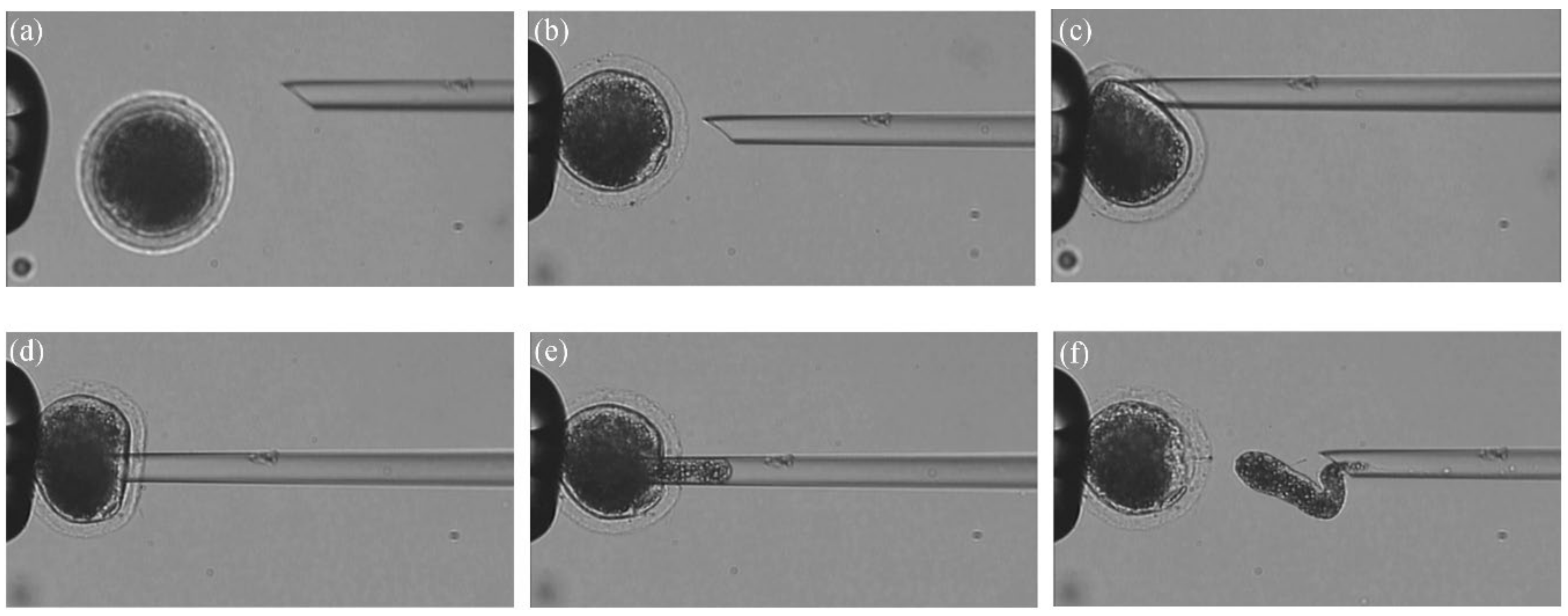
2.1. Process of Robotic Enucleation
- Step 1:
- Place oocytes into the medium culture before conducting the experiment.
- Step 2:
- Move the motorized stage to the operation field until the oocyte to be operated on appears in the microscopic field.
- Step 3:
- Translate the selected oocyte to the specified position in front of the HM. Then pick up the oocyte by reducing negative pressure to immobilize the embryo.
- Step 4:
- Transfer the EM to the position close to the oocyte. Change the pose of the oocyte by the EM. The EM rotates the oocyte until the pole body appears at the desired position [25].
- Step 5:
- The EM penetrates into the oocyte along the planned trajectory and extracts the specific volume of genetic material.
- Step 6:
- Withdraw the EM from the oocyte and drain the genetic material out of the enucleation micropipette.
- Step 7:
- Transfer the oocyte to the storage area and release it with positive pressure.
2.2. Key Techniques
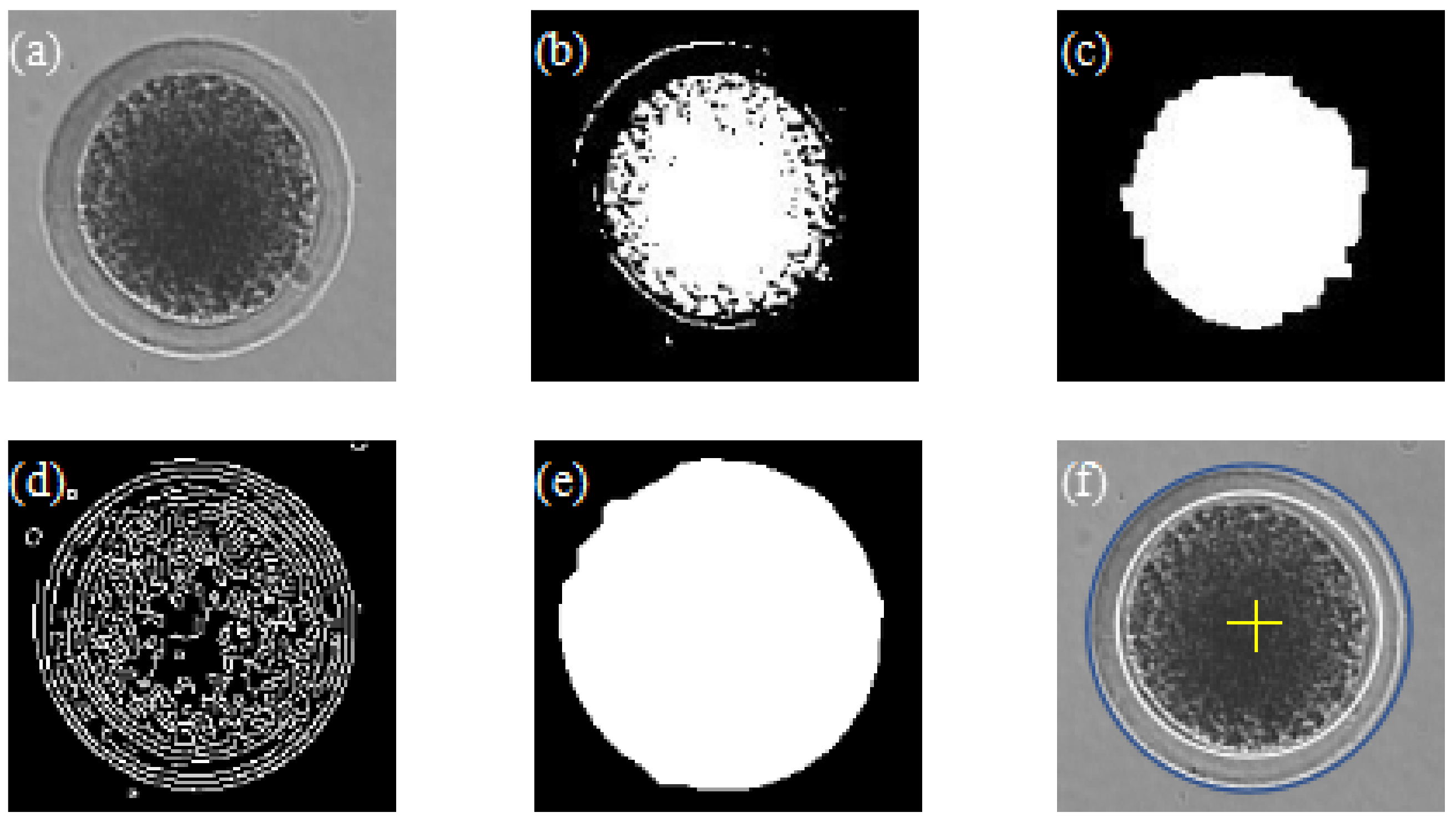
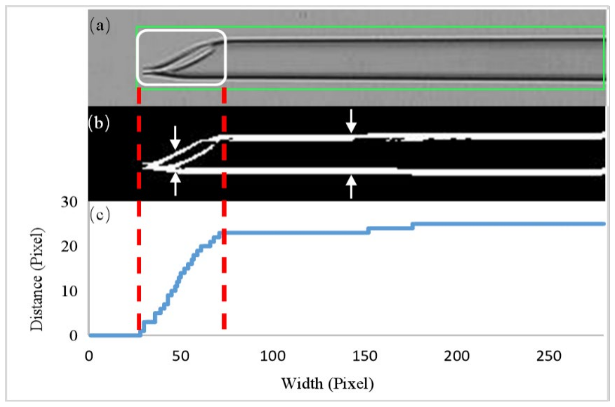
2.2.1. Oocyte and Micropipette Detection
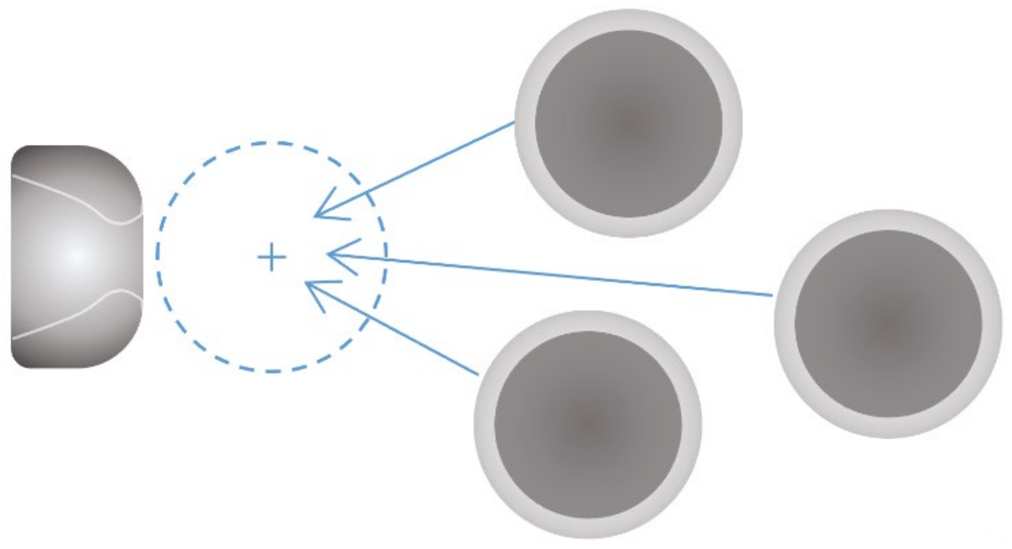
2.2.2. Oocyte Translation Control
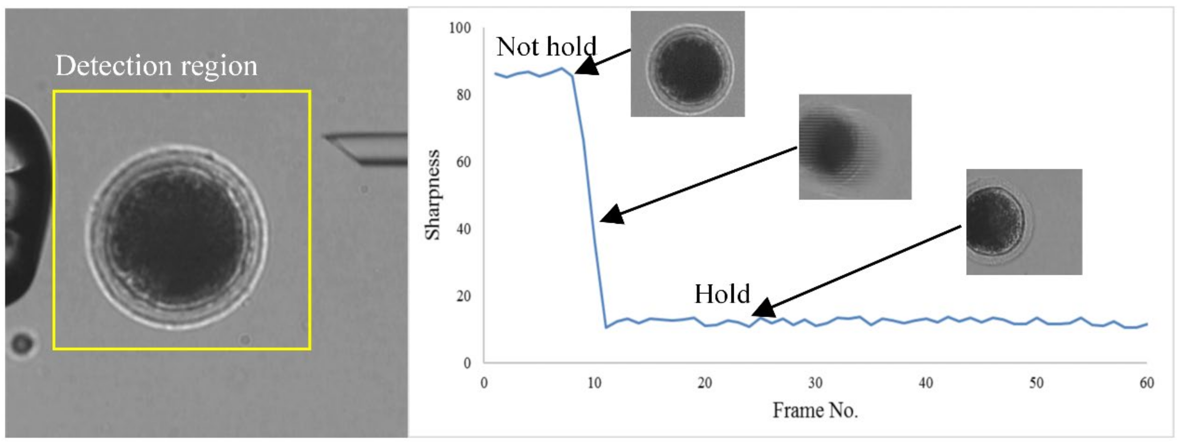
2.2.3. Oocyte Immobilization and Penetration
2.2.4. Enucleation Volume Control Based on Adaptive Slide Mode
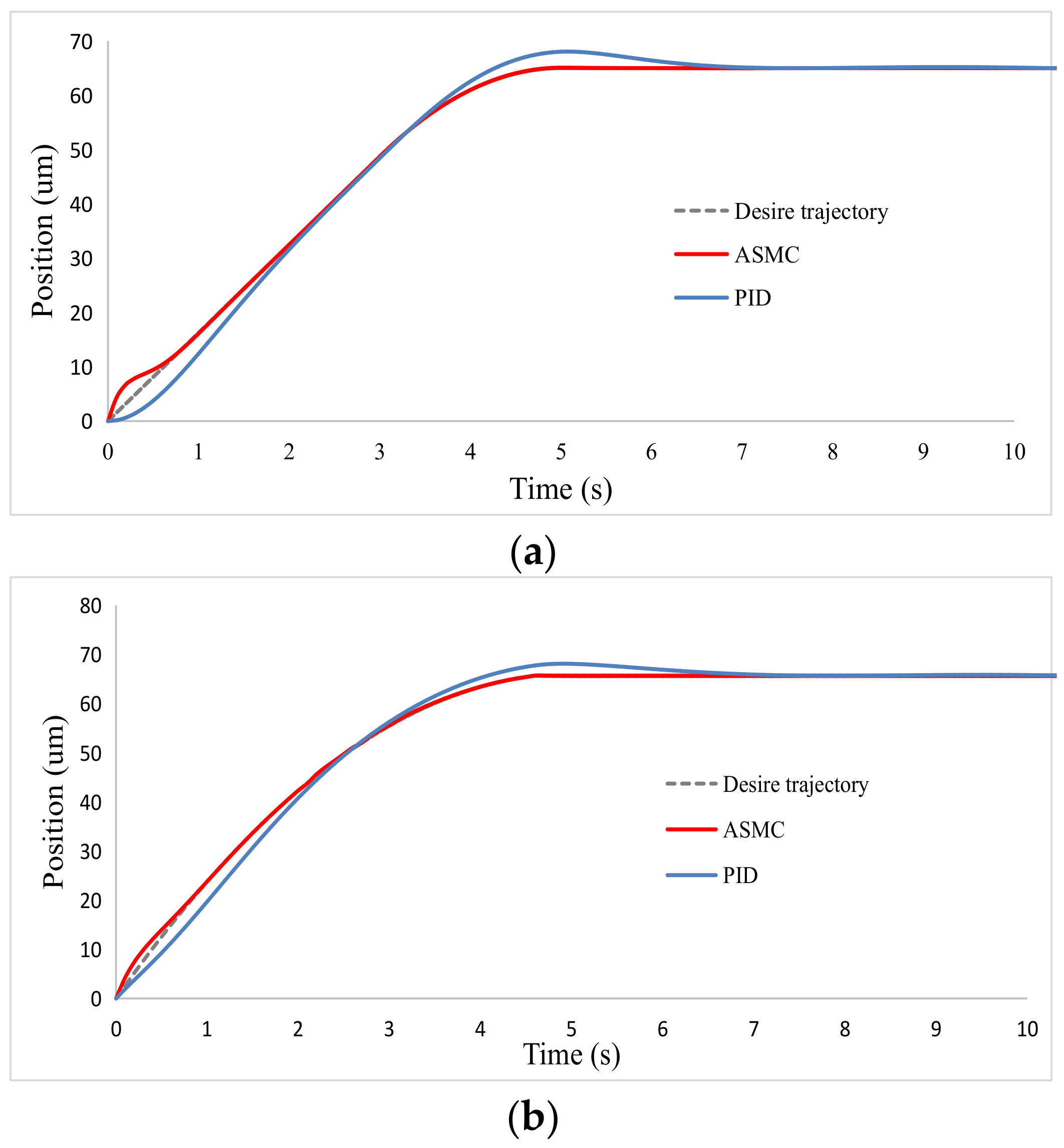
2.3. Controller Simulation
3. Results
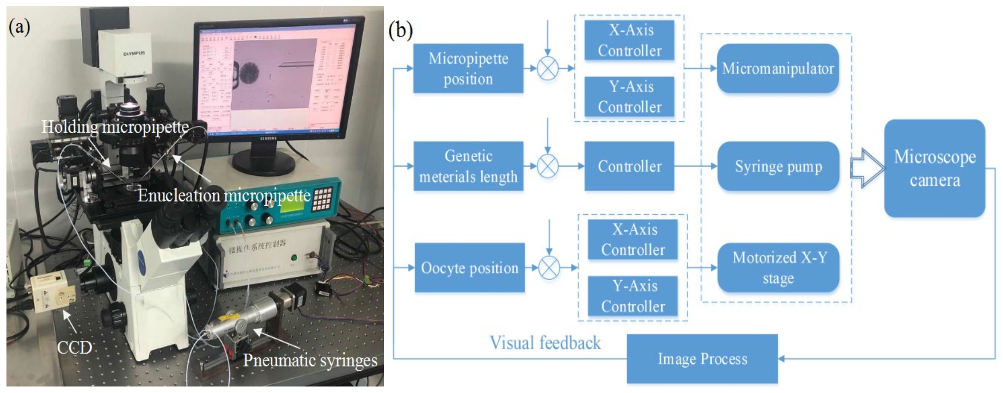
3.1. System Setup
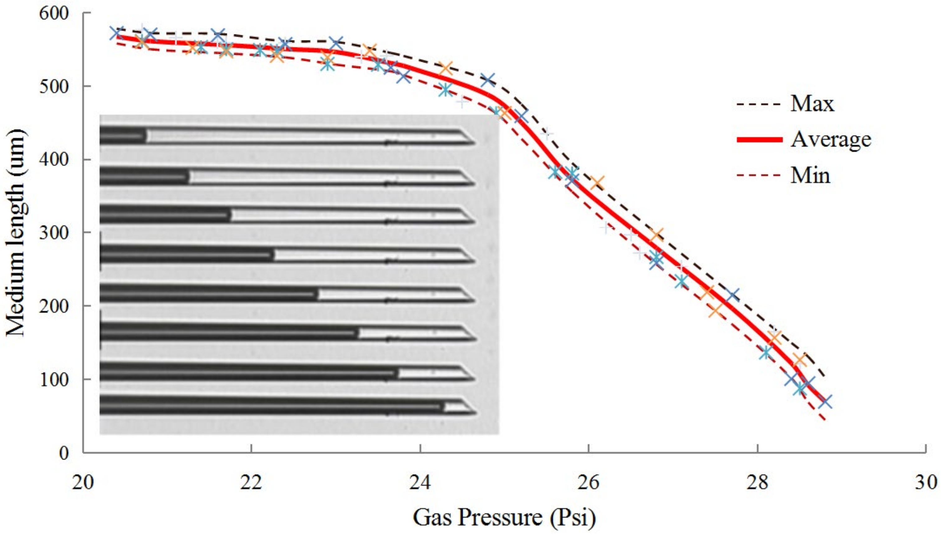
3.2. Enucleation Micropipette Calibration
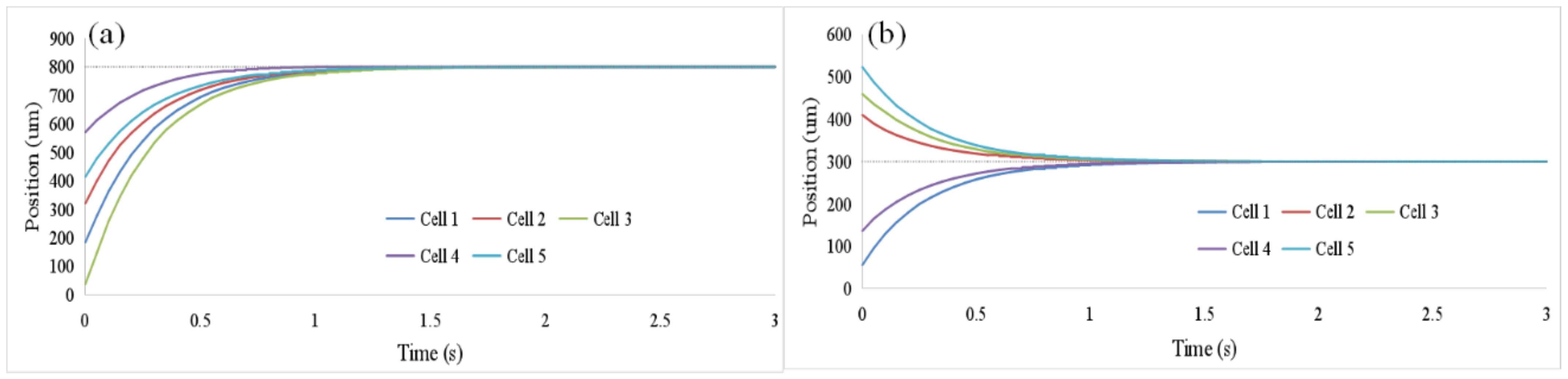
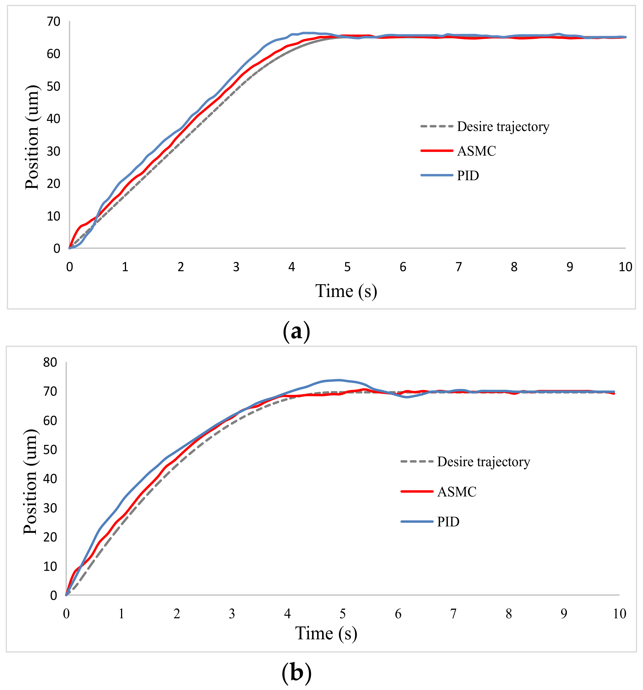
3.3. Oocyte Translation and Enucleation Control Results
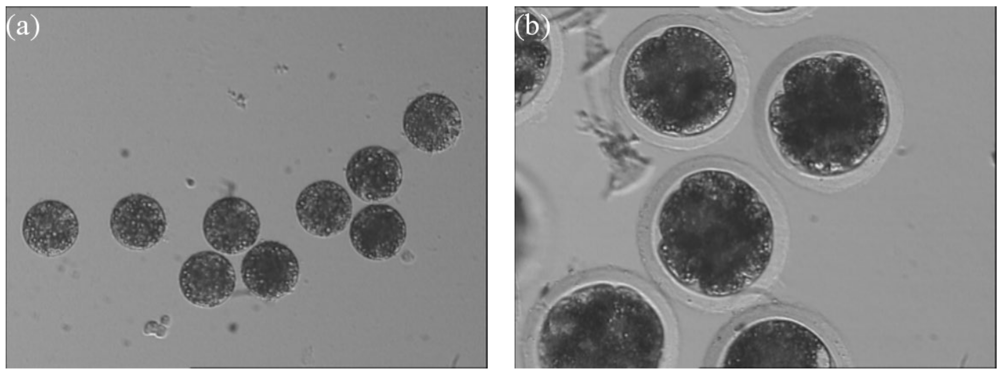
3.4. Enucleation Results
4. Conclusions
Supplementary Materials
Author Contributions
Funding
Institutional Review Board Statement
Informed Consent Statement
Data Availability Statement
Conflicts of Interest
References
- Wilmut, I.; Beaujean, N.; De Sousa, P.A.; Dinnyes, A.; King, T.J.; Paterson, L.A.; Wells, D.N.; Young, L.E. Somatic cell nuclear transfer. Nature 2002, 419, 583–587. [Google Scholar] [CrossRef]
- Wilmut, I.; Schnieke, A.E.; McWhir, J.; Kind, A.J.; Campbell, K.H.S. Viable offspring derived from fetal and adult mammalian cells. Nature 1997, 385, 810–813. [Google Scholar] [CrossRef]
- Cibelli, J.B.; Stice, S.L.; Golueke, P.J.; Kane, J.J.; Jerry, J.; Blackwell, C.; De León, F.A.P.; Robl, J.M. Cloned Transgenic Calves Produced from Nonquiescent Fetal Fibroblasts. Science 1998, 280, 1256–1258. [Google Scholar] [CrossRef] [PubMed]
- Wakayama, T.; Perry, A.C.F.; Zuccotti, M.; Johnson, K.R.; Yanagimachi, R. Full-term development of mice from enucleated oocytes injected with cumulus cell nuclei. Nature 1998, 394, 369–374. [Google Scholar] [CrossRef]
- Chesné, P.; Adenot, P.G.; Viglietta, C.; Baratte, M.; Boulanger, L.; Renard, J.-P. Cloned rabbits produced by nuclear transfer from adult somatic cells. Nat. Biotechnol. 2002, 20, 366–369. [Google Scholar] [CrossRef]
- Galli, C.; Lagutina, I.; Crotti, G.; Colleoni, S.; Turini, P.; Ponderato, N.; Duchi, R.; Lazzari, G. A cloned horse born to its dam twin—A birth announcement calls for a rethink on the immunological demands of pregnancy. Nature 2003, 424, 635. [Google Scholar] [CrossRef]
- Kuwayama, H.; Tanabe, Y.; Wakayama, T.; Kishigami, S. Birth of cloned mice from vaginal smear cells after somatic cell nuclear transfer. Theriogenology 2017, 94, 79–85. [Google Scholar] [CrossRef] [PubMed]
- Lee, S.; Zhao, M.; No, J.; Nam, Y.; Im, G.-S.; Hur, T.-Y. Dog cloning with in vivo matured oocytes obtained using electric chemiluminescence immunoassay-predicted ovulation method. PLoS ONE 2017, 12, e0173735. [Google Scholar] [CrossRef] [PubMed]
- Liu, Z.; Cai, Y.; Wang, Y.; Nie, Y.; Zhang, C.; Xu, Y.; Zhang, X.; Lu, Y.; Wang, Z.; Poo, M.; et al. Cloning of Macaque Monkeys by Somatic Cell Nuclear Transfer. Cell 2018, 174, 245. [Google Scholar] [CrossRef]
- Fan, Z.; Fang, Y.; Sun, M.; Zhao, X. Precise Cell Injection and Extraction Control Based on Microscopic Visual Feedback. IEEE/ASME Trans. Mechatron. 2019, 25, 872–881. [Google Scholar] [CrossRef]
- Huang, H.B.; Sun, D.; Mills, J.K.; Li, W.J.; Cheng, S.H. Visual-Based Impedance Control of Out-of-Plane Cell Injection Systems. IEEE Trans. Autom. Sci. Eng. 2009, 6, 565–571. [Google Scholar] [CrossRef]
- Zhang, Y.; Tan, K.K.; Huang, S. Vision-Servo System for Automated Cell Injection. IEEE Trans. Ind. Electron. 2008, 56, 231–238. [Google Scholar] [CrossRef]
- Yang, H.; Li, X.; Liu, Y.; Sun, D. Automated Transportation of Biological Cells for Multiple Processing Steps in Cell Surgery. IEEE Trans. Autom. Sci. Eng. 2017, 14, 1712–1721. [Google Scholar] [CrossRef]
- Loi, P.; Iuso, D.; Czernik, M.; Ogura, A. A New, Dynamic Era for Somatic Cell Nuclear Transfer? Trends Biotechnol. 2016, 34, 791–797. [Google Scholar] [CrossRef] [PubMed]
- Xie, H.; Zhang, H.; Song, J.; Meng, X.; Wen, Y.; Sun, L. High-Precision Automated Micromanipulation and Adhesive Microbonding With Cantilevered Micropipette Probes in the Dynamic Probing Mode. IEEE/ASME Trans. Mechatron. 2018, 23, 1425–1435. [Google Scholar] [CrossRef]
- Ichikawa, A.; Tanikawa, T.; Matsukawa, K.; Takahashi, S.; Ohba, K. Fluorescent monitoring using microfluidics chip and development of syringe pump for automation of enucleation to automate cloning. In Proceedings of the IEEE International Conference on Robotics and Automation, Kobe, Japan, 12–17 May 2009; pp. 2231–2236. [Google Scholar] [CrossRef]
- Ichikawa, A.; Sakuma, S.; Sugita, M.; Shoda, T.; Tamakoshi, T.; Akagi, S.; Arai, F. On-chip enucleation of an oocyte by untethered microrobots. J. Micromechan. Microeng. 2014, 24, 095004. [Google Scholar] [CrossRef]
- Hagiwara, M.; Kawahara, T.; Feng, L.; Yamanishi, Y.; Arai, F. High Precision Magnetically Driven Microtools with Ultrasonic Vibration for Enucleation of Oocytes. In Proceedings of the International Symposium on Micro-NanoMechatronics and Human Science, Nagoya, Japan, 7–10 November 2010; pp. 47–52. [Google Scholar]
- Feng, L.; Di, P.; Arai, F. High-precision motion of magnetic microrobot with ultrasonic levitation for 3-D rotation of single oocyte. Int. J. Robot. Res. 2016, 35, 1445–1458. [Google Scholar] [CrossRef]
- Inomata, N.; Mizunuma, T.; Yamanishi, Y.; Arai, F. Omnidirectional Actuation of Magnetically Driven Microtool for Cutting of Oocyte in a Chip. J. Microelectromech. Syst. 2011, 20, 383–388. [Google Scholar] [CrossRef]
- Feng, L.; Hagiwara, M.; Ichikawa, A.; Arai, F. On-Chip Enucleation of Bovine Oocytes using Microrobot-Assisted Flow-Speed Control. Micromachines 2013, 4, 272–285. [Google Scholar] [CrossRef]
- Hagiwara, M.; Kawahara, T.; Yamanishi, Y.; Masuda, T.; Feng, L.; Arai, F. On-chip magnetically actuated robot with ultrasonic vibration for single cell manipulations. Lab Chip 2011, 11, 2049–2054. [Google Scholar] [CrossRef]
- Peura, T.; Lewis, I.; Trounson, A. The effect of recipient oocyte volume on nuclear transfer in cattle. Mol. Reprod. Dev. 1998, 50, 185–191. [Google Scholar] [CrossRef]
- Wakayama, T.; Yanagimachi, R. Fertilisability and developmental ability of mouse oocytes with reduced amounts of cytoplasm. Zygote 1998, 6, 341–346. [Google Scholar] [CrossRef]
- Zhao, C.; Liu, Y.; Sun, M.; Zhao, X. Robotic Cell Rotation Based on Optimal Poking Direction. Micromachines 2018, 9, 141. [Google Scholar] [CrossRef]
- Wang, Z.; Feng, C.; Ang, W.T.; Tan, S.Y.M.; Latt, W.T. Autofocusing and Polar Body Detection in Automated Cell Manipulation. IEEE Trans. Biomed. Eng. 2016, 64, 1099–1105. [Google Scholar] [CrossRef]
- Zhao, Q.; Wu, M.; Cui, M.; Qin, Y.; Yu, J.; Sun, M.; Zhao, X.; Feng, X. A novel pneumatic micropipette aspiration method using a balance pressure model. Rev. Sci. Instrum. 2013, 84, 123703. [Google Scholar] [CrossRef]
- Wang, X.; Zhao, Q.; Wang, L.; Liu, J.; Pu, H.; Xie, S.; Ru, C.; Sun, Y. Effect of Cell Inner Pressure on Deposition Volume in Microinjection. Langmuir 2018, 34, 10287–10292. [Google Scholar] [CrossRef] [PubMed]
- Liu, Y.; Wang, X.; Zhao, Q.; Zhao, X.; Sun, M. Robotic Batch Somatic Cell Nuclear Transfer Based on Microfluidic Groove. IEEE Trans. Autom. Sci. Eng. 2020, 17, 2097–2106. [Google Scholar] [CrossRef]
- Liu, Y.; Cui, M.; Huang, J.; Sun, M.; Zhao, X.; Zhao, Q. Robotic Micropipette Aspiration for Multiple Cells. Micromachines 2019, 10, 348. [Google Scholar] [CrossRef]
- Liu, Y.; Cui, M.; Sun, Y.; Feng, Z.; Bai, Y.; Sun, M.; Zhao, Q.; Zhao, X. Oocyte orientation selection method based on the minimum strain position in the penetration process. J. Appl. Phys. 2019, 125, 154701. [Google Scholar] [CrossRef]
- Zhao, Q.; Qiu, J.; Feng, Z.; Du, Y.; Liu, Y.; Zhao, Z.; Sun, M.; Cui, M.; Zhao, X. Robotic Label-free Precise Oocyte Enucleation for Improving Developmental Competence of Cloned Embryos. IEEE Trans. Biomed. Eng. 2020, 1. [Google Scholar] [CrossRef]
- Zhao, Q.; Shirinzadeh, B.; Cui, M.; Sun, M.; Liu, Y.; Zhao, X. A novel cell weighing method based on the minimum immobilization pressure for biological applications. J. Appl. Phys. 2015, 118, 044301. [Google Scholar] [CrossRef]
- Feng, Z.; Zhao, Q.; Liu, Y.; Sun, M.; Zhao, X.; Cui, M.; Zhao, X. Augmented Reality-Based Precise Oocyte Enucleation. In Proceedings of the IEEE 19th International Conference on Nanotechnology (IEEE-NANO), Macao, China, 22–26 July 2019; pp. 530–534. [Google Scholar] [CrossRef]


| Method | Average Time (s) | Accuracy (Standard Deviation) | Success Rate | Cleavage Rate |
|---|---|---|---|---|
| Manual method | 62 | 30.7 | 80% | 41.7% |
| Proposed method | 34.4 | 5.2 | 93.3% | 63.3% |
Publisher’s Note: MDPI stays neutral with regard to jurisdictional claims in published maps and institutional affiliations. |
© 2021 by the authors. Licensee MDPI, Basel, Switzerland. This article is an open access article distributed under the terms and conditions of the Creative Commons Attribution (CC BY) license (http://creativecommons.org/licenses/by/4.0/).
Share and Cite
Zhao, X.; Cui, M.; Zhang, Y.; Liu, Y.; Zhao, X. Robotic Precisely Oocyte Blind Enucleation Method. Appl. Sci. 2021, 11, 1850. https://doi.org/10.3390/app11041850
Zhao X, Cui M, Zhang Y, Liu Y, Zhao X. Robotic Precisely Oocyte Blind Enucleation Method. Applied Sciences. 2021; 11(4):1850. https://doi.org/10.3390/app11041850
Chicago/Turabian StyleZhao, Xiangfei, Maosheng Cui, Yidi Zhang, Yaowei Liu, and Xin Zhao. 2021. "Robotic Precisely Oocyte Blind Enucleation Method" Applied Sciences 11, no. 4: 1850. https://doi.org/10.3390/app11041850
APA StyleZhao, X., Cui, M., Zhang, Y., Liu, Y., & Zhao, X. (2021). Robotic Precisely Oocyte Blind Enucleation Method. Applied Sciences, 11(4), 1850. https://doi.org/10.3390/app11041850