Article

Simple Approach for Evaluation of Abrasive Mixing Efficiency for Abrasive Waterjet Rock Cutting

1
Deep Subsurface Research Center, Geologic Environment Division, Korea Institute of Geoscience and Mineral Resources (KIGAM), Daejeon 34132, Korea
2
Department of Civil Engineering, Pusan National University (PNU), Busan 46241, Korea
3
Department of Civil and Environmental Engineering, Korea Advanced Institute of Science and Technology (KAIST), Daejeon 34141, Korea
*
Author to whom correspondence should be addressed.
Appl. Sci. 2021, 11(4), 1543; https://doi.org/10.3390/app11041543
Submission received: 12 January 2021 / Revised: 31 January 2021 / Accepted: 5 February 2021 / Published: 8 February 2021
(This article belongs to the Section Civil Engineering)

Abstract

:
The abrasive mixing variables, such as the abrasive and water flow rates and the focus geometry parameters, determine the profitability of an abrasive waterjet system. In this study, the mixing efficiency characteristics in abrasive waterjet rock cutting were investigated. To demonstrate comprehensively the efficiency reduction due to collision during abrasive mixing, the chance of collision was expressed as the distance between the abrasive particles in the focus. The mixing efficiency was then assessed by utilizing the empirical relationship between the experimental results and the developed model. Based on the particle density and the velocity, the closer particles showed higher chances of collision, thus yielding a reduced cutting performance. Using the distance between particles model, the optimum abrasive flow rate and the cutting performance of abrasive waterjet systems can be estimated. This developed model can be used for the design selection of abrasive flow rate and systems for the cost-effective use of abrasive waterjets.

1. Introduction

Abrasive waterjets are used to cut target materials using high-velocity abrasives by accelerating them with high-pressure and high-velocity water. Although such waterjets are mainly used for cutting metals and ceramics, their geotechnical applications such as rock cutting, excavation, asphalt resurfacing, pavement adhesion improvement, and road stripe removal have recently increased [1,2,3]. In particular, since the cutting force can be controlled, it is possible to demolish concrete without damaging the internal steel reinforcement [4,5]. In addition, abrasive waterjets are suitable for urban construction because of their low noise and vibration compared to those in mechanical excavation (e.g., rock blasting and breaking). However, the cost of the abrasive reaches approximately 60% of the total operation cost [6]. Efforts have been made to evaluate the effects of the abrasive waterjet parameters on the cost [7,8,9] and to recycle abrasives after recollection and drying [10,11]. The abrasive cost can be reduced by using the optimum abrasive flow rate (AFR) and by using a system design with a high mixing efficiency. The optimum AFR has been estimated at the maximum cutting rate. If 80% of the maximum cutting rate is achieved with 50% of the optimum AFR, the economical AFR is 50% of the optimum AFR.
The cutting energy of an abrasive waterjet is a function of the AFR, and the system design determines its characteristics [12,13]. The optimum AFR is a function of the impact frequency, the terminal velocity, and the kinetic energy of the abrasive through the relationship between the mixing efficiency and energy [14,15]. Meanwhile, optimizing the focus shape improves the mixing efficiency, where the momentum of the water is transferred to the abrasive [16]. In principle, the length and diameter of the focus at which the abrasive is mixed are the main mixing and acceleration variables that affect the cutting energy and the optimum AFR [17,18,19]. In other words, an economical system design is achieved through an optimal combination of focus length, focus diameter, and orifice diameter [20]. Therefore, evaluation of the mixing variables is required to enable mixing efficiency adjustment. The focus keeps the abrasive in the water jet during acceleration, but abrasive friction with the inner surface of the focus and abrasive particle collisions reduce the mixing efficiency [19]. Abrasive experience breakdown (i.e., disintegration) is caused by friction and collisions [21]. Abrasive breakdown increases with increasing pump pressure, AFR, or focus length [11]. These relations indicate that the abrasives are involved in the damping mechanics depending on the abrasive density in the focus [19,22]. The water flow rate (WFR)–AFR ratio and the focus geometry (e.g., diameter and length) affect the abrasive breakdown, thereby reducing the abrasive mixing efficiency. Thus, AFR and waterjet system optimization begins by determining the characteristics of the mixing variables (e.g., WFR, AFR, and focus geometry). The orifice diameter and pump pressure determine the WFR [23], and the focus diameter and WFR are major factors affecting the cutting quality [17]. The larger the focus diameter, the larger the jet diameter, which affects the groove frequency and striation on the cutting surface, resulting in large changes in the surface profile amplitude [24]. Analysis of variance on the effects of the focus and orifice has shown that 98% of the cutting width and roughness results from the focus diameter and the AFR [18,25,26]. The abrasive mixing efficiency is the characteristic that is the most strongly affected by the AFR, and the larger the focus diameter, the higher the optimum AFR [15]. Moreover, the larger focus diameter reduces the energy that accelerates the abrasive [27]. As a result of evaluating the overall effects of the WFR and focus diameter, the economically optimum ratio between the orifice and focus diameter was determined to be three times [28]. Table 1 summarizes the literature on the effects of the focus geometry, the AFR, and the WFR on an abrasive waterjet.
The mixing efficiency of an abrasive is determined by the abrasive–abrasive and abrasive–focus inner surface collisions. However, studies that comprehensively demonstrate the characteristics of the mixing efficiency considering the WFR, the AFR, and the focus diameter simultaneously are scarce. Under ideal mixing and acceleration, the abrasive is completely surrounded by water and accelerated without interference. Figure 1 provides a conceptual illustration of abrasive acceleration, showing the characteristics of the mixing variables. The AFR and the focus diameter affect the chance of collision as a function of the abrasive density in the focus. The WFR and the AFR determine the mixing time for which the abrasive remains in the focus because it determines the abrasive velocity. The longer the abrasive remains in the focus, the higher the collision frequency. Thus, the effects of the mixing variables on the geometric behavior of the abrasive were expressed. The distance between particles (DBP) in the focus can represent the mixing efficiency as a function of the collision chance. Figure 2 shows the characteristics of the DBP and mixing variables. As the AFR increases, the DBP decreases (e.g., DBP1–DBP2). As the focus diameter or WFR increases, the DBP increases (e.g., DBP2–DBP3 and DBP3–DBP4). A high DBP means that the abrasive particles are far from each other, so the chance of collision is low and the mixing efficiency is high. As such, the intuitive characteristics of the abrasive mixing efficiency can be expressed in terms of the DBP. In addition, because the concept of space occupied by a single particle was introduced to define the space in which the abrasives independently remain, not only abrasive–abrasive collisions but also abrasive–focus collisions can be considered.
In this study, the mixing variables, developed using a theoretical model of the DBP, were experimentally evaluated, and the mixing efficiency was estimated based on the relationship between the rock cutting rate and the DBP. Through a parametric study of the developed model, the effects of the mixing variables were reviewed across wide ranges of the variables. The developed model using the DBP can intuitively represent the effects of the mixing variables. Using this model, the cutting performance can be predicted through the relationship between the input energy and the mixing efficiency, and the optimum AFR can be estimated. This approach can be employed for AFR and waterjet system design selection for low cost and high efficiency.

2. Abrasive in the Focus

2.1. Number of Abrasive Particles in the Focus

Based on Bernoulli’s principle, high-pressure water produced by a pump reaches a high velocity as it exits the narrow inlet of an orifice [29]. Considering the energy loss as the resistance constant (K), which is affected by the orifice size and shape, the initial water velocity ( v w , 0 ) can be expressed as follows [23,30]:
v w , o =   ( 1 K ) 2 g γ p w ,
where g is the gravitational acceleration, γ is the unit weight of water, and p w is the pressure of the pump-generated water. The resistance constant is about 0.25 and 0.5 for square and sharp edges, respectively, and ranges from 0.04 to 0.28 for rounded orifices. A typical orifice has a square edge shape [31,32].
After the high-velocity water is generated, the abrasive is injected. When the abrasive accelerates, the momentum of the water is transferred to the abrasives according to the momentum balance and continuity equation for water and solid flow, which increases the momentum of the abrasives accordingly [23,33]. This approach, which utilizes water and abrasive mass, can be applied to calculate the equation for inputting energy. The exit velocity (velocity at which the abrasive leaves the focus after mixing) and acceleration of the abrasive are affected by the size and density of the abrasive. However, for easy and general calculation, the terminal velocity ( v t ) at which the velocities of the water and the abrasive become theoretically equal is considered as the abrasive velocity and is calculated as follows [34,35,36]:
m ˙ w v w , o t o = m ˙ w v w t o + m ˙ a v a t o = ( m ˙ w + m ˙ a ) v t t o ,
where v w and v a are the velocities of the water and the abrasive, respectively; t o is the operating time (i.e., time for which the abrasive is injected); m ˙ w is the water flow rate; and m ˙ a is the AFR.
The abrasive is accelerated and mixed in the mixing chamber or the focus. During mixing, the mixing efficiency varies depending on the mixing variables such as the water flow rate ( m ˙ w ), the AFR ( m ˙ a ), and the focus geometry. The mixing efficiency is expressed by the momentum transfer parameter ( η t ), which is the most influenced by the AFR (Cha et al. 2020). The terminal velocity ( v t ) considering the momentum transfer parameter is expressed as [31,37]:
v t = η t v w , o 1 + ( m ˙ a / m ˙ w ) .
Theoretically, the velocities of the abrasive and water reach the terminal velocity during the early phase of acceleration. The abrasive travels most of the time inside the focus at terminal velocity. The mixing time ( t f ) is the time for which the abrasive is accelerated and mixed in the focus. In other words, the time taken for the abrasive to exit the focus can be expressed as follows in terms of the focus length ( l f ) and terminal velocity:
t f = l f / v t .
Substituting Equation (3) into Equation (4), the total number of abrasive particles in unit time ( N p , f ) can be obtained as:
N p , f = m ˙ a t f / m p = m ˙ a ( 1 + m ˙ a / m ˙ w ) l f / m p η t v w , o ,
where, m p is the mass of a single abrasive particle.

2.2. Distance between Abrasive Particles in the Focus

In the focus, the abrasive particles move and are independently located in each space, as shown in Figure 1. The volume occupied by a single particle ( V s ) depends on the volume inside the focus ( V f o c u s ) and the total number of abrasives within the focus ( N p , f ):
V s = V f o c u s / N p , f = π 4 d f 2 l f m p / m ˙ a t f ,
where d f is the focus diameter and l f is the focus length.
Assuming that the abrasives are uniformly distributed and are spherical-shaped with a volume V s , they are all circumscribed. Thus, the distance between the centers of V s is the diameter of V s . Considering the abrasive diameter ( d p ), the DBP becomes:
DBP = V s · 6 / π 3 d p .
Substituting Equation (6) into Equation (7), the DBP in the focus is represented by the AFR, the focus geometry, the abrasive diameter and mass, and the terminal velocity, as follows:
DBP = 3 2 d f 2 l f m p / m ˙ a t f 3 d p .
The main energy of the abrasive waterjet for material removal comes from the accelerated abrasive particles. In terms of the AFR and the terminal velocity, the kinetic energy of the abrasive per second ( E a ) can be expressed as:
E a = 1 2 m ˙ a v t 2 .
Based on kinetic energy per unit second ( E a ) and cutting depth ( D ), the energy required to cut a unit depth ( ε ) as a function of the DBP is assumed to be:
E a / D = ε = α ( DBP ) β ,
where α and β are an empirically determined constant and an exponent, respectively, and ε is the energy required to cut one unit depth of rock.
The cutting depth is affected by the mixing efficiency. As shown in Equation (8), it is possible to demonstrate the relationship between the kinetic energy removal and the experimental results in consideration of the focus geometry, the AFR, and the WFR. This model can also be expressed by the pump pressure using Equation (1). Through this study, the mixing variables can be expressed comprehensively. This model defines the energy in unit time, rather than the mixing time t f , to intuitively show the mass and velocity of the abrasive. At a high AFR, the kinetic energy decreases as the terminal velocity decreases, whereas t f increases. However, a limitation of this approach is that the ideal case of abrasive-fluid behavior is assumed in the developed model. The mixing is greatly affected by the turbulent flow, the viscosity of the fluid, and the physical properties of the abrasive as well as collision and friction. Therefore, the empirical relationship between the simple theoretical approach and the experimental results is shown in this study. Eventually, further studies regarding the effect of geometrical and frictional loss of both water and abrasive within the focus are required to overcome this limitation.

3. Experimental Program

3.1. Test Cases and Setup

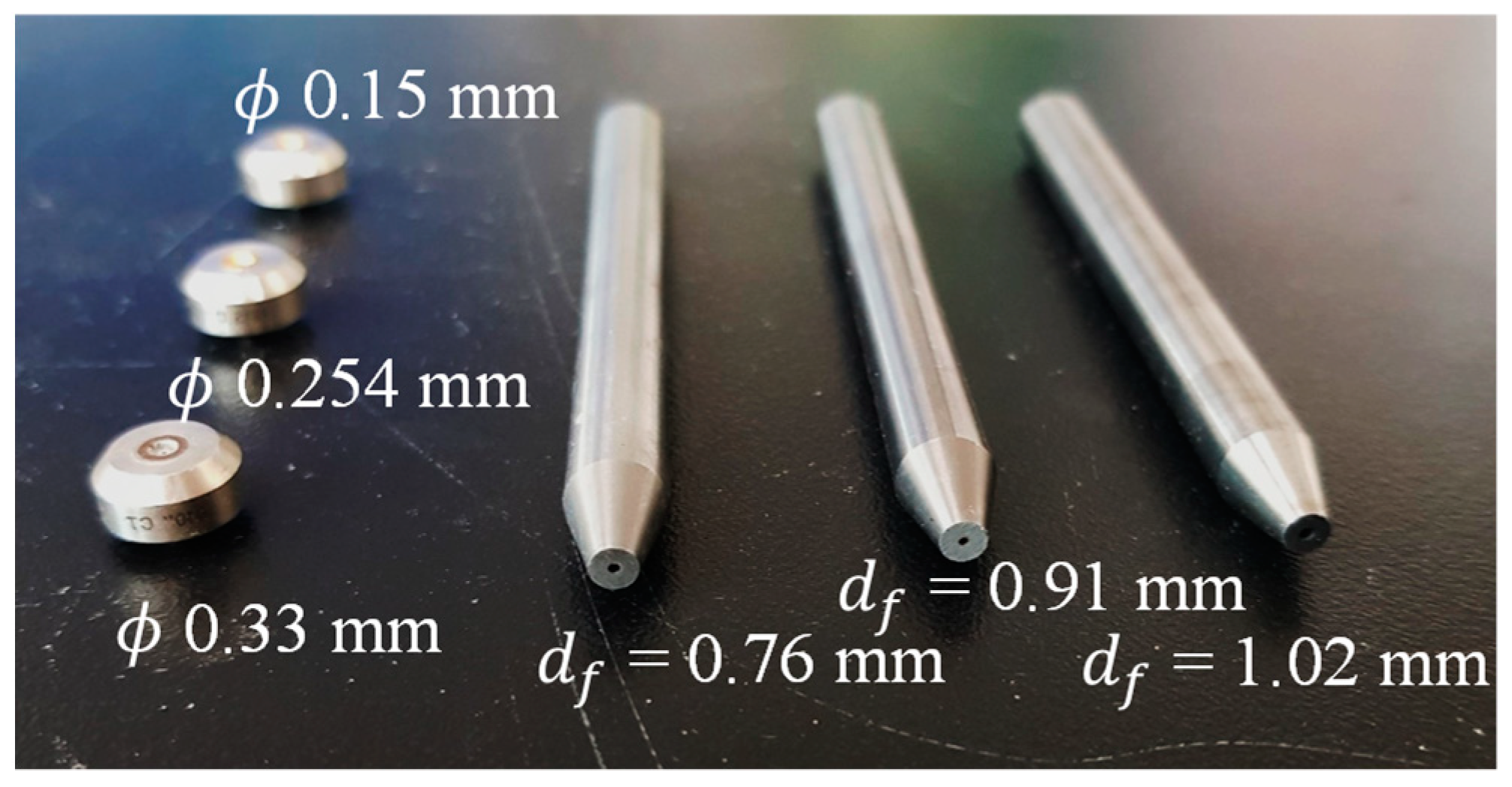
To evaluate the mixing efficiency and cutting performance according to the DBP in the focus, the main variables used were the focus diameter, the orifice diameter, and the AFR. The focus diameter and the terminal velocity of the abrasive were controlled. To evaluate these variables considering the applicability, commercial product sizes, which are popular in the waterjet industry, were used. Figure 3 shows the orifices and focuses used in the experiment. Sapphire orifices with diameters of 0.15, 0.254, and 0.33 mm and WFRs of 10.67, 29.50, and 50.00 mL/s were utilized at a pressure of 320 MPa. For each WFR, tungsten carbide focuses with diameters of 0.76, 0.91, and 1.02 mm were employed. The AFR was controlled by Venturi suction according to the WFR and pressure from a minimum of 3.3 g/s to a maximum of 29 g/s. Table 2 lists the details of the experimental cases, including the WFR, the AFR, and the focus diameter.
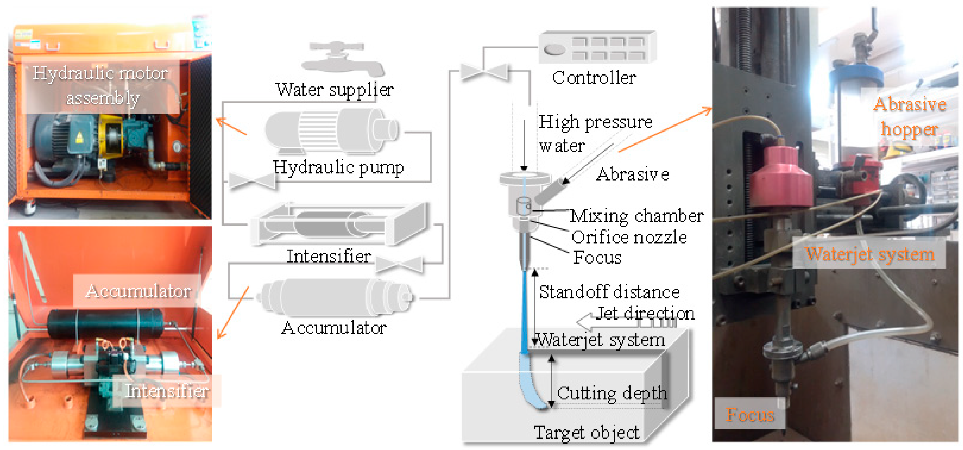
An abrasive injection waterjet (AWJ) consists of a pump section and an abrasive waterjet system. Figure 4 depicts the intensifier pump and the abrasive waterjet system used in the experiment. The pump capacity used was 50 HP of hydraulic power and the waterjet could produce 6 mL/s of water with a maximum pressure of 420 MPa. In a suspension waterjet (slurry waterjet; SWJ), a high-pressure pump applies pressure to a mixture of water and abrasive, whereas in an AWJ, which was used in this study for rock cutting, the pump applies pressure only to the water and the water accelerates the abrasive. AWJs are more suitable for civil engineering purposes, such as rock excavation, because the system is relatively simple and occupies a small space.

3.2. Abrasive and Rock Specimen

Figure 5a shows the abrasive, pyrope-type Indian garnet. It is composed of Mg3Al2(SiO4)3, and its specific gravity is 3.79. The abrasive particles remaining on the 80th sieve were utilized to ensure a uniform abrasive diameter, as the DBP is affected by the abrasive diameter (Equation (8)). The particle size distribution indicates a mean particle size of 0.18 mm, as shown in Figure 5b [38,39]. Table 3 provides the details of the abrasive.
The rock specimens to be cut were granite with dimensions of 150 × 150 × 300 mm. As granite is the most common rock in Korea, it was selected considering the practical applications of waterjet rock cutting. The granite specimens were quarried at the same depth to ensure uniform physical properties. As shown in Table 4, the uniaxial compressive strength (UCS) of the granite specimen was 236 MPa, the shear strength was 23 MPa, and the tensile strength was 12 MPa; hence, it was classified as very strong rock [40,41]. The specific gravity was 2.65, the absorption ratio related to voids was 0.27%, and the shore hardness was 114.

3.3. Test Procedure

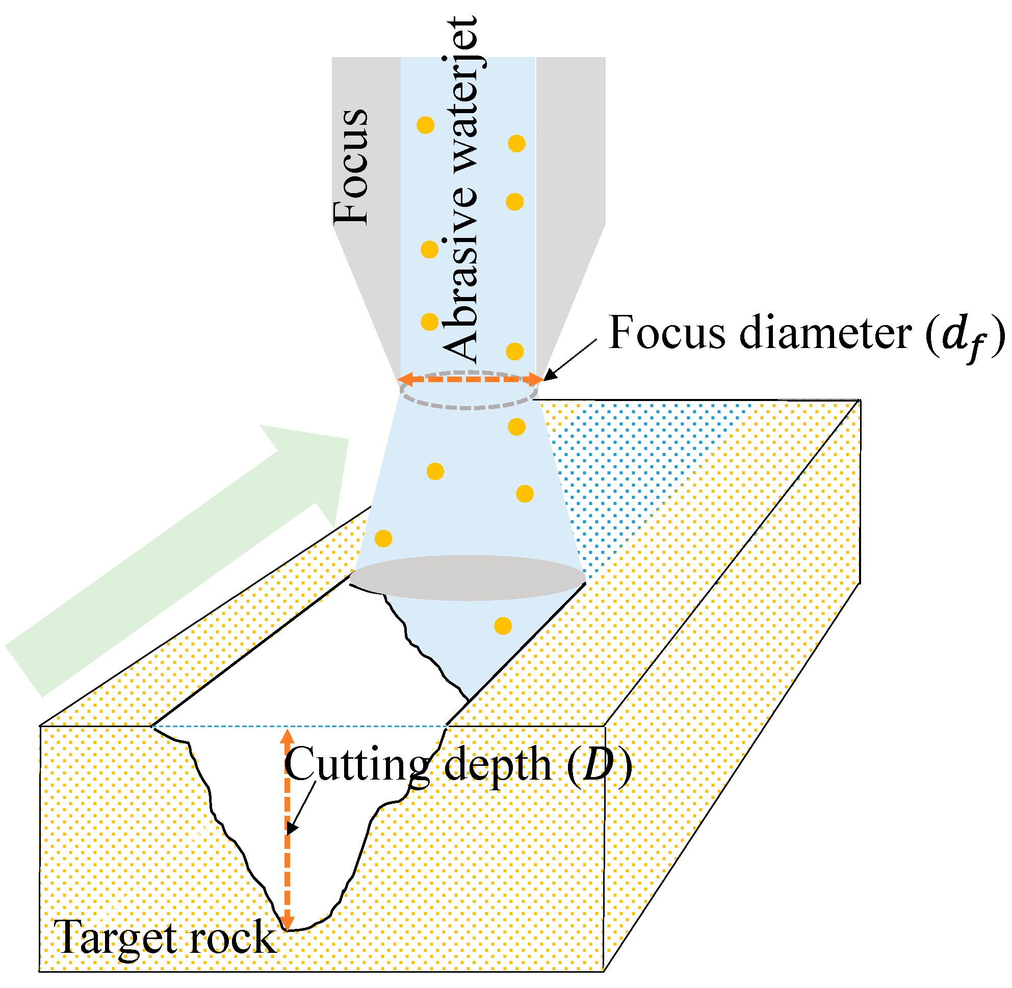
The orifice was located inside the waterjet assembly for withstanding the high-pressure fluid, whereas the focus was simply attached outside. For efficiency, the experiment was streamlined in the order of AFR control, focus change, and orifice change. The AFR error was minimized by measuring the time required to consume 200 g of abrasive at least three times. The rock was cut once in one direction from the outside to the inside of the granite specimen, as shown in Figure 6. The jetting system could move at speeds of 1.2–16 mm/s, and the traversing speed in this experiment was 8.4 mm/s considering back thrust due to high-pressure water flow. The cutting paths in each case were kept at least 70 mm apart to prevent them from influencing or overlapping with each other. The standoff distance (SOD) is the distance between the end of the focus and the specimen. It is the variable that has the greatest influence on the cutting width and dispersion of the abrasive particles; in this experiment, SOD was set very close to 10 mm to minimize its effect. The cutting depth was measured by calibrated calipers at five points from the start to the end along the cutting path, and three measured values excluding the maximum and minimum ones were averaged.

4. Experimental Results and Analysis

4.1. Kinetic Energy and Rock Cutting Performance

Figure 7 depicts a granite specimen after the experiment, along with the focus geometry, the water flow rate, and the AFR. The cutting surface indicates the cutting path, and the cutting side shows the cutting depth at the cutting start point according to the test conditions. Because the SOD is short, the cutting width is similar to that shown on the cutting surface. Figure 8 presents the cutting depth according to the AFR at each WFR for each focus diameter, showing that the larger the focus diameter, the deeper the cutting depth. The maximum cutting depth occurs at a large focus diameter, and the optimum AFR ( m ˙ a , o ), which is the AFR at the maximum cutting depth, increases with the focus diameter. With the same input energy conditions (e.g., water pressure, water, and AFR), the mixing variables affect the cutting depth.
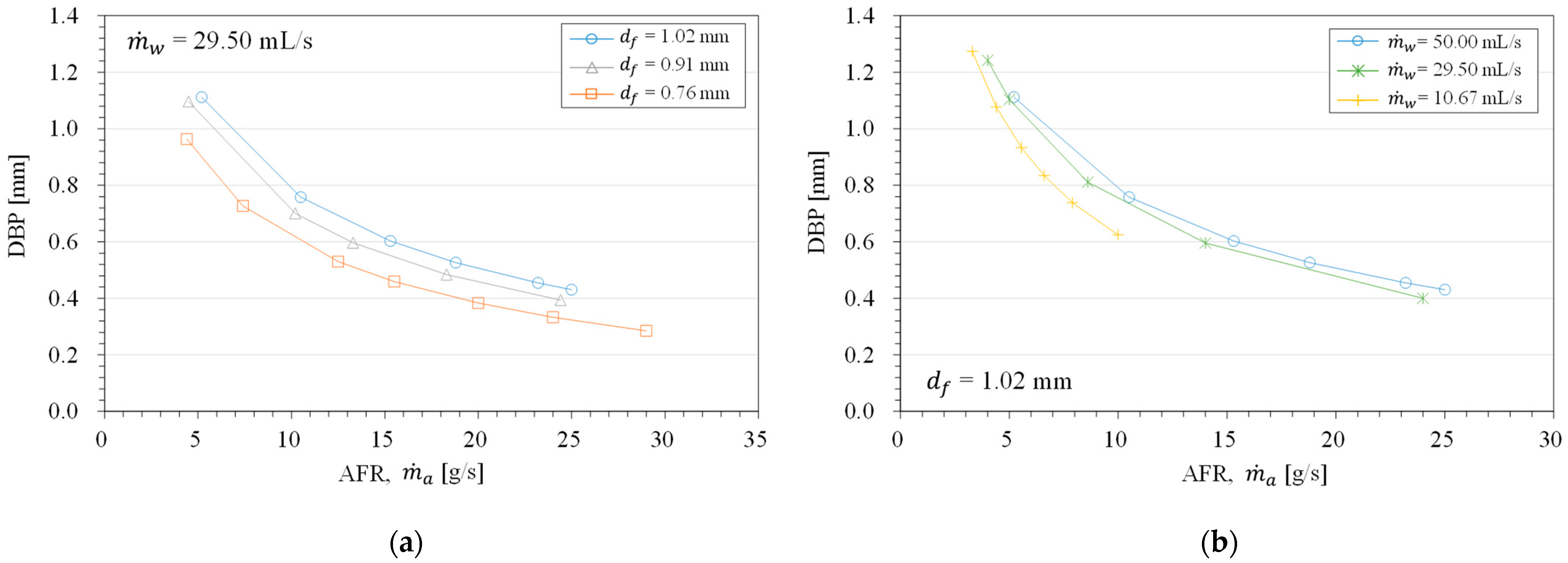
Figure 9 shows the DBP as a function of the AFR by focus diameter. This figure demonstrates that the larger the focus diameter, the farther the abrasives are from each other, resulting in a higher DBP. An increase in the AFR increases the number of abrasive particles in the focus and decreases the DBP (Figure 9a). As derived from Equations (4) and (7), the WFR does not significantly affect the DBP. This finding is explained by the fact that all the abrasive particles are simultaneously accelerated and move at the same velocity. A higher WFR results in a faster initial water velocity (Equation (3)), so the abrasive–water mixture moves faster, but t f decreases. Whether the abrasive particles move quickly or slowly, the DBP remains the same. Because the WFR affects the terminal velocity of the abrasive, a larger WFR has a larger kinetic energy for cutting, even with the same AFR. The complex effect of the mixing variables can be expressed as the energy required to cut one unit depth of rock ( ε ) from the experimental results, as shown in Figure 8.
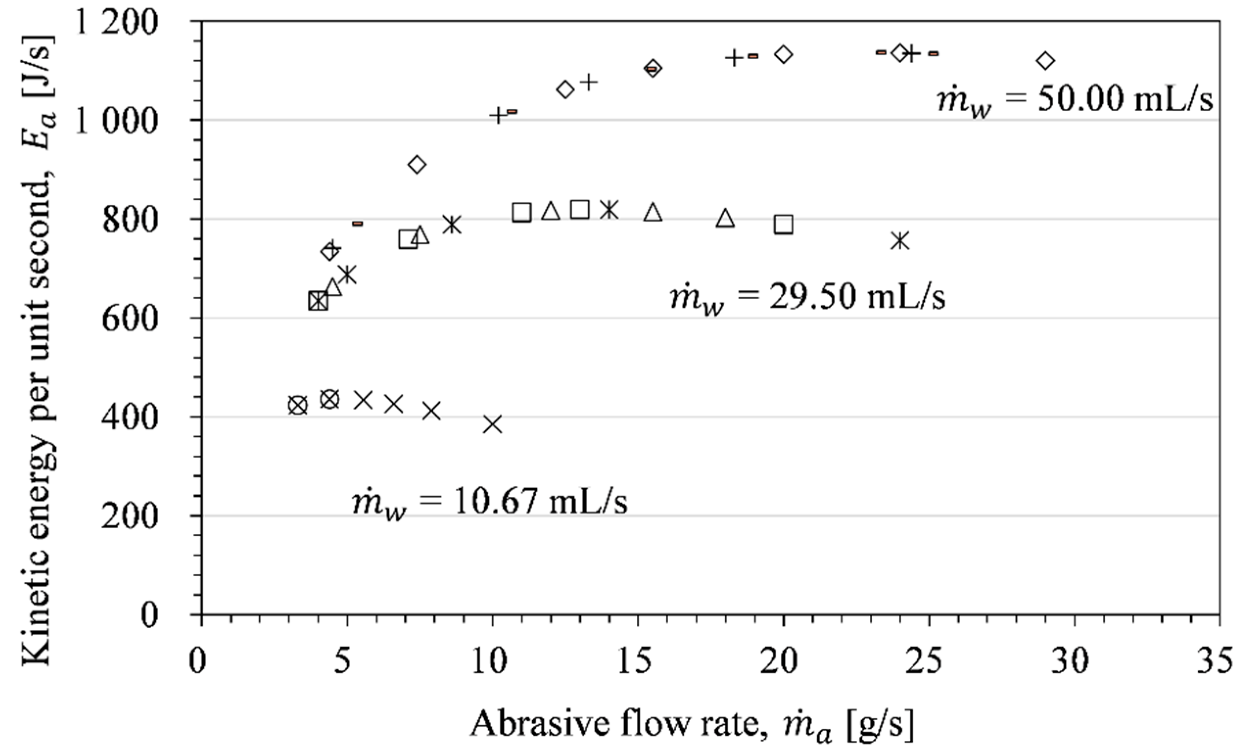
Figure 10 presents the kinetic energy per unit second ( E a ) calculated using Equation (9) under the experimental conditions of this study. A high water flow rate corresponds to a large acceleration momentum, yielding a high kinetic energy because of the high terminal velocity. Increasing the AFR causes an increase in the total abrasive mass but decreases the terminal velocity (Equation (2)). As such, the kinetic energy for rock cutting and the effects of the abrasive mixing variables resulting from the experiment were evaluated using a function of the DBP.

4.2. DBP and Cutting Characteristics

One of the objectives of this study was to identify a comprehensive relationship among variables affecting the mixing and acceleration, such as the water flow rate, the AFR, and the focus diameter. The energy required to cut a unit depth according to the DBP is shown in Figure 11. These results indicate both mixing efficiency and cutting performance. The DBP and energy required to cut a unit depth are correlated with α = 11.595 ± 0.63 and β = 0.738 ± 0.02 in Equation (10). The coefficient of determination is 0.9606, which shows a high goodness of fit and can be expressed as follows:
E a / D = ε = 11.595 · DBP 0.738 .
The colored mark in Figure 11 indicates the optimum AFR ( m ˙ a , o ) based on the WFR. In general, the larger the WFR, the larger the amount of energy required to cut 1 mm, which means that the cutting efficiency is higher at a lower WFR. Based on this result, the DBP corresponding to the optimum AFR at a high WFR was estimated to be less than approximately 0.6 mm. Using the relationship between the energy required to cut one unit depth and the DBP, the optimum AFR can be determined according to the WFR and the waterjet system.
By substituting the energy required to cut one unit depth from Equation (10) and the DBP from Equation (7) into Equation (11), the cut depth can be expressed as follows:
D = m ˙ a v t 2 2 · 11.595 ( 3 2 d f 2 l f m p / m ˙ a t f 3 d p ) 0.738 .
This approach represents the characteristics of mixing variables such as the focus geometry, the abrasive particle diameter, the mass of a single abrasive particle, the AFR, and the water flow rate based on the terminal velocity. The cutting depth can be estimated under a wide range of waterjet system conditions by measuring α and β from three or more points representing the relationship between the energy required to cut one unit depth and the DBP.
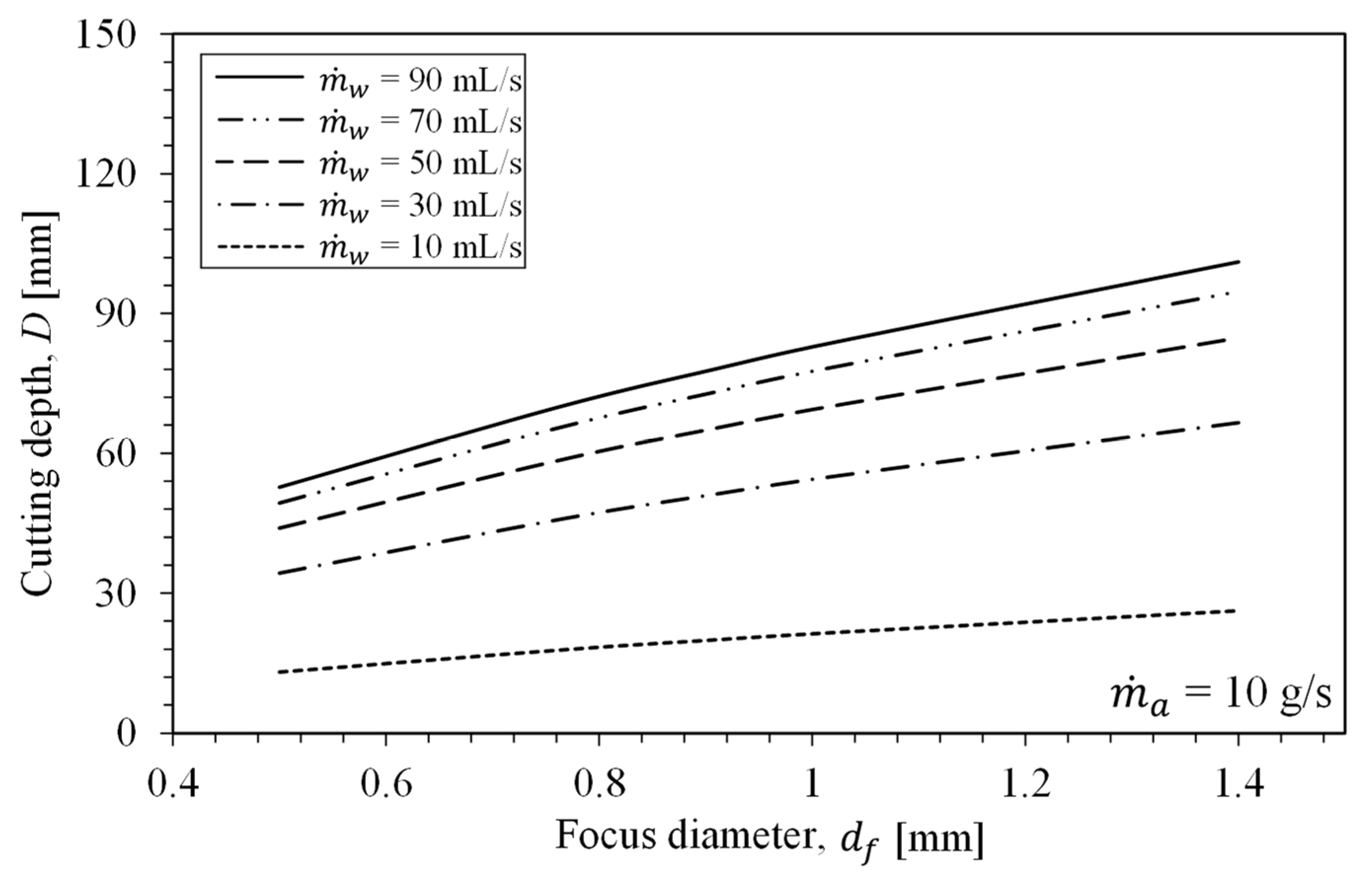
Figure 12 presents the results of a parametric study, depicting the cutting depth with a given water flow rate according to the focus diameter at an AFR of 10 g/s (according to Equation (12)). The mixing variables were evaluated over a wide range, and it was found that the larger the focus diameter, the greater the cut depth. The effect of the focus diameter is larger at higher water flow rates. It can also be demonstrated that a high WFR results in a large reduction in efficiency because of the focus diameter. Increasing the water flow rate from 50 mL/s to 90 mL/s (i.e., by 80%) increases the cutting depth by 20%. Although the maximum cutting depth occurs at 90 mL/s, 50 mL/s of flow rate is considered to be economical. Thus, it is possible to design an economical water flow rate using Equation (12).
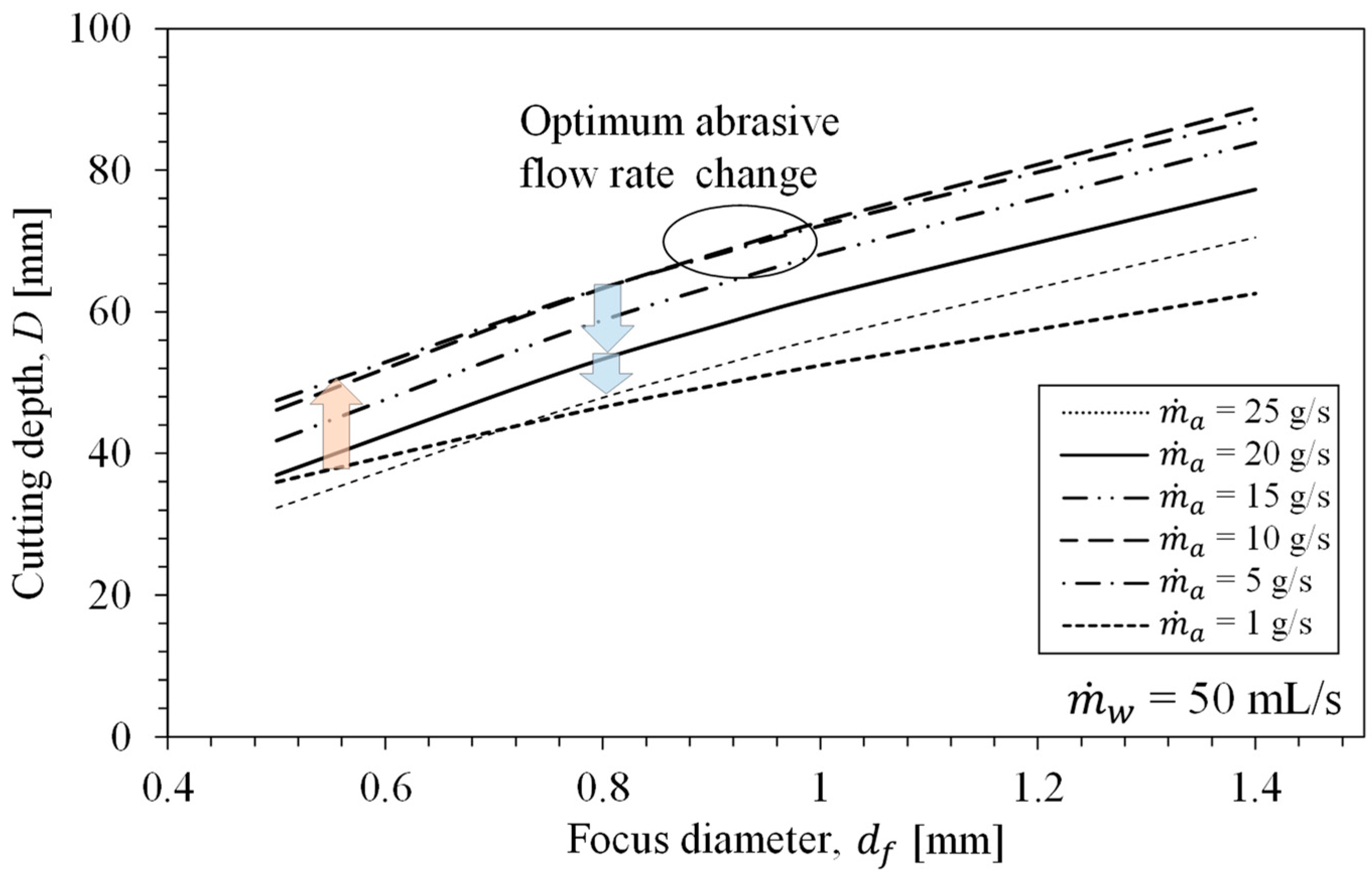
Figure 13 illustrates the results of a parametric study, showing the effect of the focus diameter and the AFR on the cutting depth at a WFR of 50 mL/s. For a focus diameter less than 0.9 mm, the optimum AFR is close to 5 g/s (dashed dotted line), but for a larger diameter focus, the optimum AFR is close to 10 g/s (dashed line). This approach demonstrates the change in the optimum AFR according to the focus diameter. An increase in AFR increases the impact frequency (up arrow) while reducing the terminal velocity and cutting energy (down arrow), as indicated by Equation (3). In addition, a high AFR yields numerous collisions between abrasive particles, reducing the cutting efficiency. This parametric study demonstrates that the DBP in the focus enables optimal design of the focus diameter, the AFR, and the WFR.

5. Conclusions

The purpose of this study was to evaluate the mixing characteristics of abrasive waterjet rock cutting. The dependence of the rock cutting performance on the mixing variables, such as the abrasive flow rate, the water flow rate, and the focus geometry, was experimentally tested. To evaluate the mixing variables comprehensively, the chances of abrasive–abrasive and abrasive–focus inner surface collisions were defined in terms of the DBP in the focus. In addition, as the cutting energy and experimental results were expressed as functions of the DBP, the characteristics of the mixing variables were assessed. The results of this study can be used for geotechnical application such as improved abrasive waterjet rock excavation. The following are the major findings and contributions of this study:
  • The abrasive mixing characteristics were derived based on the mixing variables, such as the WFR, the AFR, and the focus geometry. To express the complex effects of the variables, a mixing efficiency model was developed considering the chance of collision by defining the concept of the DBP, which represents the abrasive density in the focus. This model comprehensively considers the WFR, the AFR, the focus diameter and length, and the abrasive mass and diameter.
  • As a result of the effects of the mixing variables, the cutting depth was experimentally obtained. It was found that using a large focus diameter or water flow rate, a higher mixing efficiency yields a greater cutting depth. The AFR affects the terminal velocity and mixing efficiency, so excessive input reduces the cutting depth. The higher the mixing efficiency, the higher the optimum AFR.
  • By expressing the relationships between the experimental results and input energy as functions of the DBP, the effects of the mixing efficiency on abrasive waterjet rock cutting could be calculated. The smaller the DBP, the higher the energy required to cut a unit depth of the rock. In other words, a high energy input was required owing to the low mixing efficiency.
  • The developed model demonstrated that, with a high water flow rate, the cutting efficiency was low compared to the energy input. In addition, high water flow rates indicated the optimum AFR at small DBPs. At water flow rates of over 50 mL/s, the optimum AFR was estimated to occur with a DBP of less than 0.6 mm.
  • The cutting depth model was proposed based on the empirical relationship between the experimental cutting results and the mixing variables. The mixing efficiency was considered by indicating the chance of collision in terms of the DBP. The proposed model also demonstrates the effects of the mixing variables. In particular, the changes in the optimum AFR according to changes in the focus diameter are revealed. By using this model, it is possible to estimate the optimum AFR and cutting performance with minimal experimentation.

Author Contributions

Conceptualization, G.-C.C. and Y.C.; formal analysis, Y.C. and T.-M.O.; investigation, Y.C. and H.-J.H.; writing–original draft preparation, Y.C. and H.-J.H.; writing—review and editing, Y.C. and T.-M.O.; supervision, G.-C.C. All authors have read and agreed to the published version of the manuscript.

Funding

This research received no external funding.

Institutional Review Board Statement

Not applicable.

Informed Consent Statement

Not applicable.

Acknowledgments

This work was supported by a National Research Foundation of Korea (NRF) grant funded by the Korean government (MSIT) (No. 2017R1A5A1014883) and the Basic Research Project of the Korea Institute of Geoscience and Mineral Resources (KIGAM, GP 2020-010) funded by the Ministry of Science and ICT, Korea.

Conflicts of Interest

The authors declare no conflict of interest.

Nomenclature

DCutting depth (mm)
d f Focus diameter (mm)
d p Abrasive particle diameter (mm)
E a Kinetic energy per unit second (J/s)
gGravitational acceleration
KResistance constant
l f Focus length (mm)
m ˙ a Abrasive flow rate (AFR) (g/s)
m ˙ a , o Optimum abrasive flow rate (g/s)
m p Mass of single particle (g)
m ˙ w Water flow rate (WFR) (mL/s)
N p , f Total number of particles in focus
p w Pressure of pump generated water (MPa)
t o Operating time (i.e., time for which the abrasive is injected) (s)
t f Time abrasive mixing in focus (s)
V f o c u s Volume inside focus (mm3)
V s Volume occupied by a single particle (mm3)
v a Velocity of abrasive particle (m/s)
v t Terminal velocity (m/s)
v w Velocity of water (m/s)
v w , o Velocity of initial water in the orifice section (m/s)
α Constant in the relationship between cutting depth and energy (mm)
β Exponent in the relationship between cutting depth and energy
γ Unit weight of water (kg/mm3)
ε Energy required to cut unit depth (J/mm)
η t Momentum transfer parameter
ε Energy required to cut one unit depth of rock (J/mm)
AFRAbrasive flow rate (g/s)
DBPDistance between particles (mm)
SODStandoff distance (mm)
WFRWater flow rate (mL/s)

References

  1. Hlaváčová, I.M.; Sadílek, M.; Váňová, P.; Szumilo, Š.; Tyč, M. Influence of Steel Structure on Machinability by Abrasive Water Jet. Materials 2020, 13, 4424. [Google Scholar] [CrossRef]
  2. Karmiris-Obratański, P.; Karkalos, N.E.; Kudelski, R.; Papazoglou, E.L.; Markopoulos, A.P. On the Effect of Multiple Passes on Kerf Characteristics and Efficiency of Abrasive Waterjet Cutting. Metals 2021, 11, 74. [Google Scholar] [CrossRef]
  3. Korzeniowski, W.; Poborska-Młynarska, K.; Skrzypkowski, K.; Zagórski, K.; Chromik, M. Cutting Niches in Rock Salt by Means of a High-Pressure Water Jet in Order to Accelerate the Leaching of Storage Caverns for Hydrogen or Hydrocarbons. Energies 2020, 13, 1911. [Google Scholar] [CrossRef] [Green Version]
  4. Aydin, G.; Karakurt, I.; Aydiner, K. Prediction of the cut depth of granitic rocks machined by abrasive waterjet (AWJ). Rock Mech. Rock Eng. 2013, 46, 1223–1235. [Google Scholar] [CrossRef]
  5. Cha, Y.; Oh, T.-M.; Ahn, T.-Z.; Cho, G.-C. The state of abrasive waterjet technologies for construction in Korea. In Proceedings of the 6th International Young Geotechnical Engineer’s Conference (iYGEC6), Seoul, Korea, 6–17 September 2017; pp. 86–87. [Google Scholar]
  6. Hashish, M. AWJ cutting with reduced abrasive consumption. In Proceedings of the American Water Jet Conference, Houston, TX, USA, 19–21 September 2011. [Google Scholar]
  7. Oh, T.-M.; Cho, G.-C. Characterization of Effective Parameters in Abrasive Waterjet Rock Cutting. Rock Mech. Rock Eng. 2013, 47, 745–756. [Google Scholar] [CrossRef]
  8. Engin, I.C. A correlation for predicting the abrasive water jet cutting depth for natural stones. S. Afr. J. Sci. 2012, 108, 1–11. [Google Scholar] [CrossRef]
  9. Dani, D.N.; Shah, H.; Prajapati, H.B. An experimental investigation of abrasive water jet machining on granite. Int. J. Innov. Res. Sci Technol 2016, 3, 26–31. [Google Scholar]
  10. Aydin, G. Recycling of abrasives in abrasive water jet cutting with different types of granite. Arab. J. Geosci. 2014, 7, 4425–4435. [Google Scholar] [CrossRef]
  11. Guo, N.; Louis, H.; Meier, G.; Ohlsen, J. Recycling capacity of abrasives in abrasive water jet cutting. In Jet Cutting Technology; Springer: Berlin/Heidelberg, Germany, 1992; pp. 503–523. [Google Scholar] [CrossRef]
  12. Brandt, C. Abrasive suspension jets at working pressures up to 200 MPa. In Proceedings of the 12th International Conference on Jet Cutting Technology, Rouen, France, 25–27 October 1994; pp. 489–507. [Google Scholar]
  13. Oweinah, H. Leistungssteigerung des Hochdruckwasserstrahlschneidens durch Zugabe von Zusatzstoffen; Hanser, C., Ed.; Carl Hanser Verlag: Munich, Germany, 1990. [Google Scholar]
  14. Momber, A.; Kovacevic, R. Energy dissipative processes in high speed water-solid particle erosion. Asme-Publ.-Htd 1995, 321, 555–564. [Google Scholar]
  15. Cha, Y.; Oh, T.-M.; Cho, G.-C. Effects of Focus Geometry on the Hard Rock-Cutting Performance of an Abrasive Waterjet. Adv. Civil. Eng. 2020, 2020. [Google Scholar] [CrossRef]
  16. Andersson, D.; Ingvarsson, K. Design of Experiment and Evaluation of Abrasive Waterjet Cutting in Titanium Alloy Sheet; Department of Materials and Manufacturing Technology, Chalmers University of Technology: Gothenburg, Sweden, 2015. [Google Scholar]
  17. Hloch, S.; Gombar, M.; Valicek, J. Analysis of abrasive waterjet factors influencing the cast aluminium surface roughness. Int. J. Precis. Technol. 2007, 1. [Google Scholar] [CrossRef]
  18. Kechagias, J.; Petropoulos, G.; Vaxevanidis, N. Application of Taguchi design for quality characterization of abrasive water jet machining of TRIP sheet steels. Int. J. Adv. Manuf. Technol. 2011, 62, 635–643. [Google Scholar] [CrossRef]
  19. Momber, A.W.; Kovacevic, R. Principles of Abrasive Water Jet Machining; Springer Science & Business Media: Berlin, Germany, 2012. [Google Scholar]
  20. Hale, P. Multi-Modelling of Abrasive Waterjet Machining; McMaster University: Hamilton, ON, Canada, 2012. [Google Scholar]
  21. Labus, T.; Neusen, K.; Alberts, D.; Gores, T. Factors influencing the particle size distribution in an abrasive waterjet. J. Eng. Ind. 1991, 113, 402–411. [Google Scholar] [CrossRef]
  22. Hashish, M. Optimization factors in abrasive-waterjet machining. J. Eng. Ind. 1991, 113, 29–37. [Google Scholar] [CrossRef]
  23. Momber, A.W. Energy transfer during the mixing of air and solid particles into a high-speed waterjet: An impact-force study. Exp. Therm. Fluid Sci. 2001, 25, 31–41. [Google Scholar] [CrossRef]
  24. Guo, N.; Louis, H.; Meier, G. Surface structure and kerf geometry in abrasive waterjet cutting: Formation and optimization. In Proceedings of the 7th American Water Jet Conference, Seattle, DC, USA, 28–31 August 1993; pp. 1–25. [Google Scholar]
  25. Jegaraj, J.J.R.; Babu, N.R. A soft computing approach for controlling the quality of cut with abrasive waterjet cutting system experiencing orifice and focusing tube wear. J. Mater. Process. Technol. 2007, 185, 217–227. [Google Scholar] [CrossRef]
  26. Babu, M.K.; Chetty, O.K. Studies on recharging of abrasives in abrasive water jet machining. Int. J. Adv. Manuf. Technol. 2002, 19, 697–703. [Google Scholar] [CrossRef]
  27. Feng, Y.; Jianming, W.; Feihong, L. Numerical simulation of single particle acceleration process by SPH coupled FEM for abrasive waterjet cutting. Int. J. Adv. Manuf. Technol. 2011, 59, 193–200. [Google Scholar] [CrossRef]
  28. Chalmers, E. Effect of parameter selection on abrasive waterjet performance. In Proceedings of the 6th American Water Jet Conference, Houston, TX, USA, 24–27 August 1991; pp. 345–354. [Google Scholar]
  29. Hashish, M. Pressure effects in abrasive-waterjet (AWJ) machining. J. Eng. Mater. Technol. 1989, 111, 221–228. [Google Scholar] [CrossRef]
  30. Kovacevic, R.; Momber, A.; Mohen, R. Energy dissipation control in hydro-abrasive machining using quantitative acoustic emission. Int. J. Adv. Manuf. Technol. 2002, 20, 397–406. [Google Scholar] [CrossRef]
  31. Oh, T.-M.; Cho, G.-C. Rock cutting depth model based on kinetic energy of abrasive waterjet. Rock Mech. Rock Eng. 2016, 49, 1059–1072. [Google Scholar] [CrossRef]
  32. Mott, R.L.; Noor, F.M.; Aziz, A.A. Applied Fluid Mechanics; Prentice Hall: Upper Saddle River, NJ, USA, 2006. [Google Scholar]
  33. Henning, A.; Miles, P.; Stang, D. Efficient operation of abrasive waterjet cutting in industrial applications. In Proceedings of the WJTA-IMCA Conference and Expo, Houston, TX, USA, 19–21 September 2011. Paper A. [Google Scholar]
  34. Abdel-Rahman, A.A. A Closed-form Expression for an abrasive waterjet cutting model for ceramic materials. Int. J. Math. Models Methods Appl. Sci. 2011, 5, 722–729. [Google Scholar]
  35. Momber, A. A probabilistic model for the erosion of cement-based composites due to very high-speed hydro-abrasive flow. Wear 2016, 368, 39–44. [Google Scholar] [CrossRef]
  36. Roth, P.; Looser, H.; Heiniger, K.; Bühler, S. Determination of abrasive particle velocity using laser-induced fluorescence and particle tracking methods in abrasive water jets. In Proceedings of the 2005 WJTA Conference and Exposition, Houston, TX, USA, 21–23 August 2005; pp. 21–23. [Google Scholar]
  37. Cui, L.; An, L.; Gong, W. Effects of process parameters on the comminution capability of high pressure water jet mill. Int. J. Mineral. Process. 2006, 81, 113–121. [Google Scholar] [CrossRef]
  38. ASTM. D6913-04: Standard Test Methods for Particle Size Distribution (Gradation) of Soils Using Sieve Analysis; ASTM International West Conshohocken: West Conshohocken, PA, USA, 2009. [Google Scholar]
  39. ASTM. D422-63: Standard Test Method for Particle-Size Analysis of Soils; ASTM International West Conshohocken: West Conshohocken, PA, USA, 2007. [Google Scholar]
  40. ASTM. D7012–14: Standard Test Method for Compressive Strength and Elastic Moduli of Intact Rock Core Specimens under Varying States of Stress and Temperatures; ASTM International West Conshohocken: West Conshohocken, PA, USA, 2014. [Google Scholar]
  41. Brown, E.T. Rock Characterization Testing and Monitoring; Pergamon Press: Oxford, UK, 1981. [Google Scholar]
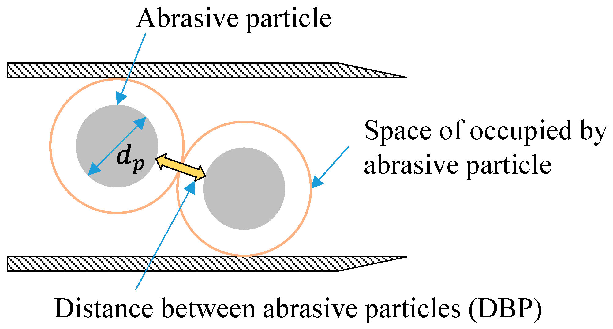
Figure 1. Conceptual illustration of the distance between particles (DBP) in the focus.
Applsci 11 01543 g001
Figure 2. DBP according to AFR, WFR, and focus diameter.
Applsci 11 01543 g002
Figure 3. Orifices and focuses.
Applsci 11 01543 g003
Figure 4. Experimental setup for abrasive waterjet rock cutting with pump and abrasive waterjet system.
Applsci 11 01543 g004
Figure 5. Abrasives for the experiment: (a) India garnet; (b) particle size distribution.
Applsci 11 01543 g005
Figure 6. Schematic drawing of abrasive waterjet rock cutting.
Applsci 11 01543 g006
Figure 7. Cutting results with different focus diameters and WFRs on the granite specimens.
Applsci 11 01543 g007
Figure 8. Rock cutting depth as a function of focus diameter at WFRs of (a) 10.67, (b) 29.5, and (c) 50.00 mL/s.
Applsci 11 01543 g008
Figure 9. DBP as functions of the (a) focus diameter and (b) WFR.
Applsci 11 01543 g009
Figure 10. Abrasive waterjet kinetic energy per second as functions of the AFR and the WFR.
Applsci 11 01543 g010
Figure 11. Energy required to cut a unit depth versus DBP.
Applsci 11 01543 g011
Figure 12. Effect of the focus diameter on the cutting depth owing to WFR.
Applsci 11 01543 g012
Figure 13. Effects of the focus diameter on the cutting depth owing to the AFR.
Applsci 11 01543 g013
Table 1. Previous studies of the effects of the mixing variables on an abrasive waterjet.
VariablesFindingsReference
Focus geometryThe focus geometry affects the momentum transfer efficiency.[16]
Focus geometry–abrasive flow rate (AFR)The optimal mixing efficiency is determined in the space in which mixing occurs.[7]
Focus geometry–AFRThe optimum AFR is a function of pressure, and the focus diameter affects the power density.[22]
Flow rate–focus geometryThe economically optimum focus diameter is three times the orifice diameter.[28]
Focus–orifice geometryThe focus diameter affects the surface roughness and determines 98% of the cutting width.[25]
Focus geometryThe surface profile amplitude and surface roughness mainly depend on the focus diameter.[11]
Focus geometryThe focus diameter is the dominant parameter affecting the cutting width and the surface roughness.[18]
Focus geometry–AFR A larger ratio between the diameters of the focus and abrasive particles reduces the acceleration energy.[27]
Focus and orifice geometry–AFRThe AFR affects the mixing efficiency more strongly than the focus and the water flow rate (WFR).[5]
Table 2. Abrasive waterjet operation conditions and experimental cases.
Orifice Diameter (mm)0.150.2540.33
WFR (mL/s)10.6729.5050.00
Focus diameter (mm)0.761.020.760.911.020.760.911.02
AFR (g/s)3.33.34.04.54.04.44.55.2
4.44.57.17.55.07.410.210.5
5.611.012.08.612.513.315.3
6.613.015.514.020.01.318.8
7.920.018.024.024.024.423.2
10.0 29.0 25.0
Pump pressure (MPa)320
Table 3. Abrasive properties.
Abrasive TypeSourceSpecific GravityMean Particle Size (mm)
Pyrope garnet Mg3Al2(SiO4)3India3.790.18 (Mesh size 80)
Table 4. Granite specimen properties.
UCS
(MPa)
Shear Strength
(MPa)
Tensile Strength
(MPa)
Specific GravityAbsorption Ratio
(%)
Shore Hardness
23623122.650.27114
Publisher’s Note: MDPI stays neutral with regard to jurisdictional claims in published maps and institutional affiliations.