Article

Comparison of Extragraft Bone Formation after Anterior Cervical Discectomy and Fusion Using Simultaneous and Sequential Algorithms

1
Department of Neurosurgery, Inje University College of Medicine, Seoul Paik Hospital, Seoul 04551, Korea
2
Elsoltec Inc., Yongin 17095, Korea
*
Author to whom correspondence should be addressed.
Appl. Sci. 2021, 11(4), 1487; https://doi.org/10.3390/app11041487
Submission received: 19 January 2021 / Revised: 1 February 2021 / Accepted: 3 February 2021 / Published: 6 February 2021

Abstract

:
Extragraft bone formation is crucial for obtaining a successful outcome after spinal fusion surgery. However, the cause of bone formation is not well investigated. In this study, it was hypothesised that extragraft bone formation is generated by mechanical stimuli. A preoperative plan for anterior cervical discectomy and fusion was applied to the finite element model of the C5–C6 motion segment. Extragraft bone formations posterior to the interbody cage were simulated using simultaneous and sequential algorithms. While the simultaneous algorithm predicted the formation of extragraft bone bridging under flexion and extension, the bridge was generated only under extension with the sequential algorithm. This was caused by an ill-defined design space in cases where the simultaneous algorithm was used. Our results using the sequential algorithm show how the progress of extragraft bone formation affects spine mechanics, and our results support the hypothesis that a mechanical stimulus is a major factor influencing extragraft bone formation.

1. Introduction

Bone modelling and remodelling are very important throughout the lifetime of a human being because both processes are related to the bone growth and healing processes. Dr. Julius Wolff purported Wolff’s law, which states that the bone remodels itself to adapt to loads applied to the bone [1]. Because this is similar to the concept of topology optimisation in mechanical engineering, computer simulation studies dealing with the internal architecture of the long bone have been performed to understand the mechanism of the generation of trabecular bone architecture [2,3,4,5]. However, abnormal bone formation not only in the trabecular bone region of the long bones but also on the outer surface of the bone is also critical because it is related to the mechanism of the development of orthopaedic disease and treatments.
In spinal fusion surgery, the most popular surgical method for both the cervical and lumbar spine involves the placement of a spacer, which occupies the intervertebral disc space embedded between the upper and lower vertebral bodies of the operated motion segment. Although autologous bone grafting has been used in spinal fusion when the surgery is introduced, recently, the use of interbody cages filled with bone graft material has become more common, to avoid complications following autologous bone grafting [6,7]. Even in multi-level fusion surgeries, cervical spinal fusion surgeries with a cage (expandable cage) showed similar results to surgeries with iliac crest autografts [8]. Because the purpose of spinal fusion surgery is to integrate two vertebral bodies of the operated motion segment into one solid structure, bone bridging through the prefilled bone graft (intragraft bone bridging) or around the interbody cage (extragraft bone bridging) is necessary to achieve a solid union of the vertebral bodies. A previously published clinical study showed that extragraft bone bridging is critical for achieving a solid union after anterior cervical fusion [6]. Therefore, investigation of bone modelling or remodelling after spinal fusion is crucial for securing a successful outcome from the surgery.
Bone formation around a surgical implant after spinal surgery is observed not only after spinal fusion but also after other surgeries including motion-preserving spine surgeries using an artificial disc, as well as dynamic stabilisation [9,10,11,12]. The concept of an artificial disc involves a ball–socket joint that is used to occupy the disc height while preserving spinal motions along the flexion-extension, lateral, and axial directions. Dynamic stabilisation involves a relatively flexible device, and its low stiffness is helpful for allowing segmental motions. However, many clinical studies have reported that spinal motion is not well preserved after motion-preserving spine surgeries. This is due to abnormally generated bone, which is called heterotopic ossification, that surrounds the embedded artificial disc, interrupting spinal motion as well as inducing the union of the superior and inferior vertebrae.
While bone formation is essential for achieving successful spinal fusion surgery, it is a disadvantage and complication in motion-preserving spine surgeries [6,9,10,11,12]. Therefore, the accurate prediction of bone formation after spinal surgery is important for building preoperative plans and developing spinal surgical devices. Several biomechanical studies have been published in which spinal implants for treating spinal disorders or diseases were assessed using both experimental and computational methods [13,14]. However, although bone formation surrounding the embedded implants is critical in the biomechanical assessment of the implant, only a few studies have investigated bone formation [10,15,16] and its biomechanical effects on the spinal motion segment.
Extragraft bone formation after spinal surgery or heterotopic ossification after motion-preserving spinal surgery is initially generated on the surface of the superior and inferior vertebral bodies, and then grows toward the direction of the opposite side bones. Therefore, an algorithm that can simulate the sequential growth of the bone based on clinical observation is necessary for simulating extragraft bone formation. However, no previously published study has simulated progressive bone formation after spinal surgery. In this study, we developed an algorithm simulating the growth of extragraft bone formation, named the sequential algorithm. The algorithm is based on a hypothesis that mechanical stimuli do play a major role in extragraft bone formation. Extragraft bone formation after anterior cervical discectomy and fusion (ACDF) was simulated using the developed algorithm. The results were compared to those predicted using the conventional bone remodelling algorithm, called the simultaneous algorithm, in which the regions of extragraft bone formation were predefined and extragraft bone formation was predicted simultaneously.

2. Materials and Methods

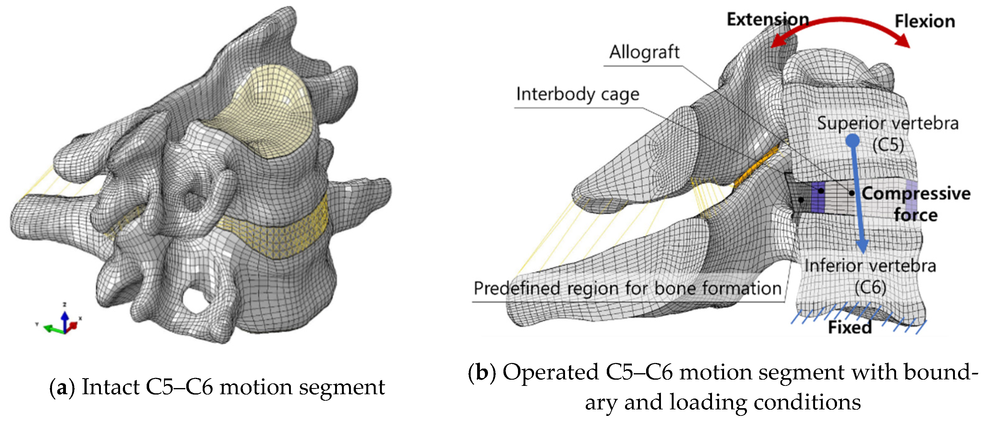
2.1. Finite Element Model of the Operated C5–C6 Motion Segment

The C5–C6 spinal motion segment is the site that bears loads from the neck and head above and provides flexibility to the neck. Thus, degenerative and traumatic diseases are observed most frequently in the motion segment [17,18], and it was chosen to simulate extragraft bone formation in this study. A validated finite element (FE) model of the osteoligamentous C5–C6 motion segment was used (Figure 1) [19], which was developed using anonymised computed tomographic images collected from the Catholic Digital Human Library (Approval No. CUMC10U161, IRB, College of Medicine, The Catholic University of Korea). The model consisted of two vertebral bones, six major ligaments (the anterior and posterior longitudinal ligaments, interspinal and supraspinal ligaments, ligamentum flavum, and capsular ligament), inferior and superior endplates, an intervertebral disc (including the annulus fibrosus and nucleus pulposus), and bilateral facet joints. In total, 79,506 nodes and 75,634 elements were used in developing the FE model of the intact C5–C6 motion segment.
ACDF was applied to the model using a standalone cage. The anterior and posterior longitudinal ligament, nucleus pulposus, and partial annulus fibrosus were removed to simulate discectomy. A three-dimensional FE model of a standalone cage was developed based on the geometry of a cervical cage (Solis cervical cage; Stryker, Allendale, NJ, USA), but the teeth on both the upper and lower planes were neglected. The material properties of polyetheretherketone were applied to the FE model of the cage. Thus, an elastic modulus of 4000 MPa and a Poisson’s ratio of 0.25 were used. For simulating the allograft, the region inside the cage was filled with trabecular bone material (E = 100 MPa and ν = 0.28). The allograft-prefilled standalone cage was embedded into the disc space with the alignment of the anterior end of the cage to the anterior margin of the vertebrae. A three-dimensional surface-to-surface contact condition was established between the superior plane of the cage and inferior plane of the C5 vertebra and between the inferior plane of the cage and the superior plane of the C6 vertebra. A standalone cage was fixed on the vertebral bodies using screws or keels. For simplification, screws or keels were neglected where possible; however, the “no-separation” option was applied to the contact condition for fixing the interbody cage on the vertebrae. Moreover, a high friction coefficient of 0.8 was applied on the contact surface to compensate for the neglected teeth on the superior and inferior planes of the interbody cage.

2.2. Modelling of the Predefined Region for Bone Formation around the Interbody Cage

There was not enough space for bone formation in the anterior region because the interbody cage was aligned at the anterior margin of the vertebrae. Moreover, clinical images showed that bone formation was primarily observed in the region posterior to the interbody cage (Figure 2). Thus, only bone formation in the posterior regions was studied, and the potential bone formation region was predefined in the region posterior to the interbody cage.
The Young’s modulus was calculated using the following equation (Equation (1)) introduced in previously published studies [20,21]:
E = 3790 · ρ 3 ,
where E and ρ are the Young’s modulus and density, respectively. The Young’s modulus of the cortical, the densest, bone is known to be 12,000 MPa, and the corresponding density of the cortical bone is 1.47 g/cm3. The Young’s modulus of the predefined region of bone formation was assumed to be 0.73 g/cm3, which is half that of the cortical bone. Thus, the initial value of the Young’s modulus of the element in the potential region of bone formation was set as 1474 MPa. The elements in the predefined bone formation region were modelled as attached to the upper and lower vertebrae. A three-dimensional surface-to-surface contact condition was defined between the elements of the predefined bone formation region and elements of the interbody cage. A high friction coefficient of 0.8 was used for the contact condition.

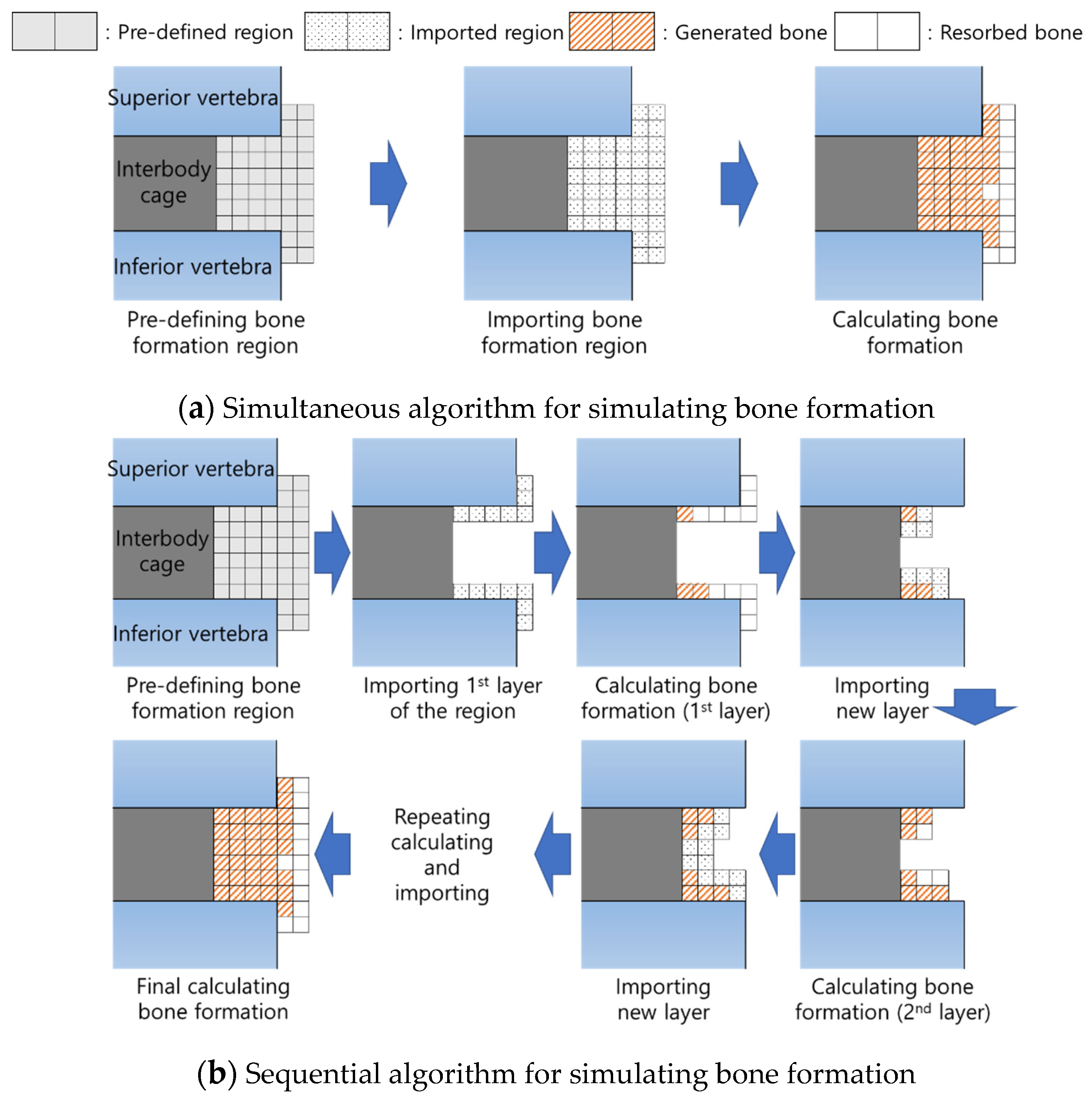
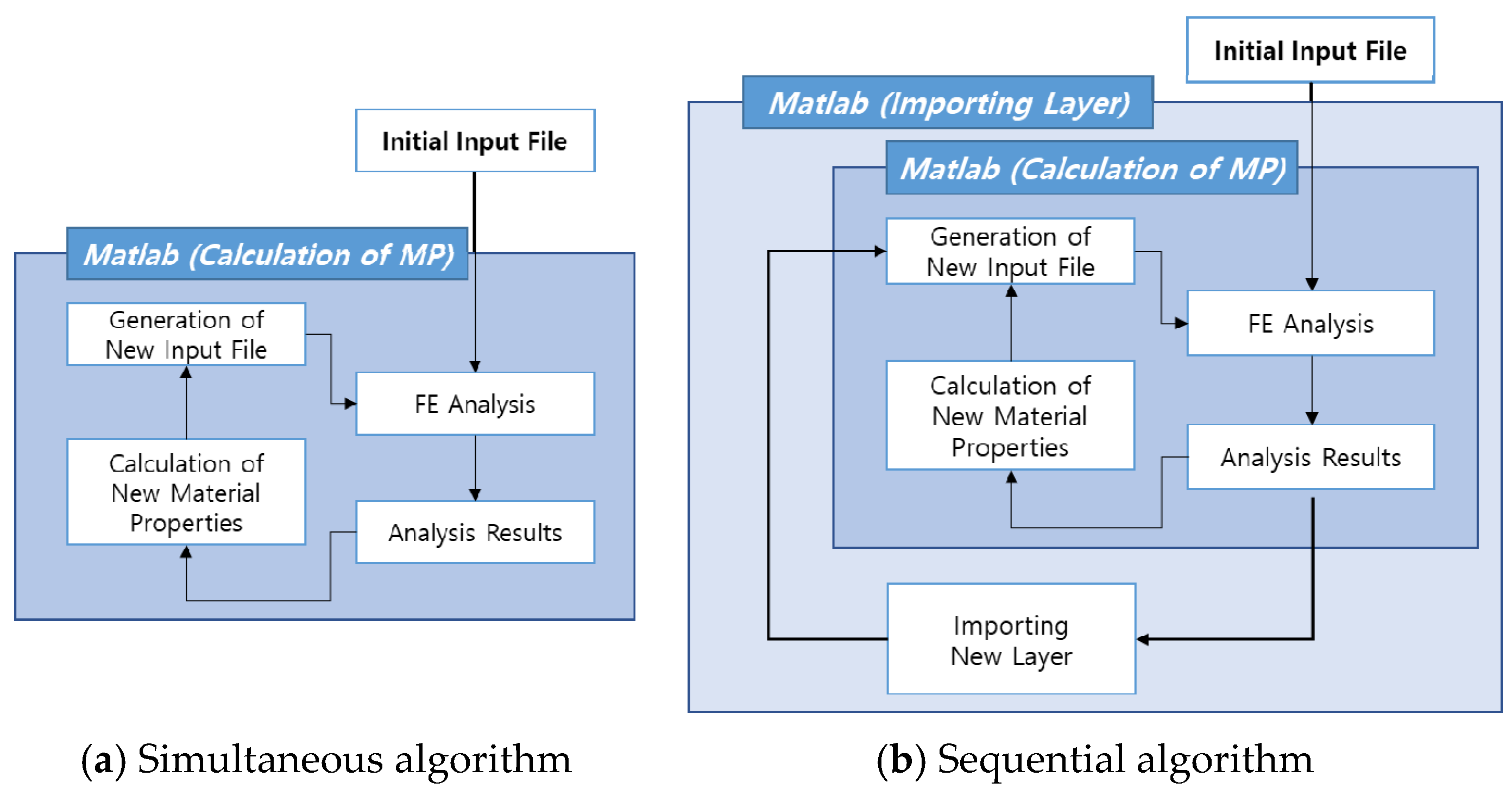
2.3. Simulation of Bone Formation around the Embedded Interbody Cage
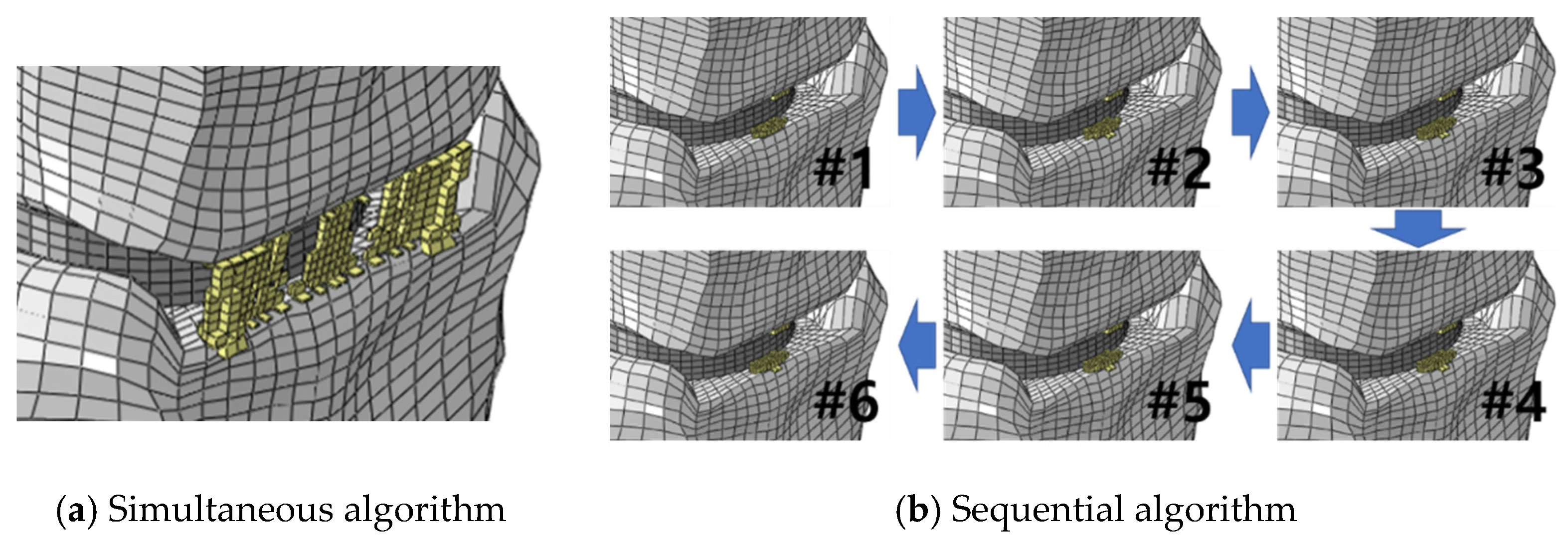
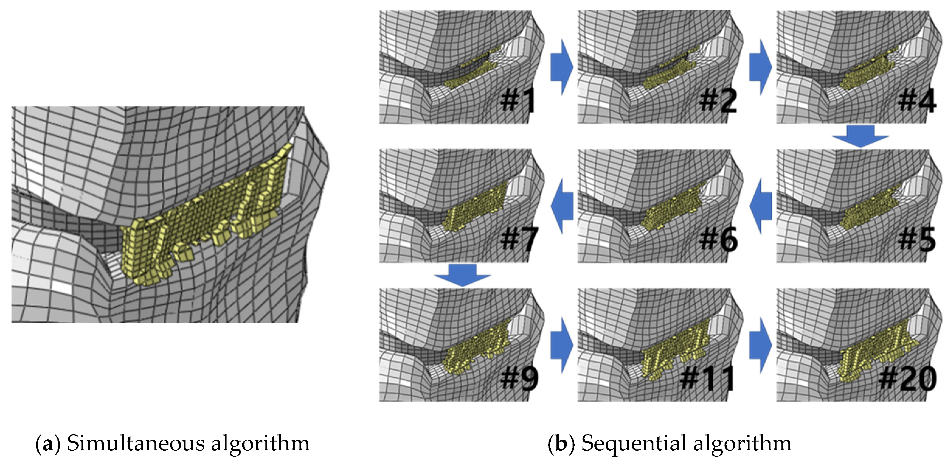
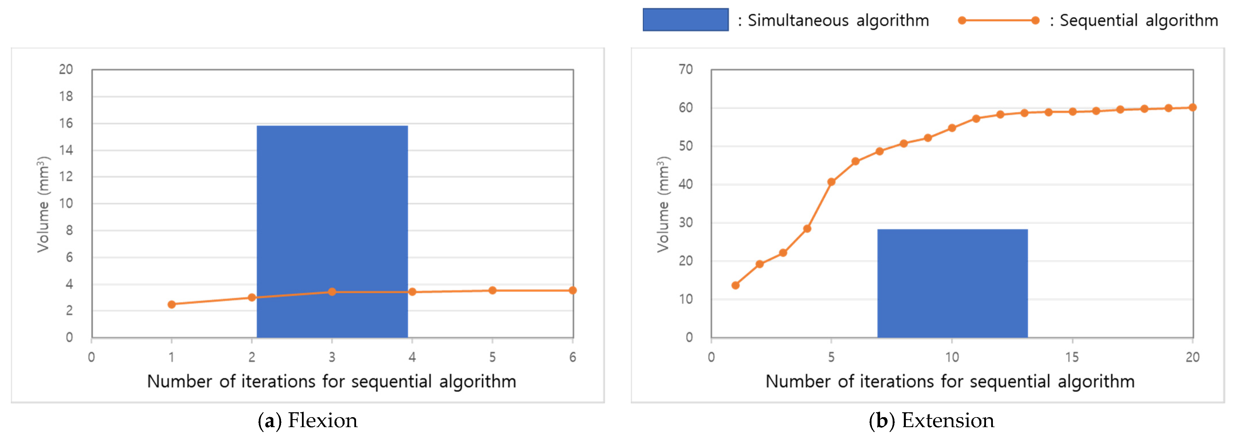
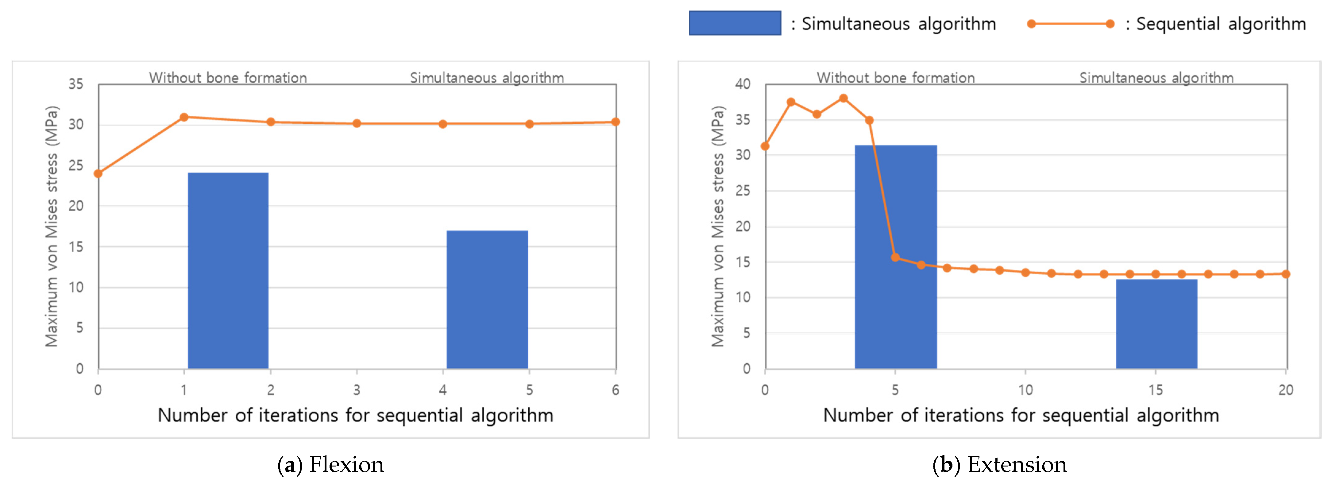
We assumed that the bone formation around the embedded interbody cage was generated via intramembranous ossification. Intramembranous ossification is an osteogenic pathway and involves osteoclasts, which are cells that break down and resorb bone tissue, and osteoblasts, which are cells involved in bone formation. In many previously published studies in which the bone modelling of the trabecular structure was simulated, bone formation and resorption were calculated in all the elements of the predefined region [15,16,20,22,23]. In the simultaneous algorithm, bone formation and resorption are calculated simultaneously (Figure 3a). Then, the elements of the formed bone are preserved and the elements of the resorbed bone are removed after the calculation. Thus, an iteration to calculate the density of the elements in the potential region of bone formation and to simulate bone formation and absorption is imposed (Figure 4a).
Design space topology optimisation, which describes intermediate structural adaptation progress in the time domain, has been developed and utilised to simulate the complex internal bone architecture of the trabecular bone in the human proximal femur [3,4,24]. We adopted the characteristics of design space topology optimisation and developed a sequential bone remodelling algorithm to simulate intramembranous ossification in which layer-by-layer bone formation occurs. In the predefined bone region, the elements adjacent to the superior and inferior vertebrae were imported, and the bone formation and resorption were then calculated as the very first step. After calculation, the elements for the resorbed bone were erased. Then, the elements adjacent to the remaining elements, which were the elements of the formed bone in the previous calculation, were imported, and the bone formation and resorption were calculated again. This process was repeated until new bone formation was no longer generated (Figure 3b). Therefore, in the algorithm, two different iterations were used. One was used to calculate bone formation and absorption, called the internal iteration, and the other was used to import layers adjacent to the vertebrae and generated bone, called the external iteration (Figure 4b).
In both the simultaneous and sequential algorithms, the bone formation and resorption were calculated based on the mechanical stimulation of the strain energy density (SED, U) predicted in the FE analysis. The density of the bone, ρ , of the individual elements imported in both the sequential and simultaneous algorithms was calculated using an equation introduced in previously published studies (Equation (2)) [15,16,20,23] as follows:
d ρ d t = { B ( S ( 1 + s ) K )       i f S > ( 1 + s ) K 0       i f ( 1 s ) K S ( 1 + s ) K B ( S ( 1 s ) K )       i f S < ( 1 s ) K ,
where dt, B, K, and s are the units of time, remodelling rate coefficient, homeostatic equilibrium SED, and threshold range of the lazy zone, respectively. The values for the parameters were set at 30, 1.0 (g/cm3)2, 0.0131 J/g, and 0.2443, respectively [25]. The SED per unit mass, S, was calculated as S = U / ρ . The Young’s modulus of the individual elements was calculated using Equation (1), and a Young’s modulus of the cortical bone of 12,000 MPa was used for the upper boundary. We used 0.1 MPa for the lower boundary, considering the convergence of the FE analysis.
Flexion and extension motions were simulated, and the SED, which is the mechanical stimulation used for calculating bone formation and resorption, was predicted using FE analysis. The inferior plane of the C6 vertebra was fixed in all directions, and 1.5 Nm of flexion and extension moments with 50 N of a compressive force from the centre of the superior vertebra to the centre of the inferior vertebra were applied on the superior plane of the L4 vertebra to simulate flexion and extension motions (Figure 1b). Abaqus/Standard 6.14 (Simulia, Providence, RI, USA) and Matlab 2018a (MathWorks, Inc., Natick, MA, USA) were used for the FE analysis and for developing codes to calculate bone remodelling (bone formation and resorption) with the sequential and simultaneous algorithms. All the analyses were executed on quadcore 2.10 GHz Intel® Xeon processors (Intel Corporation, Santa Clara, CA, USA), and Red Hat Enterprise Linux (Red Hat, Raleigh, NC, USA) was used as the OS.

3. Results

About 18 min was required for simulating each flexion and extension. When the simultaneous algorithm was used, an external iteration for importing the elements surrounding the formed elements was not imposed, but an internal iteration for calculating the new material properties in the predefined region was imposed. A total of 124 calculations were conducted for flexion, and 240 calculations were conducted for extension loading conditions. When the sequential algorithm was used, 6 and 20 external iterations were imposed for the flexion and extension loading conditions, respectively. Moreover, about 24 and 64 calculations were conducted for flexion and extension, respectively, in the internal iteration. Thus, the calculation times were 1.6 and 3 days for flexion and extension, respectively, when the simultaneous algorithm was used. The times were 1.8 and 15.9 days for flexion and extension, respectively, when the sequential algorithm was used.
When the simultaneous algorithm was used, extragraft bone bridging and extragraft bone formation connecting the superior and inferior vertebral bodies were generated in both the flexion and extension loading conditions. However, extragraft bone bridging was generated in only the extension loading condition when the sequential algorithm was used (Figure 5 and Figure 6). The volume of bone formation was 15.82 mm3 in flexion and 28.36 mm3 in extension, when the simultaneous algorithm was used. The volumes of the initial bone formation were 2.55 and 13.9 mm3 in flexion and extension, respectively, when the sequential algorithm was used. They increased to 3.57 and 60.4 mm3 in flexion and extension, respectively (Figure 7).
When extragraft bone formation was not generated, the maximum von Mises stresses on the interbody cage were 24.2 and 31.4 MPa under flexion and extension, respectively (Figure 8). The generation of extragraft bone bridging using the simultaneous algorithm led to decreases in the maximum stresses to 17.0 and 12.6 MPa under flexion and extension, respectively. When the sequential algorithm was used, initial extragraft bone formation increased the maximum stress to 31.1 and 37.7 MPa under flexion and extension, respectively. The stress decreased with the generation of extragraft bone bridging in extension, while the stress decreased slightly with the progress of the iterations in flexion. The maximum stresses at the final steps were 30.5 and 13.5 MPa under flexion and extension, respectively.
The predicted maximum von Mises stresses on the trabecular bone were 3.0 and 4.7 MPa in flexion and extension, respectively, when extragraft bone formation was not generated (Figure 9). The stress in flexion decreased to 0.6 MPa after extragraft bone formation using the simultaneous algorithm, while it decreased to 2.3 MPa after bone formation using the sequential algorithm. The stress in extension decreased to 0.7 MPa after extragraft bone formation using the simultaneous algorithm. During extragraft bone formation using the sequential algorithm, the stepwise decrease in the stress was predicted. The predicted stress was 3.0, 2.0, 1.2, 0.8, 0.7, and 0.8 MPa at the 1st, 2nd, 5th, 10th, 11th, and 20th iterations, respectively.

4. Discussion

Bone formation after spinal fusion is critical for a successful surgical outcome [6,26]. There are two pathways in bone formation, endochondral and intramembranous ossification. However, it is not clear which one is the major mechanism of extragraft bone formation. If endochondral ossification is a major pathway of bone formation during the fracture healing process, intragraft bone formation should be observed more frequently than extragraft bone formation or bridging because the region of intragraft bone formation is filled with graft bone. However, Song et al. reported that extragraft bone bridging had 100% sensitivity and a negative predictive value for diagnosing solid fusion; thus, extragraft bone bridging plays a greater role in securing stability with the formation of a solid union compared with intragraft bone bridging [6]. Moreover, Espinha et al. showed that the force applied to the superior vertebra was mainly transmitted not via the graft bone inside the cage but via the implanted cage itself [22]. Therefore, it is not expected that graft bone inside the cage sustains mechanical loading. However, the bone surrounding the implanted cage could be stimulated by the external load, such as during the bending moment, and the load could lead to extragraft bone formation. Thus, the authors believe that the hypothesis that the mechanism behind the generation of extragraft bone formation and bridging is intramembranous ossification, and that mechanical stimuli mainly affect extragraft bone formation after spinal implantation, is supported. That is why only extragraft bone formation was predicted in this study.
Changes in the trabecular bone structure or density based on Wolff’s law occur according to the magnitudes of the stress and strain and their directions [1,5]. When the simultaneous algorithm was used, stress bearings through the potential bone generation region were predicted in both flexion and extension (Figure 10a,c), and they resulted in the generation of extragraft bone bridging (Figure 6). However, flexion loading only contributed to initial extragraft bone formation, not to growth, when the sequential algorithm was used. Thus, discontinuous stress bearing was shown in flexion (Figure 10b) with the sequential algorithm, and it predicted less volume of generated bone compared to the volume predicted using the simultaneous algorithm. Therefore, the authors believe that a simultaneous algorithm could overestimate extragraft bone formation because of an ill-defined design space. Even though the simultaneous algorithm has the advantage of reducing the calculation time (Table 1), the computing time can be reduced with a decrease in the number of elements of the FE model or an increase in the number of analysis processors.
To our knowledge, the first study to simulate bone formation after spinal surgery using an implanted device was conducted by Ganbat et al. [15,16]. That study conducted the simulation of heterotopic ossification formation after cervical disc arthroplasty using a simultaneous algorithm. Even though the simulation results in the previously published studies were consistent with clinical observations, there may have been overestimated bone formation caused by a load sharing pathway in the simultaneous algorithm, as shown in the results of this study. Therefore, the authors believe that the sequential algorithm introduced in this study could help the accurate prediction of bone formation, even for heterotopic ossification.
The causes of pathologic bone formation are controversial, and various factors including sex, age, and surgical method have been presumed as causes of pathologic bone formation [12,27,28]. The authors believe that the major advantage of the sequential bone formation algorithm, compared to the simultaneous one, is showing intermediate bone formation progress, and this provides critical information for understanding the mechanism of bone formation. The extragraft bone (Figure 6) was generated along the directions of principal stress shown in Figure 10. Thus, when the sequential algorithm was used, the extragraft bone was initially generated on the surfaces of the vertebrae, it grew up to the wedge shape, and then, finally, extragraft bone bridging was formed. This progress showed good agreement with the clinical observation shown in Figure 2. These results support the hypothesis in this study.
With the stepwise decreases in the maximum von Mises stresses on both the interbody cage and trabecular bone in extension with the sequential algorithm, slight changes in stresses were predicted in flexion (Figure 8 and Figure 9). However, the simultaneous algorithm did not show changes in the mechanical behaviours of the spine during the progress of extragraft bone formation. At the fifth iteration in the extension loading condition with the sequential algorithm, extragraft bone bridging in the trabecular bone region was predicted, and the bridge extended to the cortical region at the 10th iteration. Although the stress on the interbody cage increased with the initial generation of extragraft bone formation, a sudden decrease in the maximum stress on the interbody cage was predicted with extragraft bone bridge formation (at the fifth iteration) (Figure 8b). The maximum stress on the trabecular bone in the vertebra decreased even with the initial extragraft bone formation (Figure 9b). The second step of the decrease in the maximum stress in the trabecular bone was shown with extragraft bone bridge formation (at the fifth step), and the third step of the decrease was shown with the expansion of bone bridging to the cortical bone region (at the 10th step). Even though the inserted interbody cage affects bone adaptation in the trabecular bone of the vertebrae [22], extragraft bone formation should also be considered for the accurate prediction of bone adaptation in the vertebrae.
There were several limitations to this study. For the bone modelling and remodelling simulation to predict the trabecular bone architecture, a large-scale FE model with millions of micrometre-level elements was used (50 µm [29], 87.5 µm [5], and 175 µm [4]). However, in this study, the maximum number of elements used for simulating extragraft bone formation was 2576, and the mean volume of the elements used for simulating extragraft bone formation was approximately 0.0755 mm3. Given that not only extragraft bone formation but also the motion segmental unit should be simulated together, the authors used a very limited number of elements for simulating extragraft bone formation. A recent computer simulation study predicted bone adaptation with consideration of resorption in the presence of an excessive mechanical stimulus [30]. When a cage is inserted in the intradiscal space, bone subsidence at the interface between the vertebrae and the inserted cage might occur because of excessive mechanical stimuli, including stress, strain, or the SED. These factors could affect the formation of both intra- and extragraft bone because of a decrease in the disc height and changes in the mechanical stimuli on the vertebrae. The bone remodelling algorithms used in this study were developed based on a trilinear bone adaptive algorithm introduced in previously published studies [20,21], and bone resorption caused by an excessive mechanical stimulus was neglected. Despite these limitations, the extragraft bone formation predicted using the sequential algorithms showed good agreement with clinical observations. In this study, normal spinal bones of the C5–C6 segment were considered. However, abnormalities of the spinal bones have been reported in previously published clinical studies [31,32,33,34], especially the anomaly that most commonly affects the C6 level [31]. The congenital absence of a cervical spine pedicle is a rare condition, and the absence of the pedicle is usually found after trauma in patients with cervical pain [34]. A spinal bony abnormality results in changes in loading and in its path in the spinal motion segment; thus, extragraft bone formation in patients who have bony abnormalities may differ from the results of this study.

5. Conclusions

In this study, extragraft bone formation after ACDF was simulated using two different bone remodelling algorithms, simultaneous and sequential. Even though the simultaneous algorithm has been used to simulate the trabecular bone structure of the femoral head, the results of this study show that it could overestimate extragraft bone formation as a result of an ill-defined design space. Therefore, the sequential algorithm should be used for simulating extragraft bone formation as well as heterotopic ossification. Moreover, the results of this study, including the extragraft bone formation simulated using the sequential algorithm, support the hypothesis that a mechanical stimulus influences the extragraft bone formation.

Author Contributions

Conceptualization, Y.J.J.; methodology, Y.J.J. and W.M.P.; formal analysis, Y.J.J. and W.M.P.; investigation, Y.J.J. and W.M.P.; writing—original draft preparation, Y.J.J. and W.M.P.; visualization, W.M.P. All authors have read and agreed to the published version of the manuscript.

Funding

This research was supported by the Basic Science Research Program through the National Research Foundation of Korea (NRF) funded by the Ministry of Education (No. NRF-2017R1D1A1B03034668).

Institutional Review Board Statement

Not applicable.

Informed Consent Statement

Not applicable.

Data Availability Statement

Not applicable.

Conflicts of Interest

The authors declare no conflict of interest. The funders had no role in the design of the study; in the collection, analyses, or interpretation of data; in the writing of the manuscript; or in the decision to publish the results.

References

  1. Wolff, J. Das Gesetz von der Transformation der Knochen; Pro Business: Berlin, Germany, 1892; ISBN 9783868056488. [Google Scholar]
  2. Jang, I.G.; Kim, I.Y. Application of design space optimization to bone remodeling simulation of trabecular architecture in human proximal femur for higher computational efficiency. Finite Elem. Anal. Des. 2010, 46, 311–319. [Google Scholar] [CrossRef]
  3. Jang, I.G.; Kim, I.Y.; Kwak, B.B. Analogy of strain energy density based bone-remodeling algorithm and structural topology optimization. J. Biomech. Eng. 2009, 131, 011012. [Google Scholar] [CrossRef]
  4. Boyle, C.; Kim, I.Y. Three-dimensional micro-level computational study of Wolff’s law via trabecular bone remodeling in the human proximal femur using design space topology optimization. J. Biomech. 2011, 44, 935–942. [Google Scholar] [CrossRef]
  5. Tsubota, K.I.; Suzuki, Y.; Yamada, T.; Hojo, M.; Makinouchi, A.; Adachi, T. Computer simulation of trabecular remodeling in human proximal femur using large-scale voxel FE models: Approach to understanding Wolff’s law. J. Biomech. 2009, 42, 1088–1094. [Google Scholar] [CrossRef]
  6. Song, K.S.; Chaiwat, P.; Kim, H.J.; Mesfin, A.; Park, S.M.; Riew, K.D. Anterior cervical fusion assessment using reconstructed computed tomographic scans: Surgical confirmation of 254 segments. Spine 2013, 38, 2171–2177. [Google Scholar] [CrossRef]
  7. Lee, S.E.; Chung, C.K.; Kim, C.H. Difference in canal encroachment by the fusion mass between anterior cervical discectomy and fusion with bone autograft and anterior plating, and stand-alone cage. J. Clin. Neurosci. 2016, 29, 121–127. [Google Scholar] [CrossRef]
  8. Perrini, P.; Gambacciani, C.; Martini, C.; Montemurro, N.; Lepori, P. Anterior cervical corpectomy for cervical spondylotic myelopathy: Reconstruction with expandable cylindrical cage versus iliac crest autograft. A retrospective study. Clin. Neurol. Neurosurg. 2015, 139, 258–263. [Google Scholar] [CrossRef]
  9. Maida, G.; Marcati, E.; Sarubbo, S. Heterotopic Ossification in Vertebral Interlaminar/Interspinous Instrumentation: Report of a Case. Case Rep. Surg. 2012, 2012, 970642. [Google Scholar] [CrossRef] [Green Version]
  10. Jin, Y.J.; Park, S.B.; Kim, M.J.; Kim, K.J.; Kim, H.J. An analysis of heterotopic ossification in cervical disc arthroplasty: A novel morphologic classification of an ossified mass. Spine J. 2013, 13, 408–420. [Google Scholar] [CrossRef]
  11. Lee, J.-H.; Jung, T.-G.; Kim, H.-S.; Jang, J.-S.; Lee, S.-H. Analysis of the incidence and clinical effect of the heterotopic ossification in a single-level cervical artificial disc replacement. Spine J. 2010, 10, 676–682. [Google Scholar] [CrossRef]
  12. Yi, S.; Kim, K.N.; Yang, M.S.; Yang, J.W.; Kim, H.; Ha, Y.; Yoon, D.H.; Shin, H.C. Difference in occurrence of heterotopic ossification according to prosthesis type in the cervical artificial disc replacement. Spine 2010, 35, 1556–1561. [Google Scholar] [CrossRef]
  13. Montemurro, N.; Perrini, P.; Mangini, V.; Galli, M.; Papini, A. The Y-shaped trabecular bone structure in the odontoid process of the axis: A CT scan study in 54 healthy subjects and biomechanical considerations. J. Neurosurg. Spine 2019, 1, 1–8. [Google Scholar] [CrossRef]
  14. Teo, E.C.; Ng, H.W. First cervical vertebra (atlas) fracture mechanism studies using finite element method. J. Biomech. 2001, 34, 13–21. [Google Scholar] [CrossRef]
  15. Ganbat, D.; Kim, K.; Jin, Y.J.; Kim, Y.H. Heterotopic ossification in cervical total disk replacement: A finite element analysis. Proc. Inst. Mech. Eng. Part H J. Eng. Med. 2014, 228, 200–205. [Google Scholar] [CrossRef]
  16. Ganbat, D.; Kim, Y.H.; Kim, K.; Jin, Y.J.; Park, W.M. Effect of mechanical loading on heterotopic ossification in cervical total disc replacement: A three-dimensional finite element analysis. Biomech. Model. Mechanobiol. 2016, 15, 1191–1199. [Google Scholar] [CrossRef]
  17. Malcolm, G.P. Surgical disorders of the cervical spine: Presentation and management of common disorders. Neurol. Pract. 2002, 73, i34–i41. [Google Scholar] [CrossRef]
  18. Quraishi, N.A.; Elsayed, S. A traumatic, high-energy and unstable fracture of the C5 vertebra managed with kyphoplasty: A previously unreported case. Eur. Spine J. 2011, 20, 1589–1592. [Google Scholar] [CrossRef] [Green Version]
  19. Park, W.M.; Jin, Y.J. Biomechanical investigation of extragraft bone formation influences on the operated motion segment after anterior cervical spinal discectomy and fusion. Sci. Rep. 2019. [Google Scholar] [CrossRef]
  20. Weinans, H.; Huiskes, R.; Grootenboer, H.J. The behavior of adaptive bone-remodeling simulation models. J. Biomech. 1992, 25, 1425–1441. [Google Scholar] [CrossRef] [Green Version]
  21. Carter, D.R.; Hayes, W.C. The Compressive Behavior Porous of Bone Structure as a Two-Phase. J. bone Jt. Surg. 1977, 59, 954–962. [Google Scholar] [CrossRef]
  22. Espinha, L.C.; Fernandes, P.R.; Folgado, J. Computational analysis of bone remodeling during an anterior cervical fusion. J. Biomech. 2010, 43, 2875–2880. [Google Scholar] [CrossRef]
  23. Huiskes, R.; Weinans, H.; Grootenboer, H.J.; Dalstra, M.; Fudala, B.; Slooff, T.J. Adaptive bone-remodeling theory applied to prosthetic-design analysis. J. Biomech. 1987, 20, 1135–1150. [Google Scholar] [CrossRef] [Green Version]
  24. Kim, I.Y.; Kwak, B.M. Design space optimization using a numerical design continuation method. Int. J. Numer. Methods Eng. 2002, 53, 1979–2002. [Google Scholar] [CrossRef]
  25. Schulte, F.A.; Zwahlen, A.; Lambers, F.M.; Kuhn, G.; Ruffoni, D.; Betts, D.; Webster, D.J.; Müller, R. Strain-adaptive in silico modeling of bone adaptation—A computer simulation validated by in vivo micro-computed tomography data. Bone 2013, 52, 485–492. [Google Scholar] [CrossRef] [PubMed]
  26. Park, S.B.; Yang, H.J.; Kim, C.H.; Chung, C.K. Difference in spinal fusion process in osteopenic and nonosteopenic living rat models using serial microcomputed tomography. J. Korean Neurosurg. Soc. 2017, 60, 348–354. [Google Scholar] [CrossRef]
  27. Puzas, J.E.; Miller, M.D.; Rosier, R.N. Pathologic bone formation. Clin. Orthop. Relat. Res. 1989, 245, 269–281. [Google Scholar] [CrossRef]
  28. Leung, C.; Casey, A.T.; Goffin, J.; Kehr, P.; Liebig, K.; Lind, B.; Logroscino, C.; Pointillart, V. Clinical significance of heterotopic ossification in cervical disc replacement: A prospective multicenter clinical trial. Neurosurgery 2005, 57, 759–763. [Google Scholar] [CrossRef]
  29. Jang, I.G.; Kim, I.Y. Computational study of Wolff’s law with trabecular architecture in the human proximal femur using topology optimization. J. Biomech. 2008, 41, 2353–2361. [Google Scholar] [CrossRef]
  30. Mauck, J.; Wieding, J.; Kluess, D.; Bader, R. Numerical simulation of mechanically stimulated bone remodelling. Curr. Dir. Biomed. Eng. 2016, 2, 643–647. [Google Scholar] [CrossRef]
  31. Perrini, P.; Montemurro, N. Congenital absence of a cervical spine pedicle. Neurol. India 2016, 64, 189–190. [Google Scholar] [CrossRef]
  32. Dimitrov, D.F.; Bronec, P.R.; Friedman, A.H. Congenitally absent C-7 pedicle presenting as a jumped locked facet. Case illustration. J. Neurosurg. 2003, 99, 239. [Google Scholar] [CrossRef]
  33. Wiener, M.D.; Martinez, S.; Forsberg, D.A. Congenital absence of a cervical spine pedicle: Clinical and radiologic findings. Am. J. Roentgenol. 1990, 155, 1037–1041. [Google Scholar] [CrossRef] [PubMed]
  34. Oh, Y.M.; Eun, J.P. Congenital absence of a cervical spine pedicle: Report of two cases and review of the literature. J. Korean Neurosurg. Soc. 2008, 44, 389–391. [Google Scholar] [CrossRef] [PubMed]
Figure 1. A validated finite element (FE) model of the C5–C6 motion segment with boundary and loading conditions.
Applsci 11 01487 g001
Figure 2. Medical images of the generated bone posterior to the inserted interbody cage after anterior cervical discectomy and fusion (ACDF) surgery.
Applsci 11 01487 g002
Figure 3. Schematic diagram of bone formation around an embedded interbody cage using two algorithms.
Applsci 11 01487 g003
Figure 4. Flow charts of two algorithms.
Applsci 11 01487 g004
Figure 5. Bone formation during flexion using the two algorithms.
Applsci 11 01487 g005
Figure 6. Bone formation during extension using two algorithms: (a) simultaneous and (b) sequential algorithms.
Applsci 11 01487 g006
Figure 7. Bone formation using simultaneous and sequential algorithms during (a) flexion and (b) extension.
Applsci 11 01487 g007
Figure 8. Changes in the maximum von Mises stress on the interbody cage when simulating bone formation using two algorithms during (a) flexion and (b) extension.
Applsci 11 01487 g008
Figure 9. Changes in the maximum von Mises stress on the trabecular bone when simulating bone formation using two algorithms during (a) flexion and (b) extension.
Applsci 11 01487 g009
Figure 10. Directions of the maximum principal stress in the predefined potential region of the extragraft bone formation region during (a,b) flexion (c,d) and extension.
Applsci 11 01487 g010
Table 1. Computing time for simulating bone formation after ACDF using the simultaneous and sequential algorithms.
Loading ConditionNumber of IterationsComputing Time (Days)
InnerOuter
Simultaneous algorithmFlexion12411.6
Extension24013.0
Sequential algorithmFlexion2461.8
Extension642015.9
Publisher’s Note: MDPI stays neutral with regard to jurisdictional claims in published maps and institutional affiliations.

