Article

Time Domain Spherical Harmonic Processing with Open Spherical Microphones Recording

by
Huiyuan Sun
*,†,
Thushara D. Abhayapala
and
Prasanga N. Samarasinghe
Audio & Acoustic Signal Processing Group, College of Engineering and Computer Science, Australian National University, Canberra 2601, Australia
*
Author to whom correspondence should be addressed.
These authors contributed equally to this work.
Appl. Sci. 2021, 11(3), 1074; https://doi.org/10.3390/app11031074
Submission received: 24 November 2020 / Revised: 16 January 2021 / Accepted: 21 January 2021 / Published: 25 January 2021
(This article belongs to the Section Acoustics and Vibrations)

Abstract

:

Featured Application

Spatial Active Noise control.

Abstract

Spherical harmonic analysis has been a widely used approach for spatial audio processing in recent years. Among all applications that benefit from spatial processing, spatial Active Noise Control (ANC) remains unique with its requirement for open spherical microphone arrays to record the residual sound field throughout the continuous region. Ideally, a low delay spherical harmonic recording algorithm for open spherical microphone arrays is desired for real-time spatial ANC systems. Currently, frequency domain algorithms for spherical harmonic decomposition of microphone array recordings are applied in a spatial ANC system. However, a Short Time Fourier Transform is required, which introduces undesirable system delay for ANC systems. In this paper, we develop a time domain spherical harmonic decomposition algorithm for the application of spatial audio recording mainly with benefit to ANC with an open spherical microphone array. Microphone signals are processed by a series of pre-designed finite impulse response (FIR) filters to obtain a set of time domain spherical harmonic coefficients. The time domain coefficients contain the continuous spatial information of the residual sound field. We corroborate the time domain algorithm with a numerical simulation of a fourth order system, and show the proposed method to have lower delay than existing approaches.

1. Introduction

Spherical harmonic analysis has been widely used for spatial acoustic signal processing for years [1]. Sound field recordings can be decomposed into a set of orthogonal spatial basis functions and respective coefficients when an appropriately designed spherical microphone array is used [2,3]. The spherical harmonic decomposition has the advantage that a given sound field can be analyzed over a continuous spatial region rather than a set of distributed points [4]. This has embraced a wide range of algorithms in three-dimensional (3D) audio signal processing such as: sound intensity analysis [5], sound field diffusive analysis [6], beamforming [7,8], source localization [9,10], and spatial Active Noise Control (ANC) [11,12].
A spatial ANC system aims to reduce the unwanted acoustic noise [13] over a space in order to create a silent zone for people. Multiple microphones are used to record the residual noise, and multiple loudspeakers are used to generate the anti-noise field. The recording’s accuracy of the residual sound field can highly influence the performance of an ANC system. Furthermore, recording efficiency is also important, as ANC usually focuses on low frequency and time-variant noise. As a result, an accurate and low latency algorithm for residual sound field recording is desired [14].
The sound field recording step in a spatial ANC system focuses on obtaining the location independent spherical harmonic coefficients that represent the residual sound field inside a region of interest. This is different to real time spherical harmonic beamforming or directivity analysis which focuses on extracting source location information from the spatial recording. Moreover, spatial ANC mainly focuses on reducing the sound field inside the spherical microphone array (the region of interest). While other spatial recording applications may focus on analysing the sound field exterior to the array. Additionally, although most of the spatial audio applications utilize a rigid spherical array [15,16,17] for its convenience to build and use, an open spherical array is considered to be more suitable for a spatial ANC system. This is because users should be able to enter and move within the ANC region of interest that is surrounded by the spherical microphone array [12,18]. Furthermore, there exists previous work focusing on optimising the open array for spherical harmonic recording [19,20], and for spatial ANC systems [21]. However, we consider the optimisation of the open microphone array design to be outside of the scope of this paper, and instead focus on a time-domain recording algorithm.
Real-time spatial beamforming systems illustrate that applications with strict delay requirements can highly benefit from the small latency and efficient computation of time domain processing [22,23]. By posing the signal processing algorithm in the time domain, system performance can be optimized with real-valued lower order filters [24], and lower modeling delays [25]. Specifically, for a spatial ANC system, the system delay which includes the filter group delay (signal processing algorithm), the A/D and D/A converter, and the data processing delay, should be less than the acoustic delay from the reference microphones to the secondary loudspeakers in order to satisfy causality [26]. Furthermore, a longer signal processing delay slows down the convergence speed of the adaptive filtering and may lead to an unstable system [27,28]. Therefore, it is worthwhile to consider a time domain spherical harmonic decomposition method to achieve sound field recording with an open spherical array for the application of spatial ANC.
Frequency domain spherical harmonic recording has been well developed with various optimised filters [29,30,31]. One benefit of developing the method in the frequency domain is that the influence of the spherical Bessel zeros can be easily removed by avoiding the estimation of the coefficients at these erroneous frequency bins [19,32,33,34]. However, when we consider a time domain method, we can not simply avoid the Bessel zeros because we do not apply a Fourier Transformation to separate the Bessel zero frequency components from the others.
Meanwhile, there are also several works relate to time domain spatial audio signal processing. In [35], Poletti and Abhayapala give a time domain description of the free-space Green’s function in the spherical harmonic domain. This provides a solution to decompose the free-space channel between a loudspeaker and microphone into the time-space domain. This work only targets the free-space Green’s function, and as a result, the method is highly limited to the application of free space sound field reproduction. In [36], a time domain wave field synthesis method is presented. Although an IFFT is applied to derive the time domain solution, the work still demonstrates that time-domain wave field synthesis can be beneficial to time-varying spatial acoustic applications. In [37], Hahn and Spors offer a time domain representation of the spherical harmonic equation. They relate the time domain spherical harmonic coefficients to the sound pressure, but do not include the method of obtaining the time domain coefficients from a given recording. Time domain beamformers are designed in [38,39] with the IFFT of spherical harmonics. These papers show certain advantages for finite impulse response (FIR) filtering based signal processing systems. Overall, these time domain approaches illustrate the advantages of time domain signal processing, however, they remain unable to obtain location-independent spherical harmonic coefficients. This makes them ill-suited for spatial ANC systems, as these location-independent coefficients provide necessary information about the continuous residual sound field inside the region of interest.
In this paper, we propose a FIR filter based time domain spherical harmonic analysis method to accurately record spatial sound fields with an open spherical microphone array for the purpose of spatial ANC. We note that this work focuses solely on the problem of sound field recording, and that the spatial ANC application acts purely as motivation to our problem. Therefore, with spatial ANC in mind, the recording method prioritizes a minimum processing delay, a bandwidth of interest (low frequencies for typical noise scenarios), and a practical array geometry (open sphere surrounding a quite zone). Employing the recording method in an actual ANC system, and its evaluation, is out of the scope of this paper. The novelty of the presented work is the investigation of time domain spherical harmonic coefficients. These time domain coefficients match the properties of conventional frequency domain spherical harmonic coefficients. That is, the coefficients are location independent within the region of interest, and they represent the continuous sound field over the space. Additionally, these coefficients are obtained in time domain, which relieves the block processing constraint (and can do sample-by-sample processing) and results in lower system delay. Hence, the proposed method is considered to be highly beneficial to spatial ANC systems.
We organise the main body of this paper as follows: In Section 2 we detail the background of the frequency domain spherical harmonic algorithm for spatial sound field recording. Additionally, we introduce the time domain equation of spherical harmonic decomposition, while addressing the challenges of recording time domain spherical harmonic coefficients. The filter’s design and implementation to obtain time domain spherical harmonic coefficients is presented in Section 3, along with error analysis. Effects of truncation and filter length are shown in Section 4 via initial simulations of filter performance. Section 5 presents simulation results for the proposed method’s estimation of spherical harmonic coefficients, as well as sound field reconstruction performance at a point and over space, verifying the effectiveness of the proposed theory and design. We conclude the findings and insights gained from this work in Section 6.

2. Problem Formulation

We begin this section by reviewing the well-known frequency domain spherical harmonic decomposition method. We then introduce the corresponding time domain formulation, and detail the Fourier Transform relationship between the components in the frequency domain equation and the time domain equivalent. Finally, we show the difficulties in obtaining spherical harmonic coefficients in the time domain.

2.1. Spherical Harmonic Decomposition of Sound Field in Frequency-Space Domain

An incident sound field at any arbitrary point x = ( r , θ , ϕ ) inside a source free 3D spherical region Ω , where r refers to the distance between the point x and the origin, θ and ϕ denote elevation and azimuth angles, respectively [40], can be expressed in the frequency domain as [1,41]
S ( x , k ) = n = 0 N m = n n α n m ( k ) j n ( k r ) Y n m ( θ , ϕ ) ,
where order n ( n 0 ) and mode m are integers, N = k R [1], k = 2 π f / c is the wave number, f is frequency, c is the speed of sound, R is the radius of Ω , α n m ( k ) is a set of spherical harmonic coefficients representing the sound field inside Ω , j n ( k r ) is the nth order spherical Bessel function of the first kind, Y n m ( θ , ϕ ) are the spherical harmonic functions. For convenience, we use real spherical harmonics in this paper, given by [42]
Y n m ( θ , ϕ ) = ( 1 ) | m | 2 n + 1 4 π ( n | m | ) ! ( n + | m | ) ! × P n m ( cos θ ) cos ( m ϕ ) m 0 P n m ( cos θ ) sin ( m ϕ ) m < 0 ,
where P n m ( · ) is the associated Legendre function. Real spherical harmonics have the orthogonality property of
0 2 π 0 π Y n m ( θ , ϕ ) Y n m ( θ , ϕ ) sin θ d θ d ϕ = δ n n δ m m .
If the spherical harmonic coefficients α n m ( k ) are available for a sound field, then these coefficients can fully describe the sound field over the continuous spatial region of interest. Traditionally, when spatial harmonic processing is used to record a spatial sound field S ( x , k ) , it is recorded over a spherical surface of radius R Q ( R Q r ) . The corresponding α n m ( k ) are extracted by integrating (1) over the spherical surface while exploiting the orthogonality property of Y n m ( · ) in (3), which gives [2]
α n m ( k ) = 1 j n ( k r ) 0 2 π 0 π S ( r , θ , ϕ , k ) Y n m ( θ , ϕ ) sin θ d θ d ϕ .
In practice, this integration is realized using an equivalent discrete summation of spatial samples over the sphere.

2.2. Equivalent Spherical Harmonic Decomposition of a Sound Field in Time-Space Domain

While the frequency domain spatial sound field capture is well established as explained in Section 2.1, in this paper, our objective is to investigate the possibility of an analogous spherical harmonic analysis in time domain. In a similar fashion to (1) and (4), we now consider the relationship between sound pressure s ( x , t ) recorded by a spherical microphone array and the time domain spherical harmonic coefficients, denoted as a n m ( t ) . It is desirable to have these time domain coefficients a n m ( t ) independent of the measurement radius. Thus, we only need to record a n m ( t ) to obtain the sound field over the entire region of interest Ω . A time domain method can directly extract a n m ( t ) , thus avoiding the Fourier transformation of signals.
As a time domain analysis is usually with real-valued components, we rewrite (1) in the form of
S ( x , k ) = n = 0 N m = n n i n α n m ( k ) j n ( k r ) i n Y n m ( θ , ϕ ) ,
where i = 1 , in order to make the inverse Fourier transform of all terms to be real. Taking the inverse Fourier transformation of (5), we obtain
s ( x , t ) = n = 0 N m = n n a n m ( t ) p n ( t , r ) Y n m ( θ , ϕ ) ,
where * denotes the convolution operation,
a n m ( t ) F i n α n m ( k ) ,
where F denotes the Fourier transform operator,
p n ( t , r ) F j n ( k r ) i n ,
which is given by
p n ( t , r ) = c 2 r P n ( t c r ) r c t r c 0 | t | > r c ,
where P n ( · ) is the Legendre function. The proof of (9) is given in Appendix A. We note that every component in (6) is real valued.
Equation (6) shows how to reconstruct the sound pressure at x = ( r , θ , ϕ ) with the recorded time domain spherical harmonic coefficients a n m ( t ) . We consider an alternative time domain filter to obtain a n m ( t ) from the recorded signals rather than taking the inverse Fourier transform of (4) since 1 / j n ( k r ) is unbounded when j n ( k r ) = 0 . Note that j n ( k r ) as a filter has order dependent zeros when j n ( k r ) = 0 . As a result, 1 / j n ( k r ) approaches infinity at these frequencies, making it unstable to have an inverse Fourier transform. In other words, the z-transform of p n ( t , r ) given in (9), has zeros on the unit circle because of Bessel zeros, refers to a non-minimum phase system. In this case, the inverse system of p n ( t , r ) , with the frequency response of 1 / j n ( k r ) is not stable. As a result, we first define
b n m ( t , r ) a n m ( t ) p n ( t , r ) ,
which has a frequency response of
b n m ( t , r ) F i n α n m ( k ) j n ( k r ) i n = α n m ( k ) j n ( k r ) .
Since Y n m ( θ , ϕ ) is independent to both frequency and time, b n m ( t , r ) can be obtained by integrating (6) over a sphere of radius r such that
b n m ( t , r ) = 0 2 π 0 π S ( r , θ , ϕ , t ) Y n m ( θ , ϕ ) sin ( θ ) d θ d ϕ .
If we regularly place Q ( N + 1 ) 2 omni-directional microphones on a sphere of radius R Q , we can estimate the integration in (12) with a finite summation such that
b n m ( t , R Q ) q = 1 Q S ( x q , t ) Y n m ( θ q , ϕ q ) .
To simplify the implementation, we sample the signals with sampling time T such that t = ν T = ν / F s , where ν is the time index and F s is the sampling frequency. We rewrite (10) as
b n m ( ν , R Q ) = a n m ( ν ) p n ( ν , R Q ) = μ = L p L p p n ( μ , R Q ) a n m ( ν μ ) ,
where
p n ( ν , R Q ) = c 2 R Q P n ( ν c R Q F s ) R Q F s c ν R Q F s c 0 | ν | > R Q F s c ,
is a time limited function with p n ( ν , r ) 0 when L p ν L p , L p = R Q F s / c such that the length of p n ( ν , R Q ) is 2 L p + 1 .
With (14) in hand, our problem reduces to obtaining a n m ( ν ) from the measured b n m ( ν , R Q ) . This is not achievable since it is an under-determined problem. We always have 2 L p + 1 more unknowns ( a n m ( ν ) ) than knowns ( b n m ( ν , R Q ) ). Moreover, this is not practically feasible because the z-transform of p n ( ν , R Q ) has zeros on the unit circle, resulting in poles on the unit circle in its direct inverse, making the system unstable. Alternatively, a n m ( ν ) can be extracted from b n m ( ν , R Q ) using an appropriately designed filter.
In this paper, we attempt to design a filtering solution while overcoming the above challenges. It is important to note that the Fourier transform relationship discussed in this section were solely used to formulate the definition of the time-domain spherical harmonic decomposition of a sound field. From this point onward, we will focus on signal processing of the captured sound field only in the time domain.

3. Filter Design for Obtaining Time Domain Spherical Coefficients

In Section 2, we have presented a method to obtain b n m ( ν , R Q ) from recorded sound pressure S ( x q , ν ) with a spherical microphone array. In this section, we design a series of FIR filters to obtain a n m ( ν ) from given b n m ( ν , R Q ) .

3.1. Stability of Ideal Inverse Filter

Due to the challenges mentioned in Section 2, rather than directly using (14), we pre-design a series of filters ρ n ( ν , r ) such that
b n m ( ν , R Q ) ρ n ( ν , R Q ) = a n m ( ν ) p n ( ν , R Q ) ρ n ( ν , R Q ) = a n m ( ν ) ,
where
p n ( ν , R Q ) ρ n ( ν , R Q ) δ ( ν ) .
We note here that ρ n ( ν , r ) should be order n dependent but mode m independent, as is the same property with p n ( ν , r ) .
However, we can never achieve a precise δ ( ν ) in (17), as the energy of measured sound pressure at the frequency bins of Bessel zeros has been filtered to zero by p n ( ν , R Q ) . Therefore, we refrain from designing the inverse filter at these zero positions. Instead, we modify δ ( ν ) to z ^ n ( ν ) such that its frequency response Z ^ n ( f ) is given by
Z ^ n ( f ) = 1 | j n ( k r ) | ϵ 0 | j n ( k r ) | < ϵ ,
where ϵ is a small positive constant threshold which satisfies j n ( k r ) 0 when | j n ( k r ) | < ϵ . For a fixed R Q , both j n ( 2 π f R Q / c ) and Z ^ n ( f ) can be seen as a function of f. Figure 1 shows j n ( 2 π f R Q / c ) and Z ^ n ( f ) with ϵ = 1 / 40 of the first four orders of n.
From Figure 1, we can see that Z ^ n ( f ) is a superposition of a series of rectangular windows, meaning its inverse Fourier transformation, z ^ n ( ν ) , should be a superposition of sinc functions. In practice, due to inherent properties of j n ( 2 π f R Q / c ) , for a given maximum frequency f max , the number of active spherical harmonic orders is up to N k R Q [1]. We use the same truncation limit when designing Z ^ n ( f ) , resulting in z ^ n ( ν ) to be a superposition with a finite number of sinc functions. The necessity and the influence of this truncation on frequency f max will be further discussed in Section 4.1.
Let us define w ( n ) in radian (rad), such that j n ( w ( n ) F s R Q / c ) = ϵ , where ϵ is the positive threshold we explained in the last paragraph. Therefore, w ( n ) can be considered as the edges of window in Z ^ n ( f ) (see Figure 1). Given the vector of [ w 1 ( n ) , w 2 ( n ) , w 3 ( n ) , ] , we can write z ^ n as
z ^ n ( ν ) = s = 1 S ( w 2 s ( n ) w 2 s 1 ( n ) ) sinc w 2 s ( n ) w 2 s 1 ( n ) 2 ν × cos ( w 2 s ( n ) + w 2 s 1 ( n ) 2 ν ) ,
where S is the number of rectangular windows in Z ^ n ( f ) for f max f f max . Furthermore, w ( n ) s are dependent on the radius of the microphone array R Q , sampling frequency F s and the speed of sound c, but the value of w ( n ) F s R Q / c remains constant for each order n such that | j n ( w ( n ) F s R Q / c ) | = ϵ . The first four order of w ( n ) is given in Table 1 with the highest frequency limit of f max = 2047 Hz and sampling frequency F s = 48 , 000 Hz. Note that for the zero-th order, we set w 1 = 8.9 × 10 4 to block DC component in practice.
If we have a series of concentric spherical microphone arrays with the radii of r 1 , r 2 , , the value of w ( n ) F s r q / c would be different from a single sphere model, which can be calculated by | j n ( w ( n ) r 1 / F s c ) + j n ( w ( n ) r 2 / F s c ) + | = ϵ .

3.2. Modified Inverse Filter

Now that the design for z ^ n ( ν ) is established, our next step is to design filters ρ n ( ν , R Q ) which satisfies
p n ( ν , R Q ) ρ n ( ν , R Q ) = z ^ n ( ν ) .
We notice in (20) that p n ( ν , R Q ) is a finite length vector and we would like ρ n ( ν , R Q ) also to be a finite length vector. However, z ^ n ( ν ) is infinitely long with a series of sinc functions. If we perform linear convolution of p n ( ν , R Q ) with ρ n ( ν , R Q ) , we would obtain a vector with the length of 2 ( L + L p ) + 1 samples, where 2 L + 1 is the filter length of ρ n , such that ρ n ( ν , R Q ) has none-zero values for L ν L . Thus, we need to truncate the infinite length z ^ n ( ν ) to 2 ( L + L p ) + 1 samples for every order of n where
z n ( ν ) z ^ n ( ν ) ( L + L p ) ν L + L p 0 otherwise .
We can then write (20) in a finite summation form as
z n ( ν ) = p n ( ν , R Q ) ρ n ( ν , R Q ) = μ = L L p n ( ν μ , R Q ) ρ n ( μ , R Q ) .
We rewrite (22) into matrix form
z n = P n ρ n ,
where z n = [ z n ( ( L + L p ) ) , z n ( ( L + L p ) + 1 ) , , z n ( ( L + L p ) ) ] T , ρ n = [ ρ n ( L , R Q ) , ρ n ( L + 1 , R Q ) , , ρ n ( L , R Q ) ] T , and P n is the convolution matrix based on the Toeplitz structure of p n ( ν , R Q ) , given in (24).
P n = p n ( L p , R Q ) 0 0 p n ( L p + 1 , R Q ) p n ( L p , R Q ) 0 0 p n ( L p , R Q ) p n ( L p , R Q ) 0 0 0 p n ( L p , R Q ) p n ( L p , R Q ) 0 0 0 0 p n ( L p , R Q ) p n ( L p + 1 , R Q ) p n ( L p , R Q ) 0 0 p n ( L p , R Q ) p n ( L p + 1 , R Q ) 0 0 p n ( L p , R Q ) p n ( L p 1 , R Q ) 0 0 p n ( L p , R Q ) .
The size of matrix P n is [ 2 ( L + L p ) + 1 , 2 L + 1 ] , where we choose the filter length 2 L + 1 of ρ n ( ν , R Q ) to be significantly larger than both 2 L p + 1 and the main lobe width of function z n ( ν ) , to avoid P n being ill-conditioned and minimize the error of truncating z n ( ν ) into a finite length signal. The influence of choosing L will be detailed in Section 4.2.
Since (23) is an over-determined system of equations, we apply LMS method to (23) to obtain
ρ n = P n + z n ,
where P n + refers to the Moore-Penrose inverse of P n . As a result, with (16) and (25), a n m ( ν ) can be estimated by
a n m ( ν ) b n m ( ν , R Q ) ρ n ( ν , R Q ) = q = 1 Q S ( x q , t ) Y n m ( θ q , ϕ q ) ρ n ( ν , R Q ) .
In this way we obtain a n m ( ν ) while overcoming the challenges listed in Section 2.

3.3. Practical Considerations of Filter Implementation

In (26), a n m ( ν ) is obtained by filtering b n m ( ν , R Q ) with ρ n ( ν , R Q ) , where we get
b n m ( ν , R Q ) ρ n ( ν , R Q ) = a n m ( ν ) z n ( ν ) a n m ( ν ) .
Naturally a n m ( ν ) at time index ν is only influenced by [ b n m ( ν L p , R Q ) , b n m ( ν L p + 1 , R Q ) , , b n m ( ν + L p , R Q ) ] because of the Legendre function in p n ( ν , R Q ) . However, with the influence of sinc functions in z n ( ν ) in our proposed filters ρ n ( ν , R Q ) , we now need the past L samples and the future L samples of b n m ( ν , R Q ) to obtain a n m ( ν ) at time index ν . For offline signal processing, L samples of zeros should be added both in the beginning and the end of the vector of b n m before filtering it with pre-designed ρ n ( ν , R Q ) . Moreover, an overlap of 2 L + 1 samples is needed for frame based signal processing. For on-line real time signal processing, we cannot obtain future samples of b n m ( ν , R Q ) . As a result, we add L samples of zeros in front of the filter ρ n ( ν , R Q ) , and create a buffer of the past 2 L + 1 samples of b n m ( ν , R Q ) . At time index ν , we obtain a n m ( ν L ) with the buffer of [ b n m ( ν 2 L , R Q ) , , b n m ( ν , R Q ) ] . Thus, there is a L samples of group delay of the system. We further discuss and compare the group delay with frequency domain method in Section 5.5.

3.4. Error Analysis

We define the error e n m ( v ) as the difference between the desired time domain spherical harmonic and the coefficients we obtained by the proposed method, which can be decomposed to:
e n m ( v ) = e filter ( n , m , ν ) + e position ( n , m ) + e truncation ( n ) ,
where e filter ( n , m , ν ) is filtering error introduced by ρ n ( ν , R Q ) , e truncation ( n ) is the truncation error of order N, and e position ( n , m ) is due to the microphones position error. The qualitative analysis of e truncation ( n ) and e position ( n , m ) based on the frequency domain method are addressed in [3], where we draw a similar conclusion in time domain that with increasing number of microphones and fixed N, e truncation ( n ) decreases. Meanwhile, e position ( n , m ) depends on the nature of inaccurate microphone positioning, referring to the distance between the desired point and microphone location. We mainly focus on e filter ( n , m , ν ) here as it is the main error contribution due to the proposed filtering approach.
According to (27), e filter ( n , m , ν ) at a specific order n and mode m can be expressed as
e filter ( n , m , ν ) = | a n m ( ν ) z n ( ν ) a n m ( ν ) | = | a n m ( ν ) e n ( ν ) | ,
where
e n ( ν ) δ ( ν ) z n ( ν ) .
Using (18) and (21), the Fourier transform of e n ( ν ) is
e n ( ν ) F E n ( f ) = 1 | j n ( k r ) | ϵ , k r < N 0 otherwise ,
with the same truncation in frequency as Z ^ n ( f ) . Thus, e n ( ν ) can be expressed as
e n ( ν ) = s = 0 S 1 w 2 s + 1 ( n ) w 2 s ( n ) sinc w 2 s + 1 ( n ) w 2 s ( n ) 2 ν × cos w 2 s + 1 ( n ) + w 2 s ( n ) 2 ν ,
where S and w ( n ) have the same definition as in (19) and w 0 ( n ) = 0 .
With (29) and (32) we can quantitatively calculate the filtering error e filter ( n , m , ν ) introduced by ρ n ( ν , R Q ) . The total error caused by filtering can be calculated by a summation of e filter ( n , m , ν ) over every order of n and mode of m. As this filtering error is mainly due to Bessel zeros, it can be reduced by limiting the highest order N of the system, where a smaller N results in lower Bessel zeros hence a smaller e filter ( n , m , ν ) . Also, N depends on the highest wave number k and the radius of the microphone array R Q . By choosing N with a pre-knowledge of the frequency limit of the input signals and R Q also helps to minimize the filtering error e filter ( n , m , ν ) .

4. A Filter Design Example

To provide a further understanding of the filter design process, we present a design example of a fourth ( N = 4 ) order spherical microphone array of R Q = 0.16 m, designed to record the time domain spherical harmonic coefficients within the spatial region enclosed by the array with a desired frequency band of [ 20 , 1360 ] Hz. Let F s = 48 , 000 Hz and c = 343 m/s. Before we apply the proposed method to recording signals, we first analyze the influence of several steps in designing the proposed filter ρ n ( ν , R Q ) .

4.1. Effect of Frequency Truncation of Z n ( ν )

As audio signals are often band limited in ANC applications [14], we can have a finite truncation on spherical harmonic decomposition with order N = k R Q . In other words, if we have a fixed N-th order system, the highest frequency that the system can successfully capture is given by f max = N c / ( 2 π R Q ) 1360 Hz. Figure 2 shows the frequency response of ρ n ( ν , R Q ) , refers to Φ n ( f , R Q ) , which is designed using (25) with z n ( ν ) truncated at f 1 = 1023.6 Hz (Figure 2a), f 2 = 1364.8 Hz (Figure 2b), f 3 = 2047.1 Hz (Figure 2c), respectively. The filter length is set to be 500. To obtain the frequency response of ρ n ( ν , R Q ) , a FFT of I = 4096 points is applied with zero padding to ρ n ( ν , R Q ) . We remind here that z n ( ν ) is given by (19) in time domain, which does not rely on any frequency domain processing.
We observe that for a N = 4 th order system, the truncation at f 1 is not enough to get an accurate frequency response of ρ n ( ν , R Q ) , as the frequency response Φ n ( f , R Q ) begins to decline at f 1 . In this case, ρ n ( ν , R Q ) can not provide an acceptable filtering result with signals containing higher frequency components. Truncation at both f 2 and f 3 can give a satisfied frequency response when f < f max . As the frequency range of the system is also limited by N = k R Q , it is not necessary to look at the frequency response when f > f max . So in both cases ρ n ( ν , R Q ) can give an acceptable filtering output. As a result, we choose to truncate z n ( ν ) at f max , where 2 π f max R Q / c = N . If the recorded signal is known as a band limited signal where its highest frequency component is less than f max , an alternative choice of the frequency truncation of z n ( ν ) is at this highest frequency to reduce the computation complexity. Meanwhile, if z n ( ν ) has been designed with a higher frequency truncation, it can also be used in a lower order system with a lower requirement of frequency truncation.

4.2. Choice of Filter Length of ρ n ( ν , R Q )

Intuitively, a longer filter often brings us less error and better performance. Figure 3 supports this idea by showing the result of ρ n ( ν , R Q ) p n ( ν , R Q ) z n ( ν ) with different choices of L, which refers to the error introduced into the system by the filtering processing. We observe that the filtering error decreases across all of the orders with a higher L. This is due to the time truncation of z n ( ν ) (length of vector z n in (25)), being related to L. Thus, a higher L leads to less information loss in the time truncation of z n ( ν ) , hence smaller error in ρ n ( ν , R Q ) . However, Figure 4 shows the time domain filter ρ n ( ν , R Q ) with different lengths. We observe that a longer filter results in a higher group delay of filtering. This is not desirable because it leads to a higher system delay of our proposed method, while lowering the system delay is one of the most important motivations that we develop the proposed time domain method.
As a result, we need to balance the noise tolerance, group delay, and the filtering error when we choose L. We suggest that filter length 2 L + 1 should be significantly larger than the main lobe width of z n ( ν ) and 2 L P + 1 , the length of p n ( ν , R Q ) , but no more than 50 times of 2 L P + 1 . Additionally, L should be less than the maximum tolerance of the delay of the system. Based on these guidelines, for the current example, we choose 2 L + 1 = 501 .

5. Simulation Results and Analysis

In this section, we evaluate the result of the proposed algorithm for time domain spherical harmonic analysis using a fourth order ( N = 4 ) system. We consider 32 microphones regularly placed on an open spherical array of R Q = 0.16 m, where the analysis region of interest is inside the array. A point source is placed at [ 1 , 2 , 1 ] m with respect to the origin which coincides with the origin of the microphone array. The sampling frequency is 48,000 Hz, and the filter length 2 L + 1 is 501. A noise signal at 40 dB SNR is added to each microphone to reflect thermal noise. Considering the application of the proposed method to be spatial ANC, we construct the desired frequency band to cover the target noise band, and construct the radius of the region to be wide enough to fit one human head.
It is difficult to validate our method in time domain directly because the coefficients are time dependent and no ground truth has been given. Therefore, we first validate our proposed time domain spherical harmonic coefficients in the frequency domain. Thus, we compare the Fourier transformation of the time domain coefficients to the theoretical frequency domain coefficients given in (4). Next, to clarify that our proposed method has the ability to record a sound field in the region of interest in the time domain, we reconstruct sound pressure at an arbitrary point as well as over a plane inside the region of interest with the captured time domain spherical harmonic coefficients by (6). Finally, the time delay of the proposed method is given.

5.1. Comparison between the Time Domain and the Frequency Domain Spherical Harmonic Coefficients

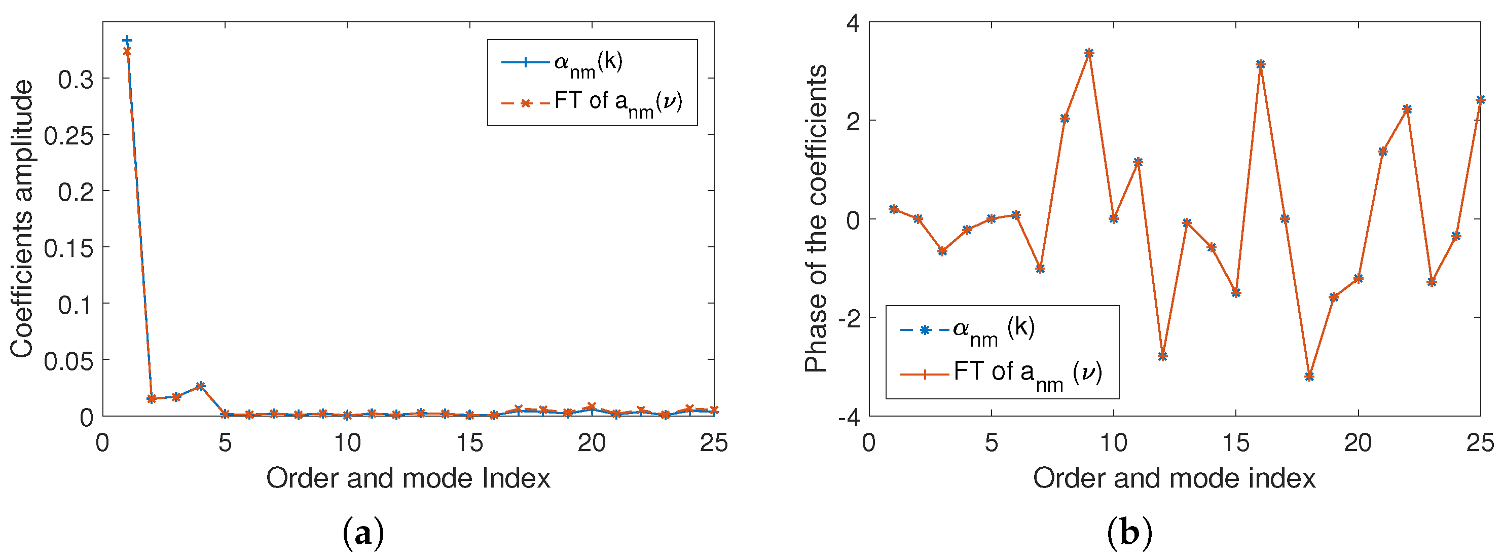
We use a narrow band signal at 1200 Hz to test if our proposed method can obtain time domain spherical harmonic coefficients a n m ( ν ) correctly with (26). In (11), we give the relationship between a n m ( ν ) and α n m ( k ) . We compare the Fourier transformation result of our obtained time domain spherical harmonic coefficients FT { a n m ( ν ) } with the desired frequency domain spherical harmonic coefficients α n m ( k ) , obtained by Equation (4) in frequency domain. Fourier transformations use J = 1024 points. We do not compare the phase of these coefficients since the group delay of the time domain method and the frequency domain method is different. Instead, we compare the phase difference, given by α n m ( k ) α n ( m 1 ) ( k ) . The results of both amplitude and phase difference are shown in Figure 5.
In Figure 5 we see that there is little to no difference on both amplitude and phase difference between the Fourier Transformed time domain coefficients and the frequency domain coefficients over all the order and modes. Thus, our proposed time domain method successfully obtained the time domain spherical harmonic coefficients, which can be related to the frequency domain coefficients by Fourier transformation.
Next, we compare the coefficients over different frequencies with a wide band test signal within the frequency limited of [ 20 , 1300 ] Hz. In Figure 6, we show the comparison of amplitude at F T { a 00 ( ν ) } and α 00 ( k ) , F T { a 11 ( ν ) } and α 11 ( k ) , and F T { a 31 ( ν ) } and α 31 ( k ) over frequencies respectively while Figure 7 shows the phase difference.
A huge error is observed in Figure 6a at the 46 th frequency bin. This error is due to that there is a Bessel zero of the zeroth order at this frequency bin (around 1072 Hz). We see the frequency domain spherical harmonic coefficients α 00 ( k ) has a much higher amplitude, while our proposed method suppressed the amplitude at this certain frequency bin. Meanwhile, we can see in Figure 6 and Figure 7 that the error at a 31 ( ν ) is higher compared to the other two modes. As order increases, the error increases. This error can be decreased by applying more microphones on the array. We also obtain a non-negligible error before the 30 th frequency bin of the coefficients amplitude for ( n , m ) = ( 3 , 1 ) in Figure 6c and Figure 7c. This error is because our time domain proposed method and conventional frequency domain method have different processing on suppressing Bessel zeros. During the reconstruction process, the high pass property of spherical Bessel function removes the information at this frequency bin. Thus, this error will not influence the reconstruction of the sound field.

5.2. Sound Pressure Comparison at a Point Of Interest

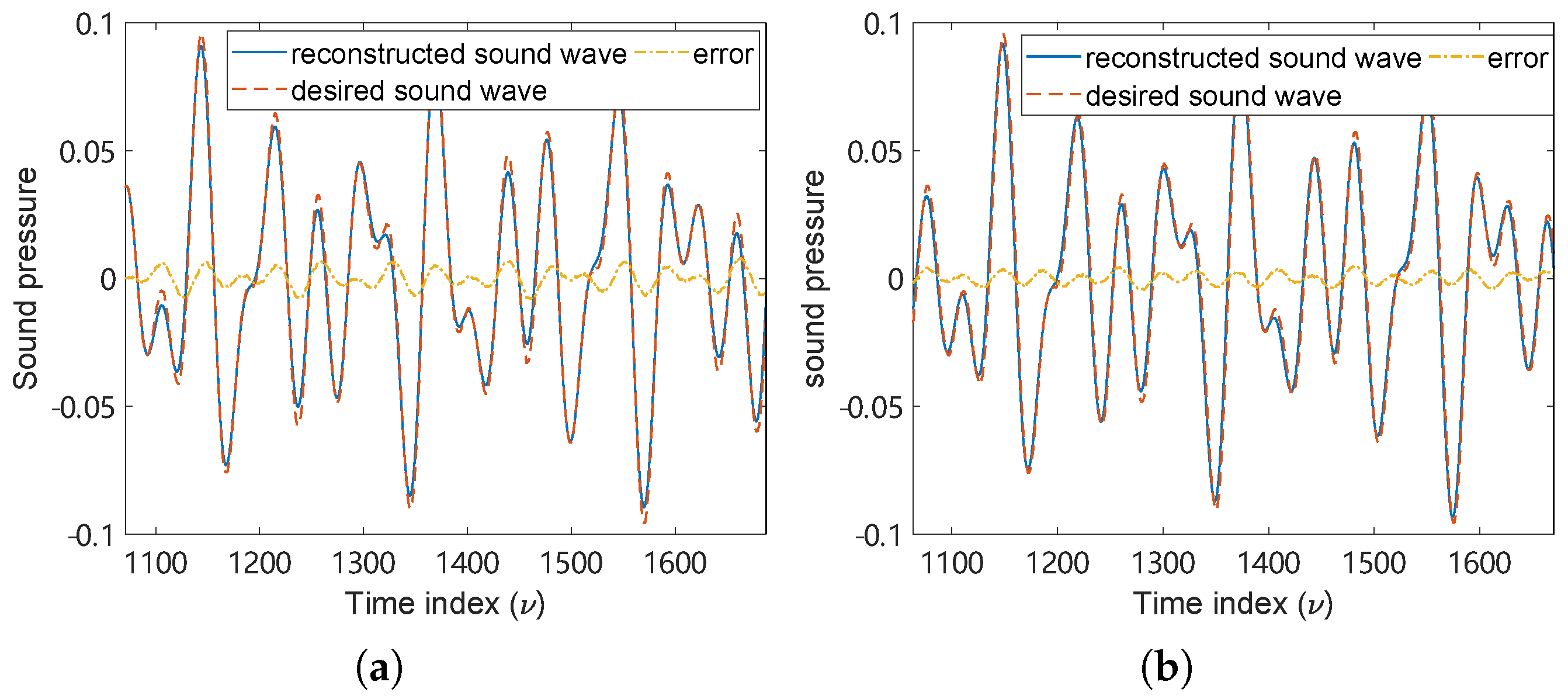
In this section, we reconstruct the sound field with the captured time domain spherical harmonic coefficients at a point in the region of interest, and compare it with the desired sound field at the same point of interest. We use a signal containing three frequency components of 600 Hz, 850 Hz, and 1300 Hz. Figure 8 shows the desired sound pressure and the reconstructed sound pressure calculated by a n m ( ν ) at the point [ 0.13 , 0.07 , 0.02 ] m and [ 0.03 , 0.01 , 0.1 ] m inside the region of interest in time domain. The desired sound field has been manually delayed for 272 samples to match the group delay of the reconstructed sound field, where the details of this delay will be shown in Section 5.5.
We note here that when reconstructing the sound-field with (6), we face the problem that at a point x = ( r , θ , ϕ ) where the radius r is very small, the filter p n ( ν , r ) , whose filter length dependents on r F s / c , is too short to perform efficient filtering. To overcome this problem, we up-sample the obtained a n m ( ν ) with a rate of R Q / r and construct corresponding p n ( ν , r ) with the same length of L p = 2 R Q F s / c + 1 . We then down-sample the resulting b n m ( ν , r ) with a rate of r / R Q to keep the sampling frequency consistent with F s . We can see that the obtained a n m ( ν ) by our proposed method can successfully reconstruct the sound pressure at a point inside the region of interest with a tolerable error. This supports that our time domain coefficients contain certain spatial information of the sound field that the sound pressure at an arbitrary point inside the region of interest can be properly calculated with the measurements only being taken on the boundary of the region.

5.3. Sound Field Comparison over a Plane

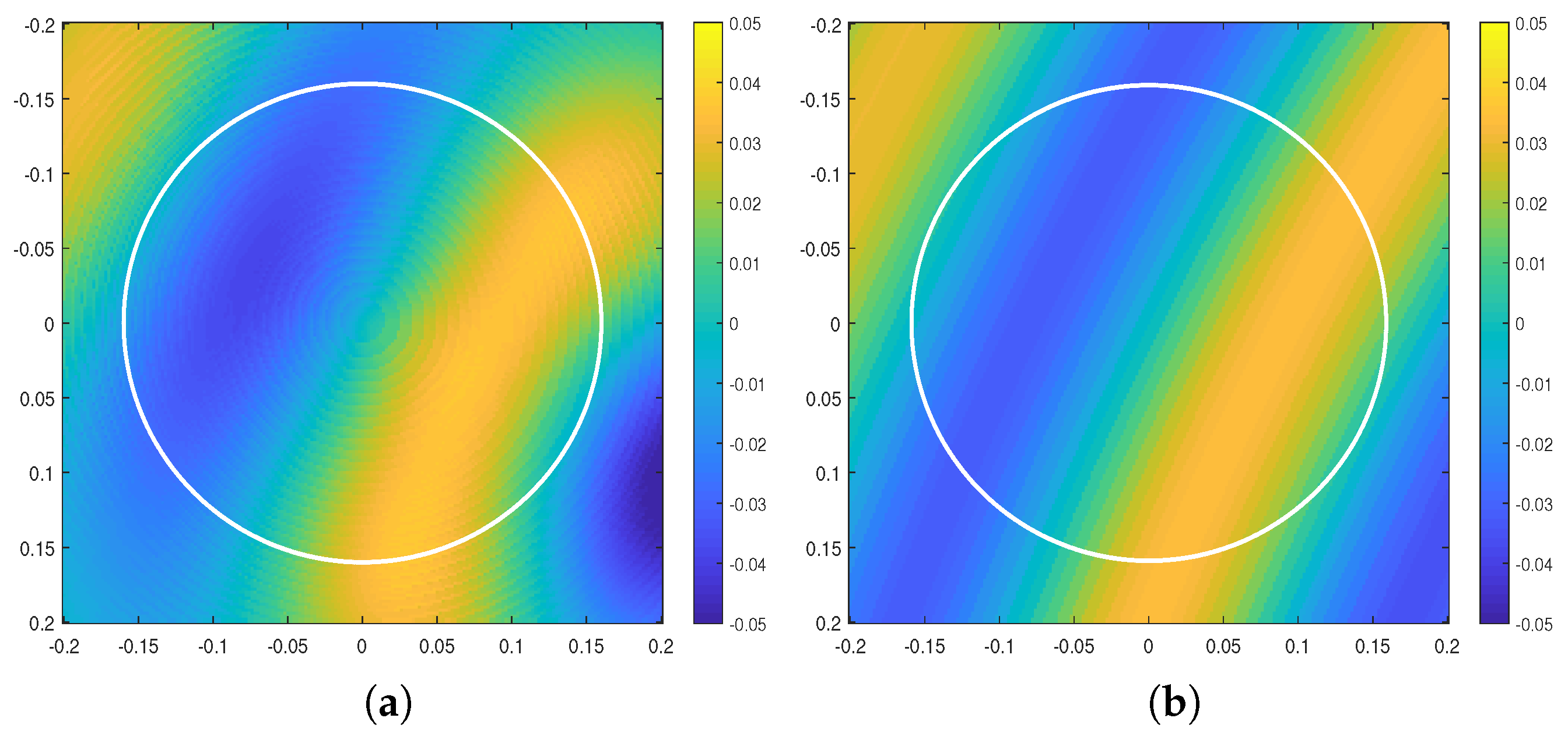
To further evaluate our method on reconstructing sound field over space, we now reconstruct the sound field by a n m ( ν ) over a plane. We use a narrow band signal of 1200Hz here that the sound field in the region of interest is simple and clearly understood. Although the sound field is reconstructed over time, a 2D plot can only show the result of one time index. Figure 9 shows the reconstructed sound field and the desired sound field over the plane parallel to the x-y plane, with z = 0.02 m at t = 0.3 s. The 272 samples group delay is manually fixed and will be discussed later in the next subsection.
The white line in Figure 9 bounds the region of interest. We can see that the reconstructed sound field inside this region in Figure 9a is roughly the same as the desired sound field in Figure 9b. This confirms that the coefficients recorded by our proposed method are able to capture the sound field inside the region of interest.

5.4. Sound Field Error Estimation over The Region

To evaluate the reconstructed sound field over time, we calculate the instantaneous average squared spatial error over time, which is defined by
e ( ν ) Ω S r ( x , ν ) S d ( x , ν ) 2 Ω .
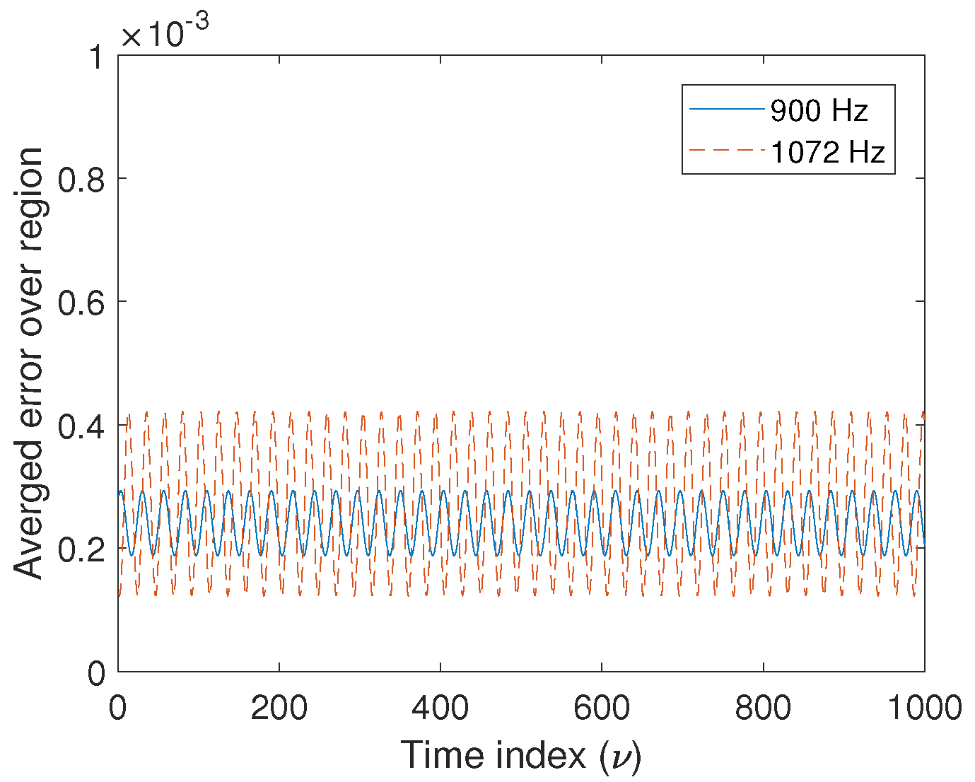
Figure 10 shows how the error fluctuates with time in a tolerable range (no more than 5 × 10 4 ) with a 900 Hz tone and a 1072 Hz tone. We have already observed in Figure 8 that the error of the sound pressure at a point of interest is proportional to the desired sound pressure. We observe the same trend when we evaluate the error over the region that the error increases when the sound field inside the region of interest is at peak amplitude. We also observe in Figure 10 that the error with 1072 Hz signal is higher than 900 Hz signal. This is due to that there is a Bessel zero of the zeroth order ( j 0 ( k r ) ) at 1072 Hz in the proposed spatial ANC system. Hence, the amplitude of a 00 ( ν ) is suppressed by the proposed method, leading to a higher error in reconstructing the sound field.

5.5. Processing Delay Analysis

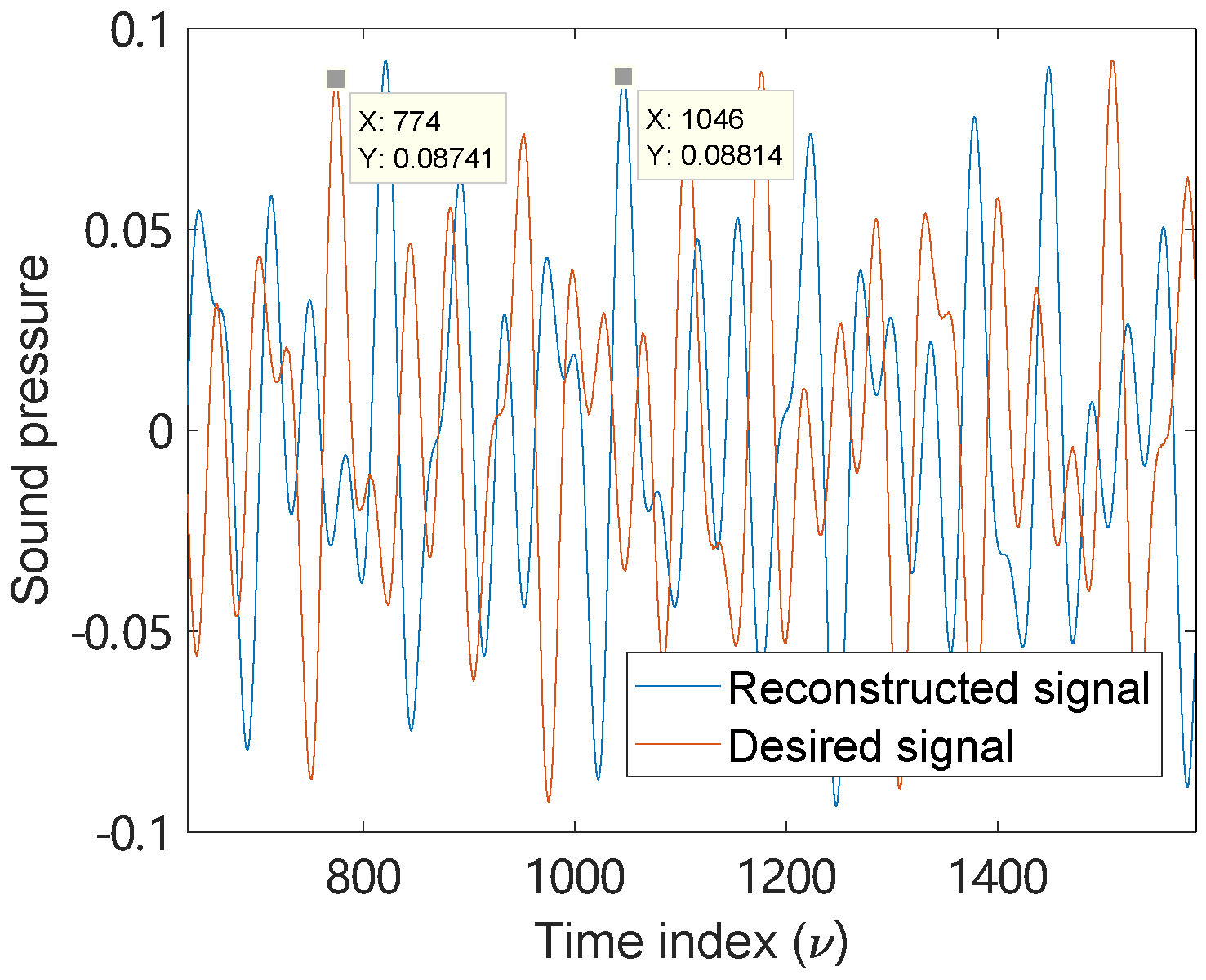
In this section, we indicate the group delay of our method. Figure 11 shows the desired sound pressure and the reconstructed sound pressure of a signal containing three frequency components of [ 600 , 850 , 1300 ] Hz at the point [ 0.13 , 0.07 , 0.02 ] m. We can obtain from Figure 11 that the processing delay of the system is 1046 774 = 272 samples, which equals to L + R Q F s / c . The L samples of the delay is from the group delay of the proposed filter ρ n ( ν , R Q ) , while R Q F s / c is the delay introducing by the Legendre function within filter p n ( ν , r ) to reconstruct the sound pressure at a point with the time domain spherical harmonic coefficients. Comparing to a conventional frequency domain scenario with 512 frame-size and 75 % of overlap Short Time Fourier transformation, which refers to a 2048 samples of delay [43], our proposed method can significantly reduce the processing delay.
Comparing to one of the start-of-art frequency domain spherical harmonic filter designs [44], which states a 75 ms delay with a 900 sample long filter, our method can achieve a 972 samples (20.25 ms with 48k Hz sampling frequency) delay with the same length of filter. Meanwhile, as our method is processed in time domain, there is nothing to stop us from doing a sample by sample signal processing instead of frame based signal processing. This sample based processing considerably extends the application of spherical harmonic analysis.

6. Conclusions

In this paper, a time domain spherical harmonic analysis method for spatial sound field recording over 3D space has been developed with the goal to minimize processing delay. This favours the specific application of spatial ANC. With the proposed FIR filter design, the time domain spherical harmonic coefficients can be obtained from the sound pressure measurements of an open spherical microphone array. The filters are designed based on the inverse of the Legendre function. Additionally, the filters are modified with considerations of stability and practical implementation. We have provided simulation results proving the validity of the proposed method.
We note that by obtaining the proposed time domain spherical harmonic coefficients, the desired sound field can be efficiently captured and reconstructed over space. The proposed time domain spherical harmonic coefficients can be related to the conventional frequency domain coefficients, where both have the same location independent property. The proposed method has the prominent advantage of lower delay since it is developed in the time domain without the introduction of a Fourier transformation or inverse Fourier transformation. Furthermore, the proposed time domain filtering method can support sample based signal processing instead of frame based, which indicates that the frame size can be one sample if necessary. As a result, we consider the proposed time domain spherical harmonic analysis method to be highly suitable for a spatial ANC system where accurate spatial recording with low delay is desired.
The most important future work is practically introducing the proposed spatial recording method to a spatial ANC system. Currently the proposed method utilizes open spherical microphone arrays, where the difficulties of constructing this array limit the potential applications. Hence, applying the proposed method to alternative optimised open microphone arrays is another direction for future work.

Author Contributions

Conceptualization, H.S., T.D.A. and P.N.S.; Funding acquisition, T.D.A. and P.N.S.; Investigation, H.S.; Methodology, H.S., T.D.A. and P.N.S.; Project administration, T.D.A.; Supervision, T.D.A. and P.N.S.; Validation, H.S.; Writing—original draft, H.S.; Writing—review and editing, T.D.A. and P.N.S. All authors have read and agreed to the published version of the manuscript.

Funding

This work is funded by Australian Research Council (ARC) grant DP180102375.

Institutional Review Board Statement

Not applicable.

Informed Consent Statement

Not applicable.

Data Availability Statement

No applicable.

Conflicts of Interest

The authors declare no conflict of interest.

Abbreviations

The following abbreviations are used in this manuscript:
ANCActive noise control
3DThree-dimensional
IFFTInverse fast fourier transform
FIRFinite impulse response
SNRSignal to noise ratio

Appendix A. Proof of Equation (9)

We have the Fourier relationship between the spherical Bessel function j n ( k r ) and the Legendre function P n ( t ) given by [45]
e i k r t j n ( k r ) d k = π i n P n ( t ) .
With (A1), p n ( t , r ) in (8) can be express as
p n ( t , r ) = c i n 2 π r j n ( k r ) e i t c k r r d k r = c 2 r P n ( t c r ) r c t r c 0 ± t > r c .
This completes the prove of (9).

References

  1. Ward, D.B.; Abhayapala, T.D. Reproduction of a plane-wave sound field using an array of loudspeakers. IEEE Trans. Speech Audio Process. 2001, 9, 697–707. [Google Scholar] [CrossRef] [Green Version]
  2. Abhayapala, T.D.; Ward, D.B. Theory and design of high order sound field microphones using spherical microphone array. In Proceedings of the IEEE International Conference on Acoustics, Speech, and Signal Processing, Orlando, FL, USA, 13–17 May 2002; Volume 2, pp. 1949–1952. [Google Scholar]
  3. Rafaely, B. Analysis and design of spherical microphone arrays. IEEE Trans. Speech Audio Process. 2004, 13, 135–143. [Google Scholar] [CrossRef]
  4. Park, M.; Rafaely, B. Sound-field analysis by plane-wave decomposition using spherical microphone array. J. Acoust. Soc. Am. 2005, 118, 3094–3103. [Google Scholar] [CrossRef]
  5. Zuo, H.; Samarasinghe, P.N.; Abhayapala, T.D.; Dickins, G. Spatial sound intensity vectors in spherical harmonic domain. J. Acoust. Soc. Am. 2019, 145, EL149–EL155. [Google Scholar] [CrossRef] [PubMed]
  6. Epain, N.; Jin, C.T. Spherical harmonic signal covariance and sound field diffuseness. IEEE/ACM Trans. Audio Speech Lang. Process. (TASLP) 2016, 24, 1796–1807. [Google Scholar] [CrossRef] [Green Version]
  7. Koretz, A.; Rafaely, B. Dolph–Chebyshev beampattern design for spherical arrays. IEEE Trans. Signal Process. 2009, 57, 2417–2420. [Google Scholar] [CrossRef]
  8. Gover, B.N.; Ryan, J.G.; Stinson, M.R. Microphone array measurement system for analysis of directional and spatial variations of sound fields. J. Acoust. Soc. Am. 2002, 112, 1980–1991. [Google Scholar] [CrossRef] [PubMed]
  9. Argentieri, S.; Danes, P.; Soueres, P. Modal analysis based beamforming for nearfield or farfield speaker localization in robotics. In Proceedings of the 2006 IEEE/RSJ International Conference on Intelligent Robots and Systems, Beijing, China, 9–15 October 2006; IEEE: Piscataway, NJ, USA, 2006; pp. 866–871. [Google Scholar]
  10. Birnie, L.; Abhayapala, T.D.; Chen, H.; Samarasinghe, P.N. Sound Source Localization in a Reverberant Room Using Harmonic Based Music. In Proceedings of the ICASSP 2019–2019 IEEE International Conference on Acoustics, Speech and Signal Processing (ICASSP), Brighton, UK, 12–17 May 2019; IEEE: Piscataway, NJ, USA, 2019; pp. 651–655. [Google Scholar]
  11. Spors, S.; Buchner, H. An approach to massive multichannel broadband feedforward active noise control using wave-domain adaptive filtering. In Proceedings of the IEEE Workshop on Applications of Signal Processing to Audio and Acoustics, New Paltz, NY, USA, 21–24 October 2007; pp. 171–174. [Google Scholar]
  12. Zhang, J.; Abhayapala, T.D.; Zhang, W.; Samarasinghe, P.N.; Jiang, S. Active Noise Control Over Space: A Wave Domain Approach. IEEE/ACM Trans. Audio Speech Lang. Process. (TASLP) 2018, 26, 774–786. [Google Scholar] [CrossRef]
  13. Cassina, L.; Fredianelli, L.; Menichini, I.; Chiari, C.; Licitra, G. Audio-visual preferences and tranquillity ratings in urban areas. Environments 2018, 5, 1. [Google Scholar] [CrossRef] [Green Version]
  14. Kuo, S.M.; Morgan, D.R. Active Noise Control Systems: Algorithms and DSP Implementations; John Wiley & Sons, Inc.: Hoboken, NJ, USA, 1995. [Google Scholar]
  15. Baumgartner, R.; Pomberger, H.; Frank, M. Practical implementation of radial filters for ambisonic recordings. In Proceedings of the ICSA 2011, Detmold, Germany, 10–13 November 2011. [Google Scholar]
  16. Moreau, S.; Daniel, J.; Bertet, S. 3D sound field recording with higher order ambisonics–Objective measurements and validation of a 4th order spherical microphone. In Proceedings of the 120th Convention of the AES, Paris, France, 20–23 May 2006; pp. 20–23. [Google Scholar]
  17. Zotter, F. A linear-phase filter-bank approach to process rigid spherical microphone array recordings. In Proceedings of the 5th International Conference on Electrical, Electronic and Computing Engineering, Palić, Serbia, 11–14 June 2018. [Google Scholar]
  18. Sun, H.; Abhayapala, T.D.; Samarasinghe, P.N. Time Domain Spherical Harmonic Analysis for Adaptive Noise Cancellation over a Spatial Region. In Proceedings of the IEEE International Conference on Acoustics, Speech and Signal Processing (ICASSP), Brighton, UK, 12–17 May 2019; IEEE: Piscataway, NJ, USA, 2019; pp. 516–520. [Google Scholar]
  19. Chen, H.; Abhayapala, T.D.; Zhang, W. Theory and design of compact hybrid microphone arrays on two-dimensional planes for three-dimensional soundfield analysis. J. Acoust. Soc. Am. 2015, 138, 3081–3092. [Google Scholar] [CrossRef]
  20. Abhayapala, T.D.; Gupta, A. Spherical harmonic analysis of wavefields using multiple circular sensor arrays. IEEE Trans. Audio Speech Lang. Process. 2010, 18, 1655–1666. [Google Scholar] [CrossRef]
  21. Sun, H.; Abhayapala, T.D.; Samarasinghe, P.N. Active Noise Control Over 3D Space with Multiple Circular Arrays. In Proceedings of the 2019 IEEE Workshop on Applications of Signal Processing to Audio and Acoustics (WASPAA), New Paltz, NY, USA, 20–23 October 2019; IEEE: Piscataway, NJ, USA, 2019; pp. 135–139. [Google Scholar]
  22. Bilbao, S.; Ahrens, J.; Hamilton, B. Incorporating source directivity in wave-based virtual acoustics: Time-domain models and fitting to measured data. J. Acoust. Soc. Am. 2019, 146, 2692–2703. [Google Scholar] [CrossRef] [PubMed]
  23. Farina, A.; Capra, A.; Chiesi, L.; Scopece, L. A spherical microphone array for synthesizing virtual directive microphones in live broadcasting and in post production. In Proceedings of the Audio Engineering Society Conference: 40th International Conference: Spatial Audio: Sense the Sound of Space, Tokyo, Japan, 8–10 October 2010; Audio Engineering Society: New York, NY, USA, 2010. [Google Scholar]
  24. Mabande, E.; Schad, A.; Kellermann, W. A time-domain implementation of data-independent robust broadband beamformers with lowfilter order. In Proceedings of the 2011 Joint Workshop on Hands-free Speech Communication and Microphone Arrays, Edinburgh, UK, 30 May–1 June 2011; IEEE: Piscataway, NJ, USA, 2011; pp. 81–85. [Google Scholar]
  25. Simón Gálvez, M.F.; Elliott, S.J.; Cheer, J. Time domain optimization of filters used in a loudspeaker array for personal audio. IEEE/ACM Trans. Audio Speech Lang. Process. (TASLP) 2015, 23, 1869–1878. [Google Scholar] [CrossRef]
  26. Nelson, P.A.; Elliott, S.J. Active Control of Sound; Academic Press: Cambridge, MA, USA, 1991. [Google Scholar]
  27. Long, G.; Ling, F.; Proakis, J.G. The LMS algorithm with delayed coefficient adaptation. IEEE Trans. Acoust. Speech Signal Process. 1989, 37, 1397–1405. [Google Scholar] [CrossRef]
  28. Long, G.; Ling, F.; Proakis, J.G. Corrections to ‘The LMS algorithm with delayed coefficient adaptation’. IEEE Trans. Signal Process. 1992, 40, 230–232. [Google Scholar] [CrossRef]
  29. Lösler, S.; Zotter, F. Comprehensive radial filter design for practical higher-order Ambisonic recording. In Proceedings of the Fortschritte der Akustik DAGA, Nuremberg, Germany, 16–19 March 2015; pp. 452–455. [Google Scholar]
  30. Jin, C.T.; Epain, N.; Parthy, A. Design, optimization and evaluation of a dual-radius spherical microphone array. IEEE/ACM Trans. Audio Speech Lang. Process. 2013, 22, 193–204. [Google Scholar] [CrossRef]
  31. Politis, A.; Gamper, H. Comparing modeled and measurement-based spherical harmonic encoding filters for spherical microphone arrays. In Proceedings of the 2017 IEEE Workshop on Applications of Signal Processing to Audio and Acoustics (WASPAA), New Paltz, NY, USA, 15–18 October 2017; IEEE: Piscataway, NJ, USA, 2017; pp. 224–228. [Google Scholar]
  32. Balmages, I.; Rafaely, B. Open-sphere designs for spherical microphone arrays. IEEE Trans. Audio Speech Lang. Process. 2007, 15, 727–732. [Google Scholar] [CrossRef]
  33. Chardon, G.; Kreuzer, W.; Noisternig, M. Design of spatial microphone arrays for sound field interpolation. IEEE J. Sel. Top. Signal Process. 2015, 9, 780–790. [Google Scholar] [CrossRef] [Green Version]
  34. Ueno, N.; Koyama, S.; Saruwatari, H. Sound field recording using distributed microphones based on harmonic analysis of infinite order. IEEE Signal Process. Lett. 2017, 25, 135–139. [Google Scholar] [CrossRef]
  35. Poletti, M.; Abhayapala, T.D.; Teal, P.D. Time domain description of spatial modes of 2D and 3D free-space greens functions. In Proceedings of the Audio Engineering Society Conference: 2016 AES International Conference on Sound Field Control, Guildford, UK, 18–20 July 2016; Audio Engineering Society: New York, NY, USA, 2016. [Google Scholar]
  36. Winter, F.; Hahn, N.; Spors, S. Time-domain realisation of model-based rendering for 2.5 D local wave field synthesis using spatial bandwidth-limitation. In Proceedings of the 2017 25th European Signal Processing Conference (EUSIPCO), Kos, Greece, 28 August–2 September 2017; IEEE: Piscataway, NJ, USA, 2017; pp. 688–692. [Google Scholar]
  37. Hahn, N.; Spors, S. Time-Domain Representations of a Plane Wave with Spatial Band-Limitation in the Spherical Harmonics Domain. In Proceedings of the Meeting of the German Acoustical Society (DAGA), Rostock, Germany, 18–21 March 2019. [Google Scholar]
  38. Yan, S.; Sun, H.; Ma, X.; Svensson, U.P.; Hou, C. Time-domain implementation of broadband beamformer in spherical harmonics domain. IEEE Trans. Audio Speech Lang. Process. 2010, 19, 1221–1230. [Google Scholar]
  39. Ren, W.; Chen, H.; Gao, W. On the design of time-domain implementation structure for steerable spherical modal beamformers with arbitrary beampatterns. Appl. Acoust. 2017, 122, 146–151. [Google Scholar] [CrossRef]
  40. Arfken, G.B.; Weber, H.J. Mathematical Methods for Physicists; Academic Press: San Diego, CA, USA, 1999. [Google Scholar]
  41. Williams, E.G. Fourier Acoustics: Sound Radiation and Nearfield Acoustical Holography; Elsevier: Amsterdam, The Netherlands, 1999. [Google Scholar]
  42. Homeier, H.H.H.; Steinborn, E.O. Some properties of the coupling coefficients of real spherical harmonics and their relation to Gaunt coefficients. J. Mol. Struct. THEOCHEM 1996, 368, 31–37. [Google Scholar] [CrossRef]
  43. Oppenheim, A.V. Discrete-Time Signal Processing; Pearson Education India: Tamil Nadu, India, 1999. [Google Scholar]
  44. Langrenne, C.; Bavu, E.; Garcia, A. A linear phase IIR filterbank for the radial filters of ambisonic recordings. In Proceedings of the EAA Spatial Audio Signal Processing Symposium, Paris, France, 6–7 September 2019. [Google Scholar]
  45. Chang, H.P.; Sarkar, T.K.; Pereira-Filho, O.M. Antenna pattern synthesis utilizing spherical Bessel functions. IEEE Trans. Antennas Propag. 2000, 48, 853–859. [Google Scholar] [CrossRef] [Green Version]
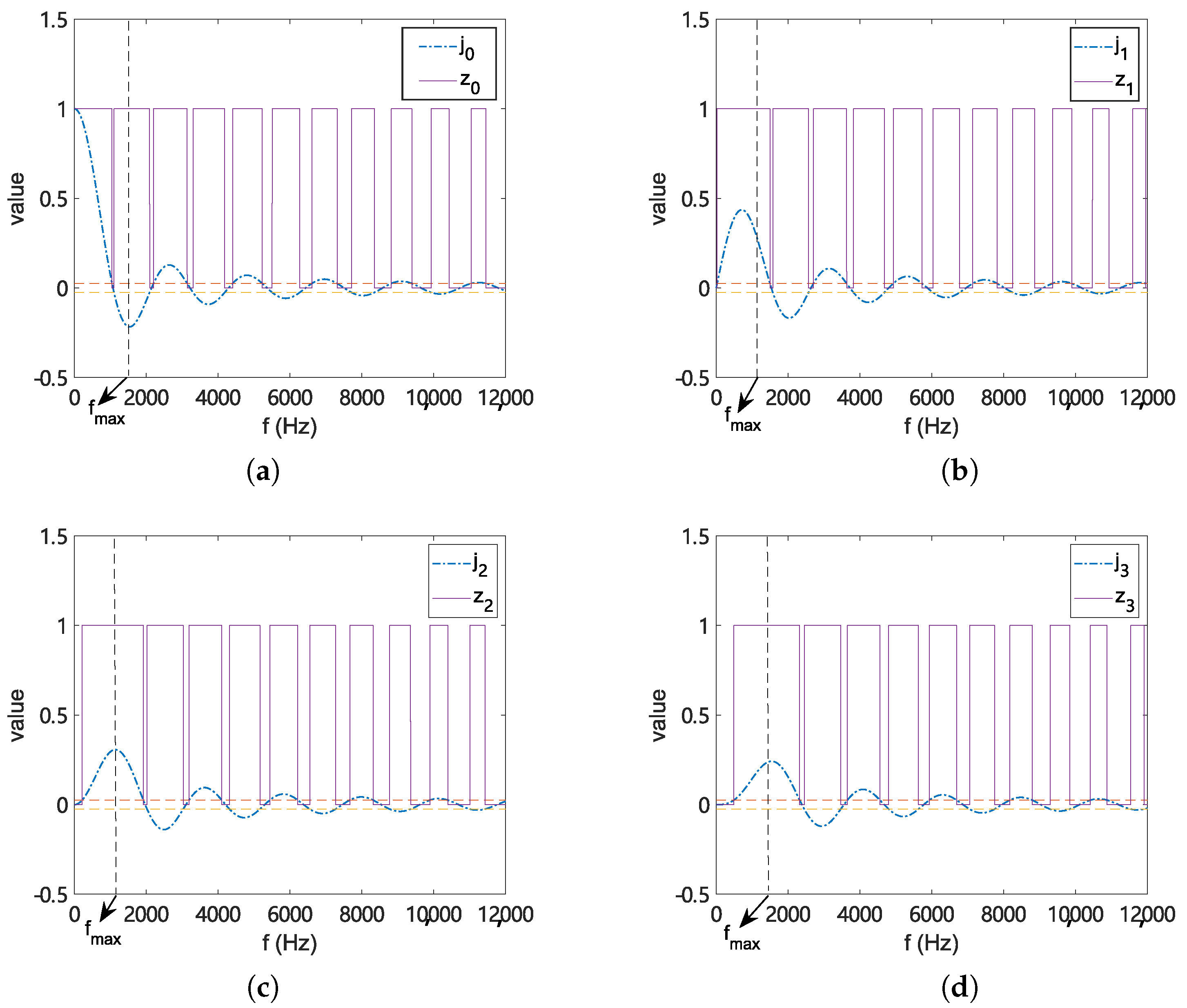
Figure 1. The spherical Bessel function j n ( 2 π f R Q / c ) and Z ^ n ( f ) of order (a) n = 0 , (b) n = 1 , (c) n = 2 , (d) n = 3 with f max 1360 Hz, ϵ = 1 / 40 , R Q = 0.16 m and c = 343 m/s.
Applsci 11 01074 g001
Figure 2. Frequency response of up to 4-th order of the pre-designed order dependent FIR filter ρ n ( ν , R Q ) with z n ( ν ) frequency truncated at (a) f 1 , (b) f 2 (c) f 3 .
Applsci 11 01074 g002
Figure 3. Error of ρ n ( ν , R Q ) p n ( ν , R Q ) with length L = (a) 25, (b) 250 (c) 2500.
Applsci 11 01074 g003
Figure 4. Time representation of the pre-designed order dependent FIR filter ρ n ( ν , R Q ) with length L = (a) 25, (b) 250 (c) 2500.
Applsci 11 01074 g004
Figure 5. (a) Amplitude and (b) phase difference comparison between the Fourier Transform of the time domain spherical harmonic coefficients a n m ( ν ) and frequency domain spherical harmonic coefficients α n m ( k ) at a single frequency f = 1200 Hz.
Applsci 11 01074 g005
Figure 6. Amplitude comparison between the Fourier Transform of the time domain spherical harmonic coefficients a n m ( ν ) and frequency domain spherical harmonic coefficients α n m ( k ) at mode (a) 00, (b) 11 and (c) 31 with a white Gaussian noise.
Applsci 11 01074 g006
Figure 7. Phase difference comparison between the Fourier Transform of the time domain spherical harmonic coefficients a n m ( ν ) and frequency domain spherical harmonic coefficients α n m ( k ) at mode (a) 00, (b) 11 and (b) 31 with a white Gaussian noise.
Applsci 11 01074 g007
Figure 8. Comparison between reconstructed sound pressure and desired sound pressure at the point (a) ( 0.13 , 0.07 , 0.02 ) m and (b) ( 0.03 , 0.01 , 0.1 ) m.
Applsci 11 01074 g008
Figure 9. Comparison between (a) reconstructed sound field and (b) desired sound field at the horizontal plane with a height of z = 0.02 m.
Applsci 11 01074 g009
Figure 10. Instantaneous region averaged squared spatial error of the proposed method for sound field reconstruction over space at 900 Hz and 1072 Hz (Bessel zero).
Applsci 11 01074 g010
Figure 11. Delay analysis between the desired signal and the reconstructed signal at a point inside the region of interest.
Applsci 11 01074 g011
Table 1. The first four order of w ( n ) to derive z ^ n ( ν ) with f max 2047 Hz, ϵ = 1 / 40 , R Q = 0.16 m and c = 343 m/s.
n (Order)w 1 ( n ) w 2 ( n ) w 3 ( n ) w 4 ( n )
00.00090.13690.14390.2680
10.00330.19570.20590.2680
20.02760.25090.36430.2680
30.06400.2680--
Publisher’s Note: MDPI stays neutral with regard to jurisdictional claims in published maps and institutional affiliations.