Featured Application
MAuth-CAN is a new CAN authentication mechanism, and the proposed CAN model and verification techniques are useful to analyze timing properties of CAN applications.
Abstract
The Controller Area Network (CAN) is the most common network system in automotive systems. However, the standardized design of a CAN protocol does not consider security issues, so it is vulnerable to various security attacks from internal and external electronic devices. Recently, in-vehicle network is often connected to external network systems, including the Internet, and can result in an unwarranted third-party application becoming an attack point. Message Authentication CAN (MAuth-CAN) is a new centralized authentication for CAN system, where two dual-CAN controllers are utilized to process message authentication. MAuth-CAN is designed to provide an authentication mechanism as well as provide resilience to a message flooding attack and sustainably protect against a bus-off attack. This paper presents formal techniques to guarantee critical timing properties of MAuth-CAN, based on model checking, which can be also used for safety certificates of vehicle components, such as ISO 26262. Using model checking, we prove sufficient conditions that MAuth-CAN is resilient and sustainable against message flooding and bus-off attacks and provide two formal models of MAuth-CAN in timed automata that are applicable for formal analysis of other applications running on CAN bus. In addition, we discuss that the results of model checking of those properties are consistent with the experiment results of MAuth-CAN implementation.
1. Introduction
Advanced digital control technology provides more convenience, safety, and predictability to automotive systems. Recently, many vehicles would not only make use of local sensors, but also cooperate with other vehicles and infrastructures, such as the Intelligent Transport System (ITS). For instance, Right-turn Collision Caution (RtCC) cooperating with infrastructures can alert drivers in a risky situation hidden when they would make right turn. ITS monitors the situation about oncoming vehicles and pedestrians around intersections or a corner with poor visibility from drivers where a vehicle would make a right turn. It cooperates with the vehicle via road-to-vehicle communication so the information on potential approaching risk is conveyed by vehicle-to-vehicle communication with audio and visual alerts to warn the driver, and when necessary, the driver is alerted about the approach risk. The infrastructure uses a dedicated ITS frequency of 760 MHz for road-to-vehicle and vehicle-to-vehicle communication to gather information that cannot be obtained by vehicle sensors. In addition, various features, such as Communication Radar Cruise Control, Red Right Caution, and Emergency Vehicle Notification using network communication also helps drivers be more predictive against approaching risky situations so that their driving is safe and predictable.
However, the vehicle connecting to open networks can be vulnerable to security attacks. For instance, many studies such as [1,2,3,4,5,6] have shown that the adversary is able to easily access an in-vehicle network from the outside and control vehicles. Once an adversary compromises an ECU, it disguises itself as a normal node, breaches to other ECUs, and controls and disrupts normal driving function. In addition, DoS (Denial of Service) is also one of the most common attacks that exhausts data processing and communication resources.
To prevent the masquerade attack to a vehicle network, the most popular defense technologies are intrusion detection systems (IDS) and authentication systems. Most proposed IDS techniques are not, however, fast enough to protect the attack, i.e., the adversary can compromise the vehicle system before IDS detects the attack [7,8,9,10,11,12,13]. In order to address these issues, many authentication protocols have been studied, such as [14,15,16,17,18,19,20]. These works can be classified into two categories: authentication using group keys [14,15,16,17] or authentication using pairwise keys [18,19,20]. In case that CAN uses a group key for message authentication, the group key could be exploited if any node using the group key is compromised. In case of authentication using pairwise keys, CAN bus can be overflowed by authentication tags (e.g., message authentication code) if CAN bus uses a basic pairwise key-based authentication method where every destination node requires a unique authentication tag for verification of a CAN message. Thus, the work [18,19,20] adopts a centralized node-based authentication to deal with the overflow issue.
However, this centralized node-based authentication has two problems. First, the authentication by a centralized node can be delayed by DoS attack on the centralized node. Second, in case of the centralized authentication, the authenticator could miss a message if it is too slow to process every message. Thus, it should be guaranteed that the authentication is complete on time no matter how often the adversary sends an attack message.
To address the above problems, Jo et al. have proposed a new authentication protocol, named MAuth-CAN (Message Authentication-CAN), in [21]. MAuth-CAN uses an ECU node dedicated to authenticating each message over the CAN bus by using pairwise keys. For sharing the authentication result with other ECUs, the authenticator uses an authentication-fail error (AFR) message. The authentication fail report (i.e., AFR message) is transmitted and gives alerts to other nodes only when a message is authenticated. This minimizes the communication overload caused by a centralized authentication because the authentication fail report is transmitted only when a message cannot pass authentication. In addition, Jo et al. addresses Bus-off Attacks (BoAs) by introducing their centralized message authentication to dual-CAN controllers. Under the adversary’s BoA to the authenticator, the AFR message from the authenticator can also be destroyed by the adversary, resulting in consecutive transmission errors. If the transmission error count of the authenticator steps over a threshold, it is enforced to leave CAN bus for a while and reset to recover the connection to CAN bus. Jo et al. adopts dual-CAN controllers for the authenticator to be more sustainable under BoA. Jo et al. [21] also showed that (1) MAuth-CAN is robust against the masquerade attack and BoA, (2) it requires approximately 46% less CAN bandwidth than a comparable protocol [19], and (3) it does not need to modify the current CAN controller to apply the CAN protocol.
However, they have not provided the proof of timing-related properties of MAuth-CAN that can be used for security proof and evidence for practical use of real applications. For instance, MAuth-CAN should prove that no adversary message is accepted by any node while authentication is in processing under DoS attack. It is related to a timeout for AFR, which delays message communication. Thus, it is necessary to check if such a timeout is bounded to check if the authentication delay meets the maximum acceptance communication delay.
In this paper, we show that the authentication of MAuth-CAN is resilient enough to prevent a masquerade attack for the given timing constraints and is sustainable under a DoS attack. In addition, we prove that the timeout for authentication can be bounded with respect to the message transmission time. In this paper, we apply formal methods of model checking to prove the timing properties of MAuth-CAN. We build formal models of CAN and MAuth-CAN using timed automata and perform model-checking to verify the critical timing properties of MAuth-CAN using UPPAAL SMC and UPPAAL MC. We present two formal models of CAN and MAuth-CAN. The first model abstracts MAuth-CAN by a producer-consumer model in terms of authenticator and attacker, so that it is proved that the authenticator in terms of a consumer addresses all attack messages from the attacker in terms of a producer. The second model details CAN in the level of MAC frame of the data link layer, so that the model of MAuth-CAN is shown to be valid in the data-link layer of CAN networking.
This paper presents sufficient conditions to ensure:
- The centralized authentication of MAuth-CAN never fails to make AFR messages reach individual ECUs within a specific bounded time,
- The authentication of MAuth-CAN can never be a victim of BoA.
The above conditions are relevant to (1) the size of reception queue of authenticator’s CAN controller, (2) the relation between authentication time and CAN bus transmission time, and (3) the number of CAN controllers of the authenticator.
This paper presents the following three contributions:
- In terms of MAuth-CAN security, it shows that MAuth-CAN is resilient and sustainable against a message flooding attack and bus-off attack under the specific conditions this paper provides;
- It presents a usage of formal methods to obtain certificates of safety and security standards and regulations, such as ISO (International Organization for Standardization) 26262;
- It presents new formal models of CAN bus at the level of MAC (Media Access Control) of the data link layer that can be useful for verification of properties of other applications running on CAN bus.
The rest of the paper is organized as follows: Section 2 discusses the related work. Section 3 presents the background theory of this work. Section 4 overviews MAuth-CAN, a centralized CAN authentication, two attack scenarios i.e., masquerade attack and BoA attack, and MAuth-CAN’s countermeasure to those attacks. Section 5 shows formal proof of our proposed sufficient conditions for MAuth-CAN resiliency to a masquerade attack and sustainability to BoA attack, using symbolic and statistical model checking techniques. Section 6 presents more results from the implementation of MAuth-CAN. In Section 7, we conclude this paper with the potential future work.
2. Related Work
In 2010, Koscher et al. were the first to demonstrate attacks on in-vehicle network using a real vehicle [1]. They introduced the CARSHARK tool, which makes it easy for an adversary to analyze and inject attack packets on in-vehicle network, i.e., CAN bus. After the first vehicle attack, many studies included new attack surfaces on an in-vehicle network [2,3,4,5,6]. To deal with these cyber-attacks on in-vehicle network, intrusion detection systems [7,8,9,10,11,12,13] and message authentication protocols [5,14,15,16,17,18,19,20,21] were studied.
In the work of [7,8,9,10], the transmission frequencies or sequences of CAN packets were used to detect the CAN traffic abnormality caused by in-vehicle network attacks. Recently, deep neural network (DNN) model-based intrusion detection systems that take transmission frequencies or sequences of CAN packets as input values have been proposed in [11,12]. However, these studies [7,8,9,10,11,12] cannot detect masquerade attacks by a compromised ECU because the compromised node can mimic the transmission frequencies or sequences of CAN packets to bypass intrusion detection algorithms.
To handle the masquerade attacks, Cho et al. proposed an ECU’s clock-based intrusion detection system [13]. In this study, a clock skew for each ECU is profiled as a hardware fingerprint, which is unique for every ECU, and this inimitable value is used to identify a masquerading ECU. However, this study cannot be used to deal with masquerade attacks using aperiodic CAN messages generated from aperiodic vehicle operations, such as auto-parking, lane keeping aid (LKA), and adaptive cruise control (ACC) functions. Furthermore, this clock-based intrusion detection can be defeated by the clock emulation attack proposed in [22].
To address the limitations of existing intrusion detection systems, message authentication protocols for in-vehicle network have been designed. In general, message authentication protocols can be divided into two categories: a group key-based authentication [14,15,16,17] and a central node-based authentication [18,19,20,21]. In the group key-based authentication studies [14,15,16,17], one group key shared by all ECUs is used to generate authentication tags such as message authentication code. However, these studies cannot also handle masquerade attacks because one group key could be accessed by a compromised node. In light of this, centralized node-based authentication studies have been presented in [18,19,20,21] for handling masquerade attacks by compromised ECUs. Since the centralized node-based authentication does not share one group key with all ECUs, a compromised ECU cannot access the authentication keys stored in other ECUs. However, the methods [18,19] cannot be applied into legacy vehicles because the CAN-controller must be modified to include new functions that do not follow the CAN-standard or incurs network overhead that exceeds the maximum capacity of the CAN bus. Furthermore, the protocol [20] also has limitation that several bytes of a CAN message is not included in the authentication value generation process.
To handle these issues of authentication protocols, Jo et al. presented an authentication report-based message authentication [21]. This protocol does not incur network overhead nor require CAN controller modification, but there is a message authentication delay caused by an authentication report message. Even though the work of [21] evaluated the authentication delay by using CAN development boards, there is no formal analysis about the delay which could affect real-time operations of vehicles. Thus, this paper puts the authentication delay of [21] into formal analysis using UPPAAL SMC and UPPAAL MC.
In addition, we did the several Arduino-based authentication tests, which are related to what-if analysis and robustness checking defined in [23], by measuring the authentication delay of [21] in the worst case scenarios to show that the authentication delay is bounded within a certain amount of time even when there are DoS attacks such as message flooding and bus-off attacks on CAN.
3. Preliminaries
In this section, we give the overall of our approach and overview our formal techniques, model checking, UPPAAL and CAN communication, prior to MAuth-CAN in the following section.
3.1. Our Approach
The CAN authentication in MAuth-CAN meets two goals: (1) No receiver can open any message that does not go through a centralized authentication of MAuth-CAN, (2) The CAN controller for message authentication is never enforced to leave CAN bus by consecutive and numerous transmission errors by intention.
In this paper, we show why MAuth-CAN never fails to meet the above goals. To simplify the above goals, we present sufficient conditions in theorems, which should be satisfied to meet the goals (Section 4.4, and then prove them by model checking (Section 5)). We use a high-level model of MAuth-CAN, where the reaction of the authenticator to the attack message is highlighted (Section 5.1). Then, using model checking, we prove that the authenticator of MAuth-CAN passes no attack message without verification even under even consecutive attacks if the sufficient conditions in Theorem 1 consisting of Lemma 1 and Lemma 2 are satisfied. We present a low-level formal model of MAuth-CAN in the MAC level of the data link layer of CAN, which is detailed enough to be able to reflect actual behaviors of CAN. This model ensures our verification is practical enough to provide valid proofs of security of MAuth-CAN (Section 5.2). Then, we prove Theorem 2 by proving Lemma 3, which is the essential property of MAuth-CAN assumed by Theorem 2. Finally, we show that our verification results are consistent with the actual implementation of MAuth-CAN (Section 6).
In the following subsection, we present our model method technique, model checking using UPPAAL.
3.2. Model Checking
Model checking is a rigorous verification method that presents a mathematical proof for a given property of the system. It accepts a system model and properties that the system model should satisfies. During verification, model checking explores all states of the system by taking every symbolic computational step and exhaustively check if every state satisfies given properties. Since model checking explores thoroughly all states of the system, it requires numerous time and memories. It is used to obtain guarantee of given properties of safety critical systems by mathematical proving techniques.
In this paper, we apply UPPAAL, a model checker, to prove MAuth-CAN’s properties. UPPAAL tool suite includes various analysis techniques such as symbolic model checking, statistical model checking, and simulation. Symbolic model checking of UPPAAL accepts timed automata (TA) [24] as modeling language and use CTL (Computational Tree Logic) for property specification. CTL in UPPAAL comprises path formulas and state formulas. A path formula consists of branch quantifiers and path quantifiers. A and E, branch quantifiers, denotes “all paths” and “any path”, respectively. □ and ♢, path quantifiers, represent “all states” and “exist a state”, respectively.
Let ϕ a state formula. A path formula along with a state formula is expressed by the grammar:
Using such a formula, reachability, safety and liveness properties can be formulated in UPPAAL. Reachability properties are expressed by the path formula E♢ϕ, meaning that a state satisfying ϕ is reachable.
φ ::= ϕ|A□ϕ|E□ϕ|A♢ϕ|E♢ϕ|ϕ1→ϕ2
Safety properties are formulated by the path formula A□. For example, A□ϕ requires that ϕ should be true in all reachable states. Meanwhile, E□ϕ denotes that there exists a maximal path such that ϕ is always true. A maximal path is a path that is either infinite or where the last state has no outgoing transitions [25]. Liveness properties are formulated by the path formula A♢ϕ, which means that there exists a state satisfying ϕ in all the branches, i.e., ϕ is eventually satisfied. One of useful formulas is the leads to or response property, which are written A□(ϕ→A♢ψ). That means that whenever ϕ happens, ψ should hold eventually [25]. For instance, whenever a message is sent, that should always be acknowledged.
UPPAAL SMC accepts a network of stochastic timed automata (NSTA). A model of network of timed automata in UPPAAL is redefined by a network of stochastic timed automata where the non-determinism of behavior in a timed automata model is refined by a probability distribution, so that the property for a given model is characterized by a probability that an event happens or a property holds.
The specification of UPPAAL SMC is based on Metric Interval Temporal Logic [26]. For an NSTA M, PM (ϕ) denotes the probability that a random run of M satisfies ϕ. The problem of checking PM (ϕ) ≥ p (p ∈ [0, 1]) is undecidable. For this reason, for the sub-logic of cost-bounded reachability problem PM(♢(x≤C) AP) ≥ p, where x is a clock, C is a time bound, and AP is a conjunction of predicates over the state of a NSTA, UPPAAL SMC approximates the answer using simulation-based algorithms [27]. In UPPAAL SMC, the following three types of questions can be answered:
- Probability estimation: What is the probability PM(♢(x≤C) AP) for a given M?
- Hypothesis testing: Is the probability PM(♢(x≤C) AP) for a given M greater or equal to p [0, 1]?
- Probability comparison: Is the probability PM(♢(x≤C)AP1) greater than the probability PM(♢(x≤C)AP2)?
PM(♢(x≤C)AP) is expressed by “P[⇐ C](<> AP)” in UPPAAL. This formula omits x from the original formula assuming that the global clock is used implicitly by formula. Besides, the following two forms of queries to simulate a given model:
- simulate [bound; N] {E1, E2, …, Ek}: Simulate a model and return results in E1, …, Ek expressions. N represents the number of simulations.
- E[bound; N] (min|max: expr): Simulate a model N rounds of which each precedes up to bound time units and return the min or max of the expression expr.
where bound is a time bound on the simulation, Ek is an expression that would be monitored and visualized.
In this paper, we use both UPPAAL and UPPAAL MC for proving properties of MAuth-CAN and simulating our model of MAuth-CAN. In Section 5, we present MAuth-CAN model of TA and various properties specification in CTL and verification results from UPPAAL.
3.3. CAN (Controller Area Network)
A Controller Area Network (CAN) is a de-facto standard for an in-vehicle network. Basically, once a node using CAN releases a message onto CAN bus, CAN broadcasts the message to all nodes, and the message is selectively picked up by an ECU that is one of message’s destinations. Table 1 shows the structure of the CAN packet frame.

Table 1.
CAN packet frame (Unit: bits).
Table 2 shows the individual frames of a CAN packet. Each node is given its own CAN ID, which plays a role as priority for CAN bus. Two or more nodes release messages into CAN bus at the same time, then one of them with the higher priority can transmit the message. In CAN bus, 0 (dominant bit) has a higher priority over 1 (recessive bit). That is, CAN controller permits 0 to flow over CAN bus rather than 1 when both are released at time same time. CAN causes various errors, such as bit, stuff, CRC, and ACK errors. Once a node on CAN bus encounters one of the errors, rest of nodes are informed the error simultaneously. Each node updates one of error counters, such as Receive Error Counter (REC) and Transmit Error Counter (TEC), according to error types error mode depending on error counter. For instance, a node transits into the passive error from the active error state when REC or TEC is over 126 (≥127). A node under the passive error state goes to bus-off state when TEC is over 255 (≥256), but the node is not driven to bus-off state by REC. Once a node is at bus-off state, it is enforced to leave the CAN bus for a specific time. TEC has different increasing and decreasing rates. Every time a transmission error happens, TEC increases by 8. Meanwhile, it decreases by 1 every time a transmission is successful.
Table 2.
Symbol and variable definitions.
4. MAuth-CAN
This section overviews MAuth-CAN, a new CAN authentication technology, and their properties for protection of masquerade attack and BoA. In addition, we formulate properties for model checking of MAuth-CAN. Prior to description of MAuth-CAN protocol and models, Table 2 defines symbols and variables for formal descriptions.
4.1. System and Adversary Assumptions
In this subsection, we provide the assumptions for CAN and adversary (attacker), in particular, their capability for defense and attack.
4.1.1. System Assumptions
First, the system dedicates to the authenticator an ECU with two CAN controllers for CAN message authentication. The dedicated ECU is assumed to be assigned to the highest priority CANID, which is open to anyone. Second, we assume that it is possible to compute the maximum acceptable communication delay for a given application running and communicating over CAN. Third, we assume that the ECU, i.e., the authenticator, for authentication is very hard for the attacker to compromise so as to drop the assumption that CAN is a victim of a single point failure (SPF) where all points lose a specific security once a point is compromised. This assumption can be achieved by applying lightweight tamper-resistance hardware such as SMART [28] and TrustLite [29] into the authenticator.
4.1.2. Adversary Assumptions
An adversary is subject to the following assumptions: First, any adversary reaches a node responsible for driving controls and can cause bad driving consequences. Second, two or more adversary nodes cannot perform DDoS (Distributed DoS), i.e., attacker cannot compromise more than one ECU node. Third, the information of CAN messages, such as source address, data, etc., transmitted on CAN bus can be fabricated, forged by adversary node. Fourth, the highest priority ID can be exploited by an adversary. Fifth, each ECU has a different CAN controller and the different number of the message receiving queues from the others. Sixth, each ECU is equipped with a single message buffer each for transmission and reception.
4.2. Attack Scenarios
4.2.1. Masquerade Attack
An adversary fabricates CAN messages with a normal CANID so that vehicle driving is illegally controlled by adversary’s control messages. For example, the compromised ECU can transmit a CAN message using the CANID of an ECU related to the engine to control the vehicle’s speed. According to [5], the CANID of 0x43F was transmitted by a compromised node to actuate the vehicle’s engine.
4.2.2. Denial of Service Leading to Bus-Off
Figure 1 describes a scenario of an adversary’s Denial of Service attack using BO. The adversary performs DoS attack with consecutive attack messages, in particular, while the authenticator needs to broadcast an authentication-fail report. When both the adversary and the authenticator attempt to send messages with the same identifier simultaneously, the AFR and the attack message collide with each other. As a result, the transmission error occurs and increases TEC on both sender and receiver. If the TEC of the authenticator goes behind the threshold of Passive Error mode, it has less chances to transmit messages than the attacker. This situation can continue by the crafty attacker until the authenticator becomes off CAN bus.
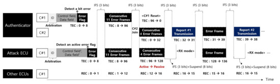
Figure 1.
Bus-off attack scenarios from a single-point adversary (IFS: Interframe space, Suspend: Suspend transmission, RX mode: Reception mode, Active: Error active state, Passive: Error passive state, C#1: Controller #1, C#2: Controller #2).
4.3. Countermeasures of MAuth-CAN
To protect from the above attacks, MAuth-CAN performs the authentication using dual-CAN controllers as shown in Figure 2.
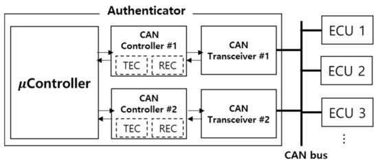
Figure 2.
New authenticator model with dual CAN controllers.
As the authenticator uses two CAN controllers, the reception and transmission queues are doubled. The controller has its own transmission error counter (TEC) and receive error counter (REC), thus dual-CAN controllers have two TECs and RECs for authentication. In particular, TEC is the decisive variable that determines to expel a CAN controller from CAN bus.
4.3.1. Countermeasure to Masquerade Attack
To avoid masquerade attacks, MAuth-CAN performs the authentication for every single message via CAN bus, as shown in Figure 3. When an ECU transmits a message upon CAN bus, every CAN controller takes the message into its reception queue but delays in reading it until the authentication for the message is done. A CAN controller keeps a new message in its reception queue for T B time units, as shown in Figure 3. The controller reads a new message when the TB expires (Pass scenario in Figure 3). If a message does not pass authentication, then a CAN authenticator creates and broadcasts an error report i.e., an authentication-fail report (AFR) and ECUs discard the message (Fail scenario in Figure 3). MAuth-CAN uses the duration of the length of 4 × Ttx for TB under the assumption that the transmission time is always greater than the authentication time. In this paper, we present the results of model checking for proving that the condition and the assumptions of MAuth-CAN authenticator are sufficient to protect masquerade attack to CAN system. The details regarding the AFR message is given in [21].
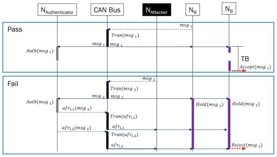
Figure 3.
Basics of MAuth-CAN.
4.3.2. Countermeasure to DoS and Bus-Off Attacks
Figure 4 shows a scenario that MAuth-CAN performs CAN message authentication under BoA, and consequently sends all AFR messages to ECUs when a message cannot pass the authentication.
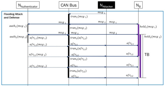
Figure 4.
MAuth-CAN resistant against flooding.
AFR Flooding
Every time an unauthenticated message comes in, the authenticator instantiates and broadcasts an AFR. Ideally, if the authenticator always dominates CAN bus over any nodes including the attacker, every ECU under masquerade attack must receive the AFR message within 4 × Ttx time units according to Figure 4. In order for the attacker not to be able to infer anything from AFR messages or reuse the previous AFR messages, the authenticator uses the reversed hash chain. An AFR message consists of two packets. Thus, the AFR message for the first adversary message can reach all nodes within 3 × Ttx time unit, but the AFR message for the second adversary message can be delayed by the first AFR message. For this reason, the waiting time of ECU for authentication needs to be 4 × Ttx time units.
BO Avoidance
Both authenticator and attacker attempt to dominate CAN bus at the same time if the highest priority CANID is open. If they send messages simultaneously with the same ID, the transmission error occurs and increases TEC of message senders i.e., the authenticator and the attacker, here. If either of authenticator or attacker’s TECs steps over a threshold of Active Error mode, it transits to Passive Error mode. When TEC goes over the limit of Passive Error mode, the ECU in Passive Error mode is enforced to leave CAN bus for a while.
To avoid this situation, the authenticator is equipped with two CAN controllers using two TECs of each CAN controllers. Consequently, both CAN controllers of the authentication cannot be enforced to enter into Passive Error mode at the same time.
MAuth-CAN is resilient to masquerade attacks if the authenticator leaves no missing message to verify at all. It is also sustainable under BoA because the attacker is disabled to send adversary messages faster than authenticator using two TECs in dual-CAN controllers.
4.4. Sufficient Conditions for MAuth-CAN Resiliency and Sustainability
CAN is resilient to masquerade attack if the authentication makes it to investigate every single message. Also, it is sustainable if the authentication is never disabled by BoA. MAuth-CAN achieves the above two goals by introducing a new authenticator equipped with two CAN controllers. In this paper, we show that MAuth-CAN achieves the above two goals with the following properties and prove them using model checking.
Theorem 1.
If MAuth-CAN authenticator uses a reception queue of size 2 for incoming new messages and the authentication time is always less than the message transmission time, it never fails to transmit AFR messages and the duration for ECUs to wait for AFR message needs no longer than 4 × Ttx.
Theorem 1 emphasizes on the size of the reception queue for the CAN controller of the authenticator and the relation between the authentication time and the transmission time. The size of the CAN controller’s reception queue is relevant to the resiliency of MAuth-CAN authenticator. The relation between the authentication time and the transmission time is relevant to the waiting time of ECUs for AFR messages.
Theorem 2.
MAuth-CAN authenticator is sustainable under BoA if it uses two CAN controllers.
The sustainability of MAuth-CAN in Theorem 2 means that MAuth-CAN is never enforced to be off from CAN bus. In order to prove Theorem 2, we focus on TEC of authenticator’s CAN controllers because TEC of the CAN controller goes over the threshold of Passive Error mode, then the CAN controller is enforced to leave CAN bus for a while. Thus, we will show that TEC of authenticator’s CAN controllers never goes over the threshold of Passive Error mode even if that of attacker’s CAN controller goes over the threshold. In next section, we will prove the above two theorems using model checking techniques.
5. Formal Analysis of MAuth-CAN
In this section, we present two formal models of CAN authentication in TA: An abstract CAN networking model and a detailed ECU model. The first model, the CAN networking model, captures the interlocking between three components: the authenticator, CAN bus, and ECUs. It focuses on verification of Theorem 1. The second model, the ECU model, details the behaviors of ECUs and bus at a bit-wise level so that the analysis can be done at a lower level. It focuses on verification of Theorem 2.
5.1. Model Checking Analysis of Theorem 1
To avoid the complexity of formal analysis, we abstract interaction between CAN components, as shown in Figure 5.
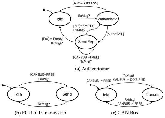
Figure 5.
CAN networking model. (a) This figure shows the state transitions of the authenticator in MAuth-CAN. (b) It shows the state transitions of an ECU in data transmission. (c) It shows the state transitions of the CAN bus for data transmission.
The model of CAN interaction comprises authenticator, attacker, and CAN bus. The attacker model has the same behavior as normal ECUs, but the authenticator in our model responds to the message from the attack by broadcasting AFR messages. We do not include the behavior of the CAN controller of CAN message receiver nodes in our model since the authenticator model has the same behavior as CAN message receiver and we focus on the resiliency of MAuth-CAN’s authentication that handles every attack message.
The authenticator model in Figure 5a waits for any message through CAN bus. When the authenticator reads a message (RxMsg) from CAN bus, the authenticator in Figure 5a transits into the location Authenticate for processing authentication. If the message passes the authentication, it returns to Idle state. Otherwise, it joins SendRep state. Then, it sends the AFR message for the unauthenticated message when CAN bus is available (CANBUS = FREE). The authenticator keeps any message in its reception queue (EnQ) when it is in authentication. If the queue is empty, the authenticator returns to the initial location Idle. Otherwise, it returns to Authenticate and performs authentication for another incoming message again.
The CAN controller model of an attacker in Figure 5b is simpler than the authenticator. If the CAN controller has a message to send and CAN bus is available, it just sends it through CAN bus. Notice that it returns to the initial location when the transmission of the message is acknowledged by CAN bus through the event RxMsg.
The CAN bus model in Figure 5c controls the permission for a CAN controller to access CAN bus. Initially, it allows any controller to use CAN bus by setting CANBUS:=FREE. If the CAN bus receives a message via TxMsg, it locks the key by setting CANBUS:=OCCUPIED, prohibits any node from using CAN bus, moves to Transmit location, and notifies the transmitting of a message. Finally, the CAN bus returns to the initial location Idle with unlocking the key with setting CANBUS:=FREE.
Based on the CAN networking model in Figure 5, Figure 6 captures CAN behavior models in TA. It also comprises three models: Authenticator, ECU and CAN bus. Four TA processes are instantiated for simulation and verification: Two authenticator processes from the authenticator model, one CAN attacker process from the ECU model, and one CAN bus process from the CAN bus.
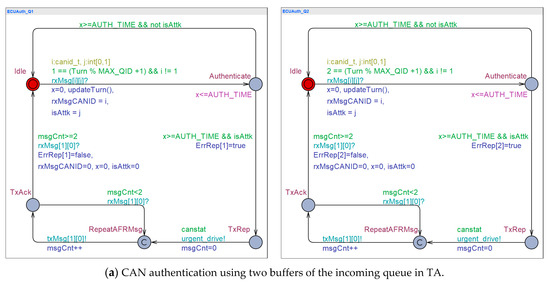
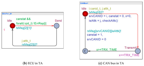
Figure 6.
Simulation of CAN networking in TA. (a) This figure shows two UPPAAL processes of message authenticator that individually process authentication of incoming message. (b) This figure shows an UPPAAL process of an ECU that continuously sends messages, simulating message flooding attack. (c) This figure shows an UPPAAL process of a CAN bus that simulates the message transmission in the synchronization with the sender ECU and the receiver ECU.
As shown in Figure 6a, two authenticator processes are instantiated from the authenticator model to capture message queuing behavior using the reception queue of size 2. It particularly highlights the concurrent behavior of the CAN controller’s authentication, reception, and message transmission using the reception queue of size 2. When a new message arrives, authenticator’s CAN controller checks the message and sends AFR messages for unauthenticated messages. While the authenticator is sending AFR, it can simultaneously receive another new message. It is because the reception queue and sending queue of a CAN controller are separate. However, only one of them can process authentication at the same time. The authenticator processes, ECUAuth_Q1 and ECUAuth_Q2, in Figure 6a have an invariant over Authenticate location, which limits the authentication time to a specific time bound AUTH_TIME. The authenticator process leaves Authenticate location after AUTH_TIME expires and transits to TxRep location so as to send one of AFR messages. In this interaction model, canstat represents the status of CAN bus. The authenticator process can send the AFR message through CAN bus when no node occupies CAN bus, then canstat value of CANBus1 is set to true (1). When TA authenticator enters RepeatAFRMsg location, it broadcasts two consecutive packets for one AFR message.
The ECU process in ECUTx1_Q1 of Figure 6b may send any attack message (txMsg[canid][attkid]) at any time if CAN bus is available. If the reception of the attack message is acknowledged by the authenticator i.e., rxMsg[canid][attkid] is received, it may send another message.
The CAN bus in CANBus1 of Figure 6c manages the permission for use of CAN bus using canstat. If the CAN bus process receives a message from an ECU and the authenticator, it sets canstat to false (0). Then, any CAN controller cannot occupy CAN bus. The transmission of messages is captured with the clock x and the invariant TRX_TIME over Transmit location. The CAN bus process stays over Transmit location for TRX_TIME time units, and then it leaves Transmit location with synchronizing the channel rxMsg and setting canstat to true (1). Particularly, The CAN bus model is designed to count the number of attack messages using the function checkAttk(). The number is denoted by AttMsgCnt. AttMsgCnt keeps increasing, meaning that the authenticator fails to check the attack message. If AttMsgCnt keeps below a specific number, particularly the reception queue size of the authenticator, it means that the authenticator succeeds in authenticating every attack message.
MAuth-CAN authenticator must not miss any message without verification, meaning that no ECU should not read unauthenticated message. All CAN controllers on ECUs temporarily store any incoming message in the reception queue during authentication. They postpone reading it until a predefined authentication time ends. However, when the AFR message arrives within the predefined authentication time, the CAN controller regards that the message in the reception queue fails the authentication and discards it. For the reasons, it is crucial to characterize the AFR waiting time TB i.e., the duration that an ECU waits for AFR message. Also, the CAN authenticator is capable of verifying consecutive adversary messages and transmit AFR messages within a predefined authentication time so as to protect every ECU from adversary messages. In terms of the authenticator, we prove the following lemma in order to characterize the CAN controller of the authenticator that can protect adversary messages in any forms:
Lemma 1.
If the CAN controller of the authenticator is given the reception queue of size 2 and the transmission time is less than the authentication time, it can always verify every new message and every ECU does not miss AFR.
In order to prove Lamma 1, we model-check the CAN controller model of the authenticator and checks the number of delayed AFR messages in the transmission queue. If the variable AttkMsgCnt is not larger than the size of the reception queue, we can say that the authenticator has no remaining AFR to send. The following two CTL properties are checked by UPPAAL MC and the verification results are also shown in Table 3:
CTL-Property-1: A[] not deadlock
CTL-Property-2: A[] AttkMsgCnt ≤ IQSizeAUTH
Table 3.
Setting of the model checking for Lemma 1 and model-checking results.
CTL-Property-1 specifies that the system is put into no deadlock where no progress is made. CTL-Property-2 states that AttkMsgCnt is not larger than the maximum reception queue size of authenticator’s CAN controller.
To prove Lemma 1, we have six different configurations in Table 3, where the maximum reception queue size of the authenticator, the authentication time, and transmission time are varied. The maximum reception queue size is either of one or two. The transmission time and the authentication time are also varied in such a way that Tauth~Ttx where ~= {<, =, >}.
In Table 3, Tauth and Ttx denote the authentication processing time and the transmission time, respectively. The results show that CAN authentication needs no more than two queues if the authentication time is less than the transmission time, so that no message is missed without verification.
To validate our models, we simulate the model using statistical model checking technique and the following query:
Sim-Property-1: simulate [≤100;1] CANBus1.srvCANID
This query states which CANID preempts CAN bus over time.
Figure 7 shows a simulation of CAN authentication with different number of CAN controller. The x-axis represents the time and the y-axis represents the identifier of a CAN controller which makes it to transmit a message. Thus, Figure 7 shows which CAN controller makes it to transmit messages over time. The attacker’s CANID is 2 and the authenticator’s is 1.
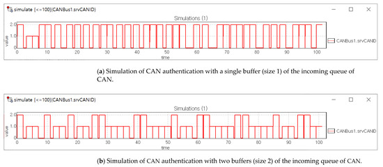
Figure 7.
Simulation of CAN authentication nodes. (a) This figure shows that the attack messages are overwhelming CAN bus by message flooding attack, and blocking all AFR messages from the authenticator. (b) This figure shows that two consecutive AFR messages for one attack message are transmitted on CAN bus without failure and the attack message cannot dominate CAN Bus.
Figure 7a shows the case where the authenticator’s CAN controller uses a single buffer of a reception queue so it cannot handle no more than one message. The first two messages are adversary messages sent by the attacker. The third and fourth messages are the AFR messages sent by the authenticator after addressing the first adversary message. Note that authenticator’s CAN controller succeeds in sending the AFR messages for the first adversary message, but not the rest of the adversary messages.
Meanwhile, the plot in Figure 7b shows different behavior of CAN authentication when authenticator’s CAN controller 2 size of the reception queue. In Figure 7b, the first two transmissions are made by the attacker. The second adversary message transmission is possible while the authenticator is checking the first adversary message. However, the 4 transmissions following the first two adversary messages are made for AFR messages by the authenticator. That is consistent with Figure 4: Two attack messages can be consecutively transmitted over CAN bus, but AFR messages follow those attack messages. In following, all AFR messages are successfully sent following every attack message. No AFR message is delayed by adversary message, then no adversary message is adopted by ECUs due to AFR messages.
In order to compute the minimum TB, we present Lemma 2:
Lemma 2.
If the CAN authenticator makes it to address all consecutive attack messages, TB is not necessarily longer than 4 × Ttx.
In our model, for a given authentication time, denoted by Tauth, and transmission time, denoted by Ttx, we can measure the maximum communication delay, using the clocks ECUAuth_Q1.x and ECUAuth_Q2.x on the locations ECUAuth_Q1.TxAck and ECUAuth_Q2.TxAck. For given Tauth = 1 and Ttx = 2, we check the worst-case time for the AFR message to arrive all ECUs. We use the following queries:
CTL-Property-3: sup{ECUAuth_Q1.TxAck}: ECUAuth_Q1.x
CTL-Property-4: sup{ECUAuth_Q2.TxAck}: ECUAuth_Q2.x
“sup{expr}: list” in UPPAAL MC returns the maximum value of variables in “list”. That is, the expression in list is evaluated only on the states that satisfy expr (a state predicate) that acts like an observation.
Model checking shows that the worst-case response time of the AFR is always 8 (4 × Ttx). That is consistent with the illustration in Figure 4, thus we can conclude that 4 × Ttx is the minimum TB.
In the results of model-checking for CTL-Property-1, 2, 3, and 4, we prove Lemma 1 and Lemma 2. Consequently, Theorem 1 is proved by the proofs of Lemma 1 and Lemma 2.
In this section, we show that MAuth-CAN is resilient to masquerade attack using consecutive adversary messages if the authenticator reads incoming message using 2 size of reception queue and the authentication time is less than the message transmission time. In particular, it is shown that the consecutive two messages of AFR sent by the authenticator can prevent the flooding of adversary messages by preempting CAN bus. However, it is true only if the AFR messages is successfully transmitted to other nodes.
In next section, we will show that MAuth-CAN is sustainable to BoA even if CAN priority is not secure and attacker can utilize the highest priority of CAN.
5.2. Model Checking Analysis of Theorem 2
Recall the scenario that BoA enforces the CAN controller of the authenticator to leave CAN bus for a while. When the authenticator tries to transmit AFR messages, the attacker causes transmission error. The attacker with the same priority of CAN bus begins the attack message transmission at the same time when the authenticator begins message transmission. Then, two messages conflicts, resulting in transmission error. The repeated transmission errors accumulate up to a specific count, then CAN system gets rid of the attacker and the authenticator from CAN bus for a while. The CAN authentication should be designed to sustainable against this BoA.
In order to capture such a complicated situation, we present more concrete and detailed model of the CAN controller and bus in TA. Our CAN controller model in TA captures a detailed behavior of the CAN controller based on the CAN protocol in Figure 8. We capture CAN controller’s behavior in a bit-wise level as if a simple protocol is captured by a TA as shown in Figure 9. In Figure 9, a frame consists of a specific number of bits and TA captures the behavior of such a frame with the same series of time units. Here, we do not consider the semantics of bits and focus on a bit-wise timing behavior of the protocol.
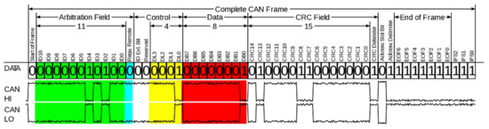
Figure 8.
CAN-Frame in base format in bit levels [30].
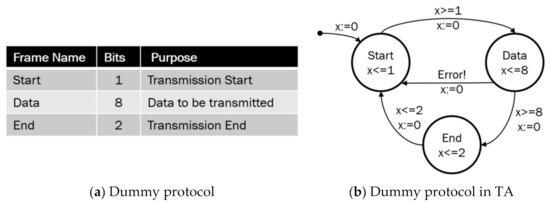
Figure 9.
Modeling a dummy protocol into TA. (a) This figure gives an example of a simple protocol in packet frames. (b) This figure captures the simple protocol into a TA model in a bit-wise level.
If a protocol evolves from one frame to another frame, TA captures the frames transits from one location and to another location. Basically, a frame is captured by a location in our TA model, where our TA model stays for the same time units as the number of bits of a frame. For example, the Start frame using 1 bit in Figure 9 is captured by the Start location where TA stays for the same number of time units as 1 bit. A specific event occurring on a frame can be captured by an event causing a transition leaving off the location representing the frame. For example, if a Data frame in Figure 9 encounters an error and needs re-transmission, then TA captures it by a transition returning from Data location to Start location.
Figure 10 and Figure 11 shows TA models of CAN bus and controller in the MAC level of the data link layer. The CAN controller has three modes: Receiving mode, transmission mode, and error handling mode. The receiving mode consists of receiving (Rxing) and error handing locations (RxErrRep, RxErrStuffing, RxErrDelimite). The transmission mode is composed of multiple transmissions of different frames, as shown in Figure 11. When a CAN controller needs data transmission, the CAN controller model at the location Rxing in Figure 10 checks if CAN bus is available by checking the condition variable canstat. The SOF frame of Figure 8 is modeled by the invariant x ≤ SOF over the location StartTrans and the guard x==SOF on the transition leaving StartTrans in Figure 11. Note that the Arbitration Field frame needs an interaction of CAN controller with the CAN bus for CAN bus arbitration and such a scheduling responsibility is placed upon the CAN bus, so the Arbitration Field frame is modeled on the location CANArbitration in CAN bus model of Figure 10. The last 1 bit of Arbitration frame field and the first 2 bits of Control field are abstracted together by the location DestControl. When more than one CAN controller attempt to make any frame transmissions simultaneously, it may lead to a transmission error status of CAN controller and bus. The transmission error is captured by the transition leaving the location Txing of Figure 11 having no guard. The transition may be taken non-deterministically to leave the location Txing, and that implies that our CAN controller model of TA can go to a transmission error (handling) status at any time. When a transmission error occurs, the CAN controller is put into one of Active Error model, Passive Error mode, or Reset. When a transmission error happens, the CAN controller goes to at Active Error mode and an Active Error frame will be transmitted on the bus if TEC (Transmission Error Counter) is lesser than 128. If TEC is greater than 127 and lesser than 255, then the CAN controller is led to Passive Error mode and a Passive Error frame will be transmitted on the bus.
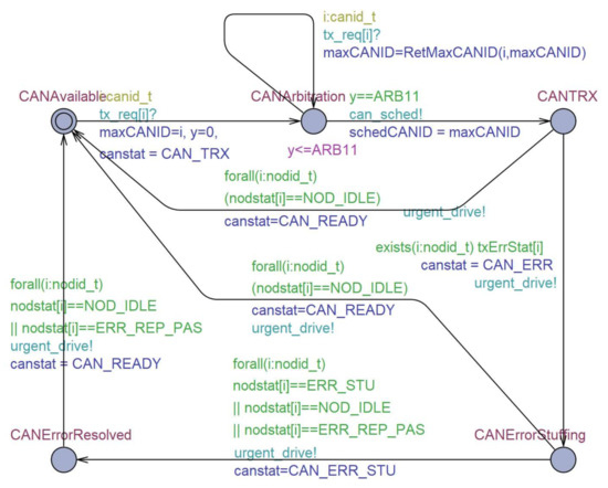
Figure 10.
CAN bus model in TA.
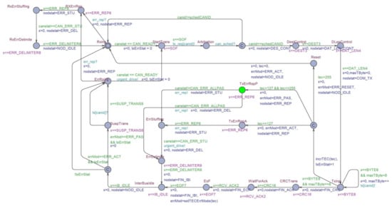
Figure 11.
A CAN controller model in TA.
The CAN controller in Passive Error mode is given a penalty in such a way that it is more delayed to make transmission than the CAN controller in Active Error or Normal modes. The situation is captured by our CAN controller model of TA where the CAN controller in Passive Error mode should stay over SuspTrans location for 8 time-units. When TEC of a CAN controller is greater than 255, then the controller enters Bus Off state, where no frames cannot be transmitted by the controller [30]. We capture the BO situation with Reset location in Figure 11, where the CAN controller stays for a while without being able to send any message.
Now, we present the formal verification results of model checking for MAuth-CAN under BoA. In order to prove Theorem 1 that the CAN controller in charge of the authentication is sustainable to BoA, we need to verify if our dual-CAN controllers can never be put into Passive Error mode when the attacker crafts continually to cause transmission errors. We introduce to Lemma 3 as follows:
Lemma 3.
Dual-CAN controllers of MAuth-CAN authentication is never put into Passive Error mode together at the same time when the attacker is in Passive Error mode.
We prove Lemma 3 by model checking as follows: In order to reduce the state space of our models, the TA authenticator model and the TA at-tacker model in Figure 12 and Figure 13 are mutated from the CAN controller model of Figure 11 so that they terminate analysis when one of them goes into Passive Error mode. That is, when either of the authenticator controller or the attack controller goes to Passive Error mode first, then the analysis is over. We verify that both dual-CAN controllers for authentication never go to Passive Error mode at the same time. In this way, our model checking using the mutated CAN controller models can be less suffering state-explosion issue. We use the following queries to prove Lemma 3:
CTL-Property-5: A[] not deadlock
CTL-Property-6: A[] CANContAttk3.errMod==ERR_PAS imply (CANContAuth1.errMod != ERR_PAS or CANContAuth2.errMod != ERR_PAS)
CTL-Property-7: A[] (CANContAuth1.errMod! = ERR_PAS or CANContAuth2.errMod! = ERR_PAS)
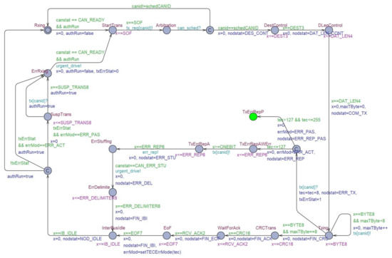
Figure 12.
An ECU controller model of the authenticator in TA.
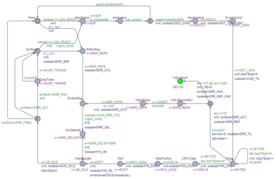
Figure 13.
An ECU controller model of the attacker in TA.
CTL-Property-5 specifies that the system model should never be in deadlock status in which every process stops running. We use it to check if our TA model is valid to check using model checking. CTL-Property-6 specifies that the error mode (errMod) of both authenticators (CANContAuth1 and CANContAuth2) would never be in Passive Error mode (ERR_PAS) together at the same time when the error mode (errMod) of the attacker (CANContAtt3) happens to be in Passive Error mode (ERR_PAS). Similarly, CTL-Property-7 is used to check if they can fall into Passive Error mode.
Figure 14 shows that the properties above are met by our model, implying that Lemma 3 is proved by the model checking of the CTL properties. By proving Lemma 3, we conclude that Theorem 1 is proved and that our authentication using dual-CAN controllers is resilient to BoA even when the attacker can exploit the highest priority of CAN controller.
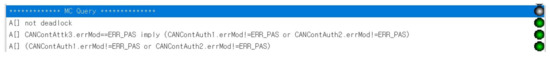
Figure 14.
Model checking results for MAuth-CAN’s resiliency to BoA.
Our model checking environment is as follows:
- Processor: Intel Core i7 CPU, 1.80GHz, 2.30GHz
- RAM: 16.0GB
- OS: Windows 10-64Bits
6. Implementation and Experiments
In this section, the implementation and experimental results of MAuth-CAN are provided to check whether Theorem 1 and 2 proved in the formal analysis are applicable to the CAN testbed considering real CAN traffic with message authentication. In the experiment of MAuth-CAN, we adopt the BLAKE2S algorithm with keyed mode for implementation of message authentication code, which is used to generate authentication tags for CAN messages and report messages. BLAKE2S is a cryptographic hash function which is faster than keccak (SHA3) in software implementations. The security proof of BLAKE2S with keyed mode is referred to [31]. We tested the implemented source codes on the Raspberry Pi 3 Model B and Arduino Zero that are assumed to be the authenticator and the normal ECUs, respectively.
6.1. Message Authentication Time
When an ECU transmits a CAN message, it always generates a message authentication tag (i.e., a MAC value). The CAN message then is verified by the authenticator and a report message (an AFR message) is generated if there is a verification failure. The normal ECUs verify an AFR message to see if it is transmitted by the authenticator only when they receive it. We tested each operation one hundred times, and the average the computation time and the corresponding standard deviation for individual cryptographic operations are presented in Table 4.
Table 4.
Individual operations of MAuth-CAN (µs).
6.2. Reception Time of an AFR Message
We evaluate the reception time of an AFR message under the following two attacks: message flooding attack and BoA.
6.2.1. Reception Time of an AFR Message under Message Flooding Attacks
As shown in Table 4, the sum of and is approximately 56.4 µs and less than the transmission time of an AFR message, i.e., 444 µs = = (111 bits is size of a CAN data frame with an 8 byte data field if the bit-stuffing rule of the CAN standard is ignored). Since the time to authenticate a CAN message and to generate a report message is less than the transmission time of the report message, the authenticator can authenticate all CAN messages without increasing its own message queue. Thus, every report message for an invalid CAN message can be transmitted successfully within a bounded time, which is the length of 4 × the transmission time as described in Theorem 1. According to our implementation result, the worst time of report reception under the flooding attacks is approximately 1012 µs, as shown in Figure 15a.
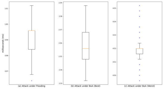
Figure 15.
The reception time of an AFR message under attacks. (a) This figure shows the AFR reception time under message flooding. Note that the maximum time of AFRs is 1012 µs. (b) This figure shows the ARF reception time under BoA where the malicious ECU creates the bit-error at the FIRST bit position in the AFR message. (c) This figure shows the ARF reception time under BoA where the malicious ECU creates the bit-error at the LAST bit position in the AFR message.
The reception time shown in Figure 15a is slightly larger than 888 µs = = , which is the theoretical transmission time of four CAN packets. The reason is that this experimental time is affected by the bit stuffing rule for synchronization of CAN bus and the time measurement error originating from Arduino UNO. In order to maintain synchronization of CAN bus, a bit stuffing rule is defined in the CAN standard. In this rule, a bit of opposite value is inserted after every five consecutive bits of the same value. For example, if six consecutive dominant bits, , are transmitted by the host controller of an ECU, the CAN controller of the ECU adds one recessive bit after every five consecutive dominant bits . This additional bit is automatically removed by the CAN controllers of receiver ECUs.
6.2.2. Reception Time of an AFR Message under BoA
BoA on the authenticator causes the transmission delay of an AFR message. In general, the continuous BoA can permanently interfere with the communication from an ECU. However, since the authenticator of MAuth-CAN has two CAN controllers, it is possible for the authenticator to put a malicious ECU that performs the BoA into Passive Error mode which allows the transmission of an AFR message from the authenticator.
The time it takes for the malicious node performing BoA to become the error passive state varies depending on the attack bit position for the BoA (i.e., a bit-error position in the data field of an AFR message). If the malicious node performing BoA creates the first bit-error at the first bit position in the data field of an AFR message, the reception time of an AFR message is approximately 2355 ms as shown in Figure 15b. In other hands, to maximize the transmission delay of an AFR message by the BoA, the malicious node performing BoA can create a bit-error at the last bit position (i.e., 64th bit position in the data field) of an AFR message. In this the worst case, the reception time of an AFR message is approximately 4495 ms as shown in Figure 15c.
Through this experiment, we show Theorem 2 by validating that Passive Error mode of the malicious node performing BoA on the authenticator allows the authenticator with dual CAN-controllers to transmit an AFR message within the bounded time and the worst case time is 4495 ms.
7. Conclusions
CAN is the most common in-vehicle network system. The latest automobiles developed recently are equipped with numerous ECUs. The ECU over CAN bus can be a victim of security attacks leading to critical risks of vehicle safety. In particular, in case that the infotainment system of unwarranted third party vendor and driving control systems share CAN bus, the security risk is dramatically escalated.
MAuth-CAN is a centralized authentication mechanism for CAN. In MAuth-CAN, the response timing is critical for the properties since a timeout works for the indication that a message passes authentication and ECUs accept a new message stored in its temporary queue when the timeout expires. MAuth-CAN utilizes two CAN controllers for fault-tolerance mechanism so that it continues its functionality under message flooding and bus-off attacks.
This paper presents the formal proofs of resiliency and sustainability of MAuth-CAN authentication against message flooding and bus-off attacks where timing is critical to maintain such properties. Also, this paper shows how model checking, a formal verification technique, works for safety and security certificates of in-vehicle network. In this paper, we present a novel CAN model in a formal model, which captures CAN’s timing behavior in MAC level of the data-link layer and can thus be used for verification of safety properties of other CAN applications. Using this CAN model, we perform formal verification for the sufficient conditions of those properties of MAuth-CAN.
As conclusions, we show that MAuth-CAN authenticator is sufficiently resilient and sustainable against those two kinds of attacks if MAuth-CAN authenticator can handle two consecutive attack messages, the authentication time is less than the message transmission time, and MAuth-CAN authenticator uses two CAN controllers. Also, we conclude that 4 × Ttx is the minimum and sufficient length of the timeout for ECUs to open incoming messages that have passed MAuth-CAN authentication. The experiment results from the implementation of MAuth-CAN are shown to be consistent with that propositions and conditions we have shown in this paper.
Author Contributions
Conceptualization, J.H.K., H.J.J. and I.L.; methodology, J.H.K.; validation, I.L. and H.J.J.; writing—original draft preparation, J.H.K. and H.J.J.; writing—review and editing, I.L.; supervision, I.L.; project administration, I.L.; funding acquisition, I.L., J.H.K., H.J.J. and All authors have read and agreed to the published version of the manuscript.
Funding
This work was supported in part by NRF-2020R1A2C1014855, NRF-2018R1C1B5086261, and ONR N00014-17-1-2012 and ONR N00014-20-1-2744.
Institutional Review Board Statement
Not applicable.
Informed Consent Statement
Not applicable.
Data Availability Statement
Data sharing not applicable.
Conflicts of Interest
The authors declare no conflict of interest.
References
- Koscher, K.; Czeskis, A.; Roesner, F.; Patel, S.; Kohno, T.; Checkoway, S.; McCoy, D.; Kantor, B.; Anderson, D.; Shacham, H.; et al. Experimental Security Analysis of a Modern Automobile. In Proceedings of the 2010 IEEE Symposium on Security and Privacy, Berkeley, CA, USA, 22–25 May 2011; pp. 447–462. [Google Scholar] [CrossRef]
- Checkoway, S.; McCoy, D.; Kantor, B.; Anderson, D.; Shacham, H.; Savage, S.; Koscher, K.; Czeskis, A.; Roesner, F.; Kohno, T. Comprehensive Experimental Analyses of Automotive Attack Surfaces. In Proceedings of the 20th USENIX Conference on Security; SEC’11; USENIX Association: Berkeley, CA, USA, 2011; p. 6. [Google Scholar]
- Foster, I.; Prudhomme, A.; Koscher, K.; Savage, S. Fast and Vulnerable: A Story of Telematic Failures. In Proceedings of the 9th USENIX Workshop on Offensive Technologies (WOOT 15), Washington, DC, USA, 10–11 August 2015. [Google Scholar]
- Miller, C.; Valasek, C. Remote Exploition of an Unaltered Passenger Vehicle. Black Hat USA 2015, 2015, 91. [Google Scholar]
- Woo, S.; Jo, H.; Lee, D. A Practical Wireless Attack on the Connected Car and Security Protocol for In-Vehicle CAN. IEEE Intell. Transp. Syst. 2015, 16, 993–1006. [Google Scholar] [CrossRef]
- Jo, H.J.; Choi, W.; Na, S.Y.; Woo, S.; Lee, D.H. Vulnerabilities of Android OS-Based Telematics System. Wirel. Pers. Commun. 2017, 92, 1511–1530. [Google Scholar] [CrossRef]
- Taylor, A.; Japkowicz, N.; Leblanc, S. Frequency-based anomaly detection for the automotive CAN bus. In Proceedings of the 2015 World Congress on Industrial Control Systems Security (WCICSS), London, UK, 14–16 December 2015; pp. 45–49. [Google Scholar] [CrossRef]
- Song, H.M.; Kim, H.R.; Kim, H.K. Intrusion detection system based on the analysis of time intervals of CAN messages for in-vehicle network. In Proceedings of the 2016 IEEE International Conference on Information Networking (ICOIN), Kota Kinabalu, Malaysia, 13–15 January 2016; pp. 63–68. [Google Scholar] [CrossRef]
- Tomlinson, A.; Bryans, J.; Shaikh, S.A.; Kalutarage, H.K. Detection of Automotive CAN Cyber-Attacks by Identifying Packet Timing Anomalies in Time Windows. In Proceedings of the 2018 48th Annual IEEE/IFIP International Conference on Dependable Systems and Networks Workshops (DSN-W), Luxembourg, 25–28 June 2018; pp. 231–238. [Google Scholar] [CrossRef]
- Marchetti, M.; Stabili, D. Anomaly detection of CAN bus messages through analysis of ID sequences. In Proceedings of the 2017 IEEE Intelligent Vehicles Symposium (IV), Los Angeles, CA, USA, 11–14 June 2017; pp. 1577–1583. [Google Scholar] [CrossRef]
- Kang, M.J.; Kang, J.W. Intrusion Detection System Using Deep Neural Network for In-Vehicle Network Security. PLoS ONE 2016, 11, 1–17. [Google Scholar] [CrossRef] [PubMed]
- Song, H.M.; Woo, J.; Kim, H.K. In-vehicle network intrusion detection using deep convolutional neural network. Veh. Commun. 2020, 21, 1–13. [Google Scholar] [CrossRef]
- Cho, K.T.; Shin, K.G. Fingerprinting Electronic Control Units for Vehicle Intrusion Detection. In Proceedings of the 25th USENIX Security Symposium (USENIX Security 16), Austin, TX, USA, 10–12 August 2016; pp. 911–927. [Google Scholar]
- Hartkopp, O.; Reuber, C.; Schilling, R. MaCAN—Message Authenticated CAN. In Proceedings of the 10th International Conference on Embedded Security in Cars (Escar Euroupe 2012), Berlin, Germany, 28–29 November 2012. [Google Scholar]
- Kang, K.D.; Baek, Y.; Lee, S.; Son, S.H. An Attack-Resilient Source Authentication Protocol in Controller Area Network. In Proceedings of the 2017 ACM/IEEE Symposium on Architectures for Networking and Communications Systems (ANCS), Beijing, China, 18–19 May 2017; pp. 109–118. [Google Scholar] [CrossRef]
- Nürnberger, S.; Rossow, C. vatiCAN—Vetted, Authenticated CAN Bus. In Proceedings of the 18th International Conference on Cryptographic Hardware and Embedded Systems (CHES 2016), Santa Barbara, CA, USA, 17–19 August 2016; Springer: Berlin/Heidelberg, Germany, 2016; pp. 106–124. [Google Scholar] [CrossRef]
- Radu, A.I.; Garcia, F.D. LeiA: A Lightweight Authentication Protocol for CAN. In Proceedings of the 21st European Symposium on Research in Computer Security (ESORICS 2016), Heraklion, Greece, 28–30 September 2016; Springer: Berlin/Heidelberg, Germany, 2016. [Google Scholar]
- Kurachi, R.; Matsubara, Y.; Takada, H.; Adachi, N.; Miyashita, Y.; Horihata, S. CaCAN—Centralized Authentication System in CAN (Controller Area Network). In Proceedings of the 12th International Conference on Embedded Security in Cars (escar Euroupe 2014), Hamburg, Germany, 18–19 November 2014. [Google Scholar]
- Groza, B.; Murvay, S.; Herrewege, A.V.; Verbauwhede, I. LiBrA-CAN: Lightweight Broadcast Authentication for Controller Area Networks. ACM Trans. Embed. Comput. Syst. 2017, 16, 1–28. [Google Scholar] [CrossRef]
- Wang, E.; Xu, W.; Sastry, S.; Liu, S.; Zeng, K. Hardware Module-based Message Authentication in Intra-vehicle Networks. In Proceedings of the 8th International Conference on Cyber-Physical Systems, ICCPS ’17, Pittsburgh, PA, USA, 18–20 April 2017; ACM: New York, NY, USA, 2017; pp. 207–216. [Google Scholar] [CrossRef]
- Jo, H.J.; Kim, J.H.; Choi, H.; Choi, W.; Lee, D.H.; Lee, I. MAuth-CAN: Masquerade-Attack-Proof Authentication for In-Vehicle Networks. IEEE Trans. Veh. Technol. 2020, 69, 2204–2218. [Google Scholar] [CrossRef]
- Sagong, S.U.; Ying, X.; Clark, A.; Bushnell, L.; Poovendran, R. Cloaking the Clock: Emulating Clock Skew in Controller Area Networks. In Proceedings of the 9th ACM/IEEE International Conference on Cyber-Physical Systems, ICCPS ’18, Porto, Portugal, 11–13 April 2018; IEEE Press: Piscataway, NJ, USA, 2018; pp. 32–42. [Google Scholar] [CrossRef]
- Testa, A.C.M.; Coronato, A. Heuristic strategies for assessing wireless sensor network resiliency: An event-based formal approach. J. Heuristics 2015, 21, 145–175. [Google Scholar] [CrossRef]
- Bengtsson, J.; Yi, W. Timed automata: Semantics, algorithms and tools. Lect. Notes Comput. Sci. 2004, 3098, 87–124. [Google Scholar]
- Behrmann, G.; David, A.; Larsen, K. A Tutorial on Uppaal. In Formal Methods for the Design of Real-Time Systems; Springer: Berlin/Heidelberg, Germany, 2004; pp. 33–35. [Google Scholar]
- Alur, R.; Feder, T.; Henzinger, T.A. The benefits of relaxing punctuality. JACM 1996, 43, 116–146. [Google Scholar] [CrossRef]
- David, A.; Larsen, K.G.; Legay, A.; Mikučionis, M.; Poulsen, D.B. Uppaal SMC tutorial. Int. J. Softw. Tools Technol. Transf. 2015, 17, 397–415. [Google Scholar] [CrossRef]
- Eldefrawy, K.; Francillon, A.; Perito, D.; Tsudik, G. SMART: Secure and Minimal Architecture for (Establishing a Dynamic) Root of Trust. In Proceedings of the 19th Annual Network and Distributed System Security Symposium (NDSS 2012), San Diego, CA, USA, 5–8 February 2012. [Google Scholar]
- Koeberl, P.; Schulz, S.; Sadeghi, A.R.; Varadharajan, V. TrustLite: A Security Architecture for Tiny Embedded Devices. In Proceedings of the Ninth European Conference on Computer Systems, EuroSys ’14, Graz, Austria, 7–13 May 2006; ACM: New York, NY, USA, 2014; pp. 1–14. [Google Scholar] [CrossRef]
- Wikipedia. CAN Bus. Available online: https://en.wikipedia.org/wiki/CAN_bus (accessed on 20 January 2021).
- Luykx, A.; Mennink, B.; Neves, S. Security Analysis of BLAKE2’s Modes of Operation. IACR Trans. Symmetric Cryptol. 2016, 2016, 158–176. [Google Scholar] [CrossRef]
Publisher’s Note: MDPI stays neutral with regard to jurisdictional claims in published maps and institutional affiliations. |
© 2021 by the authors. Licensee MDPI, Basel, Switzerland. This article is an open access article distributed under the terms and conditions of the Creative Commons Attribution (CC BY) license (http://creativecommons.org/licenses/by/4.0/).