
Collaborative Workplace Design: A Knowledge-Based Approach to Promote Human–Robot Collaboration and Multi-Objective Layout Optimization

 ,
,  , , ,
, , ,  ,
, 
Abstract
1. Introduction
Outline of the Paper
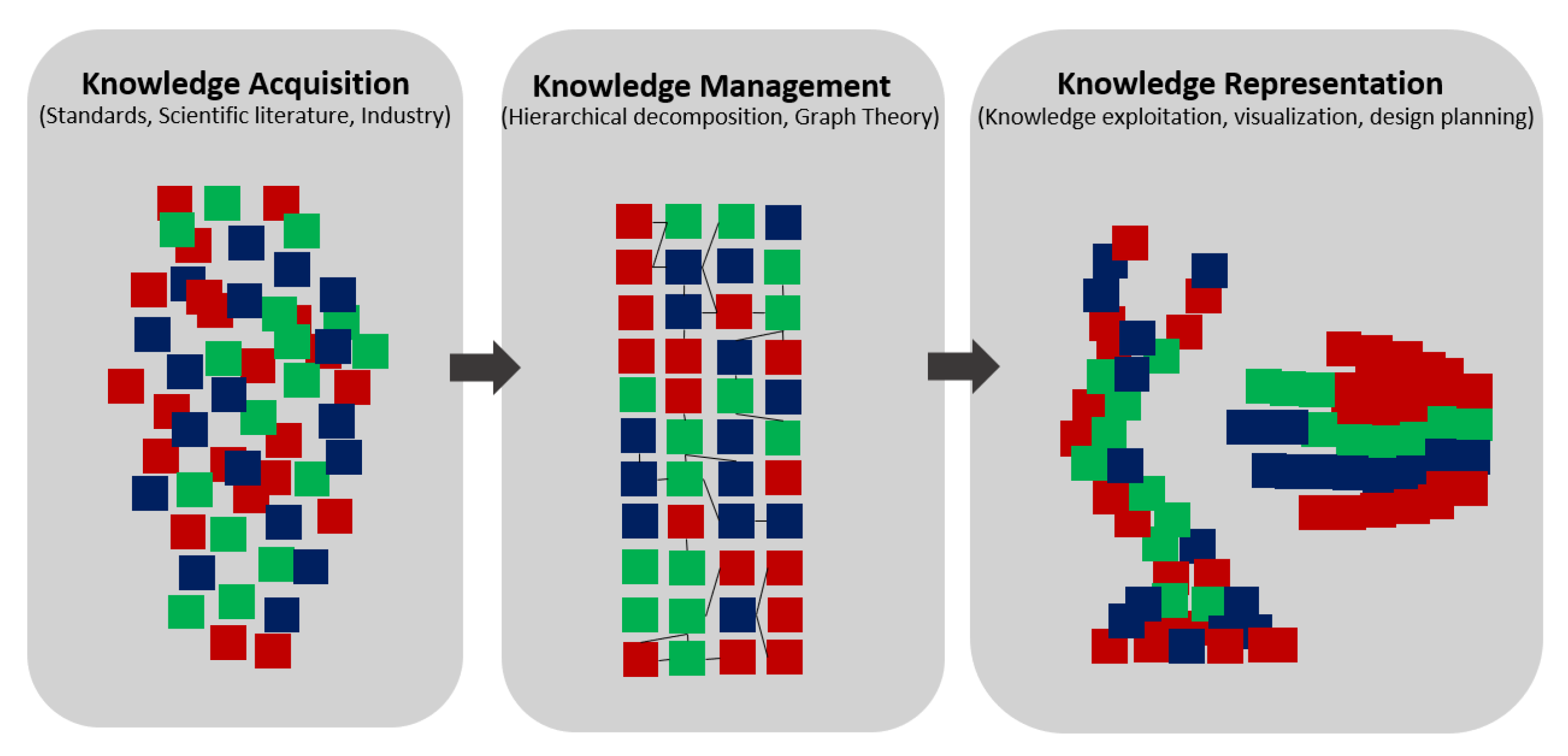
- 1.
- Knowledge Acquisition takes care of the exploration of the whole HRC domain. Information coming from academia, regulatory frameworks, and industry are selected and studied to identify who has influence on the collaborative workplace implementation.
- 2.
- Knowledge Management deals with the organizing of the collected knowledge in a structured and hierarchical form. The dense network of emerged information is managed using the graph theory.
- 3.
- Knowledge Representation allows us to identify what to focus on during the layout designing process. These can be summarized in the macro phase named KBA, which led to the following steps:
- 4.
- Definition of the modeling paradigm containing the main elements that affect the design of the HRC workplace layout. Their features, the constraints to which they are subjected, and the design parameters are collected and classified according to their influence on the layout designing.
- 5.
- Proposal of a structured approach, based on the paradigm, which addresses the problem of the HRC workplace layout designing according to an optimization criterion bound to compliance with the reference standards.
- 6.
- Application of the proposed approach in the designing of the layout of a collaborative workplace for quality inspection of welded parts in the automotive industry.
2. State of Art
3. A Knowledge-Based Approach for the Investigation of Collaborative Workplaces
3.1. Knowledge Acquisition
- Type A standards: basic safety standards and requirements that apply to machinery.
- Type B standards: generic safety standards divided in two sub-categories.
- -
- B1 standards concern specific safety aspects.
- -
- B2 standards concern safeguard measures, interlocking devices, and optical or pressure sensors.
- Type C standards: safety requirements for specific machinery.
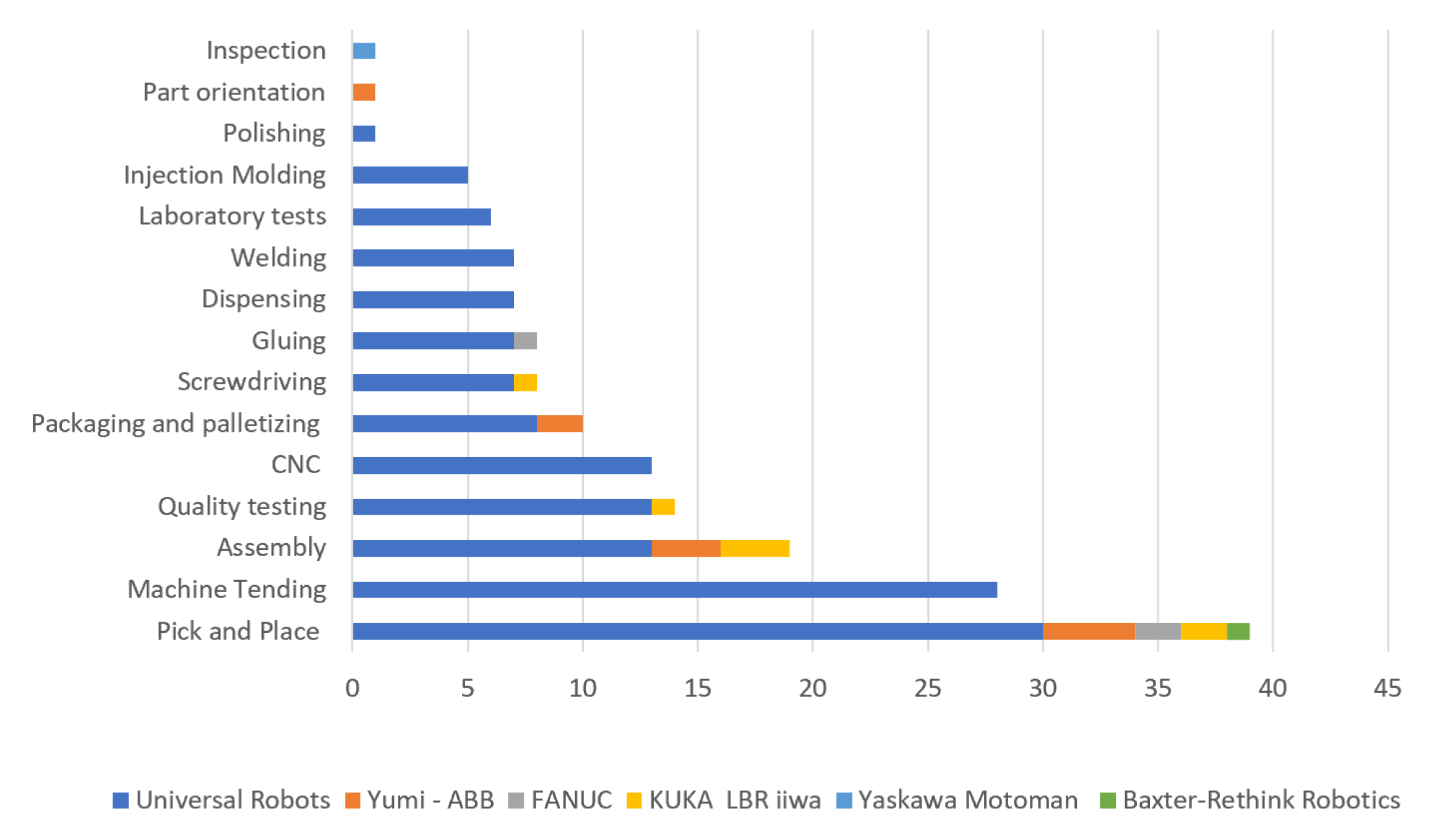
- When grouping the applications of collaborative robots by sector, about three quarters of them belong to electrical engineering and automotive sectors. There are fewer applications in the plant engineering and mechanical fields.
- Focusing on the category of application, the majority of applications concern assembling or material handling.
- Applications where a worker really collaborates in strict contact with the cobot are not very common. In most of the cases, humans and robots coexist sharing the same workspace only occasionally. Furthermore, cobots are usually placed behind a physical fence and used in the same way as classic industrial robots.
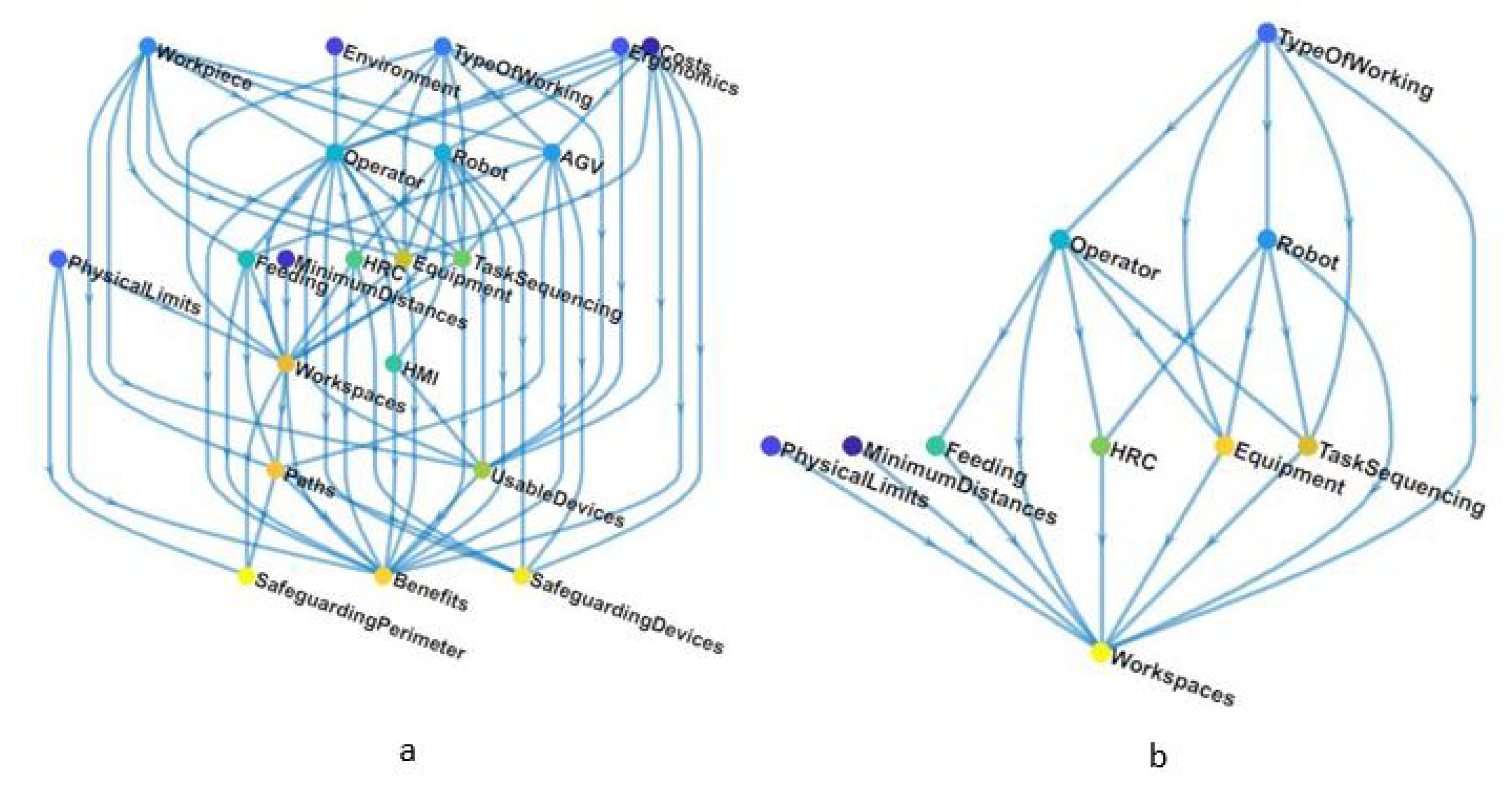
3.2. Knowledge Management
- Logistic domain: refers to all issues related to the division and management of the workspaces, the inclusive and exclusive working areas, the available space, and the management of the material flow strategy within the workplace layout.
- Technological domain: refers to all issues directly correlated with the involved resources, their features, number, and characteristics.
- Safety and ergonomics domain: refers to the human wellness, safety working conditions, and the performance of the control system, including the guards and protective devices.
- Process domain: refers to all issues related to the production, time, task sequencing, interaction, and communication between humans and robots.
- Economic domain: refers to costs and benefits about the collaborative workplace, as well as the performances evaluation.
- Physical limits (PL): available space and any obstacles;
- Workspaces (WS): division into the main workspaces that define the whole workplace layout;
- Paths (P): accesses and exits of the workplace and related paths;
- Feeding (F): means and strategies for material supply;
- Workpiece (WP): main piece to be worked and its components;
- Equipment (EQ): furniture and instruments;
- Usable devices (UD): control devices under operator control;
- Operator (O): operator characteristics;
- Robot (R): robot characteristics;
- Autonomous Guided Vehicle (AGV): AGV characteristics;
- Ergonomics (ER): ergonomic constraints and limitations;
- Environment (EN): environmental working conditions;
- Minimum distances (MD): minimum distance set among both fixed and mobile resources;
- Safeguarding perimeter (SP): physical or virtual workplace limit;
- Safeguarding devices (SD): device not under operator control;
- Type of work (TW): operation to be performed on the workpiece;
- Task sequence (TS): elementary operations scheduled to be performed by humans and robots;
- Human–Robot Collaboration (HRC): interaction between humans and robots;
- Human machine interface (HMI): communication between human and robot;
- Costs (C): economic constraints;
- Benefits (B): key performance indicators (KPI).
3.3. Knowledge Representation
4. The Layout Designing of the Collaborative Workplace Supported by a Modeling Paradigm
4.1. Modeling Paradigm
4.1.1. Elements of Modeling Paradigm
- Process task is a valued-added task; it can be performed by humans and/or robots, using either elementary tools or even machine tools.
- Transport task is a material handling task; it can be performed by human, cobot, mobile manipulators, simple AGVs, as well as by means of passive resources such as conveyors.
- Control task does not contribute materially to the actual processing; it has to be entrusted to human being since it concerns cobot control tasks. It could be performed by means of a human machine interface (HMI) such as pendant controller, smartwatch, tablet, or computer.
- Independent tasks: humans and robots perform different tasks on different workpieces.
- Sequential tasks: humans and robots perform different tasks on the same workpiece placed in the same position. They share the same workspace but at different times (the robot is inactive when a human enters the collaborative space).
- Parallel tasks: humans and robots perform separate tasks for the same goal at the same time. There is no physical contact between the human operator and the robot system. This level includes tasks which are performed inline.
- Collaborative tasks: humans and robots work cooperatively in order to complete the processing of a single workpiece. Contact is allowed (but not strictly necessary) since the robot and human can work “hand-in-hand”.
- 1.
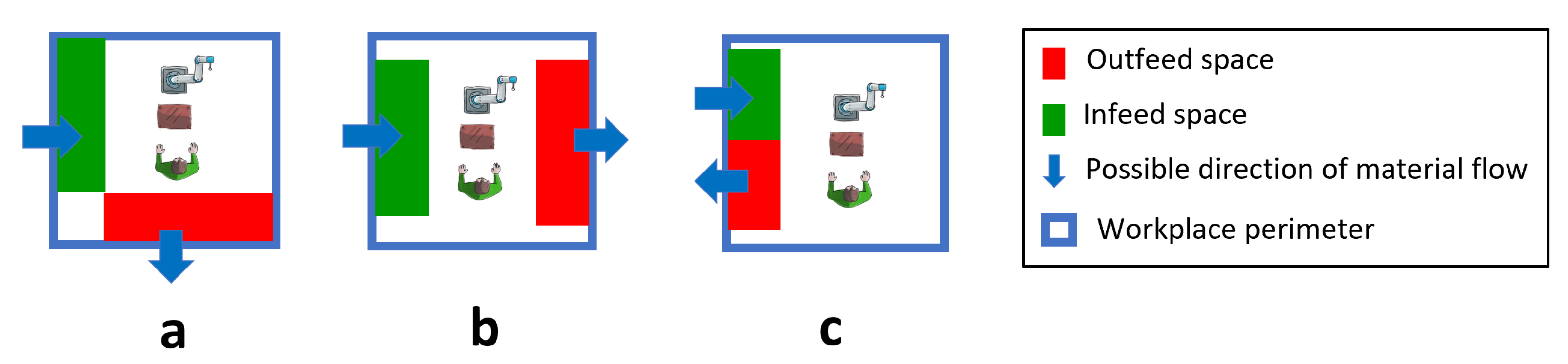
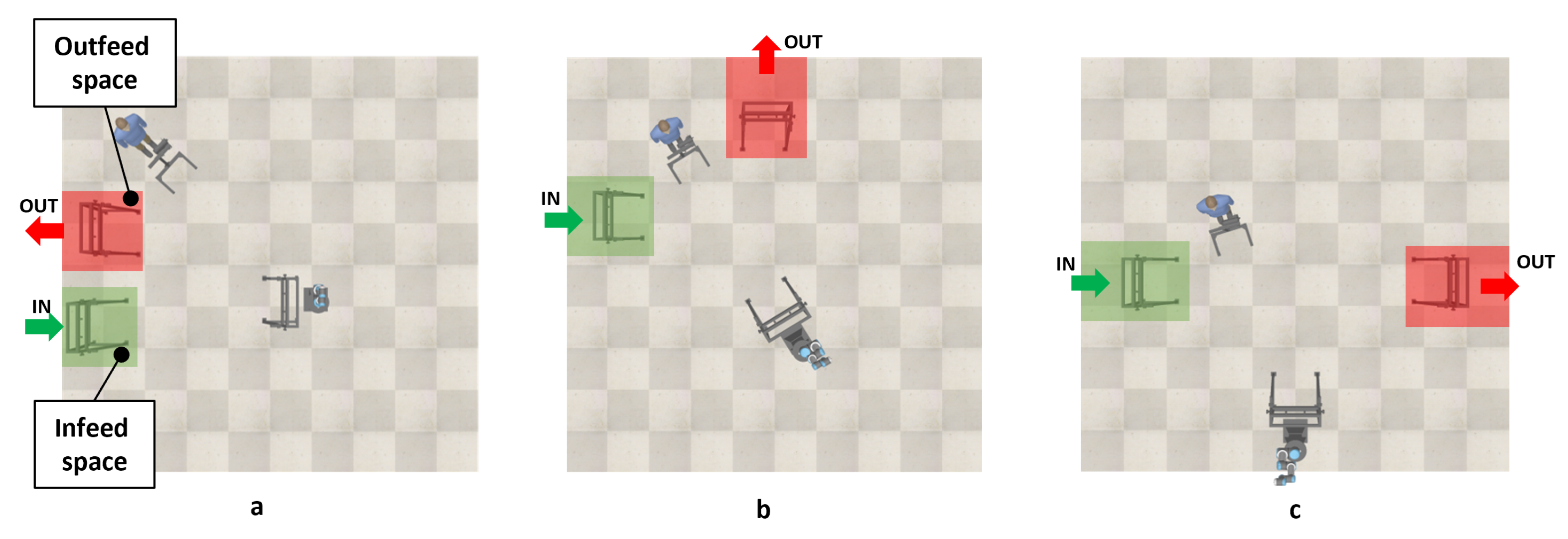
- The infeed spaces receive from the outside the workpiece, supply materials as screws, nuts, bolts, single parts to be assembled, sub-assemblies to be completed, and groups to be processed.
- 2.
- The outfeed spaces receive the processed parts directed outwards. The outfeed spaces dedicated to correctly processed parts should be different from the outfeed spaces dedicated to parts which do not satisfy quality standards and must be reworked or discarded.
- 1.
- Infeed and outfeed spaces are placed near consecutive sides;
- 2.
- Infeed and outfeed spaces are placed near opposite sides;
- 3.
- Infeed and outfeed spaces are placed near the same side.
4.1.2. The Relationship among the Elements of the Paradigm and the Layout Designing
- 1.
- Describes the relevant aspects of the workplaces;
- 2.
- Simplifies the implementation of designing methods;
- 3.
- Identifies changes in the layout of the workplaces.
4.2. Problem formalization
- Set of passive resources P (previously defined in Section 4.1.1) located within the workplace floor with pose defined as ; each passive resource can be characterized by a set of points of interest, e.g., geometrical center of gravity, vertices, and points reachable by active resources;
- Set of active resources A, i.e., robots and human operators as stated in Section 4.1.1, each one characterized by a series of attributes and skills;
- Set of elementary tasks that have to be performed by the active resources or by using passive resources (e.g., machine tools); each task is described by type and level of interaction as stated in Section 4.1.1;
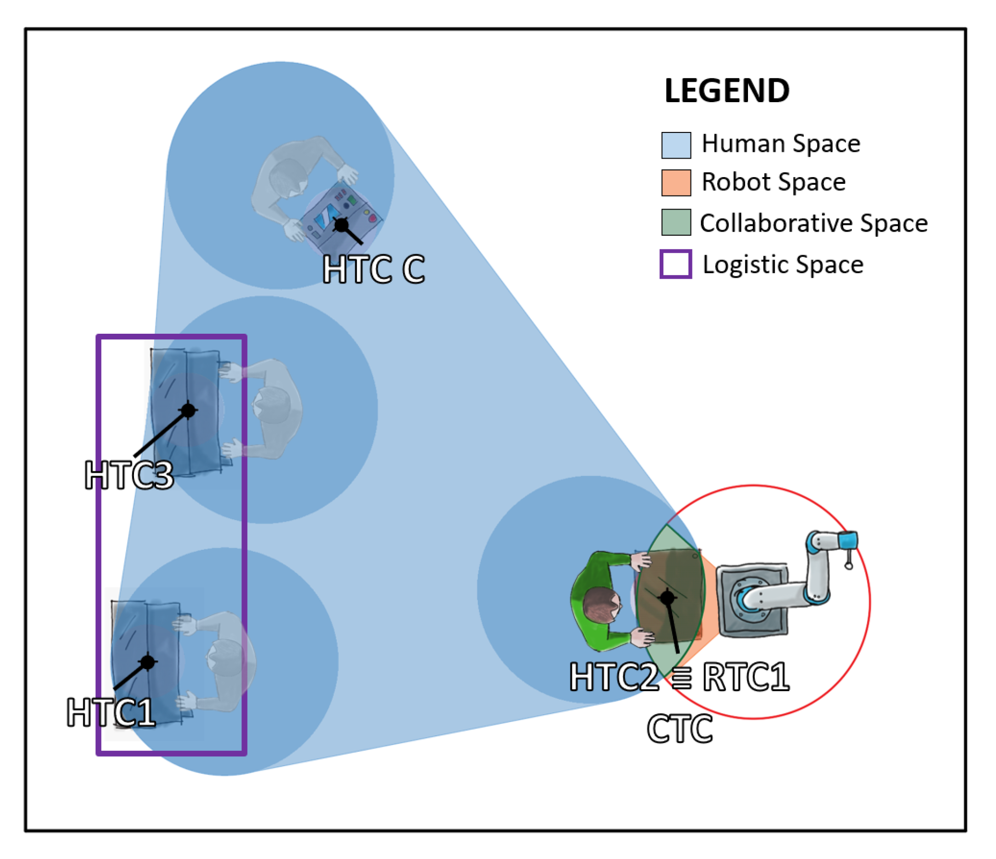
- Set of task centers (i.e., HTC, RTC, and CTC as defined in Section 4.1.1) within the workplace W with pose expressed as ;
- Set of basic locations within the workplace that correspond to the position where workpieces enter/exit the workplace (see the Logistic Spaces definition in Section 4.1.1).
- 1.
- A matrix of task–task center assignments;
- 2.
- A matrix of task center–passive resource assignments;
- 3.
- A matrix of active resource–passive resource assignments.
4.3. Proposed Approach
- The minimum required separation distance between humans and robots established by the ISO/TS15066 [25] with regard to speed and separation monitoring is:The standard clarifies well how each term is determined.
- Safety distances are required to guarantee escape routes [58].
- Maximum load carrying distance should be defined depending on the carried cumulative mass [60].
5. Case Study
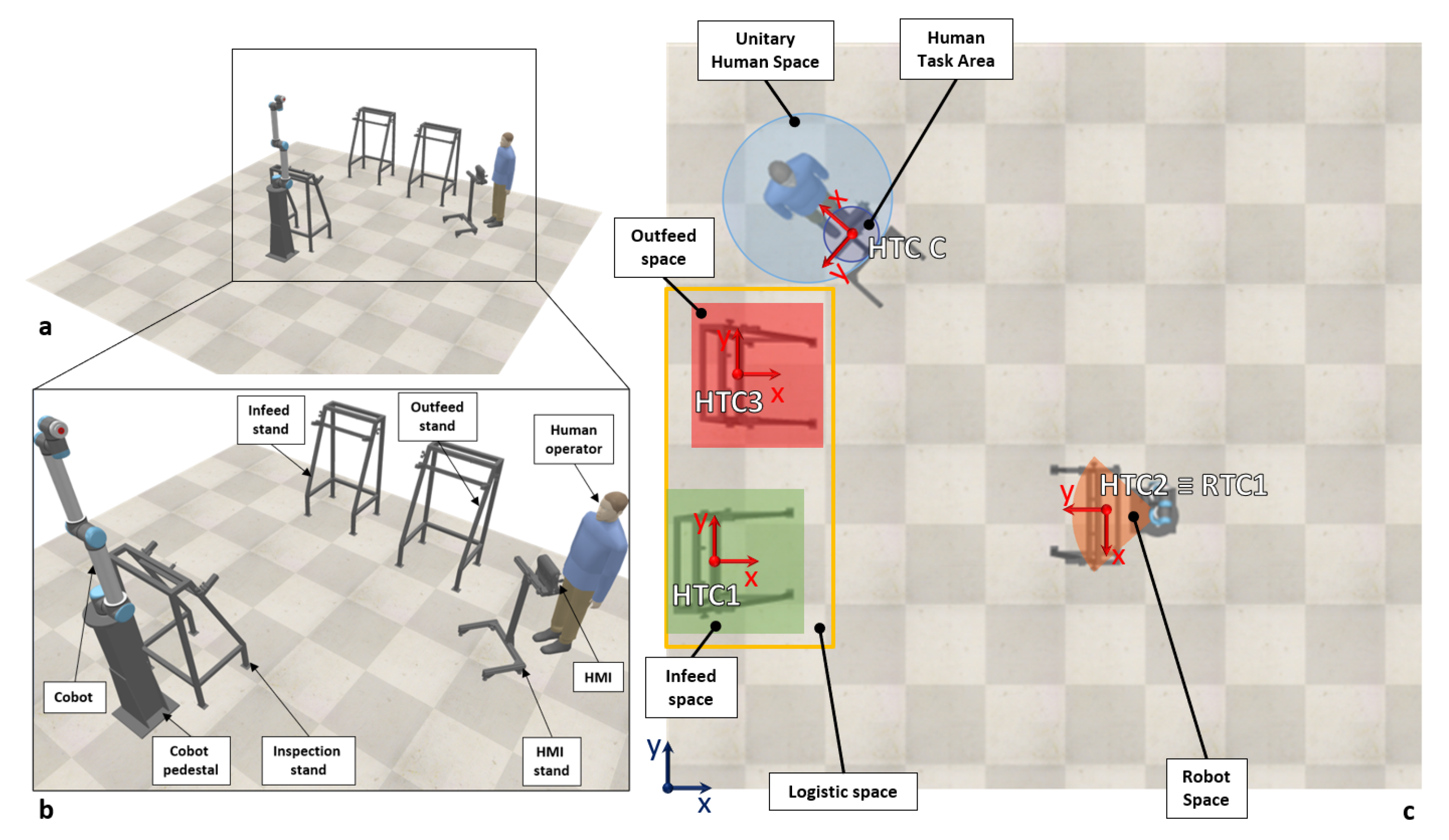
5.1. Collaborative Workplace for Inspection of Welded Parts
- The set of involved passive resources P;
- The set of involved active resources A;
- The set of elementary tasks composing the entire operation and their attributes (i.e., type and level of interaction);
- The set of the task centers distinguished by type (i.e., HTC, RTC, and CTC) according to the procedures described in the previous chapter.
- Infeed stand;
- Outfeed stand;
- Inspection stand;
- Robot pedestal;
- Human Machine Interface.
5.2. What-If Analysis
- Assigning a weight to each function or performance by means of a comparison among them;
- Making the output value of each function dimensionless and on a normalized scale making the best of each function corresponded to the maximum in the normalized scale;
- Multiplying the dimensionless values and the weights;
- Summing the results obtained in the previous step.
- 1.
- Minimum distance: the minimum distance among the resources;
- 2.
- Robot speed: the speed adopted by the robot to carry out the inspection;
- 3.
- Logistic spaces: the relative position of the logistic spaces.
- Impact on space: 38%;
- HRC relevance: 13%;
- Time: 13%;
- Cost: 38%.
6. Results and Discussion
- Minimum distance: 500 mm;
- Robot speed: 0.5 m/s;
- Logistic spaces: the same side.
- 1.
- The minimum distance to consider among the resources should be as less as possible. Indeed a minimum distance of 500 mm is the best according all the evaluation functions and the utility value.
- 2.
- The logistic spaces are located at the same side for all the winning configurations.
- 3.
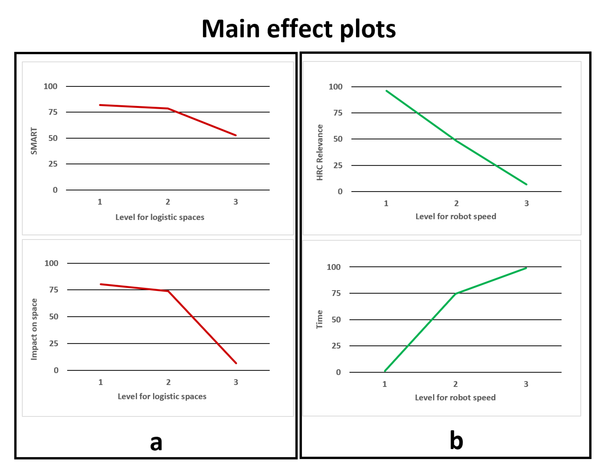
- The robot speed presents a different result. Indeed, the minimum value is considered the best according to the impact on space and the HRC relevance, the middle value is the best solution according to SMART and the maximum value is the best for the time.
- The relative position of the logistic spaces is very significant on the impact on space and the SMART utility value (88.88% and 90.68%);
- The robot speed is very significant on the collaborative time and total time of execution (99.96% and 98.60%);
- The minimum distance has a very low impact on all the performances (less than 9% on all the functions);
- No interaction effect is significant for all the performance (less that 1%).
7. Conclusions
Author Contributions
Funding
Institutional Review Board Statement
Informed Consent Statement
Data Availability Statement
Conflicts of Interest
References
- Nahavandi, S. Industry 5.0—A human-centric solution. Sustainability 2019, 11, 4371. [Google Scholar] [CrossRef]
- Parente, M.; Figueira, G.; Amorim, P.; Marques, A. Production Scheduling in the Context of Industry 4.0: Review and Trends. Int. J. Prod. Res. 2020, 58, 5401–5431. [Google Scholar] [CrossRef]
- Djuric, A.M.; Urbanic, R.; Rickli, J. A Framework for Collaborative Robot (CoBot) Integration in Advanced Manufacturing Systems. SAE Int. J. Mater. Manuf. 2016, 9, 457–464. [Google Scholar] [CrossRef]
- Tan, Q.; Tong, Y.; Wu, S.; Li, D. Anthropocentric Approach for Smart Assembly: Integration and Collaboration. J. Robot. 2019, 2019, 1–8. [Google Scholar] [CrossRef]
- Di Marino, C.; Rega, A.; Vitolo, F.; Patalano, S.; Lanzotti, A. A New Approach to the Anthropocentric Design of Human–Robot Collaborative Environments. Acta IMEKO 2020, 9, 80–87. [Google Scholar] [CrossRef]
- Krüger, J.; Wang, L.; Verl, A.; Bauernhansl, T.; Carpanzano, E.; Makris, S.; Fleischer, J.; Reinhart, G.; Franke, J.; Pellegrinelli, S. Innovative Control of Assembly Systems and Lines. CIRP Ann. 2017, 66, 707–730. [Google Scholar] [CrossRef]
- International Federation of Robotics. World Robotics Industrial Robots; Technical Report; International Federation of Robotics: Frankfurt, Germany, 2019. [Google Scholar]
- Gualtieri, L.; Rauch, E.; Rojas, R.; Vidoni, R.; Matt, D.T. Application of Axiomatic Design for the Design of a Safe Collaborative Human-Robot Assembly Workplace. MATEC Web Conf. 2018, 223, 01003. [Google Scholar] [CrossRef][Green Version]
- Vicentini, F. Collaborative Robotics: A Survey. J. Mech. Des. 2020, 143, 040802. [Google Scholar] [CrossRef]
- Kusiak, A.; Heragu, S.S. The Facility Layout Problem. Eur. J. Oper. Res. 1987, 29, 229–251. [Google Scholar] [CrossRef]
- Drira, A.; Pierreval, H.; Hajri-Gabouj, S. Facility Layout Problems: A Survey. Annu. Rev. Control 2007, 31, 255–267. [Google Scholar] [CrossRef]
- Shiller, Z. Optimal Robot Motion Planning and Work-Cell Layout Design. Robotica 1997, 15, 31–40. [Google Scholar] [CrossRef]
- Scimmi, L.S.; Melchiorre, M.; Troise, M.; Mauro, S.; Pastorelli, S. A Practical and Effective Layout for a Safe Human-Robot Collaborative Assembly Task. Appl. Sci. 2021, 11, 1763. [Google Scholar] [CrossRef]
- Murali, P.; Darvish, K.; Mastrogiovanni, F. Deployment and Evaluation of a Flexible Human–Robot Collaboration Model Based on AND/OR Graphs in a Manufacturing Environment. Intell. Serv. Robot. 2020, 13, 439–457. [Google Scholar] [CrossRef]
- Mateus, J.; Claeys, D.; Limère, V.; Cottyn, J.; Aghezzaf, E.H. Base Part Centered Assembly Task Precedence Generation. Int. J. Adv. Manuf. Technol. 2020, 107, 607–616. [Google Scholar] [CrossRef]
- Bänziger, T.; Kunz, A.; Wegener, K. Optimizing Human–Robot Task Allocation Using a Simulation Tool Based on Standardized Work Descriptions. J. Intell. Manuf. 2020, 31, 1635–1648. [Google Scholar] [CrossRef]
- Kim, W.; Peternel, L.; Lorenzini, M.; Babič, J.; Ajoudani, A. A Human-Robot Collaboration Framework for Improving Ergonomics During Dexterous Operation of Power Tools. Robot. Comput.-Integr. Manuf. 2021, 68, 102084. [Google Scholar] [CrossRef]
- Abobakr, A.; Nahavandi, D.; Hossny, M.; Iskander, J.; Attia, M.; Nahavandi, S.; Smets, M. RGB-D Ergonomic Assessment System of Adopted Working Postures. Appl. Ergon. 2019, 80, 75–88. [Google Scholar] [CrossRef]
- Paletta, L.; Pszeida, M.; Nauschnegg, B.; Haspl, T.; Marton, R. Stress Measurement in Multi-Tasking Decision Processes Using Executive Functions Analysis. Adv. Intell. Syst. Comput. 2020, 953, 344–356. [Google Scholar] [CrossRef]
- Colim, A.; Faria, C.; Braga, A.C.; Sousa, N.; Rocha, L.; Carneiro, P.; Costa, N.; Arezes, P. Towards an Ergonomic Assessment Framework for Industrial Assembly Workstations—A Case Study. Appl. Sci. 2020, 10, 3048. [Google Scholar] [CrossRef]
- Rojas, R.; Wehrle, E.; Vidoni, R. A Multicriteria Motion Planning Approach for Combining Smoothness and Speed in Collaborative Assembly Systems. Appl. Sci. 2020, 10, 5086. [Google Scholar] [CrossRef]
- Matsas, E.; Vosniakos, G.C. Design of a Virtual Reality Training System for Human–Robot Collaboration in Manufacturing Tasks. Int. J. Interact. Des. Manuf. 2017, 11, 139–153. [Google Scholar] [CrossRef]
- ISO 10218-1:2011. Robots and Robotic Devices-Safety Requirements for Industrial Robots-Part 1: Robots; International Organization for Standardization: Geneva, Switzerland, 2011. [Google Scholar]
- ISO 10218-2:2011. Robots and Robotic Devices-Safety Requirements for Industrial Robots-Part 2: Robot Systems and Integration; International Organization for Standardization: Geneva, Switzerland, 2011. [Google Scholar]
- ISO\TS 15066:2016. Robots and Robotic Devices: Collaborative Robots; International Organization for Standardization: Geneva, Switzerland, 2011. [Google Scholar]
- Bdiwi, M.; Pfeifer, M.; Sterzing, A. A New Strategy for Ensuring Human Safety during Various Levels of Interaction with Industrial Robots. CIRP Ann. 2017, 66, 453–456. [Google Scholar] [CrossRef]
- Aaltonen, I.; Salmi, T.; Marstio, I. Refining Levels of Collaboration to Support the Design and Evaluation of Human-Robot Interaction in the Manufacturing Industry. Procedia CIRP 2018, 72, 93–98. [Google Scholar] [CrossRef]
- El Zaatari, S.; Marei, M.; Li, W.; Usman, Z. Cobot Programming for Collaborative Industrial Tasks: An Overview. Robot. Auton. Syst. 2019, 116, 162–180. [Google Scholar] [CrossRef]
- Matheson, E.; Minto, R.; Zampieri, E.G.G.; Faccio, M.; Rosati, G. Human–Robot Collaboration in Manufacturing Applications: A Review. Robotics 2019, 8, 100. [Google Scholar] [CrossRef]
- Malik, A.A.; Bilberg, A. Developing a Reference Model for Human–Robot Interaction. Int. J. Interact. Des. Manuf. 2019, 13, 1541–1547. [Google Scholar] [CrossRef]
- Malik, A.; Brem, A. Digital Twins for Collaborative Robots: A Case Study in Human-Robot Interaction. Robot. Comput. Integr. Manuf. 2021, 68, 102092. [Google Scholar] [CrossRef]
- Kousi, N.; Gkournelos, C.; Aivaliotis, S.; Lotsaris, K.; Bavelos, A.C.; Baris, P.; Michalos, G.; Makris, S. Digital Twin for Designing and Reconfiguring Human–Robot Collaborative Assembly Lines. Appl. Sci. 2021, 11, 4620. [Google Scholar] [CrossRef]
- Boschetti, G.; Bottin, M.; Faccio, M.; Minto, R. Multi-Robot Multi-Operator Collaborative Assembly Systems: A Performance Evaluation Model. J. Intell. Manuf. 2021, 32, 1455–1470. [Google Scholar] [CrossRef]
- Faccio, M.; Minto, R.; Rosati, G.; Bottin, M. The Influence of the Product Characteristics on Human-Robot Collaboration: A Model for the Performance of Collaborative Robotic Assembly. Int. J. Adv. Manuf. Technol. 2020, 106, 2317–2331. [Google Scholar] [CrossRef]
- Tsarouchi, P.; Michalos, G.; Makris, S.; Athanasatos, T.; Dimoulas, K.; Chryssolouris, G. On a Human–Robot Workplace Design and Task Allocation System. Int. J. Comput. Integr. Manuf. 2017, 30, 1272–1279. [Google Scholar] [CrossRef]
- Ore, F.; Sánchez, J.L.J.; Wiktorsson, M.; Hanson, L. Design Method of Human–Industrial Robot Collaborative Workstation with Industrial Application. Int. J. Comput. Integr. Manuf. 2020, 33, 911–924. [Google Scholar] [CrossRef]
- Lietaert, P.; Billen, N.; Burggraeve, S. Model-Based Multi-Attribute Collaborative Production Cell Layout Optimization. In Proceedings of the 2019 20th International Conference on Research and Education in Mechatronics (REM), Wels, Austria, 23–24 May 2019; pp. 1–7. [Google Scholar] [CrossRef]
- Mateus, J.C.; Claeys, D.; Limère, V.; Cottyn, J.; Aghezzaf, E.H. A Structured Methodology for the Design of a Human-Robot Collaborative Assembly Workplace. Int. J. Adv. Manuf. Technol. 2019, 102, 2663–2681. [Google Scholar] [CrossRef]
- Saenz, J.; Behrens, R.; Schulenburg, E.; Petersen, H.; Gibaru, O.; Neto, P.; Elkmann, N. Methods for Considering Safety in Design of Robotics Applications Featuring Human-Robot Collaboration. Int. J. Adv. Manuf. Technol. 2020, 107, 2313–2331. [Google Scholar] [CrossRef]
- Gervasi, R.; Mastrogiacomo, L.; Franceschini, F. A Conceptual Framework to Evaluate Human-Robot Collaboration. Int. J. Adv. Manuf. Technol. 2020, 108, 841–865. [Google Scholar] [CrossRef]
- Ralyté, J.; Jeusfeld, M.; Backlund, P.; Kühn, H.; Arni-Bloch, N. A Knowledge-Based Approach to Manage Information Systems Interoperability. Inf. Syst. 2008, 33, 754–784. [Google Scholar] [CrossRef]
- Favi, C.; Garziera, R.; Campi, F. A Rule-Based System to Promote Design for Manufacturing and Assembly in the Development of Welded Structure: Method and Tool Proposition. Appl. Sci. 2021, 11, 2326. [Google Scholar] [CrossRef]
- Li, Z.; Liang, P.; Avgeriou, P. Application of Knowledge-Based Approaches in Software Architecture: A Systematic Mapping Study. Inf. Softw. Technol. 2013, 55, 777–794. [Google Scholar] [CrossRef]
- Aulinas, M.; Nieves, J.; Cortés, U.; Poch, M. Supporting Decision Making in Urban Wastewater Systems Using a Knowledge-Based Approach. Environ. Model. Softw. 2011, 26, 562–572. [Google Scholar] [CrossRef]
- Ansari, F.; Hold, P.; Khobreh, M. A Knowledge-Based Approach for Representing Jobholder Profile toward Optimal Human–Machine Collaboration in Cyber Physical Production Systems. CIRP J. Manuf. Sci. Technol. 2020, 28, 87–106. [Google Scholar] [CrossRef]
- Michalos, G.; Makris, S.; Tsarouchi, P.; Guasch, T.; Kontovrakis, D.; Chryssolouris, G. Design Considerations for Safe Human-Robot Collaborative Workplaces. Procedia CIRP 2015, 37, 248–253. [Google Scholar] [CrossRef]
- Villani, V.; Pini, F.; Leali, F.; Secchi, C. Survey on Human–Robot Collaboration in Industrial Settings: Safety, Intuitive Interfaces and Applications. Mechatronics 2018, 55, 248–266. [Google Scholar] [CrossRef]
- Matthias, B.; Reisinger, T. Example Application of ISO/TS 15066 to a Collaborative Assembly Scenario. In Proceedings of the ISR 2016: 47st International Symposium on Robotics, Rome, Italy, 21–22 June 2016; pp. 1–5. [Google Scholar]
- Bauer, W.; Bender, M.; Braun, M.; Rally, P.; Scholtz, O. Lightweight Robots in Manual Assembly–Best to Start Simply. Examining Companies’ Initial Experiences with Lightweight Robots; Frauenhofer-Institut für Arbeitswirtschaft und Organisation IAO: Stuttgart, Germany, 2016. [Google Scholar]
- TechNavio. Global Collaborative Robots Market 2020–2024 (Research and Markets). 2020. Available online: https://www.businesswire.com/news/home/20200804005683/en/Analysis-on-Impact-of-COVID-19–Global-Collaborative-Robots-Market-2020-2024-Evolving-Opportunities-with-ABB-Ltd.-and-FANUC-Corp.-Technavio (accessed on 10 December 2021).
- Deo, N. Graph Theory with Applications to Engineering and Computer Science; Dover Publications: Mineola, NY, USA, 2017. [Google Scholar]
- Majeed, A.; Rauf, I. Graph Theory: A Comprehensive Survey about Graph Theory Applications in Computer Science and Social Networks. Inventions 2020, 5, 10. [Google Scholar] [CrossRef]
- Schaeffer, S.E. Graph Clustering. Comput. Sci. Rev. 2007, 1, 27–64. [Google Scholar] [CrossRef]
- Marvel, J.A.; Falco, J.; Marstio, I. Characterizing Task-Based Human–Robot Collaboration Safety in Manufacturing. IEEE Trans. Syst. Man, Cybern. Syst. 2015, 45, 260–275. [Google Scholar] [CrossRef]
- Pheasant, S.; Haslegrave, C.M. Bodyspace: Anthropometry, Ergonomic and the Design of Work, 3rd ed.; CRC Press: Boca Raton, FL, USA, 2018. [Google Scholar]
- Bazaraa, M.; Sherali, H.; Shetty, C. Nonlinear Programming: Theory and Algorithms; Wiley: Hoboken, NJ, USA, 2005; p. 853. [Google Scholar] [CrossRef]
- ISO 13854:2017. Safety of Machinery-Minimum Gaps to Avoid Crushing of Parts of the Human Body; International Organization for Standardization: Geneva, Switzerland, 1993. [Google Scholar]
- ISO 12100:2010. Safety of Machinery-General Principles for Design -Risk Assessment and Risk Reduction; International Organization for Standardization: Geneva, Switzerland, 2010. [Google Scholar]
- ISO 13850:2015. Safety of Machinery-Emergency Stop Function-Principles for Design; International Organization for Standardization: Geneva, Switzerland, 2015. [Google Scholar]
- ISO 11228-1:2003. Ergonomics-Manual Handling-Part 1: Lifting and Carrying; International Organization for Standardization: Geneva, Switzerland, 2003. [Google Scholar]
- ISO 13849-1:2015. Safety of Machinery-Safety-Related Parts of Control Systems-Part 1: General Principles for Design; International Organization for Standardization: Geneva, Switzerland, 2015. [Google Scholar]
- Siregar, D.; Arisandi, D.; Usman, A.; Irwan, D.; Rahim, R. Research of Simple Multi-Attribute Rating Technique for Decision Support. J. Physics Conf. Ser. 2017, 930, 012015. [Google Scholar] [CrossRef]
- Risawandi; Rahim, R. Study of the Simple Multi-Attribute Rating Technique For Decision Support. Int. J. Sci. Res. Sci. Technol. 2016, 2, 491–494. [Google Scholar]
- Barron, F.H.; Barrett, B.E. The Efficacy of SMARTER — Simple Multi-Attribute Rating Technique Extended to Ranking. Acta Psychol. 1996, 93, 23–36. [Google Scholar] [CrossRef]
- Ore, F.; Vemula, B.; Hanson, L.; Wiktorsson, M.; Fagerström, B. Simulation Methodology for Performance and Safety Evaluation of Human–Industrial Robot Collaboration Workstation Design. Int. J. Intell. Robot. Appl. 2019, 3, 269–282. [Google Scholar] [CrossRef]


| Domains | Needs | Groups | Macro Aspects | Elements | Functionalities |
|---|---|---|---|---|---|
| Logistic | Management | Layout | Management of spaces | Physical limits | Spatial constraints |
| Workspaces | Elementary and composed workspaces | ||||
| Movement | Management of flows | Paths | Accessibility | ||
| Feeding | Material flow strategies | ||||
| Technological | Technical | Passive resources | Used to perform tasks | Workpiece | Target to achieve |
| Equipment | Supportive object | ||||
| Usable devices | Support for the operator | ||||
| Active resources | Trained to perform tasks | Operator | Operator features | ||
| Robot | Robot features | ||||
| AGV | AGV features | ||||
| Safety and Ergonomics | Safety and wellness | Human | Human wellness | Ergonomics | Operators constraints |
| Environment | Working conditions | ||||
| Safety | Human safety | Minimum distances | Distance among the resources | ||
| Safeguarding perimeter | Workplace border | ||||
| Safeguarding devices | Safety devices | ||||
| Process | Working | Operations | The aim of the workplace | Type of work | Operation |
| Task sequence | Task sequence and allocation | ||||
| Interaction | Human–robot interaction | HRC | Level of interaction | ||
| HMI | Human–machines communication | ||||
| Economic | Economic | Value | Benefits vs. costs | Costs | Economic constraints |
| Benefits | Key Performance Indicators (KPI) |
| WP | TW | PL | ER | EN | MD | C | O | R | AGV | EQ | UD | TS | HRC | HMI | F | WS | P | SP | SD | B | |
|---|---|---|---|---|---|---|---|---|---|---|---|---|---|---|---|---|---|---|---|---|---|
| WP | 0 | 0 | 0 | 0 | 0 | 0 | 0 | 1 | 1 | 1 | 1 | 1 | 1 | 0 | 0 | 1 | 0 | 1 | 0 | 0 | 0 |
| TW | 0 | 0 | 0 | 0 | 0 | 0 | 0 | 1 | 1 | 1 | 1 | 1 | 1 | 0 | 0 | 0 | 1 | 0 | 0 | 0 | 0 |
| PL | 0 | 0 | 0 | 0 | 0 | 0 | 0 | 0 | 0 | 0 | 0 | 0 | 0 | 0 | 0 | 0 | 1 | 0 | 1 | 0 | 1 |
| ER | 0 | 0 | 0 | 0 | 0 | 0 | 0 | 1 | 0 | 0 | 0 | 1 | 0 | 0 | 0 | 0 | 0 | 0 | 0 | 0 | 0 |
| EN | 0 | 0 | 0 | 0 | 0 | 0 | 0 | 1 | 0 | 0 | 0 | 0 | 0 | 0 | 0 | 0 | 0 | 0 | 0 | 0 | 0 |
| MD | 0 | 0 | 0 | 0 | 0 | 0 | 0 | 0 | 0 | 0 | 0 | 0 | 0 | 0 | 0 | 0 | 1 | 0 | 0 | 0 | 0 |
| C | 0 | 0 | 0 | 0 | 0 | 0 | 0 | 1 | 1 | 1 | 1 | 1 | 0 | 0 | 0 | 0 | 0 | 0 | 0 | 1 | 1 |
| O | 0 | 0 | 0 | 0 | 0 | 0 | 0 | 0 | 0 | 0 | 1 | 1 | 1 | 1 | 1 | 1 | 1 | 0 | 0 | 1 | 1 |
| R | 0 | 0 | 0 | 0 | 0 | 0 | 0 | 0 | 0 | 0 | 1 | 1 | 1 | 1 | 1 | 0 | 1 | 0 | 0 | 1 | 1 |
| AGV | 0 | 0 | 0 | 0 | 0 | 0 | 0 | 0 | 0 | 0 | 0 | 0 | 1 | 0 | 0 | 1 | 0 | 1 | 0 | 1 | 1 |
| EQ | 0 | 0 | 0 | 0 | 0 | 0 | 0 | 0 | 0 | 0 | 0 | 0 | 0 | 0 | 0 | 0 | 1 | 0 | 0 | 0 | 1 |
| UD | 0 | 0 | 0 | 0 | 0 | 0 | 0 | 0 | 0 | 0 | 0 | 0 | 0 | 0 | 0 | 0 | 0 | 0 | 0 | 0 | 1 |
| TS | 0 | 0 | 0 | 0 | 0 | 0 | 0 | 0 | 0 | 0 | 0 | 0 | 0 | 0 | 0 | 0 | 1 | 0 | 0 | 0 | 1 |
| HRC | 0 | 0 | 0 | 0 | 0 | 0 | 0 | 0 | 0 | 0 | 0 | 0 | 0 | 0 | 0 | 0 | 1 | 0 | 0 | 1 | 1 |
| HMI | 0 | 0 | 0 | 0 | 0 | 0 | 0 | 0 | 0 | 0 | 0 | 1 | 0 | 0 | 0 | 0 | 0 | 0 | 0 | 0 | 1 |
| F | 0 | 0 | 0 | 0 | 0 | 0 | 0 | 0 | 0 | 0 | 0 | 0 | 0 | 0 | 0 | 0 | 1 | 1 | 0 | 0 | 1 |
| WS | 0 | 0 | 0 | 0 | 0 | 0 | 0 | 0 | 0 | 0 | 0 | 0 | 0 | 0 | 0 | 0 | 0 | 1 | 1 | 0 | 1 |
| P | 0 | 0 | 0 | 0 | 0 | 0 | 0 | 0 | 0 | 0 | 0 | 0 | 0 | 0 | 0 | 0 | 0 | 0 | 1 | 1 | 1 |
| SP | 0 | 0 | 0 | 0 | 0 | 0 | 0 | 0 | 0 | 0 | 0 | 0 | 0 | 0 | 0 | 0 | 0 | 0 | 0 | 0 | 0 |
| SD | 0 | 0 | 0 | 0 | 0 | 0 | 0 | 0 | 0 | 0 | 0 | 0 | 0 | 0 | 0 | 0 | 0 | 0 | 0 | 0 | 0 |
| B | 0 | 0 | 0 | 0 | 0 | 0 | 0 | 0 | 0 | 0 | 0 | 0 | 0 | 0 | 0 | 0 | 0 | 0 | 0 | 0 | 0 |
| Modeling Paradigm Elements | ||
|---|---|---|
| Workplace components | Active resources | Human operator Cobot |
| Passive resources | Fixtures Machine tools | |
| Workpieces | Main part Subcomponents | |
| Task attributes | Task type | Process task |
| Transport task | ||
| Control task | ||
| Level of interaction | Independent | |
| Sequential | ||
| Parallel | ||
| Collaborative | ||
| Category of application | Material handling | e.g., pick and place, machine tending, palletizing |
| Assembly | e.g., nut fastening, screwdriving | |
| Precision machining | e.g., welding, soldering, gluing, milling | |
| Inspection | e.g., quality testing | |
| Workspaces | Elementary workspaces | Human Space |
| Robot Space | ||
| Composed workspaces | Collaborative Space | |
| Operational Space | ||
| Logistic Space | Infeed Space | |
| Outfeed Space | ||
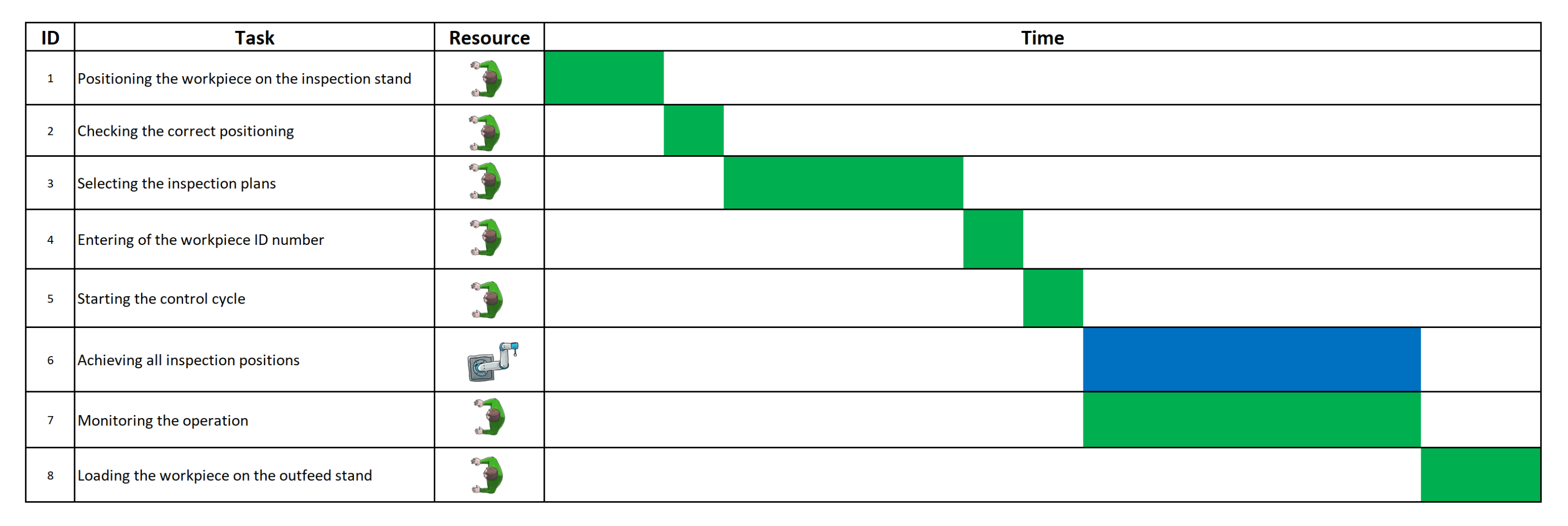
| ID | Task | Task Type | Active Resource | Level of Interaction | Task Center |
|---|---|---|---|---|---|
| 1 | Positioning the workpiece on the inspection stand | Transport | Human Operator | Sequential | HTC 1-HTC 2 |
| 2 | Checking the correct positioning | Process | Human Operator | Sequential | HTC 2 |
| 3 | Selecting the inspection plans | Control | Human Operator | Sequential | HTC C |
| 4 | Entering workpiece ID number | Control | Human Operator | Sequential | HTC C |
| 5 | Starting the control cycle | Control | Human Operator | Sequential | HTC C |
| 6 | Achieving all inspection positions | Process | Cobot UR10 | Collaborative | RTC 1 = HTC2 |
| 7 | Monitoring the operation | Process | Human Operator | Collaborative | HTC 2 |
| 8 | Loading the workpiece on the outfeed stand | Transport | Human Operator | Sequential | HTC 2-HTC 3 |
| ID | Control Factors | Level 1 | Level 2 | Level 2 | Summary |
|---|---|---|---|---|---|
| 1 | Minimum distance | 500 mm | 700 mm | 900 mm | Minimum distances between two generic resources |
| 2 | Robot speed | 0.25 m/s | 0.5 m/s | 0.75 m/s | Speed adopted by the robot to carry out the inspection |
| 3 | Logistic spaces | Same side | Consecutive sides | Opposite sides | Relative position of the infeed and outfeed spaces |
| Name | Function | Objective | Summary |
|---|---|---|---|
| Impact on space | Minimize | Percentage of the total plant available area occupied by the collaborative workplace | |
| HRC relevance | Maximize | Percentage of the total needed execution time characterized by the simultaneous working of human and robot | |
| Time | Minimize | Total needed execution time | |
| Cost | Minimize | Total cost as the sum of all the active and passive resources | |
| SMART | Maximize | Weighted combination of the previous functions |
| Conf. | Minimum Distance | Robot Speed | Logistic Spaces | Impact on Space | HRC Relevance | Time | Cost | SMART |
|---|---|---|---|---|---|---|---|---|
| 1 | 500 | 0.25 | Same side | 16.72 | 91.35 | 175.16 | 3000 | 87.76 |
| 2 | 500 | 0.25 | Consecutive side | 17.30 | 90.87 | 176.08 | 3000 | 84.59 |
| 3 | 500 | 0.25 | Opposite side | 23.74 | 90.20 | 177.39 | 3000 | 54.30 |
| 4 | 500 | 0.5 | Same side | 16.90 | 83.97 | 95.28 | 3000 | 90.44 |
| 5 | 500 | 0.5 | Consecutive side | 17.43 | 83.16 | 96.19 | 3000 | 87.26 |
| 6 | 500 | 0.5 | Opposite side | 23.98 | 82.04 | 97.51 | 3000 | 56.08 |
| 7 | 500 | 0.75 | Same side | 17.10 | 77.58 | 68.75 | 3000 | 87.63 |
| 8 | 500 | 0.75 | Consecutive side | 17.64 | 76.56 | 69.66 | 3000 | 84.22 |
| 9 | 500 | 0.75 | Opposite side | 24.26 | 75.14 | 70.98 | 3000 | 52.54 |
| 10 | 700 | 0.25 | Same side | 18.12 | 91.27 | 175.31 | 3000 | 81.21 |
| 11 | 700 | 0.25 | Consecutive side | 18.62 | 90.72 | 176.36 | 3000 | 78.39 |
| 12 | 700 | 0.25 | Opposite side | 24.10 | 90.20 | 177.39 | 3000 | 52.65 |
| 13 | 700 | 0.5 | Same side | 18.34 | 83.83 | 95.43 | 3000 | 83.68 |
| 14 | 700 | 0.5 | Consecutive side | 18.78 | 82.92 | 96.48 | 3000 | 80.83 |
| 15 | 700 | 0.5 | Opposite side | 24.33 | 82.04 | 97.51 | 3000 | 54.48 |
| 16 | 700 | 0.75 | Same side | 18.54 | 77.41 | 68.90 | 3000 | 80.83 |
| 17 | 700 | 0.75 | Consecutive side | 19.02 | 76.25 | 69.95 | 3000 | 77.60 |
| 18 | 700 | 0.75 | Opposite side | 24.59 | 75.14 | 70.98 | 3000 | 50.98 |
| 19 | 900 | 0.25 | Same side | 19.45 | 91.19 | 175.47 | 3000 | 75.04 |
| 20 | 900 | 0.25 | Consecutive side | 20.08 | 90.58 | 176.63 | 3000 | 71.50 |
| 21 | 900 | 0.25 | Opposite side | 24.38 | 90.20 | 177.39 | 3000 | 51.33 |
| 22 | 900 | 0.5 | Same side | 19.70 | 83.70 | 95.58 | 3000 | 77.28 |
| 23 | 900 | 0.5 | Consecutive side | 20.29 | 82.69 | 96.75 | 3000 | 73.65 |
| 24 | 900 | 0.5 | Opposite side | 24.61 | 82.04 | 97.51 | 3000 | 53.20 |
| 25 | 900 | 0.75 | Same side | 19.92 | 77.23 | 69.05 | 3000 | 74.32 |
| 26 | 900 | 0.75 | Consecutive side | 20.52 | 75.95 | 70.22 | 3000 | 70.44 |
| 27 | 900 | 0.75 | Opposite side | 24.86 | 75.14 | 70.98 | 3000 | 49.74 |
| ANOVA Analysis | |||
|---|---|---|---|
| SMART | Impact on space | ||
| Minimum distance | 8.14% | Minimum distance | 8.93% |
| Robot speed | 2.98% | Robot speed | 0.40% |
| Logistic spaces | 88.88% | Logistic spaces | 90.68% |
| HRC relevance | Time | ||
| Minimum distance | 0.00% | Minimum distance | 0.03% |
| Robot speed | 99.96% | Robot speed | 98.60% |
| Logistic spaces | 0.04% | Logistic spaces | 1.37% |
Publisher’s Note: MDPI stays neutral with regard to jurisdictional claims in published maps and institutional affiliations. |
© 2021 by the authors. Licensee MDPI, Basel, Switzerland. This article is an open access article distributed under the terms and conditions of the Creative Commons Attribution (CC BY) license (https://creativecommons.org/licenses/by/4.0/).
Share and Cite
Rega, A.; Di Marino, C.; Pasquariello, A.; Vitolo, F.; Patalano, S.; Zanella, A.; Lanzotti, A. Collaborative Workplace Design: A Knowledge-Based Approach to Promote Human–Robot Collaboration and Multi-Objective Layout Optimization. Appl. Sci. 2021, 11, 12147. https://doi.org/10.3390/app112412147
Rega A, Di Marino C, Pasquariello A, Vitolo F, Patalano S, Zanella A, Lanzotti A. Collaborative Workplace Design: A Knowledge-Based Approach to Promote Human–Robot Collaboration and Multi-Objective Layout Optimization. Applied Sciences. 2021; 11(24):12147. https://doi.org/10.3390/app112412147
Chicago/Turabian StyleRega, Andrea, Castrese Di Marino, Agnese Pasquariello, Ferdinando Vitolo, Stanislao Patalano, Alessandro Zanella, and Antonio Lanzotti. 2021. "Collaborative Workplace Design: A Knowledge-Based Approach to Promote Human–Robot Collaboration and Multi-Objective Layout Optimization" Applied Sciences 11, no. 24: 12147. https://doi.org/10.3390/app112412147
APA StyleRega, A., Di Marino, C., Pasquariello, A., Vitolo, F., Patalano, S., Zanella, A., & Lanzotti, A. (2021). Collaborative Workplace Design: A Knowledge-Based Approach to Promote Human–Robot Collaboration and Multi-Objective Layout Optimization. Applied Sciences, 11(24), 12147. https://doi.org/10.3390/app112412147